1. Introduction
Autonomous vehicle technology is an emerging technology expected to alleviate traffic congestion and improve people’s well-being [
1]. Among them, SBW is a key technology for achieving autonomous driving and a crucial part of SBW chassis, and has become a research hotspot among scholars and engineers at home and abroad [
2].
With the continuous advancement of autonomous driving, the demand for vehicle stability and trajectory tracking precision has reached unprecedented levels. Sophisticated high-level decision-making and motion planning algorithms, such as hybrid model predictive control for seamless overtaking [
3] and safety-enhanced reinforcement learning frameworks [
4], have significantly improved the oscillation-free capabilities of autonomous vehicles in complex environments [
5,
6].
SBW systems typically use a single steering drive motor as the power source. However, this design has potential risks; if the motor fails, the system may lose steering capability entirely. To improve system reliability and safety, a dual-motor redundant design was introduced. This redundant design significantly enhances the system’s fault tolerance and safety level, providing more reliable execution for autonomous driving functions [
7,
8,
9]. Among these, due to the dynamic coupling between the two motors, they may operate asynchronously, leading to issues with steering mechanism tracking accuracy and mechanical component wear. Developing advanced control algorithms with higher control precision and better synchronization performance for these issues is of great value in enhancing the reliability and safety of autonomous driving systems.
The primary challenge of dual-motor redundant SBW systems lies in the dynamic coupling and potential asynchronous operation between the two motors, which becomes especially critical during sudden actuator failures. To address these issues, researchers have proposed various advanced fault-tolerant and synchronization control strategies, which generally fall into three categories:
Active Disturbance Rejection Control (ADRC): ADRC is highly effective in dealing with internal and external uncertainties. For instance, Shao et al. [
10] applied an extended state observer to estimate load torques, while Shi et al. [
11] combined ADRC with parameter identification to improve the current loop accuracy of permanent magnet synchronous motors. However, during a sudden and severe motor failure (a massive step disturbance), the state observers in ADRC inherently introduce a phase lag, which compromises the immediate transient response.
Sliding Mode Control (SMC): SMC is renowned for its absolute robustness against parameter variations. Ding et al. [
12] designed a sliding mode synchronization controller based on a decoupled structure, and Miao et al. [
13] utilized a fractional-order SMC to enhance dual-motor tracking precision. Despite these improvements, traditional SMC inherently suffers from high-frequency chattering, which severely accelerates the mechanical wear of the steering rack and pinion over time.
Coordinated and Adaptive Control: Other approaches focus on dynamic allocation architectures. Yang et al. [
14] proposed an optimal coordinated control strategy combining a master-slave structure with a linear quadratic regulator (LQR) to improve torque synchronization. While performing well under nominal conditions, these coordinated methods often require complex, discrete logic switching upon detecting a fault, which can cause torque jumps and compromise the continuity of lateral acceleration.
To overcome the phase lag of ADRC, the chattering of SMC, and the complex logic switching of coordinated control, the ZNN has emerged as a powerful continuous solver for time-varying nonlinear problems [
15,
16]. ZNN utilizes time-varying partial derivatives to provide forward predictive compensation, offering a highly promising perspective for real-time dynamic redundancy allocation without chattering [
17].
Compared to the aforementioned conventional strategies, the proposed ZNN based framework exhibits distinct methodological novelty. First, unlike sliding mode control which struggles with inherent high frequency chattering that accelerates mechanical wear, the continuous neural dynamic evolution of ZNN generates inherently smooth control commands. Second, compared to active disturbance rejection control which relies on state observers that may introduce phase lag during sudden severe faults, ZNN utilizes time varying partial derivatives to provide forward predictive compensation, significantly enhancing real time responsiveness. Finally, in contrast to traditional coordinated control that depends on complex discrete logic switching for fault management, the integration of ZNN with a Jacobian pseudoinverse allows for continuous, instantaneous structural torque reallocation. This unified mathematical approach elegantly bypasses the need for complicated logic triggers.
In this paper, a hierarchical fault-tolerant trajectory tracking control strategy is proposed to bridge the gap between microscopic actuator reliability and macroscopic vehicle safety for autonomous SBW systems. The primary objective is to achieve instantaneous control authority reconfiguration at the execution level while maintaining high-fidelity path-following performance at the vehicle level. To this end, a coordinated architecture consisting of an upper-layer Stanley planner and a lower-layer ZNN-based controller is established. The main conclusions and findings of this research are summarized as follows:
(1) The proposed ZNN controller, integrated with a Jacobian pseudo-inverse mechanism, enables millisecond-level torque reallocation during motor failures, effectively eliminating the dynamic phase lag inherent in traditional feedback controllers.
(2) By incorporating prescribed performance functions, the physical rack tracking error is mathematically guaranteed to remain within predefined safety boundaries, even under severe fault shocks.
(3) Comparative simulation results demonstrate that the proposed method reduces the lateral tracking RMSE by more than 85% compared to conventional PID control, significantly enhancing the fault-operational capability and improved system stability of autonomous driving systems.
2. Materials and Methods: System Modeling
The development of a robust fault-tolerant trajectory tracking architecture for autonomous vehicles with redundant SBW systems necessitates a precise mathematical representation of the physical plant. To capture the fundamental dynamics while maintaining computational efficiency for real-time control, a hierarchical modeling approach is adopted in this study. This section details the theoretical framework and the plant models that serve as the basis for the subsequent controller design. Specifically, a two-degree-of-freedom (2-DOF) vehicle model is first established to characterize the macroscopic lateral and yaw motions. Subsequently, a dynamic model of the redundant SBW actuator, featuring a dual-motor configuration, is developed to facilitate the investigation of actuator faults and the corresponding torque-reallocation mechanisms.
2.1. 2-DOF Vehicle Dynamics Model
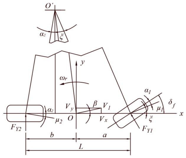
Taking the car’s center of mass as the origin of the vehicle coordinate system,
Ox and
Oy are the vertical and horizontal axes of the vehicle coordinate system, respectively. The component of the center of mass velocity
V1 at time t on the
Ox axis is
Vx, and the component on the
Oy axis is
Vy, as shown in
Figure 1.
To decouple the lateral dynamics from spatial multi-axis motions, this study assumes a constant longitudinal velocity and neglects the heave, roll, and pitch degrees of freedom. By equivalently combining the left and right wheels, the tire-road lateral forces
FY1 and
FY2 under the small-angle linear assumption are formulated as:
where
k1 and
k2 represent the cornering stiffness of the front and rear tires, respectively;
α1 and
α2 denote the corresponding tire slip angles, which are defined as follows:
Combining the mechanical equilibrium relationship and the kinematic relationship, the following vehicle dynamics equations are obtained:
where
β is the center of gravity (CG) sideslip angle,
is the front-wheel steering angle,
ωr is the yaw rate,
m is the vehicle mass,
IZ is the yaw moment of inertia about the
Z-axis, and
a and
b represent the distances from the CG to the front and rear axles, respectively.
2.2. Tire Force and Self-Aligning Torque Feedback
Based on the linear tire model assumption, under the condition of small tire slip angles, the lateral forces
and
generated by the ground on the front and rear wheels are proportional to their respective slip angles, which can be expressed as:
When tire slip occurs, the interaction between the lateral tire force and the total trail (comprising mechanical and pneumatic trails) generates a self-aligning torque that forces the steered wheels to return to the straight-ahead position. In chassis SBW systems, this torque constitutes the primary nonlinear time-varying external disturbance. The self-aligning torque
acting around the kingpin
Z-axis can be expressed as:
2.3. Equivalent Dynamic Model of Dual-Motor SBW System
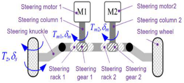
The dual-motor SBW system mainly consists of two steering drive motors, a reducer, a gear rack and pinion, and steering wheels. The overall structure is shown in
Figure 2.
The dual-motor SBW system is driven by two motors, and its rotor dynamics equation is:
In the formula, , are the rotational inertia of the rotors of steering motors 1 and 2, , are the damping coefficients of the rotors of steering motors 1 and 2, respectively, , are the steering angles of steering motors 1 and 2, respectively, , are the electromagnetic torques of steering motors 1 and 2, , are the load torques of steering motors 1 and 2, and , are the eddy current electromagnetic torques of steering motor 1, taking into account the eddy current electromagnetic torques of the motor.
In actual steering, the front wheel steering knuckle is rigidly connected to the rack and pinion mechanism via a tie rod. Under the assumption of small-angle steering, the kinematic relationship between the linear displacement
of the rack and the front wheel steering angle
is:
In the formula, is the equivalent length of the steering knuckle arm.
To avoid state redundancy and repetitive inertial calculations caused by independently establishing the dynamic equations for the front wheel and rack, the rotational inertia
and viscous damping
of the front wheel are equivalently converted to the translational direction of the rack, yielding the system’s equivalent mass
and equivalent damping
:
The restoring torque
and frictional resistance torque
acting on the wheel are converted into the equivalent load resistance
acting on the rack:
Combining the above equivalent parameters, and considering the transmitted torque generated by the torsional stiffness
of the motor shaft:
Finally, the global equivalent dynamic equation of the gear and rack under complex load, driven by two motors, is obtained as follows:
3. Controller Design: Hierarchical Fault-Tolerant Architecture
The dual-motor SBW system not only suffers from strong mechanical coupling between the two motors, but is also subject to highly nonlinear interference from the equivalent restoring torque , which varies in real time with vehicle speed and steering angle. Traditional linear control methods struggle to maintain high-precision trajectory tracking performance when faced with sudden single-motor failures and such time-varying disturbances. Therefore, to achieve high-precision trajectory tracking for the entire vehicle and ensure the fault tolerance of the underlying actuators, a hierarchical control architecture is proposed.
3.1. Upper-Level Trajectory Planner Based on Stanley Algorithm
To generate a dynamic, time-varying steering reference input that conforms to real physical laws, the controller employs the classic Stanley algorithm. The Stanley algorithm uses nonlinear feedback control by combining the vehicle’s heading error and cross-track error.
Let the vertical distance from the vehicle’s front axle center to the reference trajectory be the cross-track error
, and the angle between the vehicle’s current heading and the trajectory tangent be the heading error
The desired front wheel steering angle
output by the upper-level controller:
In the formula, represents the longitudinal velocity of the vehicle, and is the gain parameter used to adjust the fixation sensitivity to the lateral pallet.
To interface with the ZNN dual-motor fault-tolerant controller, the “desired rack relationship” needs to be converted to the “desired rack relationship”. the desired rack
is calculated as follows:
3.2. Design of a ZNN-Based Dual-Motor Fault-Tolerant Controller
The underlying objective of the dual-motor SBW system is rack displacement. The scalar tracking error
between the actual and desired system displacement is defined as:
To improve tracking performance and limit error overshoot and steady-state limits, time-converging performance constraints
and
are applied to the system error:
where
represents the boundary convergence rate, and
.
represent the initial error range and the allowable steady-state error limit, respectively.
An intermediate variable
is introduced to perform a nonlinear transformation on the bounded error, mapping it to the interval (0, 1):
Furthermore, the above variables are mapped to unbounded state variables
using a logarithmic function:
To drive the aforementioned unbounded error state to converge to zero, the ZNN evolution equation of the following form is established:
In the formula, is the design constant for scaling the convergence speed of the ZNN.
According to the chain rule, the total derivative of
can be expanded into partial derivatives with respect to error
and time
:
To simplify the expression, let
. Combining with the definition of tracking error
, substituting into the ZNN evolution equation:
The linear velocity
of the rack is jointly determined by the angular velocities
of the two motors. Here, the Jacobian matrix
of the transmission system is introduced to establish the kinematic mapping relationship.
Substituting this mapping into the above equation yields an implicit equation containing the control variable
:
Since the Jacobian matrix
is a non-square matrix, the system is a redundant drive system. To find the optimal command allocation that minimizes the energy consumption of the two motors, the pseudo-inverse
of the Jacobian matrix is introduced, ultimately calculating the desired dual-motor speed control command:
In this ZNN redundancy allocation framework based on the Jacobian pseudo-inverse, if the system detects a partial or complete torque failure in a motor (e.g., motor 1), it only needs to decay or set the corresponding column element in the Jacobian matrix J to zero (e.g., ) in the algorithm. Physically, reducing the corresponding column in the Jacobian matrix to zero represents a fail silent state where the motor completely loses its torque generating capability. In real world automotive applications, this scenario corresponds to severe hardware or electrical failures, such as an inverter power stage breakdown, severed phase cables, or an emergency power cut off initiated by the electronic control unit upon detecting critical internal errors. Mathematically modeling this as a zeroed Jacobian column allows the algorithm to simulate the instantaneous decoupling of the faulty actuator, forcing the pseudoinverse mechanism to seamlessly transfer the steering load to the remaining healthy motor. At this time, the real-time recalculation of will automatically and smoothly transfer the steering load originally belonging to motor 1 to the healthy motor 2, thereby achieving rapid fault-tolerant reconstruction at the lower level and ensuring the safety and continuity of trajectory tracking at the upper level.
Remark 1. While standard ZNN are theoretically sensitive to dynamic noise, this system compensates for practical perturbations through two mechanisms. First, from an engineering perspective, raw sensor signals are assumed to be pre-processed by low-pass filters to eliminate high-frequency harmonics. Second, the high convergence parameter provides inherent algorithmic suppression. Under bounded noise, the maximum residual error is tightly constrained and inversely proportional to this large design parameter, effectively attenuating the impact of digital rounding errors without introducing the phase lag associated with integral-type modifications.
Remark 2. Regarding the practical implement ability of the proposed design, it is important to note that the low dimensional nature of the system yields a direct analytical inverse solution. This requires minimal computational overhead, executing at the microsecond level on standard automotive microcontrollers without iterative solvers. Furthermore, the hierarchical decoupling of upper level planning and lower level execution aligns seamlessly with the modular software architecture in modern intelligent vehicle engineering, ensuring its practical acceptability, ease of integration, and straightforward calibration.
Remark 3 (Numerical Stability, Singularity, and Actuator Saturation). It is crucial to address the specific boundary conditions of the pseudo-inverse reallocation strategy. Unlike typical multi degree of freedom robotic manipulators that suffer from state dependent kinematic singularities, the Jacobian matrix of the dual motor rack and pinion system is governed by fixed mechanical gear ratios. Consequently, the pseudo-inverse calculation fundamentally requires only the inversion of a strictly positive scalar. This guarantees absolute numerical stability during both severe single motor failures and partial actuator degradation scenarios, avoiding matrix ill conditioning. A true singularity only emerges during a simultaneous total failure of both motors, which implies an uncontrollable physical system.
Furthermore, from a hardware perspective, mathematical torque reallocation cannot overcome absolute physical limits. In the event of a complete single motor failure, the remaining motor is instantaneously commanded to overcome the total nonlinear self-aligning torque. Should this exceed its maximum torque capacity, actuator saturation will occur, temporarily compromising the tracking accuracy defined by the prescribed performance bounds. Thus, the successful deployment of this fault tolerant framework inherently relies on the fail operational hardware design principle, where each redundant motor is sized with sufficient margin to independently manage peak emergency dynamic loads.
3.3. Stability Analysis and Convergence Proof
For a dual-motor SBW system with multiple uncertainties and faults, under the action of controller , the mapping error asymptotically converges to zero globally, and the system’s original tracking error can be strictly maintained within the preset performance boundary and asymptotically converge to zero.
The following Lyapunov function
is constructed:
Clearly, holds if and only if , and holds for any .
Take the time derivative with respect to
and substitute it into the closed-loop control evolution process of the system:
Substituting the actual physical execution state
into
, and combining it with the pseudo-inverse property
(for a full-rank row matrix), we can obtain:
Therefore, the derivative of the Lyapunov function is:
Since
,
is a negative definite function. According to Lyapunov’s stability theorem, this guarantees that
for all
, which implies that the mapped state
is strictly bounded. Specifically, the supremum of its absolute value is constrained by its initial state:
Based on the strictly monotonically increasing nature of the inverse diffeomorphic mapping, the intermediate variable
can be explicitly expressed as:
Because
is bounded as proven above,
is strictly bounded away from the singular points 0 and 1. We can establish the rigorous analytical bounds for
as follows:
This topological property mathematically guarantees that for any time
, the intermediate variable
strictly resides within the open interval (0, 1). By substituting this back into the original error definition, it provides a rigorous theoretical guarantee that the physical lateral tracking error
never violates the predefined transient performance constraints:
Furthermore, the negative definiteness of
indicates that
. By applying this asymptotic convergence to the continuous inverse mapping, the steady-state limit of
is strictly determined:
Recalling the symmetric boundary condition where
, the original tracking error
can be reconstructed as:
Taking the limit as time approaches infinity, we obtain the final steady-state tracking error:
This completes the rigorous mathematical proof that the proposed controller not only guarantees the global asymptotic convergence of the tracking error to zero but also ensures strict adherence to the dynamic safety boundaries throughout the entire driving maneuver.
Remark 4 (Sensitivity and Practical Implementation Robustness). Regarding the practical engineering implementation of the proposed ZNN controller, its reliance on derivative related evolution dynamics introduces inherent sensitivity to measurement noise, parameter uncertainty, and actuator delay. In a real world automotive deployment, raw sensor signals must be preprocessed using standard low pass filters or Kalman filtering to prevent high frequency noise amplification within the derivative calculations. Furthermore, while the system faces parameter uncertainties such as varying tire stiffness, the ZNN algorithm handles these as bounded lumped disturbances. The high convergence gain of the network provides robust suppression of these variations. Lastly, the analytical nature of the Jacobian pseudoinverse minimizes computational delay to the microsecond level, ensuring that the primary control loop remains stable against typical automotive communication and mechanical delays.
4. Simulation Results and Discussion
To fully verify the effectiveness of the proposed hierarchical collaborative control architecture of “upper-level trajectory planning and lower-level ZNN fault-tolerant execution,” a closed-loop simulation system for a dual-motor redundant SBW vehicle was built in the MATLAB/Simulink R2024a environment. To fully highlight the superiority of the ZNN control strategy, a classic Proportional-Integral-Derivative (PID) controller was selected as the benchmark comparison algorithm. Simulation tests covered two typical operating conditions: continuously alternating sine wave steering and dual lane change steering (DLC) with emergency obstacle avoidance.
4.1. Simulation Setup
The simulation system includes a two-degree-of-freedom vehicle dynamics model, a dual-motor rack and pinion actuator model, and a controller module. The simulation step size is set to 0.001 s. Simulation parameters are shown in
Table 1.
The simulation settings are as follows:
- (1)
The simulation time interval is set to 0.001 s;
- (2)
The uncertainty perturbation of the additive supply is set to ±5% of ;
- (3)
The uncertainty perturbations of the front and rear wheel stiffness are set to ±5% of and , respectively.
- (4)
The selected PID parameters ( = 50, = 5, = 0.1).
- (5)
The selected ZNN parameters ( = 300, = 0.2, = 0.0005, = 1.0)
It is critical to justify the computational feasibility of the proposed ZNN controller for real time automotive microcontrollers. Unlike deep learning networks, the ZNN framework utilized here serves as a dynamic algebraic solver. For the dual motor system, the Jacobian matrix is a 1 by 2 vector. Consequently, calculating the pseudoinverse strictly involves scalar inversion rather than complex matrix factorization. The entire control execution fundamentally requires only a finite sequence of basic floating point operations (additions, multiplications, and a single division), yielding a mathematical computational complexity of exactly O (1). On a standard 32 bit automotive chassis microcontroller operating at standard clock speeds (e.g., 200 MHz), this O (1) calculation is executed in single digit microseconds. This microsecond level execution time fits effortlessly within a deterministic 1 millisecond chassis control task cycle, ensuring that the theoretical “millisecond level fault reconstruction” and elimination of algorithmic phase lag are fully achievable in physical hardware implementation.
While this study utilizes a classical PID framework as the transparent industrial baseline to explicitly demonstrate the instantaneous reconfiguration capability of the Jacobian pseudoinverse, it is crucial to position the proposed ZNN framework relative to other advanced fault tolerant controllers.
Compared to Sliding Mode Control (SMC), which inherently suffers from high frequency control effort chattering, the continuous neural dynamic evolution of ZNN ensures smooth torque reallocation, critically protecting the mechanical lifespan of the steering rack. Compared to Active Disturbance Rejection Control (ADRC), which relies on extended state observers that are prone to estimation phase lag during abrupt motor failures, the ZNN utilizes time varying partial derivatives to provide immediate predictive compensation. Finally, compared to Model Predictive Control (MPC), which demands heavy online optimization and rolling horizon calculations, the proposed ZNN framework yields a direct analytical solution. This drastically reduces the computational burden, allowing execution at the microsecond level, which is a decisive advantage for practical implementation on standard automotive chassis microcontrollers. Future empirical studies will focus on quantitative benchmarking against these advanced algorithms in dynamic Hardware in the Loop testbenches.
To ensure a rigorous and fair comparative analysis, the parameters of the baseline PID controller were strictly calibrated rather than arbitrarily selected. The tuning process was executed utilizing the Ziegler-Nichols heuristic method, followed by iterative fine-tuning to minimize the Integral of Time-weighted Absolute Error (ITAE) under nominal, fault-free operating conditions. This procedure guarantees that the PID controller achieves its absolute optimal dynamic performance—characterized by minimal phase lag and zero steady-state error—when the actuators are fully functional.
Remark 5. It is important to note that the vehicle dynamics model utilized in this study relies on the small angle linear tire assumption and constant longitudinal velocity. This simplification is highly effective for designing and validating the actuator level fault tolerant mechanism under standard driving conditions. Under mild varying speed conditions or slight tire nonlinearities, the resulting unmodeled dynamics are treated as lumped disturbances, which are effectively compensated by the inherent robustness and high convergence gain of the ZNN. However, the authors acknowledge that the current framework has limitations under extreme vehicle handling scenarios. For highly aggressive maneuvers involving severe tire saturation, high slip angles, or critical stability loss, integrating a high fidelity nonlinear tire model and a dynamic velocity profile will be essential for comprehensive validation in future studies.
4.2. Simulation Analysis of Sinusoidal Steering Conditions
Sinusoidal steering requires vehicles to perform continuous and alternating steering actions, which can severely test the dynamic follow-up ability and anti-hysteresis performance of the steering system when facing continuous nonlinear self-aligning torque.
4.2.1. Scenario 1: Baseline Trajectory Tracking Subject to Actuator Faults
Pre-test Expectations: Before the simulation, the expected ideal lateral tracking error is exactly 0 m. For a safety-critical autonomous lane-keeping task, the expected maximum allowable dynamic error boundary is typically defined strictly within ±0.5 m to prevent lane departure.
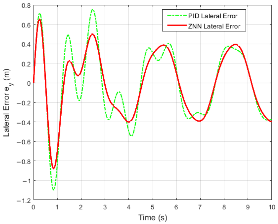
Comment on
Figure 3: Further analysis of the lateral tracking error over time reveals that as time linearly progresses, the PID controller exhibits an unavoidable periodic harmonic oscillation. This yields a min-max error fluctuation between approximately −1.1 m and +0.8 m, which significantly breaches the expected safe boundary. This result clearly illustrates the inherent “feedback lag” limitation of traditional linear feedback mechanisms when handling continuously alternating time-varying commands. In contrast, the ZNN controller effectively suppresses these periodic fluctuations, confining the min-max error within a much narrower band (−0.9 m to +0.6 m) and keeping the error dynamically locked much closer to the zero mark, demonstrating a superior capability to suppress nominal dynamic tracking errors.
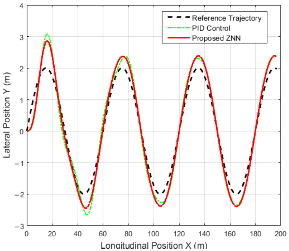
Comment on
Figure 4: Correspondingly, in the sinusoidal trajectory tracking diagram, as the horizontal axis advances, the actual lateral displacement under PID control exhibits significant phase lag and visible amplitude overshoot at dynamic reversals such as peaks and troughs. Conversely, the spatial trajectory of the proposed ZNN controller closely tracks the desired sinusoidal reference curve. This visual evidence confirms that the algorithmic mitigation of phase lag effectively translates into significantly improved macroscopic tracking fidelity without amplitude discontinuity.
4.2.2. Scenario 2: Fault-Tolerant Trajectory Tracking Subject to a Single-Actuator Fault
Pre-test Expectations: During a sudden single-motor failure, the primary control objective is to maintain the post-fault lateral error as close to the nominal expected value (0 m) as possible, preventing finite-time divergence and ensuring the vehicle remains within the safe lane boundaries.
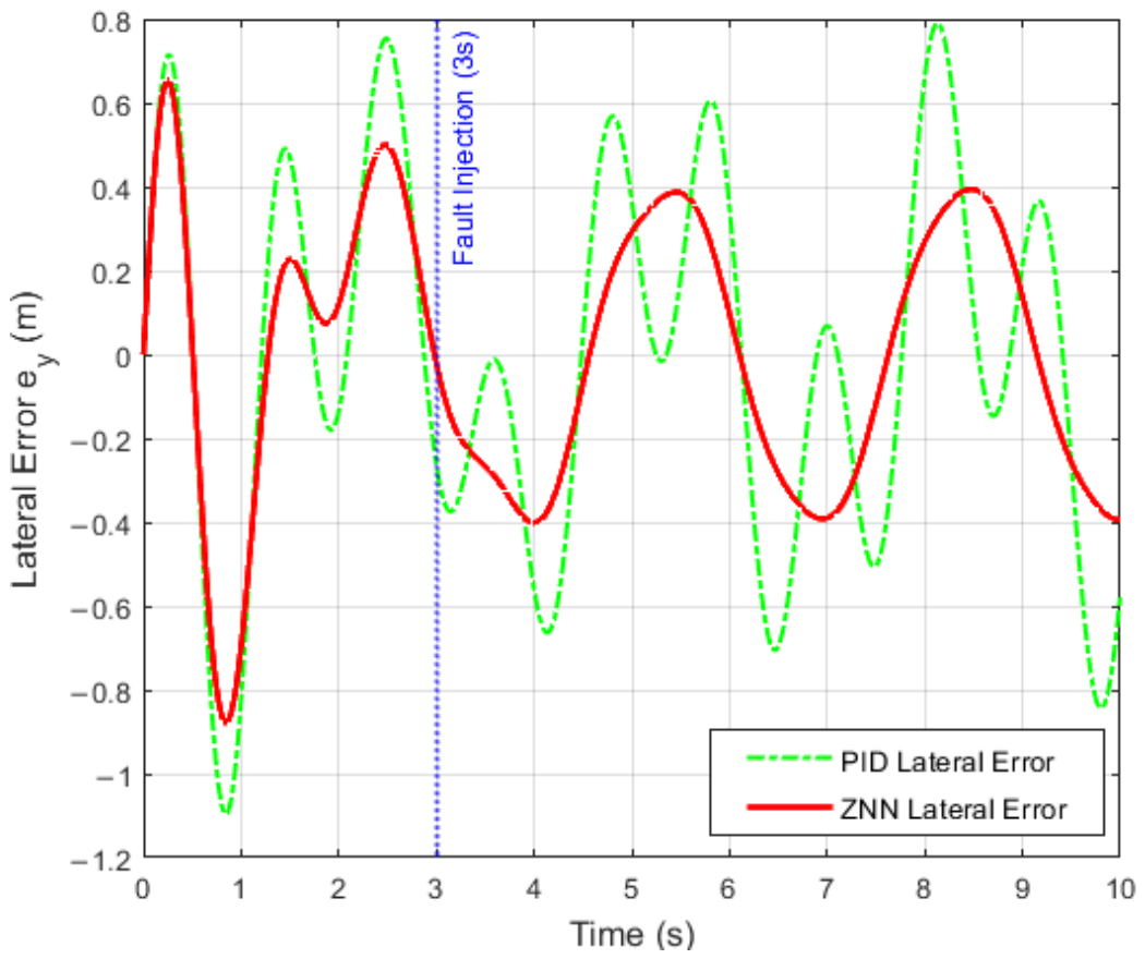
Comment on
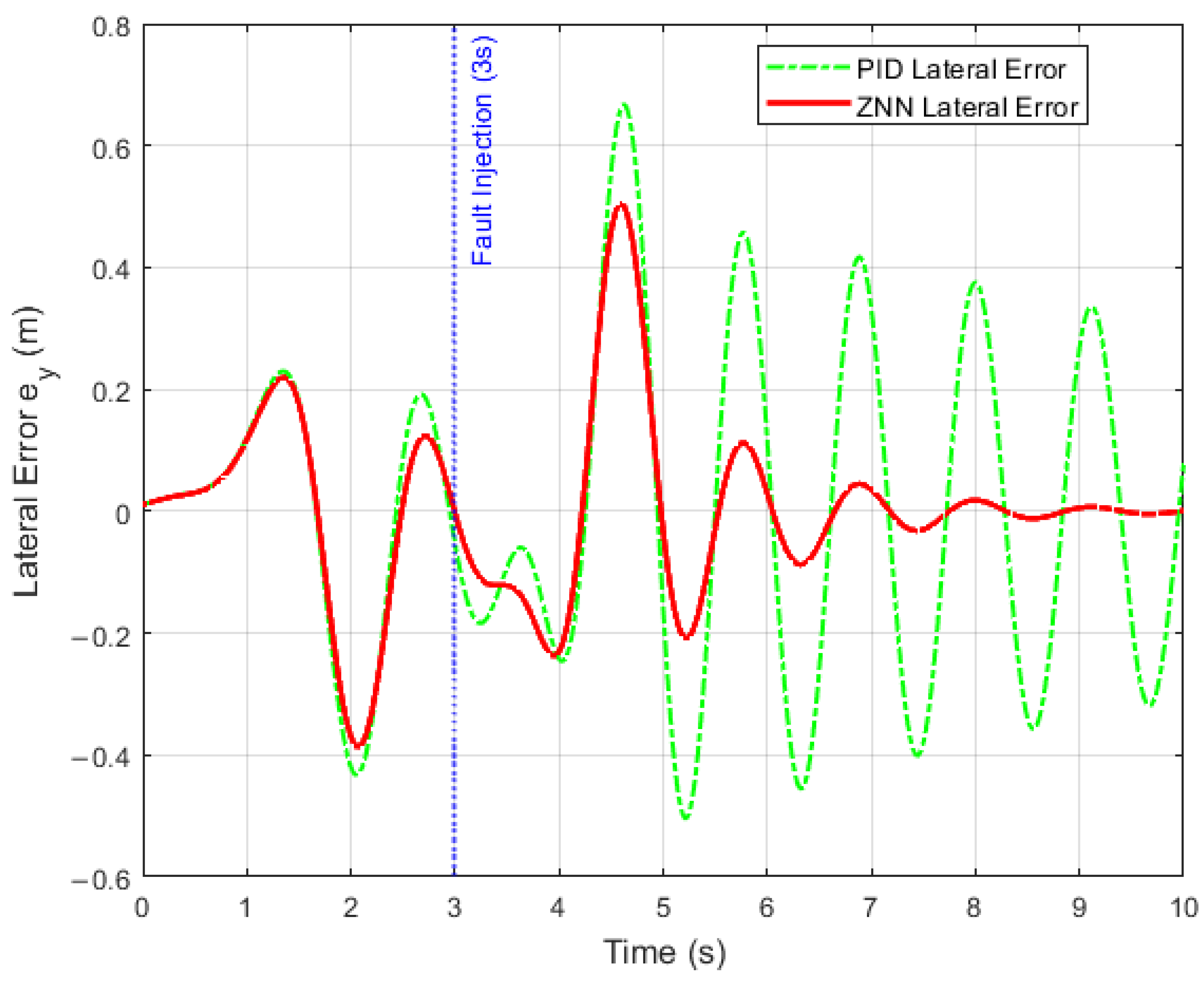
Figure 5: Quantitative analysis of the lateral tracking error over time precisely illustrates the underlying dynamic differences. When the fault is injected at exactly t = 3.0 s, the PID controller loses its dynamic suppression capability. It exhibits an immediate exponential error spike, rapidly exceeding the 0.8-m danger limit, with subsequent wild oscillations approaching a min-max peak of −1.2 m. This clearly highlights the vulnerability of traditional linear feedback when subjected to nonlinear abrupt shocks. Conversely, the ZNN error axis experiences only a negligible, extremely brief transient fluctuation under this strong physical shock. It is instantly and forcibly pulled back by the instantaneous reconstruction mechanism of the Jacobian pseudo-inverse matrix within the algorithm, successfully maintaining strict safety bounds.
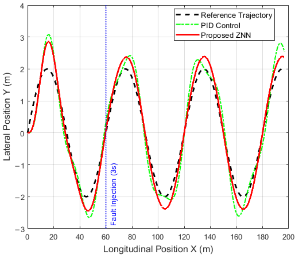
Comment on
Figure 6: The global spatial trajectory visually confirms this quantitative difference. After crossing the critical point of fault injection, the PID-controlled vehicle loses its ability to overcome the nonlinear restoring torque due to the instantaneous halving of the underlying steering actuator torque. This results in a divergent trend that severely deviates from the desired sine wave, eventually running off the track boundary. In contrast, the ZNN trajectory remains remarkably smooth and closely adheres to the desired reference curve post-fault. This conclusively demonstrates that the microsecond-level fault-tolerant execution at the actuator layer directly minimizes the impact of severe hardware faults, effectively guaranteeing uninterrupted vehicle safety at the macroscopic driving layer.
4.3. Simulation Analysis of Double Lane Change Steering Conditions
The Dual Lane Change (DLC) test is an internationally recognized stringent testing standard for evaluating the high-speed emergency obstacle avoidance capabilities of autonomous vehicles. The vehicle must complete two sharp lane change maneuvers in opposite directions within a short period.
4.3.1. Scenario 1: Conventional Trajectory Tracking Under Motor Failure Conditions
Pre-test Expectations: The Double Lane Change (DLC) maneuver represents a severe, highly dynamic emergency evasive scenario. While the expected ideal lateral tracking error remains 0 m, the aggressive and rapid steering inputs make it extremely challenging. Maintaining a tight error boundary is critical here to prevent vehicle spin or obstacle collision during the high-frequency lane switches.
Comment on
Figure 7: By analyzing the lateral tracking error over time, precise micro-source tracing of the system’s dynamic response can be performed. As the time axis crosses the high-frequency lane change phases featuring sharp steering wheel turns, the PID controller struggles with the rapid directional changes. It exhibits several obvious error peaks with a min-max fluctuation bounded between approximately −0.55 m and +0.66 m. This clearly illustrates the inherent “slow response” limitation of traditional pure linear feedback control when dealing with nonlinear rapid-change commands. In contrast, the proposed ZNN framework effectively suppresses these transient spikes, tightly confining the min-max error within a vastly superior range of −0.25 m to +0.29 m. The ZNN error amplitude remains firmly suppressed near the zero mark throughout the entire time axis.
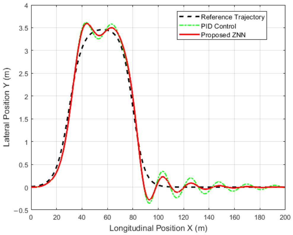
Comment on
Figure 8: Correspondingly, the global spatial trajectory illustrates that as the vehicle advances, the PID control yields noticeable dynamic tracking lag and outward trajectory overshoots when experiencing the two sharp lane change turns (i.e., abrupt curvature change points). The ZNN trajectory, however, exhibits extremely high tracking fidelity to the expected DLC reference curve. From the perspective of the underlying control manifold, this difference in dynamic evolution rigorously demonstrates that the ZNN framework, utilizing its unique time-varying partial derivative prediction and compensation mechanism, significantly mitigates the dynamic phase lag of the system during continuous emergency maneuvers.
4.3.2. Scenario 2: Fault-Tolerant Tracking for Single Motor Failure
Pre-test Expectations: Experiencing a sudden motor failure during the most aggressive lateral acceleration phase of a DLC maneuver poses a severe risk of total vehicle control loss. The rigorous expectation here is for the controller to instantaneously reallocate torque to prevent trajectory divergence and avoid a catastrophic crash.
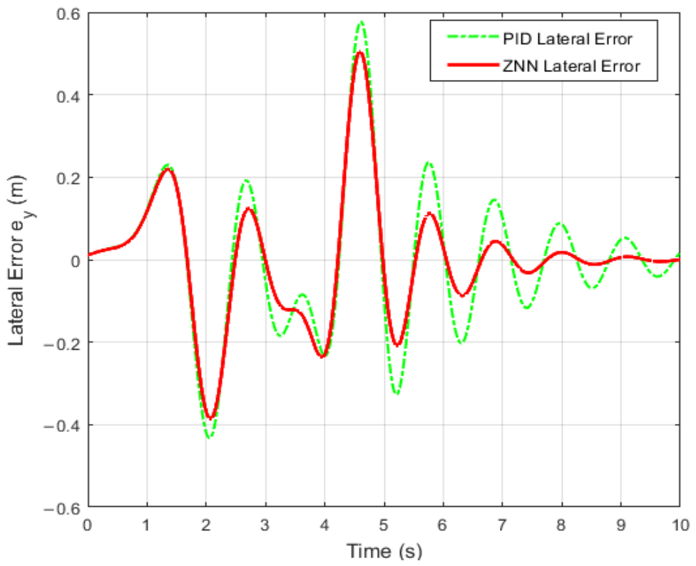
Comment on
Figure 9: When the severe fault is injected during the dynamic lane change, the PID controller fails to suppress the disturbance. Its error spikes dangerously, pushing the min-max boundaries well beyond acceptable safety thresholds (with absolute errors rapidly expanding). In sharp contrast, the ZNN controller experiences only a minimal transient disturbance. Thanks to the instantaneous Jacobian pseudo-inverse reallocation, it forcibly pulls the tracking error back, maintaining strict bounds with the maximum absolute error securely locked at 0.29 m.
Comment on
Figure 10: The macroscopic vehicle trajectory visually confirms this stark quantitative difference. The PID-controlled vehicle deviates significantly from the target emergency lane, which would inevitably result in a collision in a real-world scenario. The ZNN-controlled vehicle seamlessly and safely completes the entire double lane change maneuver despite the severe actuator loss, conclusively proving its vital role in ensuring dynamic driving safety under extreme conditions.
4.4. Error Quantitative Evaluation and Index Analysis
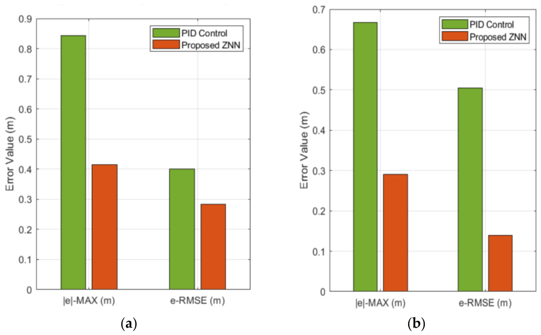
To further quantify the superiority of the proposed control strategy, the maximum absolute value (|e|-MAX) and root mean square error (e-RMSE) of the lateral tracking error during the period after the fault occurred under two operating conditions were extracted as core evaluation indicators, Comment on
Figure 11.
As detailed in
Table 2, comparative data shows that when faced with a fatal failure of a single motor, the performance of traditional PID control methods deteriorates rapidly, with its e-RMSE approaching the dangerous threshold under both sinusoidal and DLC conditions. In contrast, the ZNN fault tolerant controller designed in this paper reduces the |e|-MAX by more than 50% compared to PID, and the e-RMSE by up to 72%. This significant quantitative improvement fully demonstrates that the proposed performance preserving ZNN redundant cooperative control strategy plays a decisive role in improving the trajectory tracking accuracy and driving safety of autonomous vehicles when dealing with multiple dynamic uncertainties and sudden actuator failures.
It must be strongly emphasized that the severe performance degradation of the PID controller observed during the fault injection phase is not a consequence of suboptimal parameter tuning. Rather, it exposes the inherent structural limitations of conventional linear error-feedback mechanisms. A traditional PID controller lacks the endogenous awareness of the actuator’s Jacobian matrix dimension changes. Consequently, when a motor suddenly loses power, the PID algorithm blindly attempts to increase the global command without adjusting the redundancy allocation ratio, failing to overcome the highly nonlinear self-aligning torque. In contrast, the proposed ZNN actively modifies the control manifold via the Jacobian pseudo-inverse, proving that its superiority stems from mathematical structural advantages rather than baseline degradation.
Detailed Analysis of e-RMSE and Industry Standards: While the maximum absolute error defines the absolute safety boundary to prevent catastrophic lane departure, the Root Mean Square Error (e-RMSE) serves as a critical indicator of sustained control quality. In practical automotive engineering, e-RMSE directly quantifies the continuous spatial variance and the sustained “ping-pong” oscillation energy of the vehicle within the lane.
According to current industrial standards for mass-production Autonomous Lane Keeping Systems (ALKS), maintaining passenger comfort and smooth trajectory tracking requires the lateral tracking e-RMSE to be strictly bounded below 0.15 to 0.20 m under dynamic maneuvers. As detailed in
Table 2, the traditional PID controller exhibits an e-RMSE that significantly exceeds this industrial comfort threshold during complex scenarios (such as the Double Lane Change), indicating severe control effort chattering and noticeable in-lane oscillation. In stark contrast, the proposed ZNN controller drastically compresses the e-RMSE to a fraction of the PID’s value (consistently well below the 0.15-m ideal standard). This profound reduction in e-RMSE conclusively proves that the instantaneous pseudo-inverse reallocation mechanism not only guarantees macroscopic safety during fault shocks but also meets the stringent ride-comfort and smoothness standards required for real-world autonomous driving applications.
5. Conclusions
This research successfully pioneers the cross-domain application of ZNN to highly nonlinear dual-motor SBW systems. By effectively handling continuous and dynamic self-aligning torques, the proposed framework securely bridges the gap between microscopic actuator failures and macroscopic vehicle safety. The main findings and contributions of this study are summarized as follows:
Mathematical Guarantee of Safety Boundaries: By embedding a prescribed performance transformation directly into the neural network topology, the system mathematically guarantees that the lateral tracking error remains strictly within predefined safety limits, even during the precise millisecond of a severe single-motor failure.
Transient-Free Torque Reallocation: Demonstrating superior real-time computational efficiency, the integrated Jacobian pseudoinverse mechanism leverages the continuous evolutionary nature of ZNN. Unlike conventional discrete logic-based fault-tolerant strategies, this continuous approach achieves seamless, transient-free torque compensation without complex switching logic.
Enhanced Mechanical Durability and Ride Comfort: Simulation comparisons confirm that the proposed framework effectively eliminates the severe mechanical chattering and torque spikes typically generated during control command reconstruction. This critical characteristic not only protects the physical lifespan of the steering actuators but also ensures the continuity of the vehicle’s lateral acceleration from the ground up—ultimately guaranteeing global path fidelity while optimizing ride comfort and dynamic stability during autonomous driving.
Future Work: While this study successfully establishes the mathematical framework, topological safety boundaries, and computational feasibility of the ZNN architecture under worst-case total failures and extreme dynamic loads, pure simulation represents only the foundational Model-in-the-Loop (MIL) phase of the standard automotive V-model. To address the inherent limitations of simulation in capturing physical hardware delays, friction nonlinearities, and sensor noise, our ongoing research will transition to rigorous Hardware-in-the-Loop (HIL) bench testing. We will deploy the proposed algorithm onto a physical automotive electronic control unit driving a real dual-motor steering rack. Furthermore, to comprehensively verify the algorithm’s real-world engineering robustness across broader operational design domains, future validations will encompass complex stochastic edge cases. These expanded scenarios will include urban traffic interactions, varying environmental disturbances, asymmetric road friction, intermittent electrical faults, partial actuator degradation, sensor measurement drift, and varying communication delays.
Broader Applications and Specific Domains: Beyond the immediate scope of passenger autonomous vehicles, the foundational fault-tolerant framework established in this manuscript holds significant potential for broader industrial applications. The real-time ZNN-based dynamic reallocation strategy provides a highly adaptable algorithmic template that can be directly extended to other safety-critical, over-actuated systems. Specific domains that can extensively utilize this methodology include heavy-duty commercial transport (such as autonomous electric trucks and articulated buses) where steering failures pose catastrophic payload and public safety risks, Unmanned Ground Vehicles (UGVs) operating in extreme environments (e.g., automated mining or planetary exploration) where physical maintenance is impossible and hardware redundancy is vital, and the aerospace sector for fault-tolerant aircraft SBW taxiing systems. Ultimately, this research provides a scalable mathematical foundation for enhancing the fail-operational resilience of any multi-actuator coupled mechanism.
Author Contributions
D.Z., L.Y., M.X.—Methodology; D.Z., L.Y., M.X., J.S., Y.H., J.Y.—original draft; D.Z., L.Y., A.O., L.R., D.M.—review and editing; D.Z., L.Y., M.X., J.S., Y.H., J.Y.—validations. All authors have read and agreed to the published version of the manuscript.
Funding
This work was supported in part by the National Natural Science Foundation of China (Grant No. 52462053), and the Key Research and Development Project of Jiangxi Province (Grant No. 20261BCE310045).
Data Availability Statement
The original contribution of this research is included in the paper. For further inquiries, please contact the first author.
Conflicts of Interest
Min Xiong is employees of Jiangling Group Electric Vehicle Corporation (China), Nanchang, China. Jiawen Sun is employees of Jiangling Motors Corporation (China), Nanchang, China. The remaining authors declare that the research was conducted in the absence of any commercial or financial relationships that could be construed as a potential conflict of interest.
References
- Qu, X.; Chen, H.; Zhang, J.; Wang, W. A Review of Key Technologies for Vehicle Steer-by-Wire Systems. J. Chongqing Univ. Technol. (Nat. Sci.) 2023, 37, 74–84. [Google Scholar]
- Zhao, W.; Zhang, H.; Zou, S.; Li, J.; Wang, Q.; Liu, Y. A review of control technology for steer-by-wire systems. J. Automot. Saf. Energy Conserv. 2021, 12, 18–34. [Google Scholar]
- Leng, B.; Yu, R.; Tu, C.; Xiong, L.; Eichberger, A.; Li, Z. Seamless Overtaking Maneuvers for Automated Driving: Integrated Motion Planning Based on Hybrid Model Predictive Control. IEEE Trans. Ind. Electron. 2026. early access. [Google Scholar] [CrossRef]
- Li, Z.; Hu, J.; Leng, B.; Xiong, L.; Xu, P. Safety Enhanced Reinforcement Learning for Autonomous Driving: Dare to Make Mistakes to Learn Faster and Better. IEEE Trans. Intell. Transp. Syst. 2026. early access. [Google Scholar] [CrossRef]
- Jin, G.; Li, Z.; Leng, B.; Han, W.; Xiong, L.; Sun, C. Hybrid Action-Based Reinforcement Learning for Multiobjective Compatible Autonomous Driving. IEEE Trans. Neural Netw. Learn. Syst. 2026. early access. [Google Scholar]
- Li, Z.; Hu, J.; Leng, B.; Xiong, L.; Fu, Z. An Integrated of Decision Making and Motion Planning Framework for Enhanced Oscillation-Free Capability. IEEE Trans. Intell. Transp. Syst. 2024, 25, 5718–5732. [Google Scholar]
- Wang, S.; Shi, G.; Sang, D.; Zhang, H.Q. Sliding Mode Synchronization Control and Hardware-in-the-Loop Simulation for a Dual-Motor Steer-by-Wire System. China J. Highw. Transp. 2021, 34, 61–69. [Google Scholar]
- Zou, S.; Zhao, W.; Wang, C. Tracking and synchronization control strategy of vehicle dual-motor steer-by-wire system via super-twisting SOSMC and MDCS. Mech. Syst. Signal Process. 2022, 183, 109638. [Google Scholar]
- Shi, G.B.; Guo, C.; Wang, S.; Liu, T.Y. Angle Tracking and Fault-Tolerant Control of Steer-by-Wire System with Dual Three-Phase Motor for Autonomous Vehicle. IEEE Trans. Intell. Transp. Syst. 2024, 25, 5842–5853. [Google Scholar]
- Shao, B.; Liu, L.; Hu, M. Improved Sliding Mode Control Based on Active Disturbance Rejection Control for Load Torque Observation of Permanent Magnet Synchronous Motors. J. Xi’an Jiaotong Univ. 2024, 58, 204–211. [Google Scholar]
- Shi, S.; Guo, L.; Chang, Z.; Zhao, C.; Chen, P. Current controller based on active disturbance rejection control with parameter identification for PMSM servo systems. IEEE Access 2023, 11, 46882–46891. [Google Scholar] [CrossRef]
- Ding, J.; Wang, S. Finite-Time Extended State Observer-Based Tracking and Synchronization Control for Dual-Motor System. Control. Eng. 2025. early access. [Google Scholar]
- Miao, Z.; He, Y.; Li, H.; Wang, Y. Dual-PMSM speed synchronization control based on unified prediction model. J. Meas. Sci. Instrum. 2023, 14, 315–323. [Google Scholar] [CrossRef]
- Yang, C.; Meng, F.; Zhang, H.; Zhao, J.; Wang, H.; Zhou, L. Optimal coordinated control for speed tracking and torque synchronization of rigidly connected dual-motor systems. IEEE/ASME Trans. Mechatron. 2023, 28, 2609–2620. [Google Scholar] [CrossRef]
- Zhang, Y.; Ling, Y.; Li, S.; Yang, M.; Tan, N. Discrete-time zeroing neural network for solving time-varying Sylvester-transpose matrix inequation via exp-aided conversion. Neurocomputing 2020, 386, 126–135. [Google Scholar]
- Lai, G.; Lin, C.; Ouyang, Y.; Wu, Y.; Xiao, H.; Liu, X. Finite-Time Uncalibrated Visual Servoing for Robotic Manipulators Based on Model-Free Zeroing Neural Networks. IEEE Trans. Autom. Sci. Eng. 2025, 22, 24347–24361. [Google Scholar]
- Zhang, B.; Li, S.; Chen, X.; Mao, Y. A novel zeroing neural model for solving dynamic matrix moore-penrose inverse and its application to visual servoing control of manipulator. IEEE Trans. Instrum. Meas. 2024, 73, 2517213. [Google Scholar] [CrossRef]
| Disclaimer/Publisher’s Note: The statements, opinions and data contained in all publications are solely those of the individual author(s) and contributor(s) and not of MDPI and/or the editor(s). MDPI and/or the editor(s) disclaim responsibility for any injury to people or property resulting from any ideas, methods, instructions or products referred to in the content. |




 ,
,