Enhancing Phase Change Material Efficiency in Wavy Trapezoidal Cavities: A Numerical Investigation of Nanoparticle Additives

 ,
,  , , ,
, , ,  ,
,  and
and
Abstract
1. Introduction
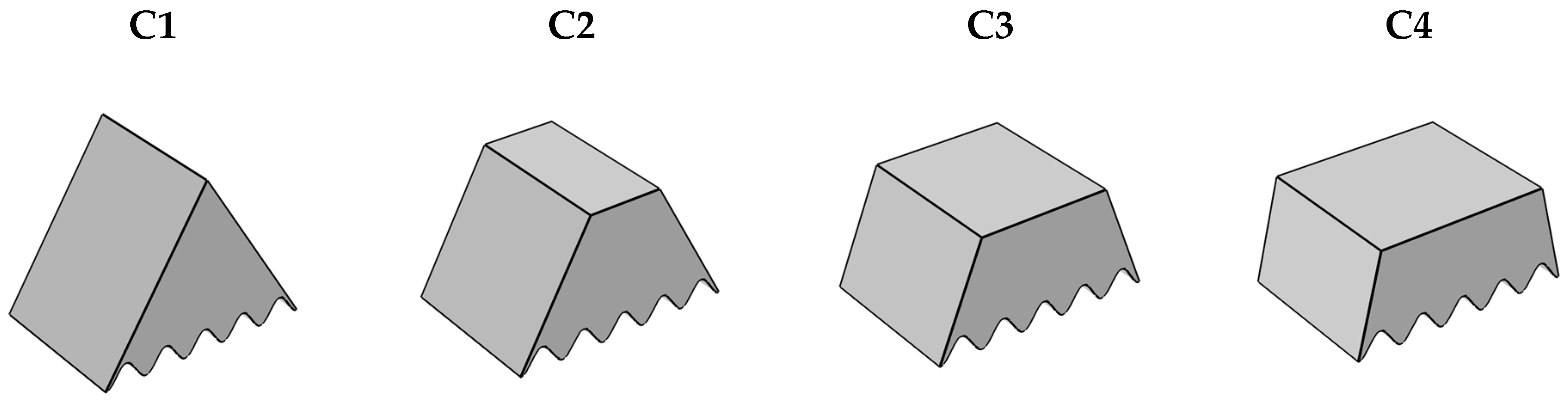
2. Issue Overview
3. Mathematical Model
3.1. The Assumptions
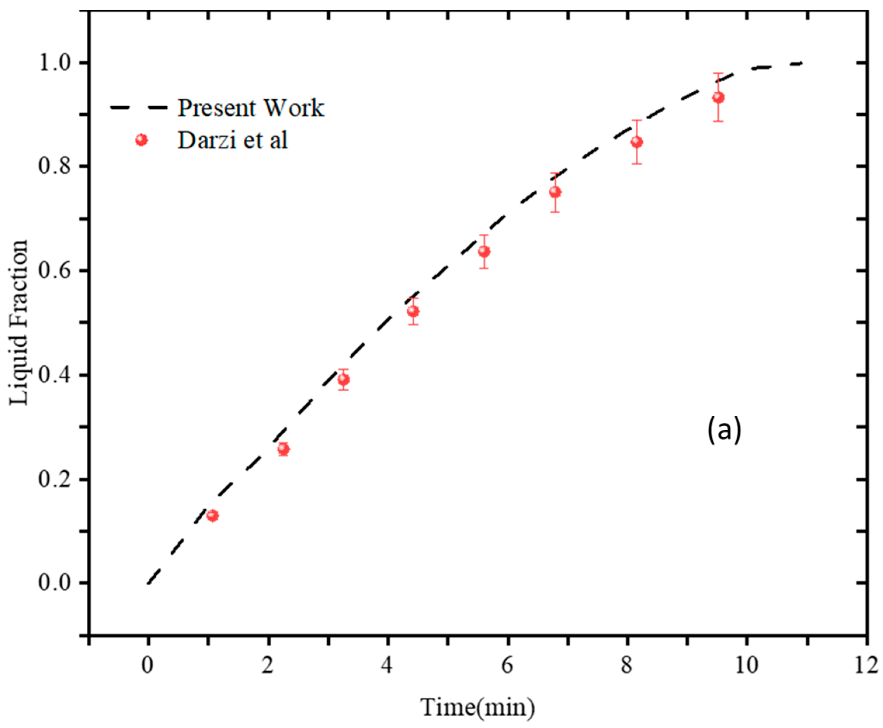
3.2. Numerical Validation
4. Results and Discussion
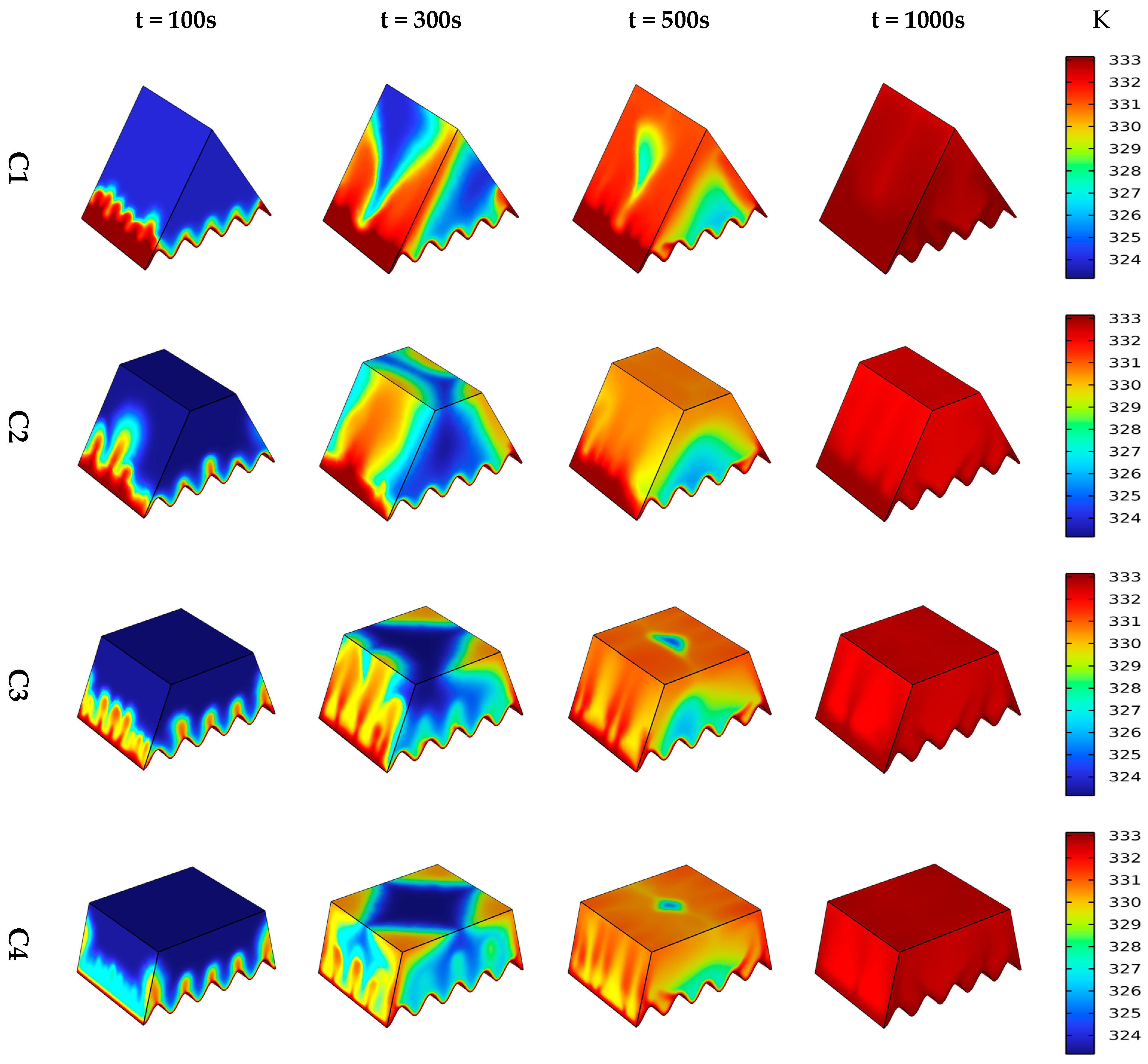
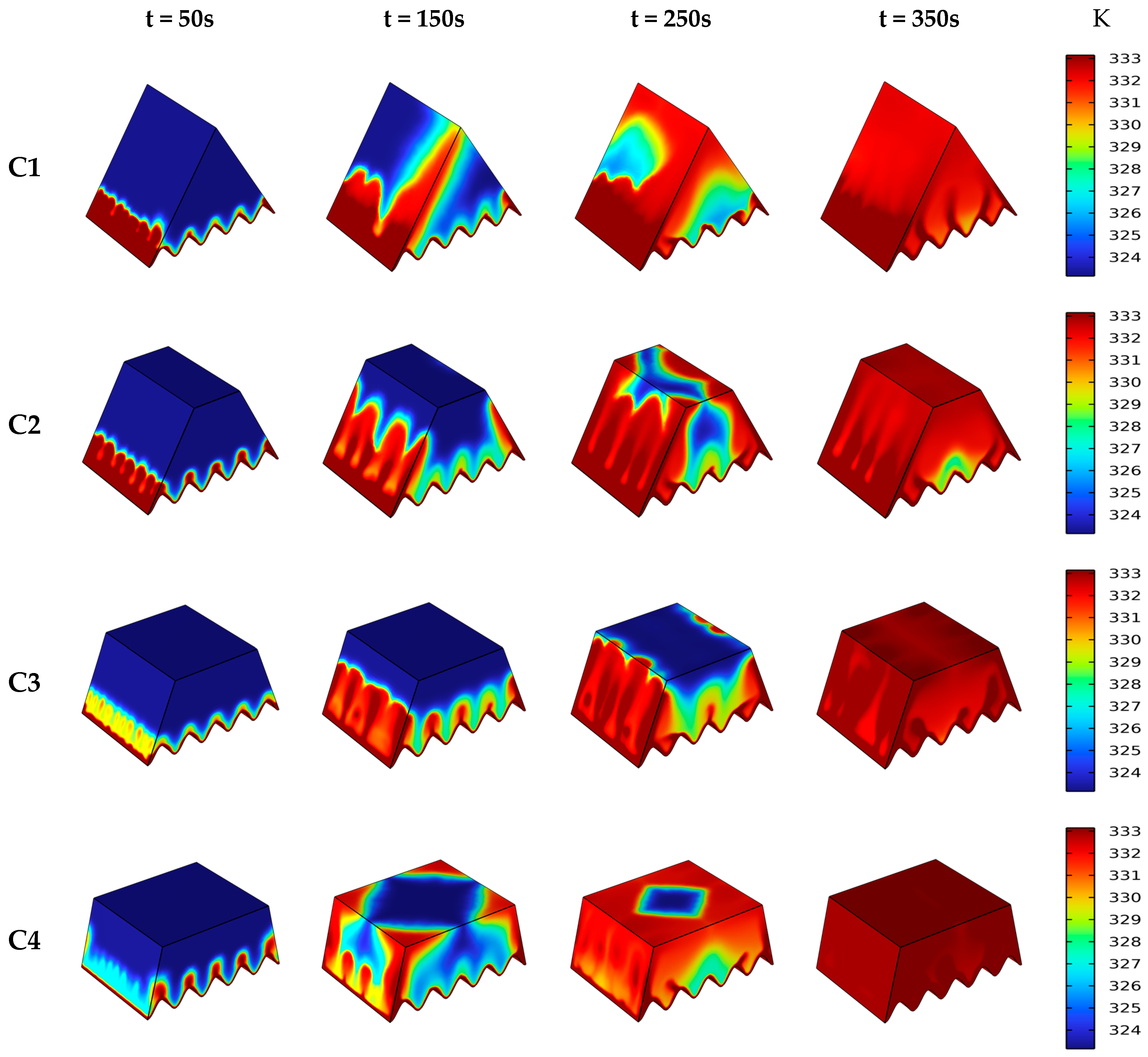
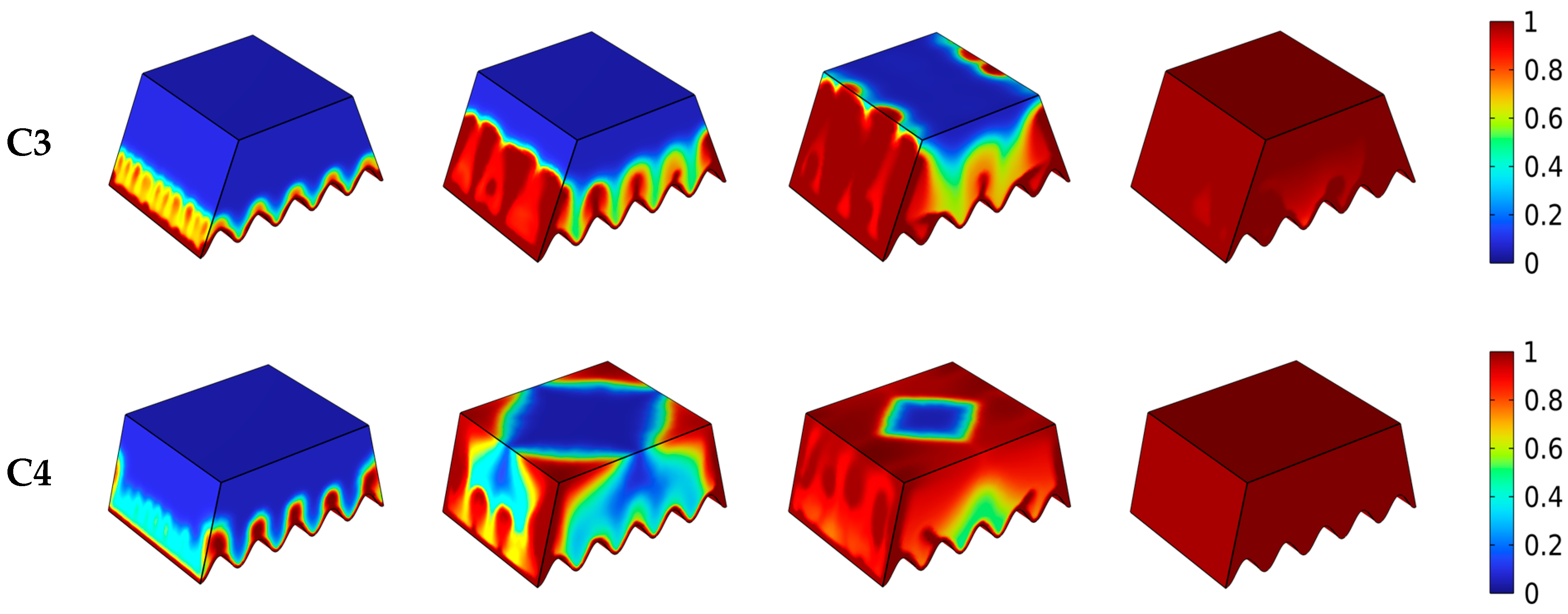
4.1. Influence of Different Heat Source
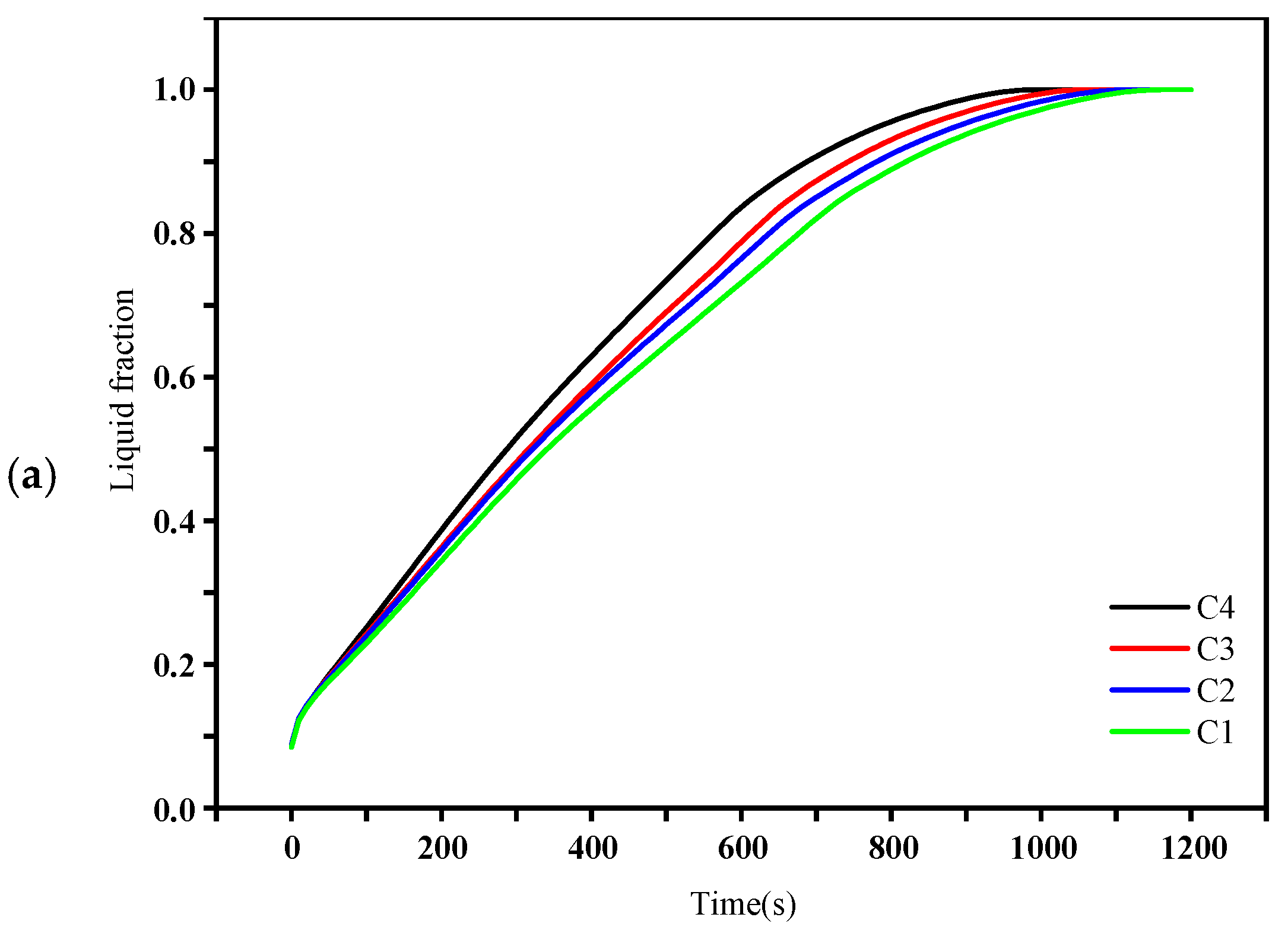
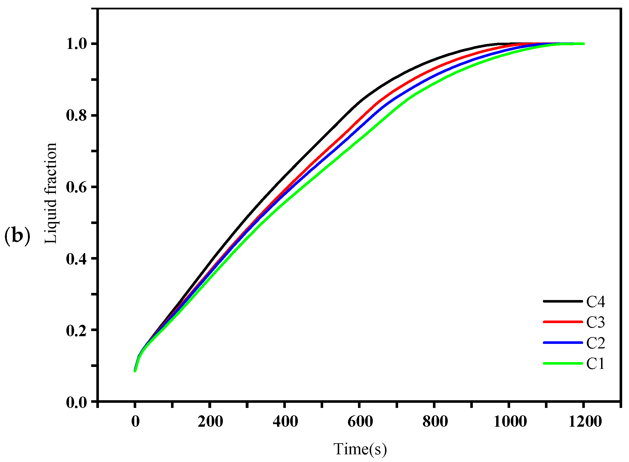
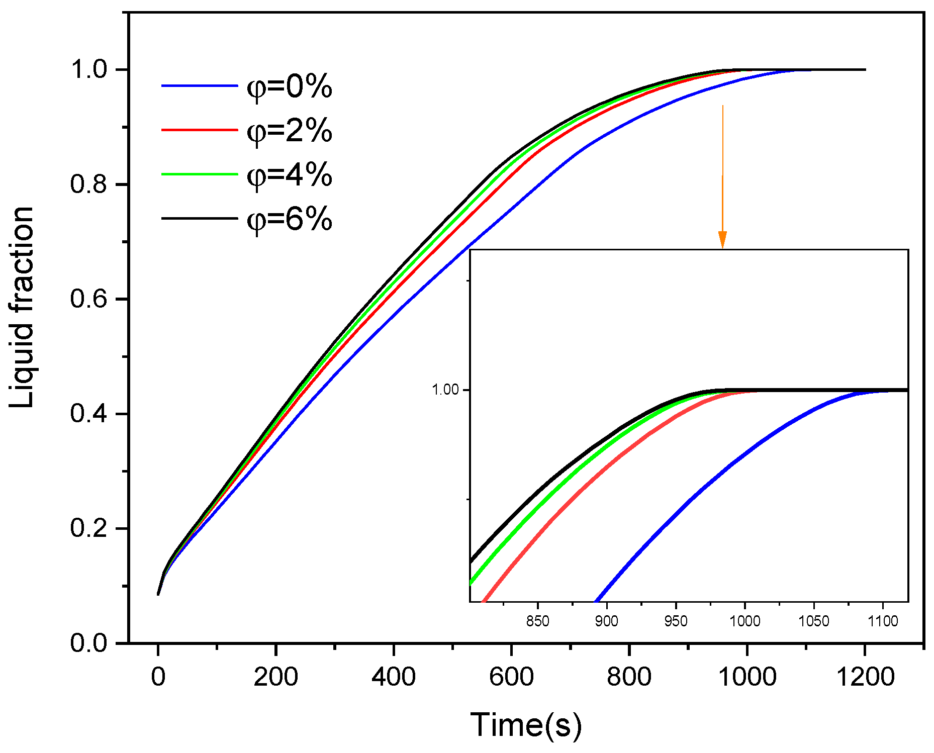
4.2. Liquid Fraction
4.3. Nanoparticle Incorporation
4.4. Effect on Energy Storage
5. Conclusions
- The reduction in trapeze height resulted in a significant increase in heat transmission rates and a decrease in melting time by about 4.2%, 9.25%, and 15.13%, respectively, compared to the first example. This is a result of the decrease in the thermal resistance of each unit.
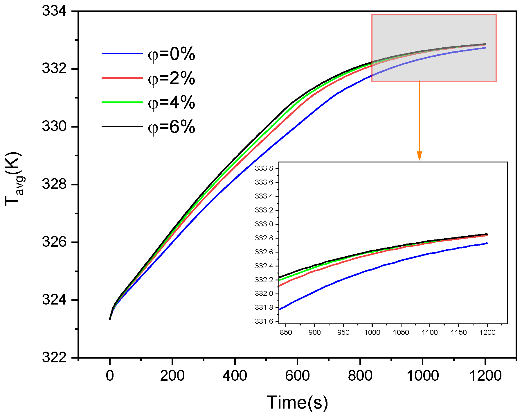
- Increasing the temperature of the large base to 338.15 K instead of 333.15 K can accelerate the charging process by 65.55%. For instance, the storage unit reaches maximum temperatures of 332.85 K and 338.12.7 K after 1200 s when the heat source temperatures are set to 333.15 K and 338.15 K.
- Integrating nanoparticles with PCM can enhance the thermal conductivity efficiency during the process of melting. Utilizing a nanoparticle concentration of 4 vol% may result in a decrease of around 9.8% in melting time, while a concentration of 6 vol% can produce a reduction of approximately 10.71%.
- Experimental research of great scale needs execution to validate current numerical models alongside gathering empirical thermal behavior data when exposed to different operating parameters.
- Investigation of hybrid PCM–nanoparticle composites to mitigate the height trade-off.
Author Contributions
Funding
Data Availability Statement
Conflicts of Interest
Abbreviations
| AR | aspect ratio |
| HTF | heat transfer fluid |
| LHTESS | latent heat thermal energy storage system |
| MSE | mean squared error |
| NePCM | nano-enhanced PCM |
| PCM | phase change materials |
| PW | paraffin wax |
| RMSE | root mean squared error |
| TES | storage of thermal energy |
| Nomenclature | |
| area (m2) | |
| specific heat (J/kgK) | |
| height of trapezoidal cavity (cm) | |
| gravitational acceleration (ms−2) | |
| total enthalpy (kJ/kg) | |
| sensible enthalpy (kJ/kg) | |
| enthalpy reference (kJ/kg) | |
| thermal conductivity (W/m K) | |
| Boltzmann constant | |
| latent heat of fusion (kJ/kg) | |
| p | pressure (Pa) |
| temperature (K) | |
| initial temperature (K) | |
| liquid temperature (K) | |
| melting point (K) | |
| solid temperature (K) | |
| time (s) | |
| velocity vector (m/s) | |
| velocity in the x-direction (ms−1) | |
| velocity in the y-direction (ms−1) | |
| velocity in the z-direction (ms−1) | |
| lower horizontal width (m) | |
| upper horizontal width (m) | |
| side width (m) | |
| Greek letters | |
| thermal expansion coefficient (K−1) | |
| liquid fraction | |
| latent heat (kJ/kg) | |
| transition temperature range (K) | |
| regularization parameter | |
| porosity function | |
| dynamic viscosity (Pa.s) | |
| density (kg/m3) | |
| nanoparticle volume fraction (concentration) | |
| Subscripts | |
| liquid state | |
| mush | mushy region |
| nanoparticle | |
| ref | reference |
| solid state |
References
- Jeong, D.; Hwang, S.; Kim, J.; Yu, H.; Park, E. Public perspective on renewable and other energy resources: Evidence from social media big data and sentiment analysis. Energy Strategy Rev. 2023, 50, 101243. [Google Scholar] [CrossRef]
- Net Zero by 2050: A Roadmap for the Global Energy Sector; International Energy Agency: Paris, France, 2021; Available online: https://www.iea.org/reports/net-zero-by-2050 (accessed on 30 April 2025).
- Su, H.; Lin, P.; Lu, H.; Chen, Y. Efficient solar-thermal conversion and thermal energy storage towards personal thermal management and thermoelectric power generation enabled by massive screen printing of carbon nanotube dopped energy storage gels. J. Energy Stor. 2024, 76, 109782. [Google Scholar] [CrossRef]
- Wang, G.; Zhang, Z.; Lin, J. Multi-energy complementary power systems based on solar energy: A review. Renew. Sustain. Energy Rev. 2024, 199, 114464. [Google Scholar] [CrossRef]
- Belazreg, A.; Abderrahmane, A.; Qasem, N.A.; Sene, N.; Mohammed, S.; Younis, O.; Guedri, K.; Nasajpour-Esfahani, N.; Toghraie, D. Effect of Y-shaped fins on the performance of shell-and-tube thermal energy storage unit. Case Stud. Therm. Engin. 2022, 40, 102485. [Google Scholar] [CrossRef]
- Poyyamozhi, N.; Bibin, C.; Kumar, S.S.; Renugadevi, P. Energy storage investigation of solar pond integrated with PCM and nanoparticles during winter season in Chennai. J. Energy Stor. 2023, 73, 108704. [Google Scholar] [CrossRef]
- Mofijur, M.; Mahlia, T.M.I.; Silitonga, A.S.; Ong, H.C.; Silakhori, M.; Hasan, M.H.; Putra, N.; Rahman, S.A. Phase change materials (PCM) for solar energy usages and storage: An overview. Energies 2019, 12, 3167. [Google Scholar] [CrossRef]
- Gautam, A.; Saini, R.P. A review on technical, applications and economic aspect of packed bed solar thermal energy storage system. J. Energy Stor. 2020, 27, 101046. [Google Scholar] [CrossRef]
- Himran, S.; Suwono, A.; Mansoori, G.A. Characterization of alkanes and paraffin waxes for application as phase change energy storage medium. Energy Sources 1994, 16, 117–128. [Google Scholar] [CrossRef]
- Hadjieva, M.; Kanev, S.; Argirov, J. Thermophysical properties of some paraffins applicable to thermal energy storage. Sol. Energy Mater. Sol. Cells 1992, 27, 181–187. [Google Scholar] [CrossRef]
- Ukrainczyk, N.; Kurajica, S.; Sipu, J. Thermophysical comparison of five commercial paraffin waxes as latent heat storage materials. Chem. Biochem. Engin. Quart. 2010, 24, 129–137. Available online: http://silverstripe.fkit.hr/cabeq/past-issues/article/240 (accessed on 30 April 2025).
- Lamosa, R.A.; Motovoy, I.; Khliiev, N.; Nikulin, A.; Khliyeva, O.; Moita, A.S.; Krupanek, J.; Grosu, Y.; Zhelezny, V.; Moreira, A.L.; et al. Tetralin+ C60 solutions for thermal management of flat-plate PV/T collector. Energy Convers. Manag. 2021, 248, 114799. [Google Scholar] [CrossRef]
- Magendran, S.S.; Khan, F.S.A.; Mubarak, N.M.; Vaka, M.; Walvekar, R.; Khalid, M.; Abdullah, E.C.; Nizamuddin, S.; Karri, R.R. Synthesis of organic phase change materials (PCM) for energy storage applications: A review, Nano-Struct. NanoObjects 2019, 20, 100399. [Google Scholar] [CrossRef]
- Kruzel, M.; Bohdal, T.; Dutkowski, K.; Radchenko, M. The effect of microencapsulated PCM slurry coolant on the efficiency of a shell and tube heat exchanger. Energies 2022, 15, 5142. [Google Scholar] [CrossRef]
- Cuevas-Diarte, M.À.; Oonk, H.A.J. (Eds.) Molecular Mixed Crystals; Springer: Cham, Switzerland, 2021; p. 44. [Google Scholar] [CrossRef]
- Wang, K.W.; Yan, T.; Pan, W.G. Optimization strategies of microencapsulated phase change materials for thermal energy storage. J. Energy Stor. 2023, 68, 107844. [Google Scholar] [CrossRef]
- Zheng, H.; Zhang, Z.; Tian, G.; Zeng, S.; Lv, Z.; Sun, J. Study on performance of carbon nanotube composite phase change cold storage sphere with annular fins. J. Energy Stor. 2024, 78, 110074. [Google Scholar] [CrossRef]
- Gadhave, P.; Pathan, F.; Kore, S.; Prabhune, C. Comprehensive review of phase change material based latent heat thermal energy storage system. Int. J. Ambient Energy 2022, 43, 4181–4206. [Google Scholar] [CrossRef]
- Varthani, A.J.; Shasthri, S.; Baljit, S.; Kausalyah, V. A systematic review of metal foam and heat pipe enhancement in Latent Heat Thermal Energy Storage system. J. Energy Stor. 2022, 56, 105888. [Google Scholar] [CrossRef]
- Arıcı, M.; Tütüncü, E.; Kan, M.; Karabay, H. Melting of nanoparticle-enhanced paraffin wax in a rectangular enclosure with partially active walls. Int. J. Heat Mass Transf. 2017, 104, 7–17. [Google Scholar] [CrossRef]
- Akhmetov, B.; Navarro, M.E.; Seitov, A.; Kaltayev, A.; Bakenov, Z.; Ding, Y. Numerical study of integrated latent heat thermal energy storage devices using nanoparticle-enhanced phase change materials. Sol. Energy 2019, 194, 724–741. [Google Scholar] [CrossRef]
- Thonon, M.; Fraisse, G.; Zalewski, L.; Pailha, M. Simultaneous charging and discharging processes in latent heat thermal energy storage: A review. Therm. Sci. Engin. Prog. 2023, 47, 102299. [Google Scholar] [CrossRef]
- Qasem, N.A.; Belazreg, A.; Khetib, Y.; Abderrahmane, A.; Homod, R.Z.; Younis, O.; Rawa, M. Effect of novel fin distribution on the melting process of thermal storage units. Appl. Therm. Engin. 2024, 243, 122547. [Google Scholar] [CrossRef]
- Shrivastava, A.; Chakraborty, P.R. Shell-and-tube latent heat thermal energy storage (ST-LHTES). In Advances in Solar Energy Research; Tyagi, H., Agarwal, A.K., Chakraborty, P.R., Powar, S., Eds.; Springer Nature Singapore Pte Ltd.: Singapore, 2019; pp. 395–441. [Google Scholar] [CrossRef]
- Wang, Y.; Zadeh, P.G.; Duong, X.Q.; Chung, J.D. Optimizing fin design for enhanced melting performance in latent heat thermal energy storage systems. J. Energy Stor. 2023, 73, 109108. [Google Scholar] [CrossRef]
- Qasem, N.A.; Abderrahmane, A.; Belazreg, A.; Younis, O.; Homod, R.Z.; Oreijah, M.; Guedri, K. Influence of tree-shaped fins to enhance thermal storage units. Int. Commun. Heat Mass Transf. 2024, 151, 107220. [Google Scholar] [CrossRef]
- Belazreg, A.; Qasem, N.A.; Abderrahmane, A.; Younis, O.; Khetib, Y.; Rawa, M.; Hassan, A.M. Impact of the shape and curvature of fins on a thermal energy storage unit. Case Stud. Therm. Engin. 2023, 51, 103638. [Google Scholar] [CrossRef]
- Zhang, J.; Cao, Z.; Huang, S.; Huang, X.; Han, Y.; Wen, C.; Walther, J.H.; Yang, Y. Solidification performance improvement of phase change materials for latent heat thermal energy storage using novel branch-structured fins and nanoparticles. Appl. Energy 2023, 342, 121158. [Google Scholar] [CrossRef]
- Williams, D.; Peterson, G.P. A review of thermal property enhancements of low-temperature nano-enhanced phase change materials. Nanomaterials 2021, 11, 2578. [Google Scholar] [CrossRef] [PubMed]
- Tofani, K.; Tiari, S. Nano-enhanced phase change materials in latent heat thermal energy storage systems: A review. Energies 2021, 14, 3821. [Google Scholar] [CrossRef]
- Gunjo, D.G.; Jena, S.R.; Mahanta, P.; Robi, P.S. Melting enhancement of a latent heat storage with dispersed Cu, CuO and Al2O3 nanoparticles for solar thermal application. Renew. Energy 2018, 121, 652–665. [Google Scholar] [CrossRef]
- Bondareva, N.S.; Buonomo, B.; Manca, O.; Sheremet, M.A. Heat transfer inside cooling system based on phase change material with alumina nanoparticles. Appl. Therm. Engin. 2018, 144, 972–981. [Google Scholar] [CrossRef]
- Bondareva, N.S.; Buonomo, B.; Manca, O.; Sheremet, M.A. Heat transfer performance of the finned nano-enhanced phase change material system under the inclination influence. Int. J. Heat Mass Transf. 2019, 135, 1063–1072. [Google Scholar] [CrossRef]
- Arasu, A.V.; Mujumdar, A.S. Numerical study on melting of paraffin wax with Al2O3 in a square enclosure. Int. Commun. Heat Mass Transf. 2012, 39, 8–16. [Google Scholar] [CrossRef]
- Paygude, O.R. Thermal energy storage device using paraffin wax as phase change material. i-Manag. J. Mater. Sci. 2020, 8, 22–27. [Google Scholar] [CrossRef]
- Iftikhar, N.; Rehman, A.; Sadaf, H. Theoretical investigation for convective heat transfer on Cu/water nanofluid and (SiO2-copper)/water hybrid nanofluid with MHD and nanoparticle shape effects comprising relaxation and contraction phenomenon. Int. Commun. Heat Mass Transf. 2021, 120, 105012. [Google Scholar] [CrossRef]
- Palmer, B.; Arshad, A.; Yang, Y.; Wen, C. Energy storage performance improvement of phase change materials-based triplex-tube heat exchanger (TTHX) using liquid–solid interface-informed fin configurations. Appl. Energy 2023, 333, 120576. [Google Scholar] [CrossRef]
- Yan, P.; Fan, W.; Yang, Y.; Ding, H.; Arshad, A.; Wen, C. Performance enhancement of phase change materials in triplex-tube latent heat energy storage system using novel fin configurations. Appl. Energy 2022, 327, 120064. [Google Scholar] [CrossRef]
- Han, Y.; Yang, Y.; Mallick, T.; Wen, C. Nanoparticles to enhance melting performance of phase change materials for thermal energy storage. Nanomaterials 2022, 12, 1864. [Google Scholar] [CrossRef]
- Vajjha, R.S.; Das, D.K. Experimental determination of thermal conductivity of three nanofluids and development of new correlations. Int. J. Heat Mass Transf. 2009, 52, 4675–4682. [Google Scholar] [CrossRef]
- Du, Z.; Liu, G.; Huang, X.; Xiao, T.; Yang, X.; He, Y.L. Numerical studies on a fin-foam composite structure towards improving melting phase change. Int. J. Heat Mass Transf. 2023, 208, 124076. [Google Scholar] [CrossRef]
- Li, F.; Huang, X.; Li, Y.; Lu, L.; Meng, X.; Yang, X.; Sundén, B. Application and analysis of flip mechanism in the melting process of a triplex-tube latent heat energy storage unit. Energy Rep. 2023, 9, 3989–4004. [Google Scholar] [CrossRef]
- Xiao, T.; Liu, G.; Guo, J.; Shu, G.; Lu, L.; Yang, X. Effect of metal foam on improving solid–liquid phase change in a multi-channel thermal storage tank. Sustain. Energy Technol. Assess. 2022, 53, 102533. [Google Scholar] [CrossRef]
- Liu, G.; Du, Z.; Xiao, T.; Guo, J.; Lu, L.; Yang, X.; Hooman, K. Design and assessments on a hybrid pin fin-metal foam structure towards enhancing melting heat transfer: An experimental study. Int. J. Therm. Sci. 2022, 182, 107809. [Google Scholar] [CrossRef]
- Xiao, T.; Liu, Z.; Lu, L.; Han, H.; Huang, X.; Song, X.; Yang, X.; Meng, X. LSTM-BP neural network analysis on solid-liquid phase change in a multi-channel thermal storage tank. Engin. Anal. Bound. Elem. 2023, 146, 226–240. [Google Scholar] [CrossRef]
- Huang, X.; Li, F.; Xiao, T.; Guo, J.; Wang, F.; Gao, X.; Yang, X.; He, Y.L. Investigation and optimization of solidification performance of a triplex-tube latent heat thermal energy storage system by rotational mechanism. Appl. Energy 2023, 331, 120435. [Google Scholar] [CrossRef]
- Zhang, J.; Cao, Z.; Huang, S.; Huang, X.; Liang, K.; Yang, Y.; Tian, M.; Akrami, M.; Wen, C. Improving the melting performance of phase change materials using novel fins and nanoparticles in tubular energy storage systems. Appl. Energy 2022, 322, 119416. [Google Scholar] [CrossRef]
- Leonard, B.P. A stable and accurate convective modelling procedure based on quadratic upstream interpolation. Comput. Methods Appl. Mech. Engin. 1979, 19, 59–98. [Google Scholar] [CrossRef]
- Ji, C.Z.; Qin, Z.; Dubey, S.; Choo, F.H.; Duan, F. Simulation on PCM melting enhancement with double-fin length arrangements in a rectangular enclosure induced by natural convection. Int. J. Heat Mass Transf. 2018, 127, 255–265. [Google Scholar] [CrossRef]
- Ji, C.Z.; Qin, Z.H.; Low, Z.; Dubey, S.; Choo, F.H.; Duan, F. Non-uniform heat transfer suppression to enhance PCM melting by angled fins. Appl. Therm. Engin. 2018, 129, 269–279. [Google Scholar] [CrossRef]
- Ebrahimi, A.; Hosseini, M.J.; Ranjbar, A.A.; Rahimi, M.; Bahrampoury, R. Melting process investigation of phase change materials in a shell and tube heat exchanger enhanced with heat pipe. Renew. Energ. 2019, 138, 378–394. [Google Scholar] [CrossRef]
- Voller, V.R.; Prakash, C. A fixed grid numerical modelling methodology for convection-diffusion mushy region phase-change problems. Int. J. Heat Mass Tran. 1987, 30, 1709–1719. [Google Scholar] [CrossRef]
- Kant, K.; Shukla, A.; Sharma, A.; Biwole, P.H. Melting and solidification behaviour of phase change materials with cyclic heating and cooling. J. Energy Stor. 2018, 15, 274–282. [Google Scholar] [CrossRef]
- Darzi, A.R.; Afrouzi, H.H.; Khaki, M.; Abbasi, M. Unconstrained melting and solidification inside rectangular enclosure. J. Fundam. Appl. Sci. 2015, 7, 436–451. [Google Scholar] [CrossRef]
- Mahdi, M.S.; Mahood, H.B.; Khadom, A.A.; Campbell, A.N.; Hasan, M.; Sharif, A.O. Experimental investigation of the thermal performance of a helical coil latent heat thermal energy storage for solar energy applications. Therm. Sci. Engin. Prog. 2019, 10, 287–298. [Google Scholar] [CrossRef]
- Xie, Y.; Wu, Z. Effect of aspect ratio on PCM melting behavior in a square cavity. Int. Commun. Heat Mass Transf. 2023, 143, 106708. [Google Scholar] [CrossRef]
- Nakhchi, M.E.; Hatami, M.; Rahmati, M. A numerical study on the effects of nanoparticles and stair fins on performance improvement of phase change thermal energy storages. Energy 2021, 215, 119112. [Google Scholar] [CrossRef]


Disclaimer/Publisher’s Note: The statements, opinions and data contained in all publications are solely those of the individual author(s) and contributor(s) and not of MDPI and/or the editor(s). MDPI and/or the editor(s) disclaim responsibility for any injury to people or property resulting from any ideas, methods, instructions or products referred to in the content. |
© 2025 by the authors. Licensee MDPI, Basel, Switzerland. This article is an open access article distributed under the terms and conditions of the Creative Commons Attribution (CC BY) license (https://creativecommons.org/licenses/by/4.0/).
Share and Cite
Benyahia, I.; Abderrahmane, A.; Khetib, Y.; A. Alazwari, M.; Younis, O.; Belazreg, A.; Laouedj, S. Enhancing Phase Change Material Efficiency in Wavy Trapezoidal Cavities: A Numerical Investigation of Nanoparticle Additives. Physics 2025, 7, 17. https://doi.org/10.3390/physics7020017
Benyahia I, Abderrahmane A, Khetib Y, A. Alazwari M, Younis O, Belazreg A, Laouedj S. Enhancing Phase Change Material Efficiency in Wavy Trapezoidal Cavities: A Numerical Investigation of Nanoparticle Additives. Physics. 2025; 7(2):17. https://doi.org/10.3390/physics7020017
Chicago/Turabian StyleBenyahia, Ilias, Aissa Abderrahmane, Yacine Khetib, Mashhour A. Alazwari, Obai Younis, Abdeldjalil Belazreg, and Samir Laouedj. 2025. "Enhancing Phase Change Material Efficiency in Wavy Trapezoidal Cavities: A Numerical Investigation of Nanoparticle Additives" Physics 7, no. 2: 17. https://doi.org/10.3390/physics7020017
APA StyleBenyahia, I., Abderrahmane, A., Khetib, Y., A. Alazwari, M., Younis, O., Belazreg, A., & Laouedj, S. (2025). Enhancing Phase Change Material Efficiency in Wavy Trapezoidal Cavities: A Numerical Investigation of Nanoparticle Additives. Physics, 7(2), 17. https://doi.org/10.3390/physics7020017