Article

Resonant Fast-Alfvén Wave Coupling in a 3D Coronal Arcade

School of Mathematics and Statistics, University of St Andrews, St Andrews KY16 9SS, UK
*
Author to whom correspondence should be addressed.
Physics 2023, 5(1), 310-321; https://doi.org/10.3390/physics5010023
Submission received: 30 January 2023 / Revised: 28 February 2023 / Accepted: 3 March 2023 / Published: 17 March 2023

Abstract

:
The resonant excitation of Alfvén waves using the fast magnetosonic mode is important in space plasmas. In this paper, we consider a simple model of a three-dimensional (3D) coronal arcade. A numerical approach is used to produce a driven normal mode. We find that resonant coupling can occur in 3D, but there are new features that are absent in 2D. In particular, the polarisation of the Alfvén waves can vary with position throughout the Resonant Zone. Moreover, there are an infinite number of possible paths the resonant waves can exist on.

1. Introduction

The coupling of fast and Alfvén magnetohydrodynamic (MHD) waves is an important topic in space and solar plasmas. Five decades ago, it was suggested that resonantly driven Alfvén waves standing on terrestrial field lines could account for observations of magnetic oscillations at the footpoints of the equilibrium field lines [1]. A similar process is thought to occur in the sun on closed field lines like those found in coronal loops and arcades, where they may play a role in heating the corona (see the reviews [2,3] and references therein).
Early work simplified the theoretical modelling to one-dimension (1D) (e.g., [1,4,5,6,7]). The magnetic field geometries used in these studies were rudimentary and the Alfvén frequency on a given field line had a unique value (independent of polarisation); hence, the field lines that are resonant are uniquely determined. When these calculations are extended to 2D (axisymmetric) equilibria, the polarisation of the Alfvén wave is important, as the toroidal and poloidal Alfvén frequencies are different in general. Nevertheless, the properties found in 1D generalise without too many surprises: the resonant Alfvén wave always has a toroidal polarisation, and there is a unique toroidal surface where the resonant wave is located [8,9].
The excitation of resonant Alfvén waves in 3D equilibria has received relatively little attention to date, and these waves are the focus of this paper. A 3D simulation of a solar prominence showed that global compressional oscillations could excite Alfvén waves at the same frequency [10]. Several numerical studies of the terrestrial magnetosphere have confirmed that resonant Alfvén wave excitation will take place in 3D (e.g., [11,12,13]). These, and other studies, are summarised in a review [14].
These studies have shown that moving from 2D to 3D introduces features that do not have a counterpart in 2D models. In particular, resonant Alfvén waves are not restricted to having a toroidal polarisation and are not confined to a 2D toroidal surface. Rather, they exist on a surface that varies in 3D. Moreover, the plasma displacement associated with the Alfvén wave lies in this surface, so a proper understanding of these waves is necessary if line-of-sight Doppler observations are to be interpreted properly. Theoretical investigations indicate that there are an infinite set of nested resonant surfaces, yet a given simulation will be dominated by one or two of these [15].

2. Model and Method

2.1. Equilibrium and Coordinates

The geometry of the magnetic field employed here is shown in Figure 1, and is a simplified representation of a coronal arcade. We assume the scale of the loops is small compared to the density scale height, so take ρ to be constant along a field line. We also assume the magnetic pressure to dominate the plasma pressure, so employ a potential magnetic field based on a line dipole submerged below the photosphere and aligned with the z axis. The Cartesian coordinates have x directed vertically upwards, z aligned with the arcade and y completes the right-handed triad. The equilibrium is three-dimensional as the plasma density, ρ , depends on x, y and z.
We also use cylindrical polar coordinates ( R , ϕ , z ) , where R is the distance from the z axis and ϕ the angle measured from the x direction. For numerical efficiency, the simulation employs orthogonal field-aligned coordinates α , β , γ . These have been described in detail elsewhere [12], but we summarise the main properties here. The field aligned coordinates are related to the cylindrical polar coordinates by
α = R cos ϕ , β = z , γ = R g tan 1 R g R sin ϕ .
Here, R = R g is a parameter that is chosen to optimise the numerical grid. Typically, it is chosen so that the point ( x , y , z ) = ( R g , 0 , 0 ) lies in the middle of the simulation domain. The coordinates α and β are Euler potentials and are constant along a given field line. The intersection of surfaces of constant α and constant β with the photosphere are shown as the dashed lines in Figure 1a. The blue lines correspond to magnetic field lines.
The field-aligned coordinate is γ . The vertical ( x , z ) plane corresponds to γ = 0 . Figure 1b is a view along the arcade and shows how the field lines connect to the photosphere at the γ = γ min and γ = γ max surfaces. The simulation domain is bounded by these boundaries and by the α = α min and α = α max surfaces. Note that the γ = γ min and γ = γ max surfaces are a close approximation of a planar photosphere indicated by the red line in Figure 1b.
For a line dipole, the magnetic field strength is proportional to 1 / R 2 (and independent of ϕ ). In terms of field-aligned coordinates, the relation is B α 2 + tan 2 ( γ / R g ) / R g 2 . The variation of the Alfvén speed, V, is shown in the vertical ( x , z ) plane that runs along the length of the arcade (Figure 1c). This is intended to represent an arcade which has a bright and dense section of loops centred on z = 0 .
A real space increment, d r , is related to increments in α , β and γ by
d r = e α h α d α + e β h β d β + e γ h γ d γ .
Here, e α , e β and e γ are orthogonal unit vectors for the α , β and γ directions, and h α , h β and h γ the corresponding scale factors which encapsulate the magnetic field geometry and strength. The explicit form of these for the magnetic field is
h α = 1 1 + ( α / R g ) 2 tan 2 ( γ / R g ) , h β = 1 , h γ = 1 ( R g / α ) 2 cos 2 ( γ / R g ) + sin 2 ( γ / R g ) .

2.2. Linearised Equations

The components of the linearised momentum and induction equations may be written as [16]
U α t = V 2 h β h α h γ B α γ B γ α ν U α ,
U β t = V 2 h α h β h γ B β γ B γ β ν U β ,
B α t = h α h β h γ U α γ h α h β h γ { β η h γ h α h β B β α B α β γ η h β h α h γ B α γ B γ α } ,
B β t = h β h α h γ U β γ h β h α h γ { γ η h α h β h γ B γ β B β γ α η h γ h α h β B β α B α β } ,
B γ t = h γ h α h β U α α + U β β h γ h α h β { α η h β h α h γ B α γ B γ α β η h α h β h γ B γ β B β γ } .
The simulation variables are defined as U α = u α h β B , U β = u β h α B , B α = b α h α , B β = b β h β and B γ = b γ h γ , with B being the background magnetic field strength. The perturbation velocity and magnetic field are u and b, respectively. V is the background Alfvén speed, ν is a linear drag term and η the resistivity. These equations have been made dimensionless by normalising using the equilibrium magnetic field strength, B 0 , and density, ρ 0 , at appropriate reference locations, as well as distance, L 0 , of the loop apex from the origin. These quantities may be used to obtain the normalising speed, V 0 = B 0 / μ 0 ρ 0 , and time, T 0 = L 0 / V 0 .

2.3. Boundary Conditions

The cross-section of the simulation domain is shown in Figure 1b. Let us note that the photospheric boundary is taken as the surfaces γ = γ min and γ = γ max , so are slightly curved compared to a planar photosphere in the x = const plane denoted by the horizontal red line. This has been performed for numerical convenience, and is not expected to affect the conclusions here [15,17,18].
At the photosphere, we assume line-tied boundary conditions, U α = U β = 0 , which also implies a node of B γ . The variables B α and B β have antinodes in γ at these boundaries.
As we move along the arcade (in β or z), we introduce buffer zones where the drag coefficient, ν , is non-zero (see Section 2.5 below for details). Any waves entering these buffer zones are dissipated completely and so it mimics an outgoing boundary condition along the arcade.
The inner boundary (at α = α min ) is taken to be perfectly reflecting, and is achieved by imposing nodes of U α and B α along with antinodes in α of the other variables. The outer boundary (at α = α max ) is used to drive the simulation by defining B γ on this surface. This is equivalent to defining the magnetic pressure here. In an effort to gain some insight into the effect of a nearby flare, or other reconnection event, causing the arcade to be buffetted from one side, we take the following form,
B γ ( α = 1.0 , β , γ , t ) = 1 2 tanh β / 0.3 + 1 2 sin 2 π γ γ 1 γ 2 γ 1 sin ω d t ,
which is applied over γ 1 = 0.1 γ 0.46 = γ 2 . B γ is zero elsewhere on the outer boundary. Note that γ max = 0.63 , so this driver might be associated with a flare or eruption occurring to the left ( y < 0 ) side of the arcade. It is also shifted in β (equivalent to z), so occurs in the quadrant where y < 0 and z > 0 .
Although the wave coupling process in 3D can be studied in the time-dependent limit [16,19,20], it is instructive to consider the normal modes too. With this in mind, the driver was given a steady oscillatory time dependence with frequency ω d ( ω d = 1.125 in normalised units was used) and the simulation was run until the Alfvén resonances were saturated, all transient behaviour had died away and all fields oscillated at the driving frequency. The resonances saturate by virtue of a small non-zero resistivity, η , which determines the amplitude of the resonant Alfvén waves and width of the resonant layer [5,6]. Details of the spatial variation of η can be found in Section 3.4 of Ref. [16]. Its magnitude is chosen to give clean narrow resonances that can be resolved by the simulation grid and that saturate in a reasonable simulation time. The drag term ν is zero in our region of interest, and only non-zero in the buffer zones.

2.4. Normal Modes

By the end of the simulation the fields represent a driven normal mode of frequency ω d , which is the focus of this paper. Traditionally, normal modes are discussed in terms of complex normal modes, rather than real simulation fields. The two formulations are closely related, and two simulation snapshots taken a quarter of a cycle apart can be used to identify the real and imaginary parts of the driven complex normal mode [21]. For example, consider the simulation variable U α ( α , β , γ , t ) when it has reached a steady oscillatory time dependence at the driving frequency ω d . It could also be described using a complex quantity U α such that U α = Re [ U α ( α , β , γ ) exp ( i ω d t ) ] . The period of the driver and the normal mode is T d = 2 π / ω d , so the real and imaginary parts of U α may be found from evaluating this relation at t = n T d and t = ( n + 1 4 ) T d to give (for integer n)
Re [ U α ] = U α ( α , β , γ , t = n T d ) , Im [ U α ] = U α ( α , β , γ , t = ( n + 1 4 ) T d ) .
This allows us to consider quantities such as the magnitude of complex variables and the time-averaged energy density quite readily, and is useful for interpreting the results here. For example, the time-averaged U α 2 is given by U α 2 = 1 2 U α U α * = 1 2 ( Re [ U α ] 2 + Im [ U α ] 2 ) .

2.5. Numerical Details

Details of the code that solves the time-dependent equations can be found in [16]. The grid dimensions are α : 0.5 1.0 , β : 1.0 1.0 , γ : 0.63 0.63 . The number of grid points used in ( α , β , γ ) are (150, 300, 80). The time step was chosen to be less than the minimum CFL transit time across a grid cell, and also less than the diffusion time across a grid cell. Energy continuity is typically satisfied to 1 part in 10 5 . The dissipation (in the form of the drag term, ν ) increases slowly from zero between | β | = 0.6 and the simulation boundaries at | β | = 1.0 to form the buffer zones, which act as an outgoing boundary condition. The drag coefficient takes the form,
ν ( β ) = ν 0 1 2 tanh [ ( β 0.75 ) / 0.075 ] + 1 2 tanh [ ( β 0.75 ) / 0.075 ] + 1 ,
where ν 0 = 4 is chosen, as it was found to give suitable damping of waves entering the buffer zones.

3. Results

3.1. Location of Resonant Alfvén Waves

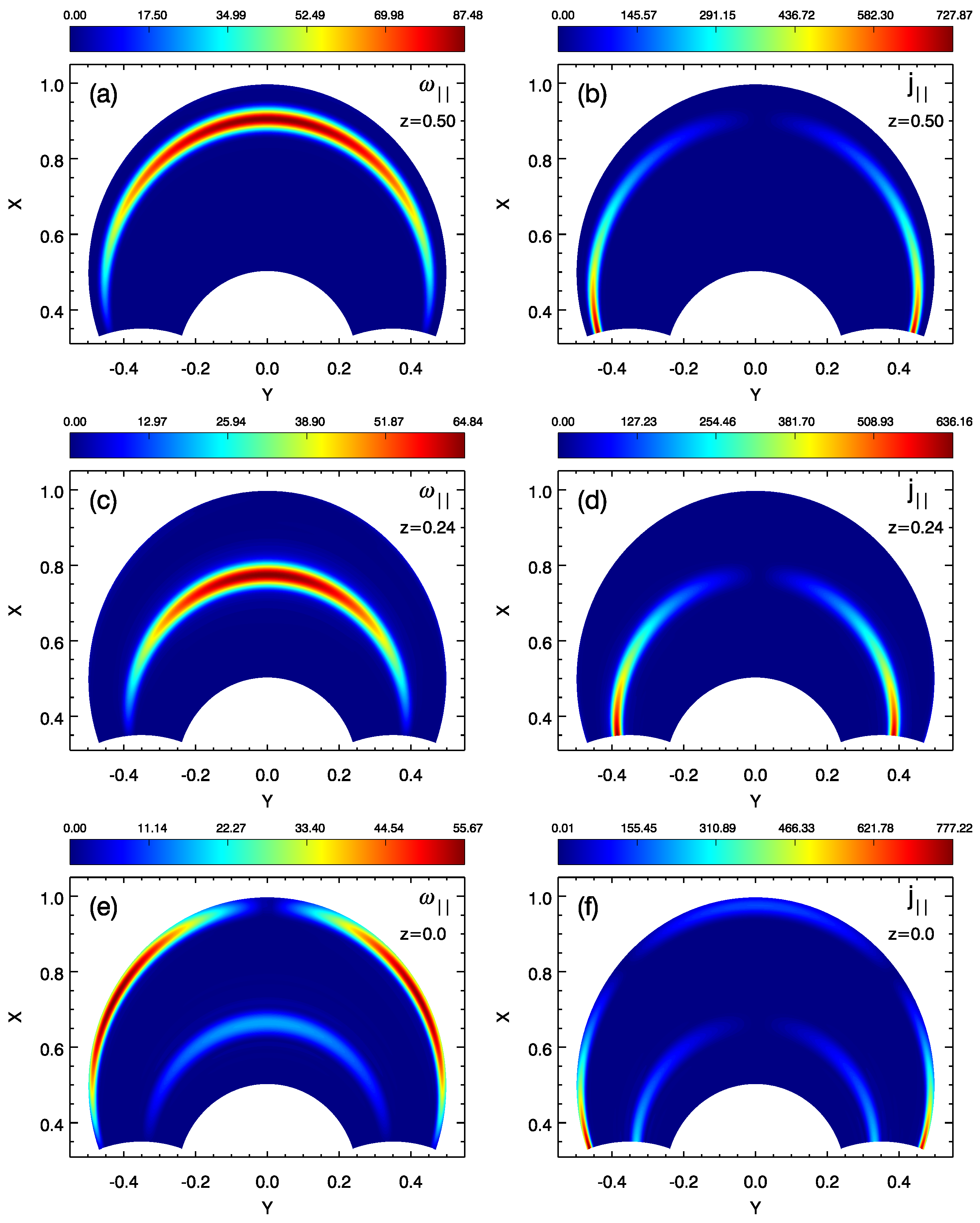
The Alfvén wave carries a field-aligned current, j , and field-aligned vorticity, ω , which are the γ components of the current and vorticity. These may be used to differentiate between the Alfvén and fast waves. Figure 2 shows the magnitude of these quantities once the complex normal mode has been formed. Figure 2a,c,e shows ω , and Figure 2b,d,f shows j . Figure 2a,b, Figure 2c,d, and Figure 2e,f correspond to three slices in planes of constant z taken at different locations along the length of the arcade (as indicated by the white lines in Figure 1c).
Figure 2a,b are taken from z = 0.5 , which is situated in the higher Alfvén speed part of the arcade. The resonant Alfvén wave (as indicated by parallel vorticity and current) clearly coincides with, and sits on, a field line towards the outer boundary of the arcade. The Alfvén wave is a fundamental mode in γ , having a node of vorticity at the photosphere and an antinode at the loop apex ( y = 0 ). As expected, this mode has a node of field-aligned current at the apex and antinodes at the photosphere. The equilibrium here is quasi 2D (approximately invariant in z), so one expects the Alfvén wave to be polarised with a plasma displacement in the z direction and to correspond to the toroidal Alfvén wave [8,9].
Figure 2c,d is taken from z = 0.24 , which is midway between the highest and lowest Alfvén speed regions. Here, the equilibrium varies most rapidly with z, so the properties of wave coupling in 3D should be most evident. The fundamental resonant Alfvén wave structure is still evident. The main difference is that the Alfvén wave has moved to shorter field lines where the magnetic field will be stronger. This seems reasonable as, given the lower Alfvén speed, the shorter field line and stronger magnetic field can have a natural frequency that matches the driving frequency.
Figure 2e,f is taken at the centre of the density enhancement where the Alfvén speed is lowest ( z = 0.0 ), and it is apparent that the trend has continued, with the fundamental Alfvén resonance moving to an even shorter field line than in Figure 2c,d. It is interesting to note that a new Alfvén resonance has been excited on the longer field lines. A careful examination of the current and vorticity shows this to be a second harmonic Alfvén wave (having a node of vorticity and antinode of current at the loop apex).
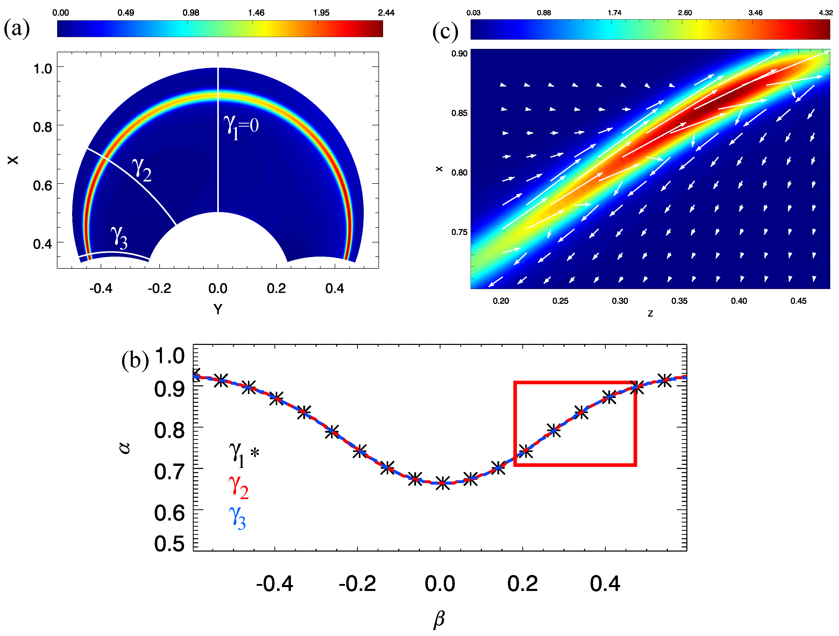
Some properties of the resonant Alfvén waves are easiest to see using the field-aligned coordinates α , β and γ . Figure 3a is a plot of the time-averaged energy density, W (see Equation (12) of Ref. [12]), in the plane z = β = 0.5 , which is also where the plots in Figure 2a,b were taken. Comparing Figure 3a and Figure 2a,b one can conclude that the time-averaged energy density is also a useful quantity for identifying the Alfvén wave. This is not surprising as the Alfvén wave, being resonant, has a much greater amplitude than the fast mode, so contributes far more to the total energy density.
The intersection with three coordinate surfaces of constant γ are also shown in Figure 3a. The surface γ = γ 1 = 0 corresponds to the y = 0 plane (the vertical plane that runs down the middle of the arcade). Suppose one moves along the γ = γ 1 line from α min to α max and determines where the energy density maximizes and let us call this value α W ( β = z = 0.5 , γ = γ 1 ) 0.922 . This is plotted as the point ( α , β ) = ( 0.922 , 0.5 ) in Figure 3b. One could then move along the arcade to a new value of β (or z) and repeat the process to generate α W ( β , γ = γ 1 ) . Figure 3b plots α = α W ( β , γ = γ 1 ) as the black symbols.
The same process can be repeated for the photospheric boundary at γ = γ 3 to find the function α W ( β , γ = γ 3 ) , which was used to generate the blue dashed line in Figure 3b. We could also consider an intermediate value γ = γ 2 , which is midway between the loop apex and the photosphere, and overplot α W ( β , γ = γ 2 ) as the red line in Figure 3b. The red and blue lines coincide to such a high degree that they appear as a single blue and red striped line. The α = α W ( β , γ = γ 1 ) result is plotted as symbols so as to not obscure the red and blue lines.
The striking result in Figure 3b is that all three lines coincide. This makes sense, since a resonant Alfvén wave is a property of the whole field line and extends along its entire length. Since α and β do not vary along a given field line, the same α and β values where the energy density maximizes will be found in the vertical plane ( γ = γ 1 ) and near the photospheric boundary ( γ = γ 3 ), or indeed at any intermediate γ surface. This also indicates that field-aligned coordinates are a far more natural coordinate system to study 3D resonant Alfvén waves than Cartesian or cylindrical coordinates.

3.2. Polarisation of Resonant Alfvén Waves

Recall that the resonant Alfvén wave in Figure 2a,b and Figure 3a is from z = 0.5 where the equilibrium is approximately invariant in z, so will be the familiar toroidal Alfvén wave with a plasma displacement in the toroidal (z) direction. It is not so obvious what the polarisation of the Alfvén wave in Figure 2c,d will be as the equilibrium here (at z = β = 0.24 ) is 3D. To address this point, consider the set of field lines in the vicinity of this region indicated by the red rectangle in Figure 3b. The intersection of these field lines with the y = 0 (equivalent to the γ = γ 1 = 0 surface) provides the domain shown in Figure 3c. Note that in this vertical plane h α and h β are both equal to unity, so α and β are equivalent to distance and coincide with the Cartesian coordinates x and z, which are used in Figure 3c. Figure 3c is a colour contour plot of the time-averaged energy density and the plasma velocity vectors at a time when their magnitude is a maximum. The plasma displacement is seen to be tangential to the path of the resonance, and this has also been shown to be true for the Alfvén wave magnetic field elsewhere on the field line [12].
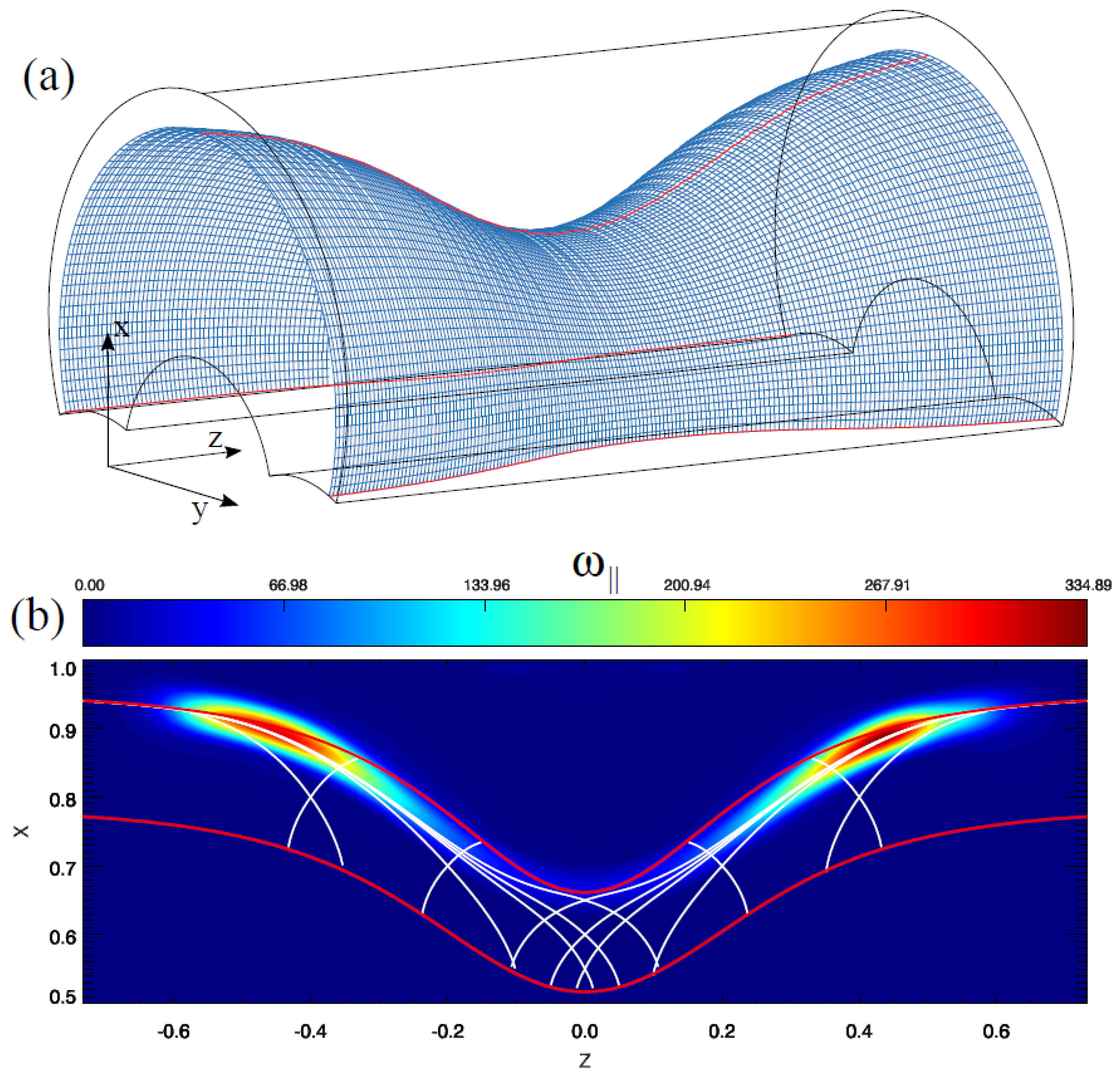
To help visualize the form of the resonant surface in 3D, let us begin by considering the lines α W ( β ) shown in Figure 3b. A pair of values for ( α , β ) identify a particular field line. If we run through the values ( α W ( β ) , β ) , the corresponding contiguous field lines will form the resonant surface, and is plotted in Figure 4a. The resonant Alfvén wave velocity and magnetic field perturbations will be perpendicular to the equilibrium field lines and also tangential to the resonant surface.

4. Discussion

It is known from studies in 2D equilibria [8,9] that the resonant Alfvén wave has a toroidal polarisation, and efficient coupling is found for low values of the wavenumber in the invariant direction. For high values of the wavenumber, the fast mode is evanescent and coupling is weak. However, decoupled Alfvén waves do exist in this limit and they have a poloidal polarisation [22]. As noted by Dungey [22] the natural frequencies of the toroidal and poloidal Alfvén waves are different, and in a dipole field the fundamental frequencies can differ by 30% [23]. The eigenvalue equations for these two waves were first derived in Ref. [22], although we restate these equations here in the field-aligned coordinate formalism [12,24]:
γ 1 h γ U α γ + 1 h γ γ ln h α h β U α γ + ω A 2 V 2 h γ U α = 0 ,
γ 1 h γ U β γ + 1 h γ γ ln h β h α U β γ + ω A 2 V 2 h γ U β = 0 .
In these equations, ω A is the Alfvén wave eigenfrequency, so corresponds to the poloidal frequency in Equation (12) and the toroidal frequency in Equation (13). The form of these equations is quite similar, and the key difference results from the middle term. If this term is zero, the toroidal and poloidal frequencies are identical. Such a situation will result if the ratio of h α to h β is independent of the field-aligned coordinate, γ . Geometrically, this corresponds to the cross-sectional shape of an elemental flux tube remaining constant along the length of the tube. This will be true for simple magnetic fields such as a uniform field or circular field lines around a line current. For more complex magnetic fields, such as a 2D or 3D dipole, this requirement is not met and the toroidal and poloidal frequencies will be different.
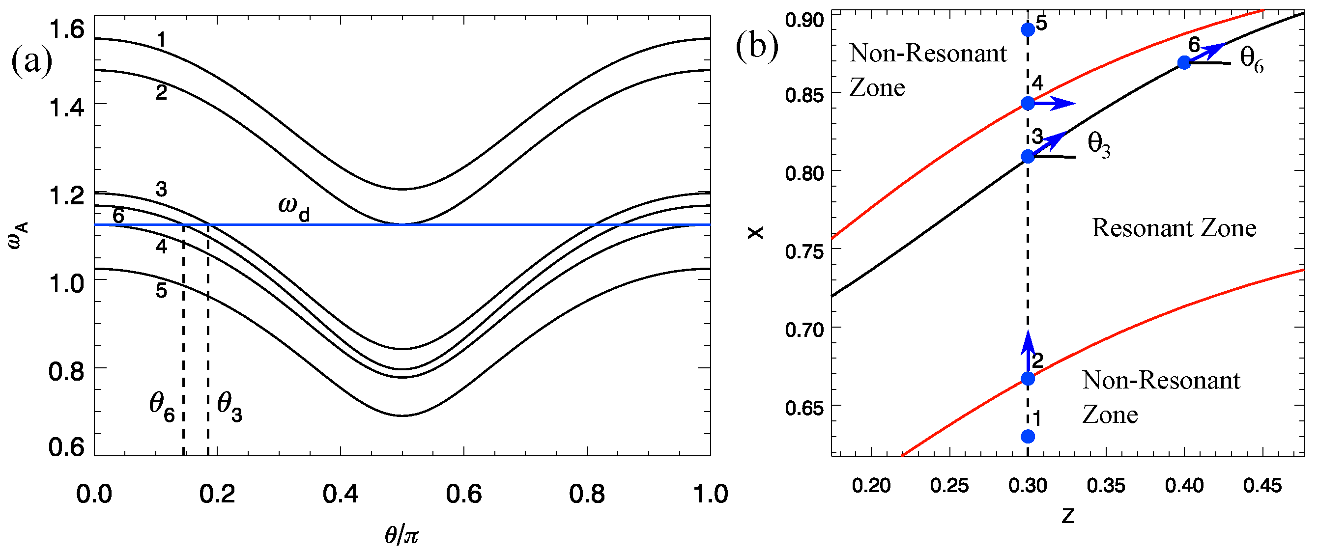
Until recently, the possibility of Alfvén waves with polarisation that is neither toroidal or poloidal had received little attention, yet Figure 3c evidently shows these waves are present. Motivated by simulations similar to those presented here, Ref. [12] showed how the toroidal and polidal equations given in Ref. [24] could be generalised to account for Alfvén waves of any polarisation, and this was used to generate Figure 5. Figure 5b shows a region of the vertical ( x , z ) plane similar to that in Figure 3c, and each blue dot is used to identify the intersection of a particular field line with the plane. For a given field line, the polarisation angle of the Alfvén wave is defined such that this angle is zero for the toroidal mode and π / 2 for the poloidal mode.
Consider the field line labelled 1 in Figure 5b. If one calculates the toroidal frequency of this field line, the value found can be plotted and corresponds to the θ = 0 point on the line labelled 1 in Figure 5a. Similarly, the poloidal frequency corresponds the point on this line for θ = π / 2 . Evidently, as the polarisation changes from toroidal to poloidal, there is a smooth and continuous change from one frequency to the other.
The ω A ( θ ) curves allow us to address the question of resonance and polarisation. Recall the simulation is driven at a frequency ω d = 1.125 , and this value is represented by the horizontal blue line in Figure 5a. For the field line labelled 1, it is not possible to choose a polarisation angle θ for which the Alfvén frequency matches ω d , so this field line is said to be non-resonant. As one moves along the vertical dashed line (in Figure 5b) to larger x, the Alfvén frequencies all decrease for this equilibrium. When field line 2 is reached, the minimum (poloidal) frequency matches ω d , so this field line can support a resonant poloidal Alfvén wave, and the direction of the plasma displacement is indicated by the blue arrow.
Proceeding to larger x, one arrives at field line 4, where the maximum (toroidal) frequency equals ω d . If the monotonic trend continues, field lines beyond this point (such as 5) will not be able to support a resonant Alfvén wave. Field lines between 2 and 4 can support a resonant Alfvén wave, and for field line 3 the required polarisation angle can be read from Figure 5a as θ 3 . When this process is repeated for different values of z, we arrive at the idea of a Resonant Zone and Non-Resonant Zones separated by Resonant Zone boundaries (shown as the red lines in Figure 5b). Figure 5b is termed a Resonance Map [12]. Similar diagrams have been used to study the evolution of highly asymmetric poloidal Alfvén waves [25,26,27].
All the field lines in the Resonant Zone have the potential to be resonant with ω d . However, Figure 2 and Figure 3c show that not all of these field lines are resonantly excited. Figure 3c shows a favoured ridge of Alfvén wave energy. Moreover, the path that the resonant ridge follows can be calculated by using the property that is seen in Figure 3c; namely, that the plasma velocity (which defines the polarisation angle) is directed along the ridge. Suppose field line 3 in Figure 5b lies on the resonant ridge. One can use Figure 5a to find the angle θ 3 that is required for the field line to be resonant, which provides the direction of the plasma displacement, and this is directed along the resonant ridge. One can step a short distance in this direction along the ridge to reach field line 6, and use the appropriate ω A ( θ ) curve in Figure 5a to determine the polarisation angle for this field line to be resonant—namely θ 6 . By repeating this process the solid black line in Figure 5b is produced, and this will coincide with the resonant Alfvén wave ridge.
Although we chose to start the above procedure by considering a field line on the resonant ridge, we could have started with any field line in the Resonant Zone, and produced a similar Resonant Path. Actually, there are infinitely many paths that can be produced, and why particular paths are favoured in a given simulation is still a matter of debate. Figure 4b shows the Resonance Map in the vertical ( x , z ) plane and uses the parallel vorticity to identify the resonant Alfvén wave ridge. The Resonant Zone boundaries are shown in Figure 4b as the red lines, and selected members of the family of Resonant Paths as white lines. There is a clear correspondence between where the Alfvén wave energy is located and certain Resonant Paths. Although there are still debates on how best to use Resonance Maps to interpret the properties of simulations, initial studies have shown the importance of paths coming from locations where the Resonant Paths are tangential to the Resonant Zone boundary [12,15].

5. Conclusions

This paper has presented numerical simulations of the resonant excitation of Alfvén waves by the fast mode in a 3D equilibrium. In a 2D equilibrium, it is always the toroidal Alfvén wave that is resonant, and it sits on a given toroidal surface. In 3D, the resonant Alfvén wave is no longer confined to being toroidal and is able to traverse toroidal surfaces. The permissible solutions can be identified using a Resonance Map. Figure 4a shows how including asymmetry in the medium along the length of the coronal arcade (i.e., a 3D medium) causes a variation in which field lines support resonant Alfvén waves, as well as the polarisation of these waves. This will be important for an accurate interpretation of coronal observations of resonant Alfvén waves; for a recent review, see [14].

Author Contributions

Conceptualization, A.W. and T.E.; methodology, A.W. and T.E.; software, A.W. and T.E.; validation, A.W. and T.E.; formal analysis, A.W. and T.E.; investigation, A.W. and T.E.; resources, A.W. and T.E.; data curation, T.E.; writing—original draft preparation, A.W.; writing—review and editing, A.W.; visualization, A.W. and T.E.; project administration, A.W. and T.E.; funding acquisition, A.W. and T.E. All authors have read and agreed to the published version of the manuscript.

Funding

The research of A.W. was funded in part by Science and Technology Facilities Council (STFC) grant ST/W001195/1 (UK). T.E. was funded in part by a Leverhulme Early Career Fellowship ECF-2019-155 (UK). This research was completed as part of the activities of an International Research Team funded by the International Space Science Institute, Bern, Switzerland.

Data Availability Statement

Data used to produce the simulation plots can be accessed at https://figshare.com/authors/Tom_Elsden/4743264 (accessed on 27 February 2023).

Conflicts of Interest

The authors declare no conflict of interest. The funders had no role in the design of the study; in the collection, analyses, or interpretation of data; in the writing of the manuscript; or in the decision to publish the results.

References

  1. Southwood, D.J. Some features of field line resonances in the magnetosphere. Planet. Space Sci. 1974, 22, 483–491. [Google Scholar] [CrossRef]
  2. Goossens, M.; Erdélyi, R.; Ruderman, M.S. Resonant MHD waves in the solar atmosphere. Space Sci. Rev. 2011, 158, 289–338. [Google Scholar] [CrossRef]
  3. Van Doorsselaere, T.; Srivastava, A.K.; Antolin, P.; Magyar, N.; Vasheghani Farahani, S.; Tian, H.; Kolotkov, D.; Ofman, L.; Guo, M.; Arregui, I.; et al. Coronal heating by MHD waves. Space Sci. Rev. 2020, 216, 140. [Google Scholar] [CrossRef]
  4. Allan, W.; White, S.P.; Poulter, E.M. Impulse-excited hydromagnetic cavity and field-line resonances in the magnetosphere. Planet. Space Sci. 1986, 34, 371–385. [Google Scholar] [CrossRef]
  5. Poedts, S.; Goossens, M.; Kerner, W. Numerical simulation of coronal heating by resonant absorption of Alfvén waves. Sol. Phys. 1989, 123, 83–115. [Google Scholar] [CrossRef]
  6. Goossens, M.; Ruderman, M.S.; Hollweg, J.V. Dissipative MHD solutions for resonant Alfvén waves in 1-dimensional magnetic flux tubes. Sol. Phys. 1995, 157, 75–102. [Google Scholar] [CrossRef]
  7. Wright, A.N.; Allan, W. Structure, phase motion, and heating within Alfvén resonances. J. Geophys. Res. Space Phys. 1996, 101, 17399–17408. [Google Scholar] [CrossRef]
  8. Wright, A.N.; Thompson, M.J. Analytical treatment of Alfvén resonances and singularities in nonuniform magnetoplasmas. Phys. Plasmas 1994, 1, 691–705. [Google Scholar] [CrossRef] [Green Version]
  9. Tirry, W.J.; Goossens, M. Dissipative MHD solutions for resonant Alfvén waves in two-dimensional poloidal magnetoplasmas. J. Geophys. Res. Space Phys. 1995, 100, 23687–23694. [Google Scholar] [CrossRef]
  10. Terradas, J.; Soler, R.; Luna, M.; Oliver, R.; Ballester, J.L.; Wright, A.N. Solar prominences embedded in flux ropes: Morphological features and dynamics from 3D MHD simulations. Astrophys. J. 2016, 820, 125. [Google Scholar] [CrossRef] [Green Version]
  11. Degeling, A.W.; Rankin, R.; Kabin, K.; Rae, I.J.; Fenrich, F.R. Modeling ULF waves in a compressed dipole magnetic field. J. Geophys. Res. Space Phys. 2010, 115, A10212. [Google Scholar] [CrossRef] [Green Version]
  12. Wright, A.N.; Elsden, T. The theoretical foundation of 3D Alfvén resonances: Normal modes. Astrophys. J. 2016, 833, 230. [Google Scholar] [CrossRef]
  13. Degeling, A.W.; Rae, I.J.; Watt, C.E.J.; Shi, Q.Q.; Rankin, R.; Zong, Q.G. Control of ULF wave accessibility to the inner magnetosphere by the convection of plasma density. J. Geophys. Res. Space Phys. 2018, 123, 1086–1099. [Google Scholar] [CrossRef] [Green Version]
  14. Elsden, T.; Wright, A.; Degeling, A. A review of the theory of 3-D Alfvén (field line) resonances. Front. Astron. Space Sci. 2022, 9, 917817. [Google Scholar] [CrossRef]
  15. Wright, A.; Degeling, A.W.; Elsden, T. Resonance maps for 3D Alfvén waves in a compressed dipole field. J. Geophys. Res. Space Phys. 2022, 127, e2022JA030294. [Google Scholar] [CrossRef]
  16. Wright, A.N.; Elsden, T. Simulations of MHD wave propagation and coupling in a 3-D magnetosphere. J. Geophys. Res. Space Phys. 2020, 125, e27589. [Google Scholar] [CrossRef]
  17. Halberstadt, G.; Goedbloed, J.P. The continuous Alfvén spectrum of line-tied coronal loops. Astron. Astrophys. 1993, 280, 647–660. Available online: https://ui.adsabs.harvard.edu/abs/1993A%26A...280..647H (accessed on 27 February 2023).
  18. Prokopyszyn, A.P.K.; Wright, A.N.; Hood, A.W. Line-tied boundary conditions can cause resonant absorption models to generate unphysically large boundary layers. Astrophys. J. 2021, 914, 15. [Google Scholar] [CrossRef]
  19. Elsden, T.; Wright, A.N. The theoretical foundation of 3-D Alfvén resonances: Time-dependent solutions. J. Geophys. Res. Space Phys. 2017, 122, 3247–3261. [Google Scholar] [CrossRef] [Green Version]
  20. Elsden, T.; Wright, A.N. The Broadband excitation of 3-D Alfvén resonances in a MHD waveguide. J. Geophys. Res. Space Phys. 2018, 123, 530–547. [Google Scholar] [CrossRef] [Green Version]
  21. Elsden, T.; Wright, A.N. The effect of fast normal mode structure and magnetopause forcing on FLRs in a 3-D waveguide. J. Geophys. Res. Space Phys. 2019, 124, 178–196. [Google Scholar] [CrossRef] [Green Version]
  22. Dungey, J.W. Electrodynamics of the Outer Atmosphere: Report to National Science Foundation on Work Carried on under Grant NSF-G450; Pennsylvania State University, Ionosphere Research Laboratory: State College, PA, USA, 1954. [Google Scholar]
  23. Elsden, T. Numerical Modelling of Ultra Low Frequency Waves in Earth’s Magnetosphere. Ph.D. Thesis, University of St Andrews, St. Andrews, UK, 2016. [Google Scholar] [CrossRef] [Green Version]
  24. Singer, H.J.; Southwood, D.J.; Walker, R.J.; Kivelson, M.G. Alfvén wave resonances in a realistic magnetospheric magnetic field geometry. J. Geophys. Res. Space Phys. 1981, 86, 4589–4596. [Google Scholar] [CrossRef] [Green Version]
  25. Leonovich, A.S.; Mazur, V.A. A theory of transverse small-scale standing Alfvén waves in an axially symmetric magnetosphere. Planet. Space Sci. 1993, 41, 697–717. [Google Scholar] [CrossRef]
  26. Klimushkin, D.Y.; Leonovich, A.S.; Mazur, V.A. On the propagation of transversally small-scale standing Alfvén waves in a three-dimensionally inhomogeneous magnetosphere. J. Geophys. Res. Space Phys. 1995, 100, 9527–9534. [Google Scholar] [CrossRef]
  27. Elsden, T.; Wright, A.N. Evolution of high-m poloidal Alfvén waves in a dipole magnetic field. J. Geophys. Res. Space Phys. 2020, 125, e28187. [Google Scholar] [CrossRef]
Figure 1. A sketch of the model field geometry. (a) A 3D (three-dimensional) view of the arcade based on a line dipole aligned with the z axis and sitting below the photosphere. The blue lines represent the portion of the magnetic field lines above the photosphere. (b) A cross-sectional view of the simulation domain and its boundaries in terms of field-aligned coordinates, α and γ (1). (c) The variation of Alfvén speed (V) in the vertical ( x , z ) plane (also the γ = 0 plane) that runs the length of the arcade. The vertical white lines indicate the z positions used to study the Alfvén wave fields displayed in Figure 2.
Physics 05 00023 g001
Figure 2. Magnitude of the normal mode’s field aligned vorticity, | ω | (a,c,e), and current, | j | (b,d,f) at z = 0.5 (a,b), 0.24 (c,d), and 0.0 (e,f).
Physics 05 00023 g002
Figure 3. (a) Time-averaged energy density in the plane β = z = 0.5 . The intersection with three surfaces of the field-aligned coordinate ( γ 1 = 0 , γ = γ 2 and γ = γ 3 ) are also shown. (b) The location of where the energy density maximizes α W ( β , γ ) for the three surfaces γ = γ 1 (black symbols), γ 2 (red line) and γ 3 (blue dashed line). (c) A close-up view of the energy density on the field lines carrying a 3D Alfvén resonance (identified by the red rectangle in (b)) plotted in the γ = γ 1 = 0 plane (equivalent to the y = 0 plane) with velocity vectors overplotted. See text for details.
Physics 05 00023 g003
Figure 4. (a) The surface containing the resonant Alfvén waves (identified from Figure 3b as a maximum of the time-averaged energy density). (b) A cut in the vertical y = 0 plane of the magnitude of the field-aligned vorticity. Overplotted is the Resonance Map showing permissible Resonant Paths (white lines) and the boundaries of the Resonant Zone (red lines). See text for details.
Physics 05 00023 g004
Figure 5. (a) The variation of natural Alfvén frequency, ω A , with polarisation angle, θ , for six different field lines, labelled 1–6. The horizontal blue line denotes the driving frequency, ω d . (b) The intersections of these field lines with the vertical ( x , z ) plane that runs the length of the arcade are shown as blue dots. The blue arrows indicate the polarisation required for the ω A to equal ω d , i.e., the resonance condition. The solid black line represents a permissible Resonant Path, and the red lines indicate the boundaries of the Resonant Zone.
Physics 05 00023 g005
Disclaimer/Publisher’s Note: The statements, opinions and data contained in all publications are solely those of the individual author(s) and contributor(s) and not of MDPI and/or the editor(s). MDPI and/or the editor(s) disclaim responsibility for any injury to people or property resulting from any ideas, methods, instructions or products referred to in the content.