
Article

Nanoporous Carbon Catalysts in Fischer–Tropsch Synthesis

by
Cristian Toncón-Leal
1,
Kiara Montiel-Centeno
1,2,
Deicy Barrera
1,
Carlos Páez-González
3,
Sebastián Amaya-Roncancio
4,
Jhonny Villarroel-Rocha
1,
Leticia Romero-Castro
1 and
Karim Sapag
1,*
1
Laboratorio de Sólidos Porosos (LabSoP), Instituto de Física Aplicada (INFAP)–Consejo Nacional de Investigaciones Científicas y Técnicas (CONICET), Universidad Nacional de San Luis, Av. Ejército de los Andes 950, San Luis 5700, Argentina
2
Department Hydrogen and Power to X, Iberian Centre for Research in Energy Storage (CIIAE), 10003 Cáceres, Spain
3
Escuela de Física, Universidad Industrial de Santander, Bucaramanga 680002, Colombia
4
Grupo de Simulación de Materiales, Escuela de Física, Universidad Pedagógica y Tecnológica de Colombia, Avenida Central del Norte 39-115, Tunja 150003, Colombia
*
Author to whom correspondence should be addressed.
Reactions 2026, 7(2), 35; https://doi.org/10.3390/reactions7020035
Submission received: 5 February 2026 / Revised: 13 May 2026 / Accepted: 23 May 2026 / Published: 31 May 2026
(This article belongs to the Special Issue Fischer-Tropsch Synthesis: Bridging Carbon Sustainability)

Abstract

Ordered mesoporous carbons have emerged as versatile supports for Fischer–Tropsch catalysts due to their high surface area, tunable pore architectures, and chemical stability. However, the influence of active-metal identity on product selectivity within a common carbon framework remains insufficiently understood, particularly when Fe and Co are compared under rigorously identical conditions. To address this aspect, we prepared Fe- and Co-based catalysts with comparable nominal metal loadings supported on CMK-5 carbon material and evaluated their structural, surface, and catalytic properties. Comprehensive characterization revealed distinct metal-dependent behaviors, and catalytic testing between 423 and 598 K at 2 MPa showed that the catalyst CMK-5(Co10) exhibited substantially higher activity, whereas CMK-5(Fe10) provided a more stable product distribution and exclusively paraffinic C2–C3 products across the studied temperature range. In contrast, CMK-5(Co10) displayed a pronounced temperature-dependent selectivity, with increasing methane formation and the emergence of olefinic C2–C3 species at intermediate and high temperatures. Chain-growth probabilities were consistent with these trends. Complementary Density Functional Theory and Kinetic Monte Carlo analyses indicated stronger binding of carbonaceous intermediates on Fe clusters and more accessible C–C coupling pathways on Co clusters. Together, these results clarify how active-metal identity governs selectivity within a shared CMK-5 architecture and provide guidelines for designing carbon-supported Fischer–Tropsch catalysts with controlled product distributions.

1. Introduction

Fischer–Tropsch synthesis (FTS) remains one of the most relevant catalytic routes for converting synthesis gas (CO + H2) into hydrocarbons and oxygenated products, and it continues to attract renewed interest as a platform for producing fuels and chemicals from alternative carbon resources, including biomass-derived syngas and CO2-containing feedstocks [1]. Because FTS can produce a wide spectrum of products, ranging from methane to long-chain hydrocarbons and oxygenates, controlling product distribution remains a central challenge in catalyst design [2]. In this context, catalytic performance is governed not only by the nature of the active metal but also by the physicochemical properties of the support and the resulting metal–support interactions [3].
Among the most widely studied FTS catalysts, iron- and cobalt-based systems exhibit markedly different catalytic behaviors. Cobalt catalysts are generally associated with high intrinsic activity, low water–gas shift activity, and a stronger tendency toward paraffinic hydrocarbons under conventional low-temperature FTS conditions [4]. In contrast, iron catalysts display more complex selectivity patterns because they can involve oxides, carbides, and metallic states while simultaneously catalyzing both Fischer–Tropsch synthesis and the water–gas shift reaction [3]. As a result, methane selectivity, chain-growth behavior, and paraffin/olefin distribution remain highly sensitive to both catalyst formulation and the identity of the active metal [2,3,4].
Support effects are particularly relevant in this context. Mesostructured oxides and silicas, such as SBA-15, a well-known ordered mesoporous silica material and related materials, have been extensively investigated for their high surface area, ordered pore systems, and thermal stability [5]. In these catalysts, the support often determines metal anchoring, particle dispersion, and the strength of metal–support interactions, which in turn influence the evolution of the active phase and the final activity-selectivity relationship under Fischer–Tropsch conditions. This behavior has been particularly documented for cobalt catalysts on oxide supports, where support chemistry and pore structure strongly affect reducibility and catalytic performance [6].
However, the current state of the art also shows that carbon materials should not be treated merely as passive alternatives to oxide supports. Recent reviews on carbon-supported FTS catalysts indicate that carbonaceous matrices can influence hydrogen transfer phenomena, surface hydrophobicity, accessibility of metal sites, and secondary hydrogenation pathways, thereby affecting methane formation, chain growth, and paraffin/olefin selectivity [7,8]. In addition, the cobalt-on-carbon literature shows that variations in carbon structure and porosity directly affect cobalt dispersion, turnover behavior, and the hydrocarbon product spectrum, confirming that support effects on carbon materials are not secondary but intrinsic to catalyst performance [9,10].
Within the broader family of carbon-supported Fischer–Tropsch catalysts, ordered mesoporous carbons (OMCs), particularly CMK-type materials, are especially attractive because they combine high specific surface area, uniform mesoporosity, and comparatively weaker interfacial interactions than many conventional oxides [7,8]. However, the available OMC literature remains primarily focused on CMK-3 and related architectures, while the role of CMK-5 in Fischer–Tropsch synthesis remains less clearly defined [7,9]. For iron catalysts, CMK-3- and OMC-based systems have been associated with low methane formation, high lower-olefin productivity, and a marked sensitivity to activation procedure and support functionalization [11,12,13]. For cobalt catalysts, studies on ordered mesoporous carbons have shown that carbon precursor amount, pretreatment conditions, nitrogen doping, and graphitization degree strongly affect cobalt dispersion, reducibility, and the balance between activity and C5+ selectivity [14,15]. In addition, confinement effects within ordered mesoporous carbon architectures have been shown to modify catalytic performance under Fischer–Tropsch conditions substantially [16,17]. Taken together, these reports indicate that OMC-supported Fe and Co catalysts are highly sensitive to the architecture and surface chemistry of the carbon matrix, yet direct comparisons between the two active metals on the same ordered mesoporous carbon support remain scarce. Consequently, the specific role of CMK-5 in modulating reducibility, confinement, chain growth, and the paraffin/olefin balance remains poorly established, making systematic comparisons within a common CMK-5 framework particularly relevant for clarifying metal-dependent versus support-driven effects.
In parallel, atomistic modeling has become a valuable tool for interpreting catalytic trends in FTS. Density functional theory (DFT) provides access to adsorption energies and elementary reaction steps [18]. At the same time, kinetic Monte Carlo (KMC) simulations connect those energetic parameters to the evolution of surface species and product selectivity [19]. However, combined experimental–theoretical studies specifically addressing Fe- and Co-based catalysts supported on ordered mesoporous carbons remain limited, particularly regarding temperature-dependent selectivity trends and the paraffin/olefin balance [20].
In this work, CMK-5 was used as an ordered mesoporous carbon support to prepare Fe- and Co-based catalysts with comparable nominal metal loading, enabling a direct comparison of their catalytic behavior under identical Fischer–Tropsch conditions (H2/CO 2:1 ratio) over a broad temperature range (423–598 K at 2 MPa). The materials were comprehensively characterized to assess their textural properties, metal incorporation, dispersion, and reducibility. In parallel, DFT calculations and KMC simulations were employed as a qualitative mechanistic framework to analyze adsorption trends, hydrogenation pathways, and C–C coupling on Fe13 and Co13 clusters. By combining catalytic results, structural characterization, and theoretical analysis, this study aims to clarify how the identity of the active metal influences methane formation, paraffin/olefin distribution, and chain-growth behavior in CMK-5-supported Fischer–Tropsch catalysts.
Thus, the novelty of the present work lies not merely in combining experiments and modeling, but also in addressing a specific gap in the current literature by directly comparing Fe- and Co-based catalysts supported on the same CMK-5 architecture under identical reaction conditions. This strategy allows for a clearer disentangling of the respective contributions of metal identity and the ordered mesoporous carbon support to temperature-dependent selectivity trends, providing new insights into methane formation, the paraffin/olefin balance, and chain-growth behavior in Fischer–Tropsch synthesis.

2. Materials and Methods

2.1. Synthesis of CMK-5

The mesoporous carbon CMK-5 was synthesized using SBA-15 silica as an inorganic template, previously prepared according to the method described by Montiel-Centeno et al. (2019) [21]. SBA-15 was used solely as a sacrificial material for synthesis and not as a catalytic support. For the nanocasting procedure, furfuryl alcohol (FA, C5H6O2, 98%) was employed as the carbon precursor, oxalic acid (OA, C2H2O4, 99.5%) as the polymerization catalyst, and 1,3,5-trimethylbenzene (TMB, C9H12, 98%) as the solvent. The quantities used were 1.0 g of SBA-15, 2.1 g of FA, 3.9 g of TMB, and 0.016 g of OA. Initially, FA was completely dissolved in TMB, followed by the addition of OA. The resulting solution was stirred at room temperature for 30 min to ensure thorough mixing of the reagents. Subsequently, this solution was slowly impregnated onto the silica template using the incipient-wetness method at room temperature. The impregnated mixture was stirred in a rotary evaporator at 308 K for 2 h to promote uniform distribution of the precursor within the SBA-15 pores. Polymerization of FA was carried out by heating the mixture to 333 K for 16 h, followed by an additional 16 h at 353 K. After polymerization, the material was carbonized under a N2 atmosphere with a constant flow of 180 mL·min−1. The heating program was as follows: from room temperature to 423 K at 1 K·min−1 over 3 h, then to 573 K at the same rate, and finally to 1173 K at 3 K·min−1, maintaining this final temperature for 4 h. Finally, the silica template was removed by treatment with 5% hydrofluoric acid, keeping the material under stirring at room temperature for 24 h. The resulting CMK-5 was thoroughly washed with a 50:50 (v/v) water: ethanol mixture until the conductivity dropped below 10 µS·cm−1, then dried at 353 K for 12 h.

2.2. Incorporation of the Active Phase

The incipient-wetness impregnation method was employed, using absolute ethanol (Merck, 99.8%) as the solvent for iron(III) nitrate (Fe(NO3)3·9H2O, Anedra, 98.0%) or cobalt(II) nitrate (Co(NO3)2·6H2O, Biopack, 98.0%). The metal solution was added gradually to the support, and the solvent was subsequently removed under reduced pressure using a rotary evaporator (Decalab Fbr, Ciudad Autónoma de Buenos Aires (CABA), Argentina). This procedure was carried out under continuous stirring, with vacuum and ultrasonication, maintaining a temperature of 318 K for 1 h. The resulting samples were then heated to 573 K for 10 h in a muffle furnace under N2 atmosphere. In all cases, the amount of iron(III) or cobalt(II) nitrate employed was calculated to achieve a final metal loading of 10% wt in the material.

2.3. Catalysts Characterization

The N2 adsorption–desorption isotherms at 77 K were recorded using a ASAP 2000 analyzer (Micromeritics Instrument Corporation, Norcross, GA, USA). Before the measurements, the samples were degassed at 523 K for 12 h to remove adsorbed species. From the experimental data, the textural parameters were determined, including the specific surface area (SBET), micropore volume (VμP), primary mesopore volume (VPM), total pore volume (VTP), and pore size distribution (PSD). The SBET and VTP values were obtained by applying the Brunauer, Emmett and Teller (BET) method and the Gurvich rule, respectively, while VPM and VμP were derived from the αS-plot approach. The PSD of CMK-5 samples was evaluated using the Quenched solid density functional theory (QSDFT) model for N2 adsorption on Carbon with slit- or cylindrical-shaped pores.
The metal content of the catalysts was determined by X-ray fluorescence (XRF) using a Bruker S2 Ranger spectrometer (Bruker AXS GmbH, Germany) equipped with Pd or Ag radiation. The instrument operates with a maximum power of 50 W, a maximum voltage of 50 kV, and a maximum current of 2 mA, and is fitted with a silicon drift detector (XFlash®) from the same manufacturer.
XRD patterns of the calcined samples were recorded using an Empyrean diffractometer (PANalytical B.V., The Netherlands) equipped with Cu Kα radiation (λ = 0.1542 nm), operating at 40 kV and 45 mA. The measurements were carried out at a scan rate of 1° min−1 over the 2θ range of 5–80°.
Scanning electron microscopy (SEM) images were acquired using a LEO 1450 VP SEM (Carl Zeiss SMT Ltd., UK) equipped with an energy-dispersive X-ray spectroscopy (EDS) detector Genesis 2000 (EDAX Inc., Mahwah, NJ, USA). Before analysis, the samples were coated with a ~30 nm gold layer and mounted on an aluminum sample holder using carbon tape. The images were recorded at an accelerating voltage of 15 kV.
Transmission electron microscopy (TEM) analyses were performed on a Tecnai G2 F20 microscope (FEI Company, Hillsboro, OR, USA) operated at 200 kV, with the samples maintained at room temperature. TEM specimens were prepared by dispersing the powders in ethanol without sonication to preserve their structural integrity and by depositing a drop of the suspension onto a lacey carbon-coated copper grid. Elemental mapping was carried out using a Quantum ER spectrometer (EDAX Inc., Mahwah, NJ, USA) attached to the microscope.
X-ray photoelectron spectroscopy (XPS) analyses were performed in a VG Microtech ESCA ultra-high-vacuum chamber (VG Scientific Ltd., East Grinstead, UK) equipped with an Al anode (Al Kα radiation) and a VG100AX hemispherical analyzer from the same manufacturer. The spectra were corrected for charging effects by referencing the Si 2p binding energy at 103.4 eV.
Temperature-programmed reduction (TPR) experiments were carried out on a Chembet 3000 analyzer (Quantachrome Instruments, Boynton Beach, FL, USA) using a H2/N2 mixture containing 10% H2 at a flow rate of 30 cm3·s−1. Before the measurements, the samples were degassed at 373 K for 2 h. Subsequently, the temperature was increased from 373 K to 1173 K at a heating rate of 10 K·min−1. The H2 consumption of the catalysts was quantified using a calibration curve prepared with copper(II) oxide (Aldrich Chemical Co., Milwaukee, WI, USA 99.995%) as an external standard.

2.4. Fischer–Tropsch Synthesis Conditions

Catalytic performance was evaluated in a fixed-bed reactor (Microactivity Reference, PID Eng&Tech, Spain). Approximately 60–70 mg of supported catalysts, with particle sizes in the range of 0.300–0.425 mm, were diluted with silicon carbide at a 1:8 catalyst/SiC mass ratio, and with (Weight Hourly Space Velocity) WHSV = 8100 mL·g−1·h−1. Reactions were conducted at 2 MPa with an H2/CO feed ratio of 2, and performance was evaluated over 423–598 K. Before testing, the materials were reduced in situ under a hydrogen flow at atmospheric pressure and 703 K for 6 h. After reduction, the reactor was cooled to the desired reaction temperature. Reaction products were analyzed online (C1–C9) using a Clarus 500 gas chromatograph (PerkinElmer Inc., Waltham, MA, USA) equipped with a thermal conductivity (TCD) and a flame ionization (FID) detectors from same manufacturer, while a trap maintained at 353 K and 2 MPa was employed to collect and quantify waxes offline (C10+); in both experimental setups, helium served as the carrier gas [22].
The hydrocarbon product distribution in FTS can be described by the Anderson-Schulz-Flory (ASF) model [23], which relates the distribution of hydrocarbons to the chain growth probability (α). In terms of carbon selectivity, the ASF distribution is given by:
S n = n ( 1 α ) 2 α n 1
where S n represents the carbon selectivity of hydrocarbons containing n carbon atoms.
In principle, α can be determined from the experimental product distribution using individual carbon numbers. However, in the present work, the products were quantified in grouped fractions (C1, C2–C4, C5–C9, and C10+), which prevents constructing a conventional ASF distribution plot. Therefore, the chain growth probability was approximately estimated from the fraction of heavier hydrocarbons (C5+). The C5+ selectivity was obtained as the sum of the C5–C9 and C10+ fractions. According to the ASF distribution, the fraction of hydrocarbons with carbon numbers n 5 can be expressed as S C 5 + = α 4 ( 5 4 α ) , from which α was calculated by numerically solving the equation using the experimental S C 5 + values. It should be noted that this approach provides an estimate of the chain-growth probability.

2.5. Density Functional Theory (DFT)

The adsorption and binding energies for the different metal clusters were calculated using density functional theory within the Quantum Espresso package. The electron–ion interaction was described by ultrasoft pseudopotentials generated by the Rappe–Rabe–Kaxiras–Joannopoulos method [24]. The generalized gradient approximation (GGA) was used with the Perdew–Burke–Ernzerhof (PBE) exchange-correlation density functional [25]. When the van der Waals interactions were considered, the DFT-D3 semiempirical method was employed [26]. The cutoff energy was set to 60 Ry for all atoms involved. The threshold for self-consistency was 1 × 10⁻⁶ Ry. Brillouin zone integration was defined at the gamma point within a box with a 20 Å edge vacuum region. For the relaxation calculations, the quasi-Newton Broyden–Fletcher–Goldfarb–Shanno algorithm was employed until the forces on each atom were less than 10−3 eV·Å−1, and the energy difference between consecutive steps was less than 10−6 eV. In all the metal clusters employed, all the atoms were free to relax. The minimum energy paths for CH4 and C2H4 formation were calculated using the CI-NEB [27]. Here, the local minima were found through the conjugate gradient technique with a threshold path of 0.1 eV·Å−1. Finally, the optimization step was set to five images per calculation, with the first and last images fixed. All molecular and density plots were made with the VESTA and Xcrysden packages [28,29]. The binding energy or adsorption energy (Eint) of the adsorbate CHn (n = 0–4) and C2H4 was calculated using the equation,
E i n t = E m o l - M 13 E M 13 E m o l
where Emol-M13 is the total energy of the systems CH4, CH3, CH2, CH, or C adsorbed on the M13 cluster after geometric optimization, EM13 is the energy of the 13-atom metal cluster, and Emol is the total energy of the isolated molecule [30]. More explanation of these methods can be found in [31].

2.6. Kinetic Monte Carlo (KMC)

The methods for implementing Kinetic Monte Carlo simulations on Fe13 and Co13 are described in detail in [32]. In the present work, the reaction mechanisms considered were:
C H 4 ( g ) +     C H 4 *
C H 4 * +   C H 3 * + H *
C H 3 * +   C H 2 * + H *
C H 2 * +   C H * + H *
C H * +   C * + H *
C H 2 * + C H 2 * C 2 H 4 *
Here, the * denotes an adsorbed species to an adsorption site on the metal cluster. The increase in time after reaction execution is determined by t = l n ( ρ ) K , where ρ is a random number between (0, 1), and K is the sum of all the possible events calculated from Equations (3) and (8) [32]. It must be noted that the value of time “t” in our KMC simulations is computationally intensive and time-consuming as the simulation temperature increases. To avoid this, all the systems studied were simulated at a specific temperature for 1 × 10⁶ reactions, and the coverage values of all the surface species were calculated and averaged 1 × 10³ times; the algorithm presented elsewhere [31] was repeated and averaged 1 × 10³ times. In the same line, the desorption of H2 molecules from the surface was accounted for and averaged over 1 × 10³ reactions. The temperature range was from 600 K to 1200 K, with a 50 K increment calculated independently.

3. Results and Discussion

3.1. Materials Characterization

The N2 adsorption–desorption isotherms at 77 K for pristine CMK-5 and the metal-impregnated samples are shown in Figure 1a. All materials exhibit Type IV isotherms according to the IUPAC classification, with H2-Type hysteresis loops, indicating the presence of mesoporosity in their structures. The pronounced capillary condensation step and the narrow hysteresis loop are consistent with the ordered mesostructure replicated from SBA-15 [21]. Pristine CMK-5 shows high N2 uptake across the entire relative pressure range, reflecting its substantial porosity. A sharp increase in adsorption at low relative pressures (p/p0 < 0.1) indicates the presence of microporosity, while the pronounced capillary condensation step at intermediate pressures confirms the predominance of mesopores. After impregnation with Fe and Co (nominal 10% wt), the total adsorption capacity decreases significantly, indicating partial pore filling by metal oxide nanoparticles [20]. The reduction in adsorbed volume is more pronounced for CMK-5(Co10), suggesting a higher degree of pore occupation or stronger interactions between cobalt species and the carbon matrix.
The textural parameters derived from the N2 adsorption–desorption isotherms at 77 K are summarized in Table 1. Pristine CMK-5 exhibits a high specific surface area (SBET = 1220 m2·g−1) and total pore volume (VTP) of 0.93 cm3·g−1, with a significant contribution from mesoporosity (VPM = 0.62 cm3·g−1) and a measurable micropore volume (VµP = 0.13 cm3·g−1). These values confirm the successful replication of the mesoporous silica template and the development of additional microporosity within the carbon walls. Metal incorporation leads to a systematic decrease in all textural parameters. For CMK-5(Fe10), SBET decreases to 930 m2·g−1 and VTP to 0.95 cm3·g−1, whereas CMK-5(Co10) exhibits a more pronounced reduction (SBET = 620 m2·g−1; VTP = 0.63 cm3·g−1). Additionally, the experimental metal loadings were close to the nominal values, confirming the efficiency of the impregnation procedure.
The pore size distributions (Figure 1b) show that pristine CMK-5 has a trimodal distribution: a microporous contribution at approximately 1.0 nm and two mesoporous contributions centered around 3.5 nm and 4.5 nm. The 4.5 nm population corresponds to intertubular porosity, while a shoulder at 3.4 nm is associated with intratubular mesoporosity. These populations reflect a well-defined mesostructural order, characteristic of the replicated channels in CMK-5. After impregnation with metal oxides, a decrease in pore volume is observed across all three regions, indicating partial filling of micropores, intratubular, and intertubular mesopores, with the most pronounced reduction occurring in the intertubular mesoporosity and for the cobalt-containing catalyst. Moreover, a slight broadening of the intertubular mesopore distribution is observed, suggesting that the incorporation of metal nanoparticles partially expands the porous framework [33].
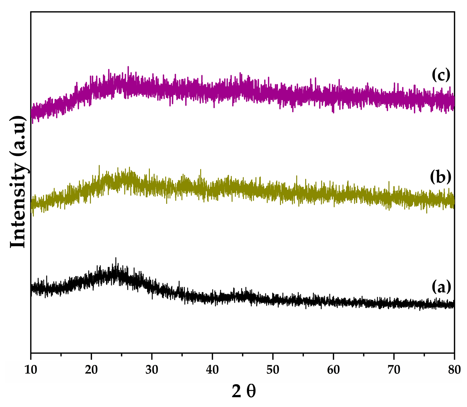
The X-ray diffraction patterns of the materials are shown in Figure 2. In all cases, a pattern characterized by a broad band centered approximately between 2θ = 20–30° is observed, which is attributed to the predominantly amorphous nature of the CMK-5 carbon support. For the iron- and cobalt-impregnated materials, no characteristic reflections corresponding to crystalline metal oxide phases are detected. The absence of well-defined diffraction peaks may be attributed to several factors: (i) the small particle size of the metallic species, which may be below the detection limit of the technique; (ii) a high dispersion of the metallic species on the support surface; and (iii) possible fluorescence effects associated with the elements present in the samples [34]. These results suggest that the metallic species are highly dispersed on the CMK-5 support or present as nanometric domains with low crystallinity.
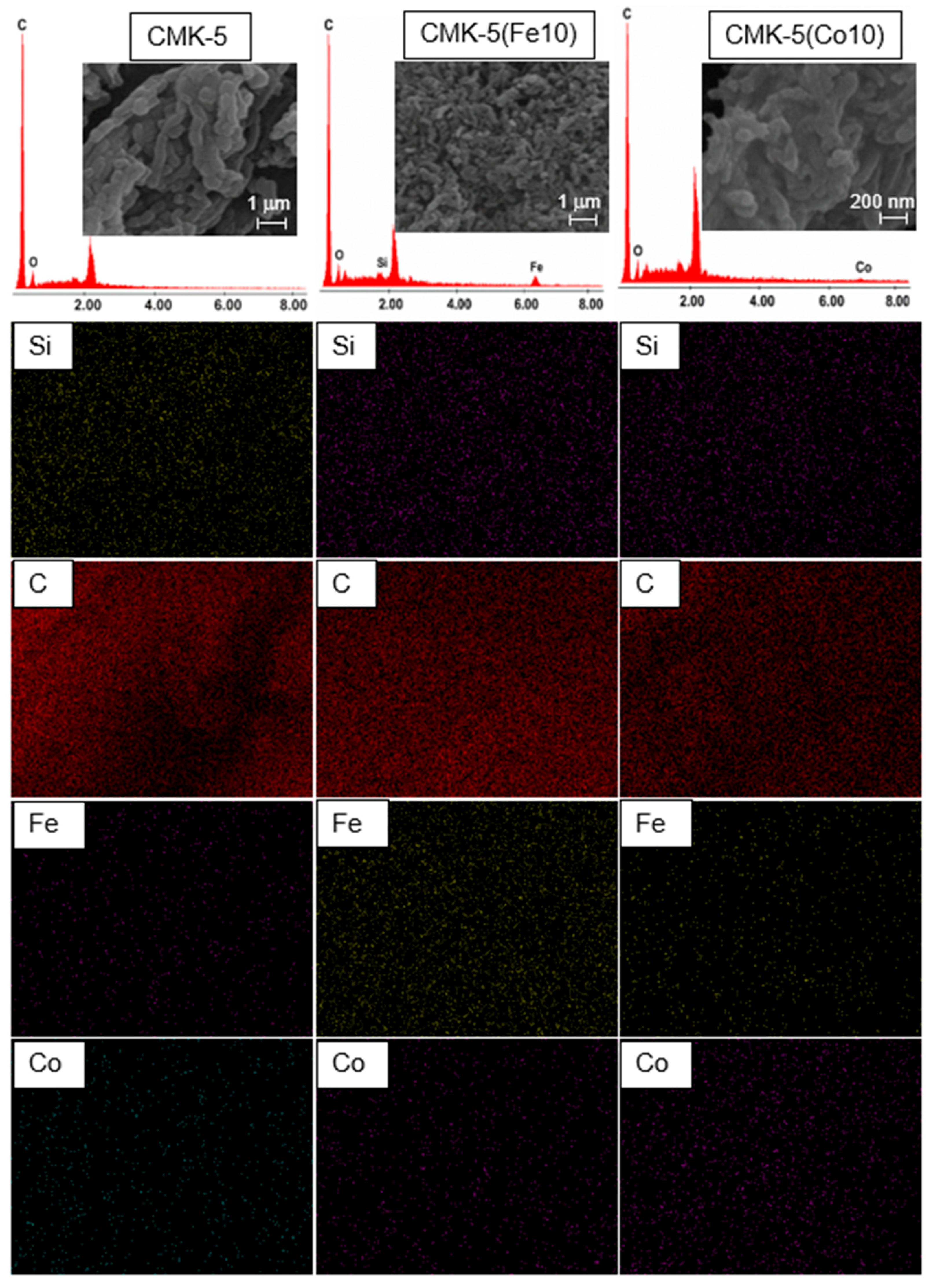
In Figure 3, SEM images, Energy dispersive X-ray (EDX) spectra, and elemental (EDS) maps of the CMK-5 support and the materials impregnated with the Fe or Co active phase are presented. In all samples, the signal corresponding to the support elements (Si and C) is predominantly observed. The presence of Si in the carbon-based materials is attributed to residual impurities from the template used during CMK-5 synthesis. For the impregnated materials, no regions with preferential accumulation of cobalt or iron are detected, indicating a homogeneous distribution of the metal species on the support. As expected, the iron-containing catalyst exhibits a higher Fe signal. In contrast, the cobalt-containing catalyst shows a higher Co signal in the corresponding EDX spectra and elemental maps, confirming the successful incorporation of the respective active phases. This uniform distribution is further supported by the EDS maps, which indicate an even dispersion of the metallic species across the surface of the CMK-5 support.
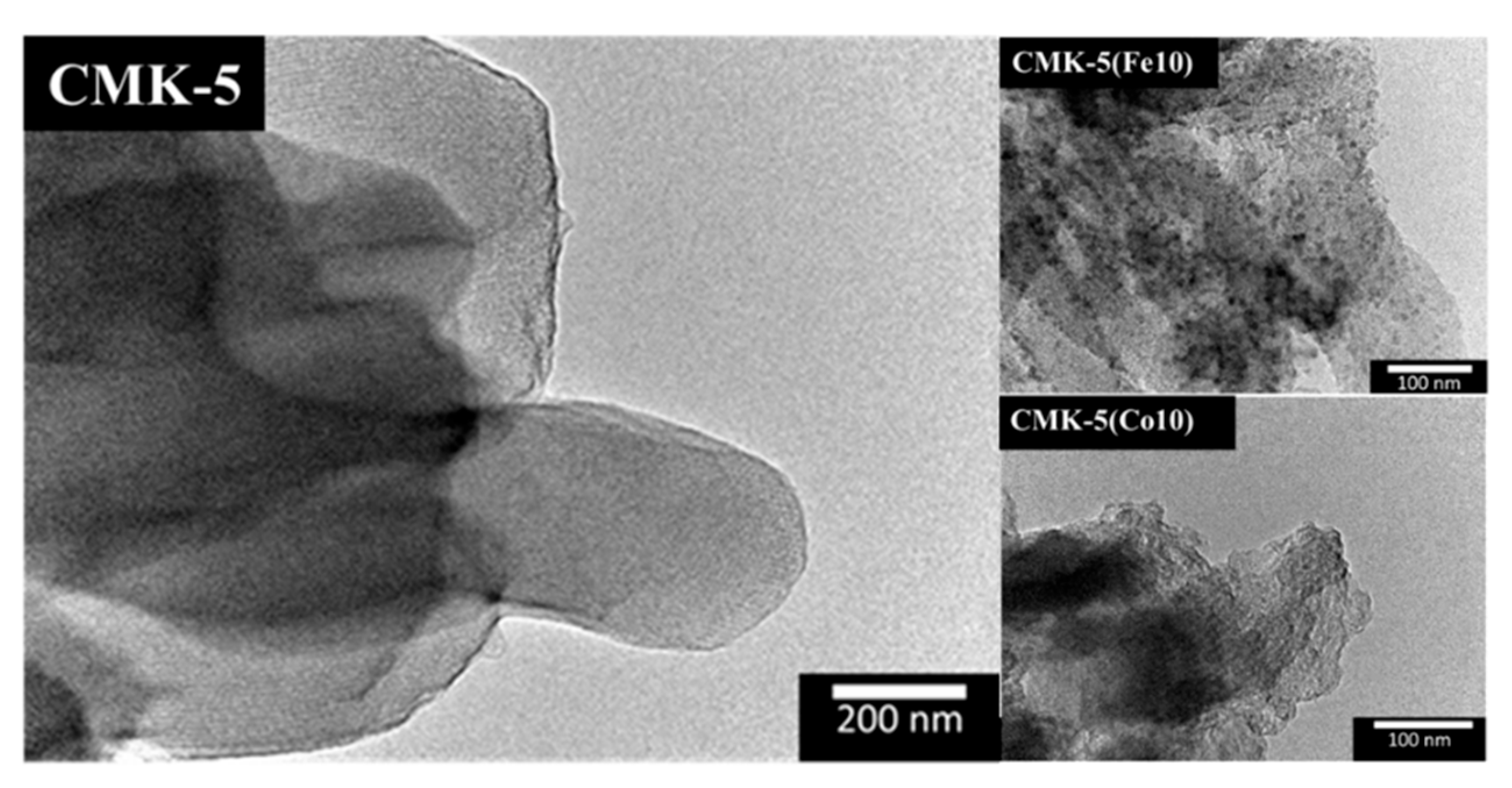
Figure 4 shows the TEM images of pristine CMK-5 and the two impregnated materials. As can be observed, the nanoparticles are distributed across the entire support; however, they are predominantly located outside the porous structure.
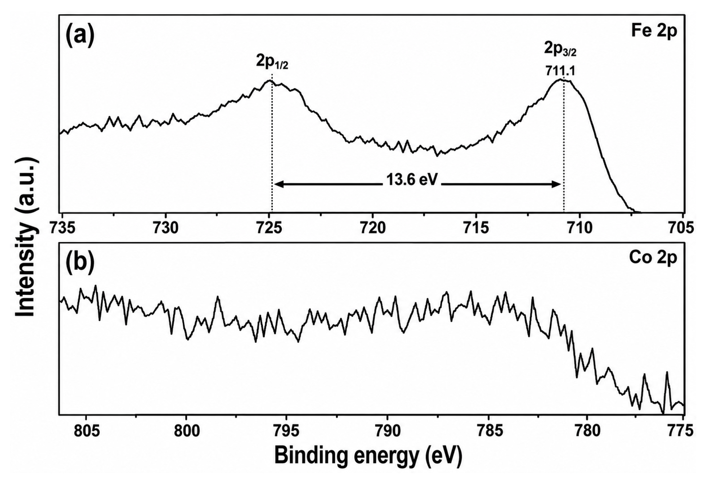
The spectral XPS of CMK-5(Fe10) (Figure 5) clearly confirms the presence of iron. The spectrum displays the 2p3/2 peak at a binding energy of 711.1 eV and the 2p1/2 peak at 724.7 eV, with a spin–orbit splitting of Δ = 13.6 eV, which is characteristic of Fe3+ in Fe2O3. The 2p3/2 peak exhibits a slight shift toward higher binding energies while maintaining the same Δ value, indicating the position of the 2p1/2 component. This shift reflects the chemical environment of Fe2O3, as XPS is highly sensitive to metal–support interactions and to changes in the local electronic structure surrounding the element [35,36].
In contrast to the behavior observed for the iron-containing samples, the XPS analysis of the cobalt-impregnated CMK-5(Co10) material does not detect a Co signal. This absence can be attributed to the surface-sensitive nature of XPS, which typically probes only the outermost few nanometers of the material (~10 nm). Therefore, cobalt species located deeper within the particles or confined inside the mesoporous structure of the CMK-5 support may remain beyond the detection depth of the technique [37]. SEM-EDX analysis and elemental mapping (Figure 3) clearly confirm the presence of cobalt in the catalyst and reveal a homogeneous distribution of the metal throughout the carbon matrix. These observations suggest that cobalt nanoparticles are predominantly located within the internal mesoporous network of the CMK-5 support rather than on the external surface, which explains the absence of a detectable Co signal in the XPS spectra.
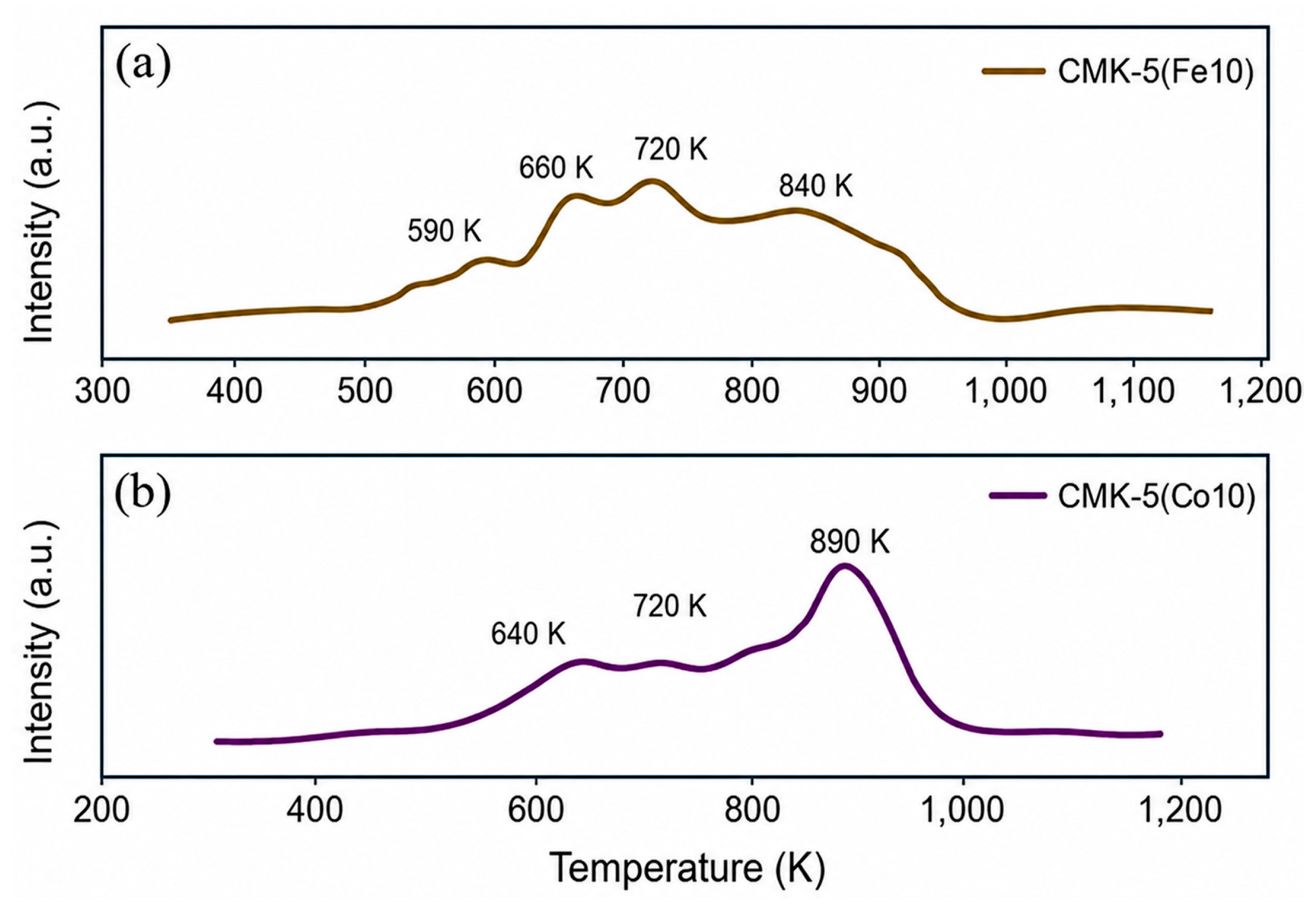
Figure 6a shows the reduction behavior of the iron oxide supported on CMK-5, which exhibits a well-defined sequence of events. Four distinct maxima are observed at 590 K, 660 K, 720 K, and 840 K, which can be attributed to the stepwise reduction of iron oxide particles of different sizes, as also indicated by the particle-size distribution observed in the TEM images. The presence of multiple reduction peaks indicates a heterogeneous population of iron oxide species, likely associated with variations in dispersion, degree of interaction with the carbon support, and local coordination environments. Furthermore, no hydrogen consumption is observed at temperatures above these events, consistent with the inert nature of the CMK-5 carbon framework and its limited participation in redox processes. This behavior reinforces the notion that the carbon support primarily acts as a structurally confining matrix rather than a chemically active phase during the reduction of iron oxide.
In comparison, the reduction behavior of the cobalt-containing material exhibits a distinct pattern that reflects the characteristic redox chemistry of cobalt oxides and their interaction with the CMK-5 support. For CMK-5(Co10) (Figure 6b), two main reduction events are observed at 640 K and 720 K, corresponding to the sequential transformations from Co3O4 to Co2+ and from Co2+ to metallic Co0, respectively. These transitions typically occur over a narrower temperature range than those of iron oxides, highlighting the different reducibility and structural evolution of cobalt species under hydrogen. Additionally, a broad signal detected in all three materials at approximately 900 K may be attributed to hardly reducible cobalt oxide species associated with variations in particle size and morphology, as well as their interaction with the support. The persistence of these high-temperature features suggests the presence of strongly bound cobalt species or particles partially embedded within the carbon matrix. It is important to note that the reduction mechanism of cobalt remains under ongoing investigation, largely due to significant overlap in reduction signals and the coexistence of multiple cobalt oxidation states under reaction conditions [38]. This complexity underscores the sensitivity of cobalt redox behavior to structural confinement, dispersion, and local chemical environment within porous carbon supports.
The hydrogen consumption obtained from the integrated TPR profiles was normalized by the total metal content, yielding values of 1.6 mol H2·mol−1 Fe for CMK-5(Fe10) and 2.0 mol H2·mol−1 Co for CMK-5(Co10) (Table 1). For the Fe-based catalyst, this value is close to the theoretical hydrogen consumption expected for the reduction of Fe2O3 to metallic Fe (1.5 mol H2·mol−1 Fe), suggesting that iron is predominantly present as Fe2O3 species before reduction. In contrast, the Co-based catalyst exhibits a higher hydrogen consumption than the theoretical value expected for the reduction of Co3O4 to metallic Co (1.33 mol H2·mol−1 Co). Similar deviations from theoretical hydrogen consumption have been reported for cobalt catalysts supported on carbon materials, where H2 consumption values exceed the theoretical value. These deviations have been attributed to additional hydrogen uptake associated with hydrogen spillover from cobalt particles to the carbon surface, as well as to the reduction of oxygen-containing surface groups or interfacial Co-O-C species on the carbon support [23,24]. Such phenomena are characteristic of carbon-supported cobalt catalysts and have been widely reported for systems based on carbon nanotubes, carbon spheres, and ordered mesoporous carbons used in Fischer–Tropsch synthesis.

3.2. Fischer–Tropsch Synthesis

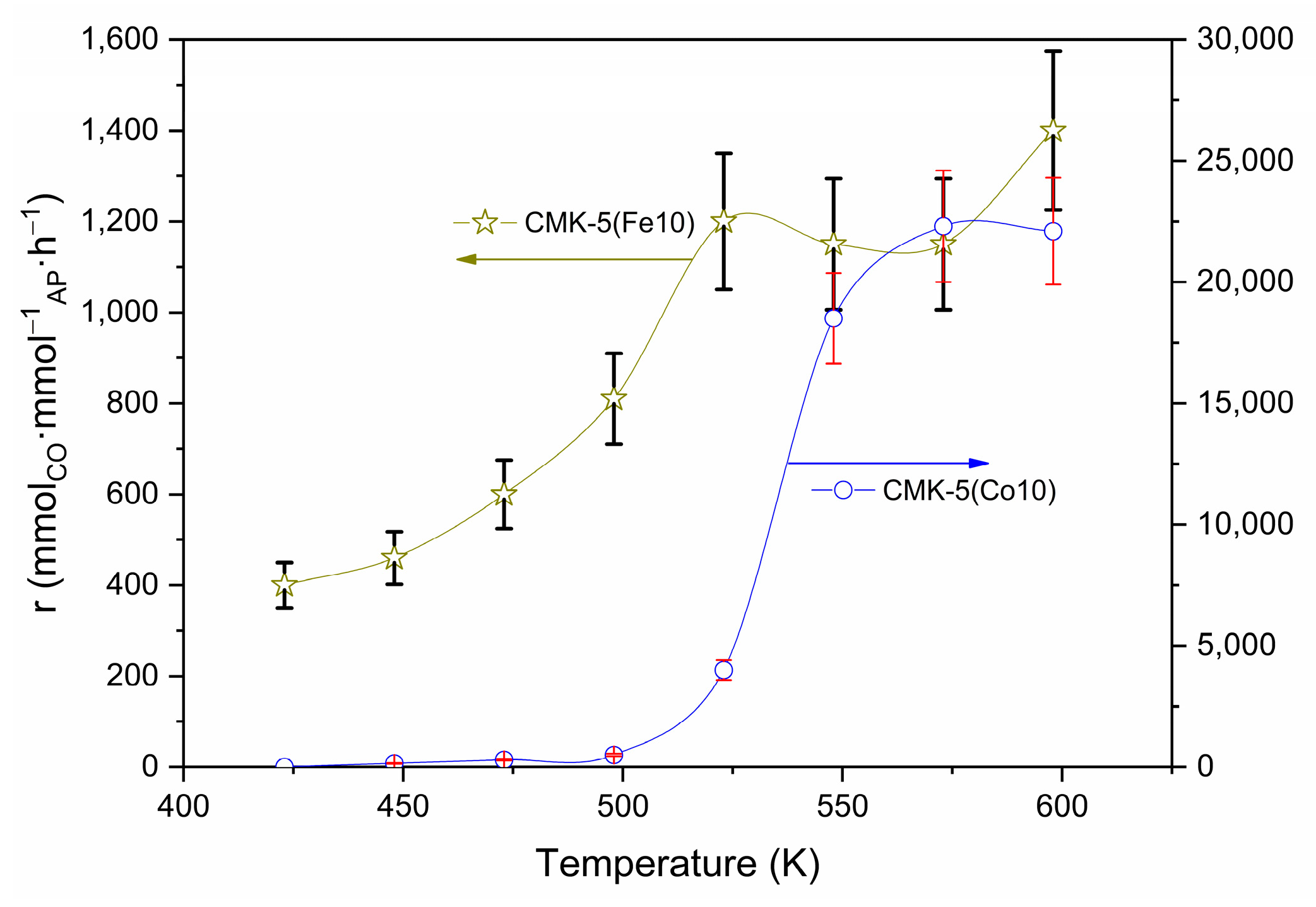
An apparent turnover frequency was estimated by normalizing the CO conversion rate by the total amount of metal present in the catalyst. Although this approximation does not account for the actual number of active sites, it provides a consistent basis for comparing the catalytic performance of the Fe and Co-based catalysts. Figure 7 shows the mean activity at each temperature by Co and Fe catalysts in Fischer–Tropsch synthesis. The activity was calculated with the metal load obtained by XRF (Table 1). CMK-5(Fe10) and CMK-5(Co10) catalysts showed activity at low temperatures (423 and 523 K, respectively) after reaching steady state at 6 h and attaining the mentioned temperatures, and maintaining stable activity thereafter. This fact may be due to the nanometric size of the active phase. The results show that CMK-5(Co10) exhibits the highest activity, approximately 20 times higher than CMK-5(Co10) below 550 K, with no evident catalyst deactivation under the evaluated reaction conditions [9,39]. Such behavior is consistent with previous studies reporting dynamic transformations of the active phase, in which carburization–oxidation–hydrogenation cycles can occur depending on the local chemical potentials of the reactants. These structural rearrangements have been observed not only in bulk transition-metal phases but also in supported catalysts containing metal nanoparticles, highlighting the benefits of these systems under reaction conditions [40,41].
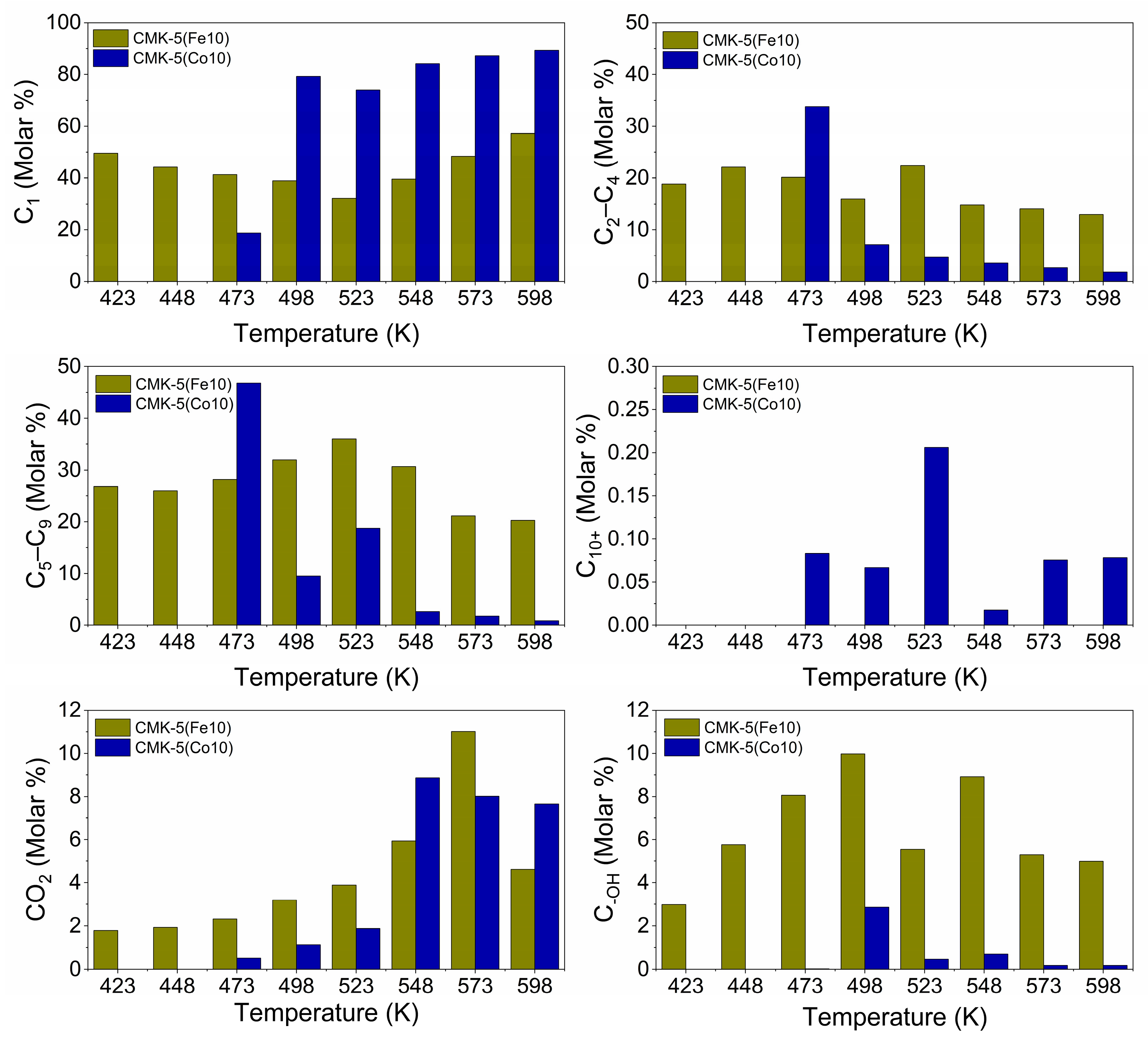
The product selectivity (Figure 8) reveals distinct reaction pathways for both catalysts. The CMK-5(Fe10) catalyst maintains a nearly constant product distribution across the entire temperature range, with methane as the dominant product (~50%), accompanied by contributions of approximately 15% and 25% for the C2–C4 and C5–C9 fractions, respectively. Minor amounts of alcohols are observed at intermediate temperatures (up to ~10%), while CO2 formation becomes more pronounced at higher temperatures. Notably, no formation of heavier hydrocarbons (C10+) is observed within the studied temperature range. This behavior suggests a reaction regime governed by successive hydrogenation steps with limited sensitivity to temperature [40].
In contrast, the CMK-5(Co10) catalyst exhibits a strong temperature-dependent behavior. Methane formation is significant across the entire temperature range, reaching ~80%, which is higher than that observed for the Fe-based catalyst, reflecting enhanced chain-termination reactions. At low temperatures, relatively high selectivity is observed for both C2–C4 and C5–C9 hydrocarbons, reaching approximately 35% and 45%, respectively; however, as the temperature increases, these fractions decrease sharply to values below 5%, indicating a progressive shift toward lighter products. At intermediate temperatures, a small but detectable formation of heavier hydrocarbons (C10+, up to ~0.2%) and alcohols (up to ~2%) is observed, suggesting a limited contribution of chain growth and alcohol formation under these conditions. Finally, as with the Fe-based catalyst, CO2 production increases with temperature, indicating a growing contribution from secondary reactions at elevated temperatures. Overall, these trends reflect a transition from a more distributed product spectrum at low temperatures to a reaction regime increasingly dominated by methane formation at higher temperatures.
Table 2 compares the results of this study with the main findings reported in the literature on the Fischer–Tropsch (FT) reaction using iron or cobalt as the active phase supported on CMK-type materials. However, direct comparisons are challenging due to the different experimental conditions (such as reaction temperature, feed composition, and catalyst amount), which significantly influence catalytic performance. Moreover, no studies in the literature were found reporting catalysts with these active phases impregnated on CMK-5, as used in this work. Under these conditions, the Turnover frequency (TOF) (CMK-5(Fe10)) values of 810–1400 h−1 yielded CO conversions ranging from 2.6% to 4.4%. In addition, TOF values (CMK-5(Co10)) increased from 500 to 22,300 h−1, corresponding to CO conversions ranging from approximately 1.6% to nearly 70% under identical feed and WHSV conditions. This rise in conversion with increasing temperature indicates that the Co catalyst progressively transitions from a strictly kinetic regime to one where high conversion levels begin to dominate the reactor response. That behavior highlights the significantly higher intrinsic activity of cobalt on the CMK-5 support and suggests that other factors, such as may start influencing the overall performance.
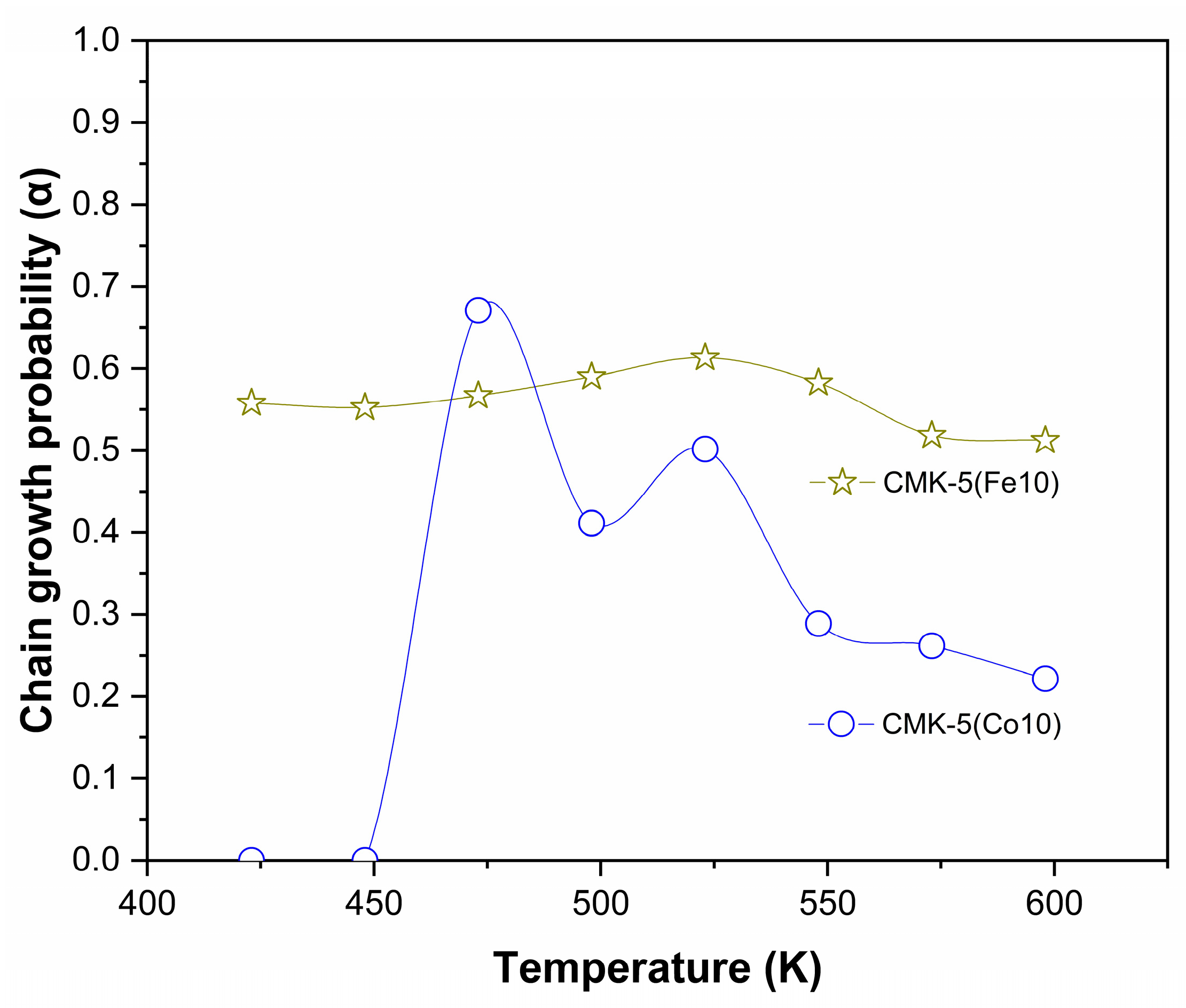
The evolution of α with reaction temperature for both catalysts is presented in Figure 9. It should be noted that the α values reported here correspond to approximate estimations derived from the product distribution and therefore provide a qualitative indicator of chain growth behavior rather than a direct kinetic parameter. The CMK-5(Fe10) catalyst exhibits relatively stable α values in the range of approximately 0.51–0.61 across the studied temperature interval. This behavior is consistent with the selectivity trends discussed above, in which the formation of C5+ hydrocarbons remains relatively constant with increasing temperature. The moderate, nearly temperature-independent α values suggest that the probability of chain propagation on the Fe-based catalyst remains fairly stable across the evaluated reaction conditions, leading to a balanced distribution of light and intermediate hydrocarbons.
In contrast, the CMK-5(Co10) catalyst shows a markedly different trend. At low temperatures, the estimated α values are very small due to the negligible formation of C5+ hydrocarbons, indicating a very low probability of chain growth under these conditions. As the temperature increases, α reaches a maximum at 473 K, which correlates with the highest observed formation of C5–C9 hydrocarbons. However, further increases in temperature lead to a progressive decrease in α, reflecting the shift toward the formation of lighter hydrocarbons, including methane, observed in Figure 8. This behavior indicates that, at higher temperatures, chain termination reactions such as hydrogenation and desorption become more competitive than chain propagation, resulting in a lower probability of chain growth. Thus, the estimated α values are consistent with the experimentally observed product selectivity trends, particularly the higher formation of lighter hydrocarbons at elevated temperatures for the Co-based catalyst.
Table 3 presents the normalized distributions of paraffins and olefins for the different catalytic systems. The CMK-5(Fe10) catalyst exhibits simple, invariant behavior across the entire temperature range, producing paraffins exclusively, indicating that hydrogenation reactions dominate and yield fully saturated products. In contrast, the CMK-5(Co10) catalyst exhibits a temperature-dependent distribution, with the presence of olefins at intermediate temperatures indicating incomplete hydrogenation. As the temperature increases, the olefin content decreases, indicating a progressive shift toward hydrogenation-dominated pathways and a product distribution increasingly composed of saturated hydrocarbons and methane.
Overall, these results indicate that the Fe-based catalyst operates under conditions that favor the complete hydrogenation of surface intermediates. In contrast, the Co-based catalyst exhibits a more complex, temperature-dependent behavior involving competing hydrogenation and chain-termination processes, likely associated with differences in metal–support bonding energies.
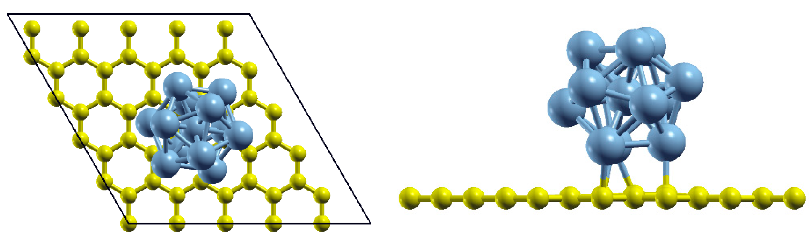
To provide a molecular-level interpretation of these differences, DFT calculations examined the interaction between the metal clusters and the carbon surface. The interaction energy between the metal clusters and the graphene surface was calculated to be −1.96 eV for Co13 and −3.89 eV for Fe13. The calculated energy indicates the energetic stability of the interaction between a metal cluster and a graphene surface. The final state of geometric optimization is shown in Figure 10.
To understand the behavior of the formation of CH4 and C2H4, the reaction pathways of the reactions described from (3) to (8) were calculated through CI-NEB. Here, the graphene surface was not considered, and it was assumed that the surface does not interact with the reactive species on the metal clusters. Although the explicit support may slightly affect adsorption energies through metal–support interactions, the elementary reaction steps are mainly governed by local gas–metal interactions on the cluster. Therefore, the shape of the potential energy surface and the calculated activation barriers are not expected to change significantly. In this context, the isolated cluster model provides a reasonable approximation of the catalytic environment. In Table 4, the binding and adsorption energies of the simulated clusters are reported, illustrating the energetic trends within the system.
The binding and adsorption energies of CH*, CH2*, CH3*, CH4*, and C2H4* on the Fe13 and Co13 metal clusters were computed using the PBE-D3 functional and are shown in Table 4. Overall, Fe13 exhibits stronger interactions with all adsorbates compared with Co13, indicating a higher reactivity toward hydrocarbon fragments. For Fe13, the adsorption energies range from −7.59 eV for CH*, to −0.15 eV for CH4*, with C2H4* showing an adsorption energy of −1.87 eV. In contrast, Co13 presents slightly weak binding, with values from −7.25 eV for CH* to 0.12 eV for CH4*, and an adsorption energy of −1.59 eV for C2H4*. Showing the affinity of Fe13 toward carbon-containing species relative to Co13, which may influence their catalytic behavior in hydrocarbon activation processes. All the reported structures are available in XYZ format in the Supporting Information File (Supplementary Materials).
It is important to note that the computational models employed in this study are based on idealized surfaces that do not fully capture the structural complexity of real catalysts, including variations in particle size, phase composition, and defect presence. Consequently, establishing a direct correspondence between the DFT results and the experimental observations remains nontrivial. In this context, the calculated adsorption energies should be interpreted as providing a qualitative rationalization of the observed support-dependent selectivity trends, rather than a definitive mechanistic validation. The activation barriers and reaction energies for the formation from C* + H* ↔ CH* to CH4* and C2H4* on the Fe13 and Co13 clusters are shown in Table 5. The studied pathways reveal notable differences in their reactivity and preferred pathways. On Fe13, the initial hydrogenation of C* to CH* requires an activation barrier of 1.05 eV with a reaction energy of 0.44 eV, indicating an endothermic step. The subsequent conversion of CH* to CH2* has a lower barrier of 0.30 eV and is slightly exothermic with a reaction energy of −0.15 eV. The CH2* to CH3* step presents a similar barrier of 0.57 eV and a reaction energy of −0.16 eV. Further hydrogenation to CH4* requires overcoming a barrier of 0.72 eV and is strongly exothermic with a reaction energy of −0.75 eV. In contrast, the C2H4* formation pathway on Fe13, involving the coupling of two CH2*, shows a comparatively high activation barrier of 1.34 eV but is nearly thermoneutral with a reaction energy of 0.02 eV. For Co13, the C* to CH* step proceeds with a significantly lower barrier of 0.58 eV and an exothermic reaction energy of minus 0.48 eV, suggesting a more favorable initial hydrogenation.
The CH* to CH2* conversion on Co13 has a barrier of 0.40 eV and an endothermic reaction energy of 0.11 eV. The CH2* to CH3* step occurs with a barrier identical to that of Fe13, 0.57 eV, but is slightly endothermic with a reaction energy of 0.06 eV. The hydrogenation of CH3* to CH4* requires a barrier of 1.20 eV and presents an exothermic reaction energy of 0.43 eV. Finally, the formation of C2H4* on Co13 occurs via a lower activation barrier of 0.48 eV, although the step is exothermic with a reaction energy of −0.48 eV. Here, it is possible to see how Fe13 favors complete hydrogenation toward CH4*, whereas Co13 provides a more accessible pathway for C2H4* formation due to its lower coupling barrier. All the Initial, transition, and Final State are available in Table 6.
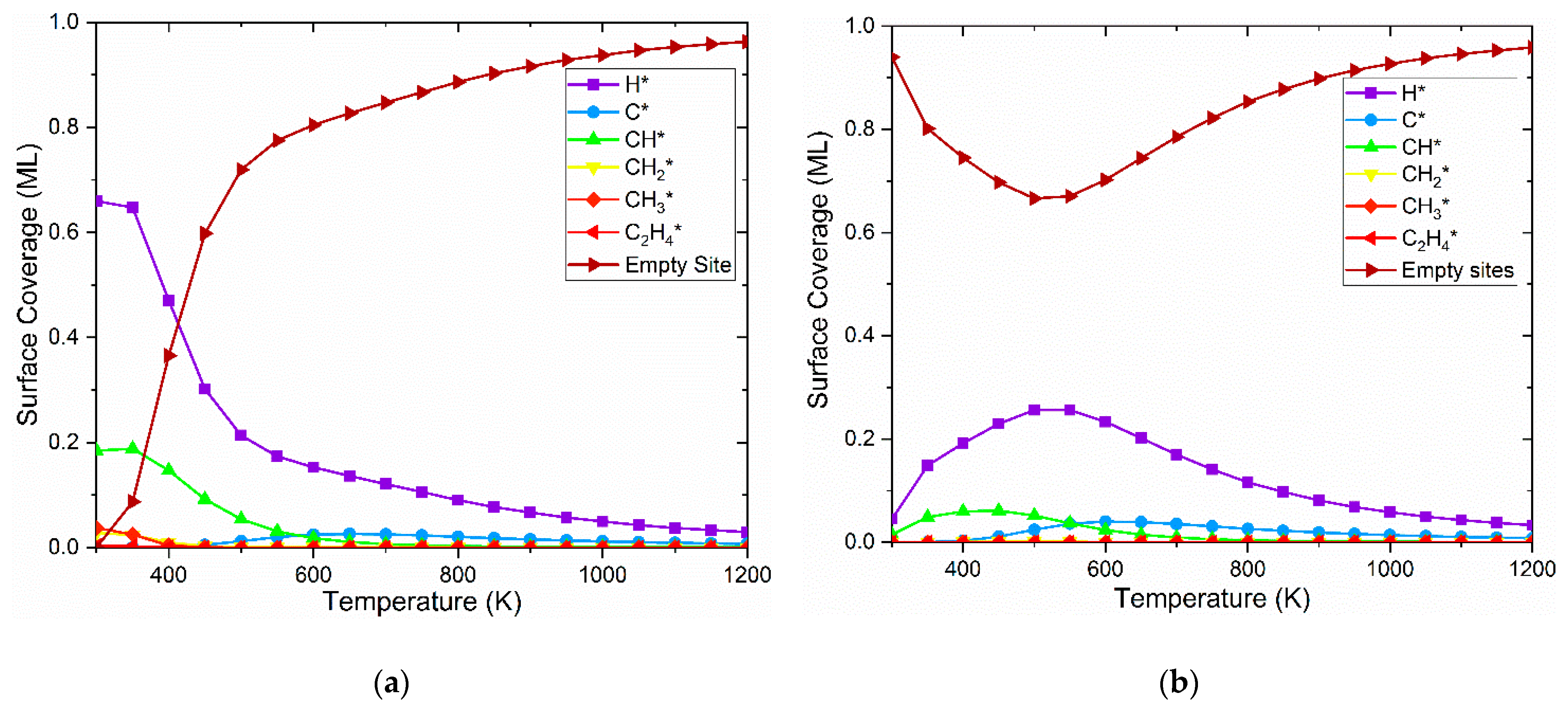
The microkinetic modeling results illustrating the evolution of surface coverage as a function of temperature are presented in Figure 11 for both Co (a) and Fe (b) clusters, considering the reactions 3 to 8. For the Co cluster, the surface at 300 K is predominantly covered by atomic hydrogen (H*) and, to a lesser extent, CH* species. As the temperature increases, a rapid monotonic decrease in these species is observed, accompanied by a corresponding sharp rise in the fraction of empty sites, which becomes the dominant surface feature above 450 K. In contrast, the Fe cluster exhibits a high initial availability of empty sites at 300 K. As the temperature rises, there is a notable accumulation of surface H*, reaching a maximum coverage around 550 K, corresponding to a local minimum in the availability of empty sites. Beyond this temperature, the H* coverage declines, and the surface becomes nearly fully depleted of adsorbates. Overall, the Co surface maintains a significantly higher adsorbate coverage at low temperatures than Fe, while both metals show a complete dominance of empty sites at elevated temperatures above 800 K.
The microkinetic analysis reveals critical differences in the population of surface species that govern reaction selectivity. For the Co cluster, the significantly higher coverage of CH* species at moderate temperatures increases the probability of lateral carbon-carbon interactions, a prerequisite for initiating C–C coupling and chain growth. Conversely, on the Fe cluster, the low concentration of CH* species limits dimerization rates, while the presence of atomic H* on a surface with a higher availability of vacant sites favors the full hydrogenation of isolated carbon intermediates toward CH4*. Thus, the composition of the adsorbed layer suggests that Co tends to favor C–C bond formation, whereas Fe shows the greatest tendency toward methane formation under the studied conditions. The KMC simulations in Figure 11 show that the temperature-dependent surface coverages could influence the number of available active sites, with Co exhibiting a higher fraction of vacant sites and lower accumulation of strongly bound intermediates than Fe. This reduced site blocking leads to faster surface turnover, consistent with the higher intrinsic activities measured experimentally under FTS conditions in Figure 8. Thus, the microkinetic trends predicted by KMC directly correlate with the observed catalytic performance.
The computational results provide a mechanistic framework that is consistent with the experimentally observed catalytic behavior. The stronger interaction of Fe13 clusters with carbon-containing intermediates and the higher barriers to C–C coupling favor successive hydrogenation steps, consistent with the high methane selectivity observed experimentally for the Fe-based catalyst. In contrast, the lower activation barrier for CH2* coupling and the higher surface coverage of CH* species predicted for Co13 clusters facilitate C–C bond formation, supporting the formation of C2–C4 hydrocarbons and olefins observed in the catalytic tests. Therefore, although the computational models are based on simplified cluster representations, they provide a qualitative explanation for the experimental differences in selectivity and paraffins/olefins ratio between Fe- and Co-based catalysts under Fischer–Tropsch conditions. In this comparison, it is also relevant to consider systems supported on carbon matrices, such as CMK-5 (this work), and on mesostructured silica, such as SBA-15, as both supports have different metal–support interaction environments that alter the resulting selectivity patterns.

4. Conclusions

The successful synthesis of iron- and cobalt-based catalysts supported on nanoporous carbon enabled a direct comparison of their catalytic behavior under Fischer–Tropsch conditions. The CMK-5-supported catalysts exhibited higher activity at elevated temperatures, consistent with previously reported trends for analogous silica-supported systems [41]. The CMK-5(Fe10) catalyst produced exclusively paraffins across the evaluated temperature range, whereas CMK-5(Co10) transitioned from paraffin formation at low temperature to selective C3-olefin production at higher temperature, highlighting the distinct reactivity patterns of the two metals.
The combined DFT and KMC analyses provide a mechanistic foundation consistent with these experimental observations. Fe13 clusters exhibit stronger interactions with carbon-containing intermediates and lower reaction energies for successive hydrogenation steps, resulting in a hydrogenation-dominated behavior, where surface carbon intermediates are preferentially converted into methane. In contrast, Co13 clusters present lower activation barriers for the initial hydrogenation of atomic carbon and stabilize partially hydrogenated species, leading to a broader product distribution. KMC simulations further indicate that CH intermediates persist on the Co surface long enough to enable C–C coupling and chain growth. In contrast, rapid hydrogenation on Fe surfaces limits the accumulation of partially hydrogenated intermediates and the formation of more complex products.
The novelty of this work lies in the integrated analysis of catalytic performance and mechanistic modeling, which allows establishing a direct link between surface reactivity, reaction pathways, and product distribution for Fe- and Co-based catalysts supported on mesoporous carbon. This combined approach provides deeper insight into the role of the active metal in determining selectivity under Fischer–Tropsch conditions.
It should be noted that the computational models are based on simplified cluster representations and that the exact nature of the active phase under reaction conditions cannot be fully established. Therefore, the mechanistic insights derived here should be interpreted as a qualitative framework consistent with the experimental observations.
These findings contribute to a better understanding of how metal–support interactions and surface chemistry influence catalytic performance, offering useful guidelines for the rational design of catalysts with tailored selectivity.

Supplementary Materials

The following supporting information can be downloaded at: https://www.mdpi.com/article/10.3390/reactions7020035/s1. Final relaxed structures of CH*, CH2*, CH3*, CH4*, and C2H4* on Co13 and Fe13 clusters in XYZ format.

Author Contributions

Conceptualization, methodology, software, and validation, C.T.-L., K.M.-C., D.B., C.P.-G., S.A.-R. and K.S.; formal analysis, investigation, and data curation, C.T.-L., K.M.-C., J.V.-R., L.R.-C. and S.A.-R.; resources, K.S.; writing—original draft preparation, C.T.-L.; writing—review and editing, K.M.-C., D.B., J.V.-R., L.R.-C., C.P.-G., S.A.-R. and K.S.; visualization, C.T.-L., K.M.-C., D.B., J. V-R., L.R.-C., C.P.-G., S.A.-R. and K.S.; supervision, project administration, and funding acquisition, K.S. All authors have read and agreed to the published version of the manuscript.

Funding

The authors express their gratitude to the Consejo Nacional de Investigaciones Científicas y Técnicas (CONICET) (Grant Number PICT-2016-0501), the Agencia Nacional de Promoción de la Ciencia y la Tecnología (ANPCYT), and the Universidad Nacional de San Luis (UNSL) (PROICO Nº03-1923) in Argentina. K. M-C acknowledges funding from the Marie Skłodowska-Curie COFUND 2022 program under Horizon Europe, funded by the European Research Executive Agency (REA).

Data Availability Statement

The original contributions presented in this study are included in the article. Further inquiries may be directed to the corresponding author.

Conflicts of Interest

The authors declare no conflicts of interest.

References

  1. Li, W.; Lin, Q.; Lv, Y.; Li, H.; Liu, W.; Liu, Y.; Zhang, M.; Men, Z. Optimization Strategy and Research Progress of Iron-Based Fischer–Tropsch Synthesis Catalysts: A Green and Low-Carbon Perspective. Clean Energy 2025, 9, 39–54. [Google Scholar] [CrossRef]
  2. Zhang, Q.; Kang, J.; Wang, Y. Development of Novel Catalysts for Fischer–Tropsch Synthesis: Tuning the Product Selectivity. ChemCatChem 2010, 2, 1030–1058. [Google Scholar] [CrossRef]
  3. Davis, B.H. Fischer−Tropsch Synthesis: Comparison of Performances of Iron and Cobalt Catalysts. Ind. Eng. Chem. Res. 2007, 46, 8938–8945. [Google Scholar] [CrossRef]
  4. ten Have, I.C.; Weckhuysen, B.M. The Active Phase in Cobalt-Based Fischer-Tropsch Synthesis. Chem. Catal. 2021, 1, 339–363. [Google Scholar] [CrossRef]
  5. Khodakov, A.Y.; Griboval-Constant, A.; Bechara, R.; Zholobenko, V.L. Pore Size Effects in Fischer Tropsch Synthesis over Cobalt-Supported Mesoporous Silicas. J. Catal. 2002, 206, 230–241. [Google Scholar] [CrossRef]
  6. Rytter, E.; Holmen, A. On the Support in Cobalt Fischer–Tropsch Synthesis—Emphasis on Alumina and Aluminates. Catal. Today 2016, 275, 11–19. [Google Scholar] [CrossRef]
  7. Valero-Romero, M.J.; Rodríguez-Cano, M.Á.; Palomo, J.; Rodríguez-Mirasol, J.; Cordero, T. Carbon-Based Materials as Catalyst Supports for Fischer–Tropsch Synthesis: A Review. Front. Mater. 2021, 7, 617432. [Google Scholar] [CrossRef]
  8. Chen, Y.; Wei, J.; Duyar, M.S.; Ordomsky, V.V.; Khodakov, A.Y.; Liu, J. Carbon-Based Catalysts for Fischer–Tropsch Synthesis. Chem. Soc. Rev. 2021, 50, 2337–2366. [Google Scholar] [CrossRef] [PubMed]
  9. Ghogia, A.C.; Nzihou, A.; Serp, P.; Soulantica, K.; Pham Minh, D. Cobalt Catalysts on Carbon-Based Materials for Fischer-Tropsch Synthesis: A Review. Appl. Catal. A Gen. 2021, 609, 117906. [Google Scholar] [CrossRef]
  10. Fu, T.; Jiang, Y.; Lv, J.; Li, Z. Effect of Carbon Support on Fischer–Tropsch Synthesis Activity and Product Distribution over Co-Based Catalysts. Fuel Process. Technol. 2013, 110, 141–149. [Google Scholar] [CrossRef]
  11. Oschatz, M.; Lamme, W.S.; Xie, J.; Dugulan, A.I.; de Jong, K.P. Ordered Mesoporous Materials as Supports for Stable Iron Catalysts in the Fischer–Tropsch Synthesis of Lower Olefins. ChemCatChem 2016, 8, 2846–2852. [Google Scholar] [CrossRef]
  12. Oschatz, M.; van Deelen, T.W.; Weber, J.L.; Lamme, W.S.; Wang, G.; Goderis, B.; Verkinderen, O.; Dugulan, A.I.; de Jong, K.P. Effects of Calcination and Activation Conditions on Ordered Mesoporous Carbon Supported Iron Catalysts for Production of Lower Olefins from Synthesis Gas. Catal. Sci. Technol. 2016, 6, 8464–8473. [Google Scholar] [CrossRef]
  13. Oschatz, M.; Hofmann, J.P.; van Deelen, T.W.; Lamme, W.S.; Krans, N.A.; Hensen, E.J.M.; de Jong, K.P. Effects of the Functionalization of the Ordered Mesoporous Carbon Support Surface on Iron Catalysts for the Fischer–Tropsch Synthesis of Lower Olefins. ChemCatChem 2017, 9, 620–628. [Google Scholar] [CrossRef]
  14. Yang, Y.; Jia, L.; Meng, Y.; Hou, B.; Li, D.; Sun, Y. Fischer–Tropsch Synthesis over Ordered Mesoporous Carbon Supported Cobalt Catalysts: The Role of Amount of Carbon Precursor in Catalytic Performance. Catal. Lett. 2012, 142, 195–204. [Google Scholar] [CrossRef]
  15. Yang, Y.; Jia, L.; Hou, B.; Li, D.; Wang, J.; Sun, Y. The Oxidizing Pretreatment-Mediated Autoreduction Behaviour of Cobalt Nanoparticles Supported on Ordered Mesoporous Carbon for Fischer–Tropsch Synthesis. Catal. Sci. Technol. 2014, 4, 717–728. [Google Scholar] [CrossRef]
  16. Ha, K.-S.; Kwak, G.; Jun, K.-W.; Hwang, J.; Lee, J. Ordered Mesoporous Carbon Nanochannel Reactors for High-Performance Fischer–Tropsch Synthesis. Chem. Commun. 2013, 49, 5141–5143. [Google Scholar] [CrossRef]
  17. Sun, Z.; Sun, B.; Qiao, M.; Wei, J.; Yue, Q.; Wang, C.; Deng, Y.; Kaliaguine, S.; Zhao, D. A General Chelate-Assisted Co-Assembly to Metallic Nanoparticles-Incorporated Ordered Mesoporous Carbon Catalysts for Fischer–Tropsch Synthesis. J. Am. Chem. Soc. 2012, 134, 17653–17660. [Google Scholar] [CrossRef]
  18. Asiaee, A.; Benjamin, K.M. A Density Functional Theory Based Elementary Reaction Mechanism for Early Steps of Fischer-Tropsch Synthesis over Cobalt Catalyst. 1. Reaction Kinetics. Mol. Catal. 2017, 436, 218–227. [Google Scholar] [CrossRef]
  19. Asiaee, A.; Benjamin, K.M. A Density Functional Theory Based Elementary Reaction Mechanism for Early Steps of Fischer-Tropsch Synthesis over Cobalt Catalyst. 2. Microkinetic Modeling of Liquid-Phase vs. Gaseous-Phase Process. Mol. Catal. 2017, 436, 210–217. [Google Scholar] [CrossRef]
  20. Cheng, J.; Hu, P.; Ellis, P.; French, S.; Kelly, G.; Lok, C.M. Density Functional Theory Study of Iron and Cobalt Carbides for Fischer−Tropsch Synthesis. J. Phys. Chem. C 2010, 114, 1085–1093. [Google Scholar] [CrossRef]
  21. Montiel-Centeno, K.; Barrera, D.; Villarroel-Rocha, J.; Moreno, M.S.; Sapag, K. Hierarchical Nanostructured Carbons as CO2 Adsorbents. Adsorption 2019, 25, 1287–1297. [Google Scholar] [CrossRef]
  22. Giannozzi, P.; Baroni, S.; Bonini, N.; Calandra, M.; Car, R.; Cavazzoni, C.; Ceresoli, D.; Chiarotti, G.L.; Cococcioni, M.; Dabo, I.; et al. QUANTUM ESPRESSO: A Modular and Open-Source Software Project for Quantum Simulations of Materials. J. Phys. Condens. Matter 2009, 21, 395502. [Google Scholar] [CrossRef] [PubMed]
  23. Cheng, K.; Ordomsky, V.V.; Virginie, M.; Legras, B.; Chernavskii, P.A.; Kazak, V.O.; Cordier, C.; Paul, S.; Wang, Y.; Khodakov, A.Y. Support Effects in High Temperature Fischer-Tropsch Synthesis on Iron Catalysts. Appl. Catal. A Gen. 2014, 488, 66–77. [Google Scholar] [CrossRef]
  24. Sian, N.T.W. First-Principles Study on the AlAsXSb1-X Alloys; Universiti Tunku Abdul Rahman: Kajang, Malaysia, 2022. [Google Scholar]
  25. Perdew, J.P.; Burke, K.; Ernzerhof, M. Generalized Gradient Approximation Made Simple. Phys. Rev. Lett. 1996, 77, 3865–3868. [Google Scholar] [CrossRef]
  26. Grimme, S.; Antony, J.; Ehrlich, S.; Krieg, H. A Consistent and Accurate Ab Initio Parametrization of Density Functional Dispersion Correction (DFT-D) for the 94 Elements H-Pu. J. Chem. Phys. 2010, 132, 154104. [Google Scholar] [CrossRef]
  27. Henkelman, G.; Uberuaga, B.P.; Jónsson, H. A Climbing Image Nudged Elastic Band Method for Finding Saddle Points and Minimum Energy Paths. J. Chem. Phys. 2000, 113, 9901–9904. [Google Scholar] [CrossRef]
  28. Momma, K.; Izumi, F. VESTA 3 for Three-Dimensional Visualization of Crystal, Volumetric and Morphology Data. J. Appl. Cryst. 2011, 44, 1272–1276. [Google Scholar] [CrossRef]
  29. Kokalj, A. Computer Graphics and Graphical User Interfaces as Tools in Simulations of Matter at the Atomic Scale. Comput. Mater. Sci. 2003, 28, 155–168. [Google Scholar] [CrossRef]
  30. Amaya-Roncancio, S.; Linares, D.H.; Duarte, H.A.; Sapag, K. DFT Study of Hydrogen-Assisted Dissociation of CO by HCO, COH, and HCOH Formation on Fe(100). J. Phys. Chem. C 2016, 120, 10830–10837. [Google Scholar] [CrossRef]
  31. Amaya-Roncancio, S.; Rodríguez-Quintero, C.; Páez-González, C.J. Implications of DFT Calculations on Microkinetic Predictions: The Catalytic Decomposition of CH4 on M13 (M = Fe, Ni, Ru, Pd and Pt) Cluster. Comput. Theor. Chem. 2025, 1249, 115265. [Google Scholar] [CrossRef]
  32. Andersen, M.; Panosetti, C.; Reuter, K. A Practical Guide to Surface Kinetic Monte Carlo Simulations. Front. Chem. 2019, 7, 202. [Google Scholar] [CrossRef] [PubMed]
  33. Toncón-Leal, C.F.; Villarroel-Rocha, J.; Silva, M.T.P.; Braga, T.P.; Sapag, K. Characterization of Mesoporous Region by the Scanning of the Hysteresis Loop in Adsorption–Desorption Isotherms. Adsorption 2021, 27, 1109–1122. [Google Scholar] [CrossRef]
  34. Mos, Y.M.; Vermeulen, A.C.; Buisman, C.J.N.; Weijma, J. X-Ray Diffraction of Iron Containing Samples: The Importance of a Suitable Configuration. Geomicrobiol. J. 2018, 35, 511–517. [Google Scholar] [CrossRef]
  35. Moulder, J.; Stickle, W.; Sobol, W.; Bomben, K.D. Handbook of X-Ray Photoelectron Spectroscopy; Perkin-Elmer Corporation: Eden Prairie, MN, USA, 1992. [Google Scholar]
  36. Shah, I.; Adnan, R.; Wan Ngah, W.S.; Mohamed, N.; Taufiq-Yap, Y.H. A New Insight to the Physical Interpretation of Activated Carbon and Iron Doped Carbon Material: Sorption Affinity towards Organic Dye. Bioresour. Technol. 2014, 160, 52–56. [Google Scholar] [CrossRef] [PubMed]
  37. Tan, B.J.; Klabunde, K.J.; Sherwood, P.M.A. XPS Studies of Solvated Metal Atom Dispersed (SMAD) Catalysts. Evidence for Layered Cobalt-Manganese Particles on Alumina and Silica. J. Am. Chem. Soc. 1991, 113, 855–861. [Google Scholar] [CrossRef]
  38. Lin, H.-Y.; Chen, Y.-W. The Mechanism of Reduction of Cobalt by Hydrogen. Mater. Chem. Phys. 2004, 85, 171–175. [Google Scholar] [CrossRef]
  39. Phaahlamohlaka, T.N.; Kumi, D.O.; Dlamini, M.W.; Forbes, R.; Jewell, L.L.; Billing, D.G.; Coville, N.J. Effects of Co and Ru Intimacy in Fischer–Tropsch Catalysts Using Hollow Carbon Sphere Supports: Assessment of the Hydrogen Spillover Processes. ACS Catal. 2017, 7, 1568–1578. [Google Scholar] [CrossRef]
  40. van Santen, R.A.; Markvoort, A.J.; Filot, I.A.W.; Ghouri, M.M.; Hensen, E.J.M. Mechanism and Microkinetics of the Fischer–Tropsch Reaction. Phys. Chem. Chem. Phys. 2013, 15, 17038–17063. [Google Scholar] [CrossRef]
  41. Toncón-Leal, C.F.; Múnera, J.F.; Arroyo-Gómez, J.J.; Sapag, K. Fe, Co and Fe/Co Catalysts Supported on SBA-15 for Fischer-Tropsch Synthesis. Catal. Today 2022, 394–396, 150–160. [Google Scholar] [CrossRef]
  42. Krushynska, A.O.; Gandy, A.S.; Navlani-García, M.; Torres, D.S.; Wu, C.-M.; Oh, J.-S.; Carosio, F. Frontiers in Materials: Rising Stars 2020; Frontiers Media SA: Lausanne, Switzerland, 2021. [Google Scholar]
  43. Kang, S.W.; Kim, K.; Chun, D.H.; Yang, J.-I.; Lee, H.-T.; Jung, H.; Lim, J.T.; Jang, S.; Kim, C.S.; Lee, C.-W.; et al. High-Performance Fe5C2@CMK-3 Nanocatalyst for Selective and High-Yield Production of Gasoline-Range Hydrocarbons. J. Catal. 2017, 349, 66–74. [Google Scholar] [CrossRef]
  44. Li, X.; Nisa, M.U.; Chen, Y.; Li, Z. Co-Based Catalysts Supported on Silica and Carbon Materials: Effect of Support Property on Cobalt Species and Fischer–Tropsch Synthesis Performance. Ind. Eng. Chem. Res. 2019, 58, 3459–3467. [Google Scholar] [CrossRef]
  45. Zhao, Y.; Huang, S.; Wei, L.; Zhang, Y.; Lin, A.; Liu, C.; Li, J. Highly Dispersed CoO on Graphitic Mesoporous Carbon as an Efficient Catalyst for Fischer–Tropsch Synthesis. Ind. Eng. Chem. Res. 2020, 59, 3279–3286. [Google Scholar] [CrossRef]
  46. Bai, J.; Song, M.; Pang, J.; Wang, L.; Zhang, J.; Jiang, X.; Ni, Z.; Wang, Z.; Zhou, Q. Highly Dispersed CoO Embedded on Graphitized Ordered Mesoporous Carbon as an Effective Catalyst for Selective Fischer–Tropsch Synthesis of C5+ Hydrocarbons. Front. Chem. 2022, 10, 849505. [Google Scholar] [CrossRef] [PubMed]
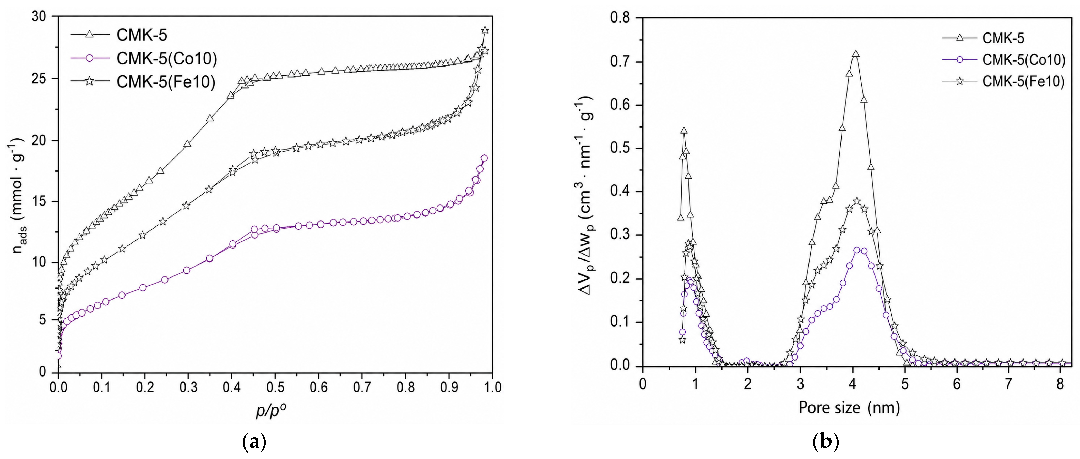
Figure 1. (a) N2 adsorption–desorption isotherms at 77 K and (b) PSD of pristine CMK-5 and CMK-5 impregnated with Fe and Co.
Reactions 07 00035 g001
Figure 2. XRD patterns of the materials: (a) CMK-5 support, (b) CMK-5(Fe10), and (c) CMK-5(Co10).
Reactions 07 00035 g002
Figure 3. SEM images, EDX spectra, and elemental (EDS) maps of the CMK-5 support, CMK-5(Fe10), and CMK-5(Co10).
Reactions 07 00035 g003
Figure 4. TEM micrographs of pristine CMK-5 and Fe- and Co-impregnated CMK-5 samples.
Reactions 07 00035 g004
Figure 5. XPS spectra of (a) CMK-5(Fe10) and (b) CMK-5(Co10).
Reactions 07 00035 g005
Figure 6. TPR profiles of (a) CMK-5(Fe10) and (b) CMK-5(Co10).
Reactions 07 00035 g006
Figure 7. Mean catalytic activity per mole of total metal under FTS reaction conditions of the catalysts. The blue curve (CMK-5(Co10)) corresponds to the right y-axis, whereas the green curve (CMK-5(Fe10)) corresponds to the left y-axis. Black and red bars represent the corresponding error bars.
Reactions 07 00035 g007
Figure 8. Molar selectivity of the catalysts in the FTS reaction tests (423–598 K, 2 MPa).
Reactions 07 00035 g008
Figure 9. Estimated chain growth probability (α) as a function of reaction temperature for CMK-5(Fe10) and CMK-5(Co10) catalysts under Fischer–Tropsch synthesis conditions.
Reactions 07 00035 g009
Figure 10. Top and side views of the interaction of Co13 with the graphene surface. Yellow atom, Carbon. Gray atom, Co.
Reactions 07 00035 g010
Figure 11. Microkinetic modelling of surface species H*, CHn* (n = 0–3) and C2H4*. For (a) Co and (b) Fe (ML: monolayer).
Reactions 07 00035 g011
Table 1. Textural properties of the materials and metal loading of the supported catalyst.
MaterialSBET
(m2·g−1)
VµP
(cm3·g−1)
VPM
(cm3·g−1)
VTP
(cm3·g−1)
Metal Loading
(% wt)
H2 Consumption (mol H2·mol−1 Metal)
CMK-512200.130.620.93
CMK-5(Fe10)9300.080.490.95101.6
CMK-5(Co10)6200.050.330.6382.0
Table 2. Catalytic results in FTS for Fe- or Co-Based Catalysts Supported on CMK-type.
CatalystMetal Content (% wt)Reaction ConditionsT
(K)
TOFCO (h−1)XCO (%)Selectivity (%)αRef.
C1C2–4C5–9C10+CCO2C-OH
CMK-5(Fe10)10W = 0.06–0.07 g diluted with SiC
Pressure: 2 MPa
H2/CO: 2
WHSV = 8100 mL·g1·h−1
4988102.638.915.931.90.03.110.00.59This work
52312003.832.122.436.00.03.95.50.61
54811503.639.614.830.70.05.98.90.58
57311503.648.514.021.10.011.05.30.52
59814004.457.212.920.30.04.64.90.51
Fe/CMK-310.2W = 0.05 g diluted with SiC
Pressure: 2 MPa
H2/CO: 2
WHSV = 8400–33,750 mL·g−1·h−1
573n.d.42.310.13554.9n.d.18.4n.d.n.d.[42]
Fe/CMK-3(0.1)n.d.24.55.628.166.3n.d.25.2n.d.
Fe/CMK-3(0.3)n.d.10.94.216.978.9n.d.20.7n.d.
Fe/CMK-3(0.5)n.d.10.14.827.667.6n.d.21.2n.d.
Fe/CMK-3Sn.d.W = 0.05 g diluted with SiC
Pressure: 2 MPa
H2/CO: 2.1
WHSV = 8000–32,000 mL·g−1·h−1
573n.d.49.712.73948.3n.d.21.5n.d.n.d.[23]
Fe/CMK-3Ln.d.573n.d.38.515.340.744n.d.19.1n.d.
Fe5C2@CMK-320W = 0.08 g diluted
Pressure: 1.5 MPa
H2/CO: 1
WHSV = 30,000 mL·g−1·h−1
593n.d91.423.368.38.3n.d.40n.d.0.90[43]
CMK-5(Co10)8W = 0.06–0.07 g diluted with SiC
Pressure: 2 MPa
H2/CO: 2
WHSV= 8100
mL·g−1·h−1
4985001.679.27.29.50.071.12.90.41This work
523400013.074.04.718.70.21.90.50.50
54818,50058.584.23.52.60.028.90.70.29
57322,30071.787.32.71.80.088.00.20.26
59822,10068.289.31.80.90.087.70.20.22
20Co/CMK-320W = 0.8 g diluted with quartz
Pressure: 2.0 MPa H2/CO: 2
WHSV = 6750
mL·g−1·h−1
50350.435.325.212.562.235.30n.d0.76[44]
Co/OMC tipo CMK-5 (SBA-16 templado)22W = 0.5 g diluted with SiC
Pressure: 1 MPa
H2/CO: 2
WHSV = 3000
mL·g−1·h−1
493n.d49.717.1974n.d.n.d.n.d.n.d.[45]
Co/CMK-320W = 0.8 g diluted with quartz
Pressure: 2.0 MPa H2/CO: 2
WHSV = 6750
mL·g−1·h−1
503n.d4015.22.582.2n.d.n.d.n.d.0.81[10]
Co/CMK-3n.d.W = 0.3 g diluted with quartz
Pressure: 2.0 MPa H2/CO: 2
WHSV = 3600
mL·g−1·h−1
543n.d.18.132.129.224.3n.d.30.7n.d.n.d.[46]
n.d.: not determined.
Table 3. Normalized paraffin and olefin distributions for the catalyst.
Temperature
(K)
CMK-5(Fe10)CMK-5(Co10)
C2=C2C3=C3C2=C2C3=C3
4230.001.000.001.000.000.000.000.00
4480.001.000.001.000.000.000.000.00
4730.001.000.001.000.001.000.960.04
4980.001.000.001.000.001.000.930.07
5230.001.000.001.000.020.980.940.06
5480.001.000.001.001.000.000.840.16
5730.001.000.001.001.000.000.910.09
5980.001.000.001.001.000.000.920.08
Table 4. Binding Energies (eV) and adsorption energies (eV) of C*, CH*, CH2*, CH3*, CH4*, and C2H4* to the metal cluster of Fe and Co.
Metal ClusterDFT ModelC*CH*CH2*CH3*CH4*C2H4*
Fe13 [30]PBE-D3−8.69−7.59−5.77−3.92−0.15−1.87
Co13PBE-D3−8.32−7.25−5.27−3.460.12−1.59
* Denotes an adsorbed species to an adsorption site on the metal cluster.
Table 5. Activation barriers (Eact) and reaction energies (ΔE), minimum energy pathways of CH4* and C2H4* formation on Fe13 and Co13 clusters.
Metal ClusterC* + H* ↔ CH*CH* + H* ↔ CH2*CH2* + H* ↔ CH3*CH3* + H* ↔ CH4*CH2* + CH2* ↔ C2H4*
Eact (eV)ΔE (eV)Eact (eV)ΔE (eV)Eact (eV)ΔE (eV)Eact (eV)ΔE (eV)Eact (eV)ΔE (eV)
Fe13 [30]1.050.440.30−0.150.57−0.160.72−0.751.340.02
Co130.58−0.480.400.110.570.061.200.430.48−0.48
* Denotes an adsorbed species to an adsorption site on the metal cluster.
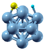
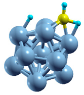
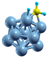
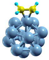
Table 6. Initial, Transition, and Final State of hydrogenation of C* to CH4* on Co13 and C–C coupling.
ReactionInitial StateTransition StateFinal State
C* + H* ↔ CH*Reactions 07 00035 i001Reactions 07 00035 i002Reactions 07 00035 i003
CH* + H* ↔ CH2*Reactions 07 00035 i004Reactions 07 00035 i005Reactions 07 00035 i006
CH2* + H* ↔ CH3*Reactions 07 00035 i007Reactions 07 00035 i008Reactions 07 00035 i009
CH3* + H* ↔ CH4*Reactions 07 00035 i010Reactions 07 00035 i011Reactions 07 00035 i012
CH2* + CH2* ↔ C2H4*Reactions 07 00035 i013Reactions 07 00035 i014Reactions 07 00035 i015
* Denotes an adsorbed species to an adsorption site on the metal cluster.
Disclaimer/Publisher’s Note: The statements, opinions and data contained in all publications are solely those of the individual author(s) and contributor(s) and not of MDPI and/or the editor(s). MDPI and/or the editor(s) disclaim responsibility for any injury to people or property resulting from any ideas, methods, instructions or products referred to in the content.