Review

Photocatalytic Degradation of Methyl Orange in Wastewater Using TiO2-Based Coatings Prepared by Plasma Electrolytic Oxidation of Titanium: A Review

by
Stevan Stojadinović
1,2
1
Faculty of Physics, University of Belgrade, Studentskitrg 12-16, 11000 Belgrade, Serbia
2
Faculty of Forestry, University of Belgrade, KnezaVišeslava 1, 11000 Belgrade, Serbia
Reactions 2025, 6(2), 25; https://doi.org/10.3390/reactions6020025
Submission received: 14 February 2025 / Revised: 21 March 2025 / Accepted: 7 April 2025 / Published: 8 April 2025
(This article belongs to the Special Issue Feature Papers in Reactions in 2025)

Abstract

:
This review analyzes TiO2-based coatings formed by the plasma electrolytic oxidation (PEO) process of titanium for the photocatalytic degradation of methyl orange (MO) under simulated solar irradiation conditions. PEO is recognized as a useful technique for creating oxide coatings on various metals, particularly titanium, to assist in the degradation of organic pollutants. TiO2-based photocatalysts in the form of coatings are more practical than TiO2-based photocatalysts in the form of powder because the photocatalyst does not need to be recycled and reused after wastewater degradation treatment, which is an expensive and time-consuming process. In addition, the main advantage of PEO in the synthesis of TiO2-based photocatalysts is its short processing time (a few minutes), as it excludes the annealing step needed to convert the amorphous TiO2 into a crystalline phase, a prerequisite for a possible photocatalytic application. Pure TiO2 coatings formed by PEO have a low photocatalytic efficiency in the degradation of MO, which is due to the rapid recombination of the photo-generated electron/hole pairs. In this review, recent advances in the sensitization of TiO2 with narrow band gap semiconductors (WO3, SnO2, CdS, Sb2O3, Bi2O3, and Al2TiO5), doping with rare earth ions (example Eu3+) and transition metals (Mn, Ni, Co, Fe) are summarized as an effective strategy to reduce the recombination of photo-generated electron/hole pairs and to improve the photocatalytic efficiency of TiO2 coatings.

1. Introduction

Methyl orange (MO, C14H14N3NaO3S) is a sulfonated azo dye containing sulphonic (–SO3H) and azoic (–N = N–) groups. The sulphonic group in the MO structure is responsible for the high solubility of MO in water. The presence of the azoic group in MO is responsible for high toxicity and carcinogenic and harmful effects on the environment and human and aquatic life at low concentrations. MO dye is widely used in a variety of industries, including paper, textiles, leather, cosmetics, pharmacy, food, etc. [1]. To reduce the harmful effects of MO pollutants while also protecting the environment, they must be removed from wastewater. In recent years, semiconductor photocatalysis has proven to be amongst the best technologies for degrading a wide range of dye pollutants, as it achieves complete mineralization of organic dyes into H2O and CO2 without the formation of secondary hazardous products [2,3].
A variety of semiconductors, such as TiO2, ZnO, CdS, Fe2O3, WO3, V2O5, ZrO2, ZnS, Nb2O5, and others, have been utilized as photocatalysts for the photocatalytic degradation of MO [4,5]. Among them, TiO2 is probably the most studied photocatalyst because of its low cost, non-toxicity, high stability, commercial availability, environmental friendliness, strong oxidizing power, and long-term stability against photo-corrosion [6,7]. The two main disadvantages of TiO2 that prevent its practical use in photocatalysis are its wide energy gap (3–3.2 eV), which restricts its application to the ultraviolet region, and the rapid recombination of photo-induced electron/hole pairs [8,9]. Numerous tactics have been used to increase the photocatalytic efficiency of TiO2. They can be summed up as either lowering the electron/hole recombination rate or altering the energy structure of TiO2, i.e., extending the optical absorption range from the ultraviolet to the visible region [10,11]. To address the shortcoming above, TiO2 can be coupled with narrow band gap semiconductors and doped with metallic and nonmetallic species, rare earth elements, etc. [12,13,14].
TiO2-based photocatalysts are obtainable in two forms: powder and supported on stable substrates (film/coating) [15]. There are some disadvantages to using powder TiO2 photocatalysts, even though they are more photocatalytically efficient due to their higher surface-to-volume ratio than film/coating TiO2-based photocatalysts. Powder photocatalysts reduce the efficiency of photocatalytic reactions by aggregating and scattering light. Furthermore, removing powder photocatalysts from treated wastewater is a complex, time-consuming, and costly process that is unsuitable for practical usage. Using film/coating photocatalysts makes the procedure easier because the photocatalyst only needs to be removed from the treated wastewater.
The plasma electrolytic oxidation (PEO) process has recently been recognized as a valuable technique for producing photocatalytically active oxide coatings for the degradation of organic pollutions [16], primarily on Ti [17,18,19,20,21,22,23,24,25,26,27,28,29,30,31,32,33,34,35,36,37,38,39,40,41,42,43,44,45,46,47,48,49,50,51,52,53,54,55,56] but also on Mg alloys [57,58,59,60,61,62,63,64,65], Al [66,67,68,69,70,71], Ta [72], Nb [73], Zr [74], Zn [75], and brass [76]. PEO is a straightforward, efficient, and environmentally friendly anodizing method that produces oxide coatings on various metals (such as Al, Mg, Ti, Zr, Hf, Ta, Zn, Nb, and W) and their alloys by applying a high voltage beyond the dielectric breakdown threshold. This induces numerous short-lived, transient micro-discharges on the coating surface, accompanied by gas emission [77,78,79]. During these micro-charges, localized high temperatures and pressures are generated, facilitating the formation of oxide coating, mainly composed of substrate oxides, although complex oxides with electrolyte components can also be formed.
In this paper, we have reviewed current research on the photocatalytic application of TiO2-based coatings formed on a titanium substrate by the process of PEO for the degradation of MO. The primary benefits of PEO usage in the production of PEO TiO2-based photocatalysts include low costs, ease of use, and notable energy and time savings, as the processing time is very short (just a few minutes). This is due to the elimination of the annealing step, which is typically required to convert amorphous TiO2 into crystalline phases. PEO allows for the controlled incorporation of electrolyte species into TiO2 coatings during growth, which improves photocatalytic performance. All of these are highly desirable for the purpose of the industrial application of PEO to create TiO2-based photocatalysts.

2. Materials and Methods

The starting material for the preparation of TiO2-based coatings was a rectangular titanium sample (99.95% purity, Alfa Aesar, Haverhill, MA, USA) with dimensions of 25 mm × 10 mm × 0.25 mm. The preparation of titanium samples for PEO includes their ultrasonic cleaning with acetone, drying in a warm air stream, and coating with insulating resin, leaving a surface of 10 mm × 15 mm accessible to the electrolyte. Most of the TiO2-based coatings were formed in a water solution of 10 g/L Na3PO4·12H2O (basic electrolyte-BE) with the addition of SnO2, CdS, Bi2O3, Sb2O3, MnO, NiO, Co3O4, and Eu2O3, particles as well as FeSO4 and NaAlO2 in different concentrations. TiO2/WO3 coatings were formed in a water solution of 10−3 M H4SiW12O40 (12-tungstosilicic acid, WSiA, Merck, Darmstadt, Germany). A current density of 150 mA/cm2 was applied for PEO. The PEO experimental setup is detailed in Ref. [80].
The TiO2-based coatings were characterized by scanning electron microscopy (SEM, JEOL 840A, Tokyo, Japan) with energy-dispersive X-ray spectroscopy (EDS, Oxford INCA, Abingdon, UK), X-ray diffraction (XRD, Rigaku Ultima IV, Tokyo, Japan), Raman spectroscopy (TriVista 557 Raman system, S&I GmbH, Warstein, Germany), X-ray photoelectron spectroscopy (XPS, Kratos AXIS Supra, Kratos Analytical Limited, Manchester, UK), X-ray fluorescence (XRF, Shimadzu XRF-1800, Shimadzu Corporation, Kyoto, Japan), photoluminescence (PL, Horiba JobinYvon, Fluorolog FL3-22, Edison, NJ, USA), and diffuse reflectance spectroscopy (DRS, Shimadzu UV-3600, Tokyo, Japan).
The photocatalytic potential of the TiO2-based coatings was assessed by the degradation of 8 mg/L solution of MO. MO was chosen as a model for an organic dye because its degradation by various photocatalysts can only be monitored by UV–Vis spectroscopy and no sophisticated analytical techniques are required. The experimental setup for photocatalytic measurements is described in Ref. [74]. The photocatalytic reactor was a double-walled glass vessel cooled with water. The original MO solution and samples were placed in the dark for one hour to reach the equilibrium adsorption–desorption between the photocatalyst and the MO. Then, the TiO2-based samples were placed on a stainless steel holder that was 5 mm above the bottom of the reactor. The 10 cm3 MO solution was mixed using a magnetic stirrer. The samples were exposed to a 300 W light source (OSRAM ULTRA-VITALUX UV-A, OSRAM, Garching, Germany) located 25 cm above the solution’s surface. The photocatalytic activity (PA) of the TiO2-based samples was measured by the degradation of MO after appropriate light exposure. The maximum absorbance peak of MO at 464 nm was measured by the UV–Vis spectrometer (Thermo Electron Nicolet, Evolution 500, Thermo Fisher Scientific Inc., Cambridge, UK). A standard curve was employed to convert the absorbance into a MO concentration, demonstrating a linear correlation between the concentration and absorbance at 464 nm.

3. Results

3.1. PA of TiO2 Coatings

Figure 1a displays the potential–time characteristics for titanium anodization in BE at a constant current density of 150 mA/cm2. The fairly uniform growth of a compact oxide layer is correlated with a linear increase in the anodization potential in region I. A strong electric field (~107 V/cm) facilitates the migration of O2−/OH and Ti4+ ions across the oxide, causing an oxide layer to grow at the interfaces between Ti/oxide and oxide/BE. The following general reaction leads to the formation of the initial oxide layer on the surface of titanium:
Ti + 2H2O → TiO2 + 4H+ + 4e
A deviation from the linearity of the potential–time characteristic signifies the dielectric breakdown (the onset of PEO), which marks the end of the uniform thickening of the film. Following the breakdown, the potential of anodization rises steadily, and a significant number of tiny micro-discharges that are uniformly spaced across the sample surface emerge (region II). Further anodization yields a stable value for the anodization potential (region III) and spark micro-discharges. Oxide layers are formed in a series of steps during the micro-discharges [81]. The loss of dielectric stability in a low conductivity region leads to the formation of a series of separate micro-discharge channels in the oxide layer. Due to the high temperatures at the micro-discharge sites, the titanium melts away from the substrate, penetrates the micro-discharge channels, and reacts with the electrolyte components. The reaction products are ejected from the micro-discharge channels onto the coating surface, where they rapidly solidify in contact with the low-temperature electrolyte. The PEO involves repeating this process to gradually increase the thickness of the coating (Figure 1a).
Figure 1b displays the SEM images of the surface coatings formed at various PEO times. The surface of the coatings is embellished with numerous micro-discharge channels of varying sizes and shapes, along with areas formed by the rapid cooling of molten material. In the PEO of titanium, it is typical that as the PEO time and coating thickness increase, the number of micro-discharge channels and micro-pores decreases while their size increases [82].
The XRD patterns of the PEO coatings in Figure 1b are shown in Figure 1c. The coatings were crystalline and composed of an anatase phase of TiO2 (PDXL DB Card No. 9008213). Elemental titanium originates from the substrate as a result of X-rays passing through the porous oxide coating and reflecting off it.
The optical absorption, PA after 8 h of irradiation, and a schematic representation of the photocatalytic degradation mechanism are shown in Figure 2. TiO2 coatings manifest a broad absorption band in the mid-UV region below 382 nm (Figure 2a). This band gap arises from intrinsic optical transitions between the energy levels of Ti and O. The Kubelka–Munk function was employed to calculate the band gap energy of the TiO2 coatings:
F ( R ) = ( 1 R ) 2 2 R = α S
where R = 10A is the reflectance, A is the absorbance, α and S are the absorption and scattering coefficients, respectively. The following equation describes the energy dependence of the α in semiconductors near the absorption edge:
α ( h ν E g ) η h ν
In this equation, ν represents the incident photon frequency, h is the Planck constant, and Eg is the optical absorption edge energy. The exponent η indicates the type of optical transition caused by photon absorption (η = 1/2 for the direct transition and η = 2 for the indirect transition). To calculate the band gap values in anatase TiO2 coatings, we used a plot [F(R) · ]1/2 vs. [83], extrapolating the linear region of the Tauc plot to the intersection with the —axis (Figure 2b). The calculated Eg is around 3.15 eV.
Although the coatings contain the anatase phase of TiO2, the most photocatalytically active phase, they show low efficiency in the photodegradation of MO. After 120 s of TiO2 formation, PA increases slowly with an increasing PEO time. Relative to the normal hydrogen electrode (NHE), the edges of the valence band (VB) and conduction band (CB) for anatase TiO2 are approximately 2.83 V and −0.37 V, respectively [84]. The mechanism of MO degradation by the process of photocatalysis is shown in Figure 2d. The absorption of photons with energies exceeding the band gap of TiO2 activates the material. The electrons (e) move from the VB to the CB of the TiO2 as a result of the absorption of the photons and form positive holes (h+) in the VB (Equation (4)):
TiO 2 + h ν TiO 2   ( e + h + )
Photo-generated electron/hole pairs can recombine, releasing heat or photons:
TiO 2 ( e + h + ) TiO 2 + heat   ( photons )
or they can migrate to the surface of the catalyst and participate in redox reactions [7]:
h + + H 2 O H + + H O
h + + OH H O
e + O 2 O 2
O 2 + H + HO 2
HO 2 + HO 2 H 2 O 2 + O 2
e + H 2 O 2 H O + OH
H 2 O 2 + O 2 H O + OH + O 2
As a result, hydroxyl radicals (HO•) are generated. These powerful, non-selective oxidizing agents can lead to the partial or complete degradation of organic compounds when the VB holes react with water or hydroxyl ions. At the same time, excited electrons in the CB react with oxygen molecules and form reactive anion superoxide radicals ( O 2 ) along with hydrogen peroxide radicals ( HO 2 ) and hydrogen peroxide (H2O2). Highly reactive species, such as HO•, HO 2 and O 2 , react with MO and lead to their degradation.

3.2. PA of TiO2 Coupled with Narrow Band Gap Semiconductors

The coupling of TiO2 with semiconductors with a suitable band edges position and lower band gap compared to TiO2 (WO3, SnO2, CdS, Sb2O3, Bi2O3, etc.) is a very effective way to improve the photocatalytic efficiency of TiO2 due to two factors: (i) semiconductors with a narrow band gap are employed as photosensitizers for visible light; (ii) the band level positions of the coupled semiconductors minimize the recombination of the electron/hole pairs generated by light and facilitate the transfer of electrons and holes between the two semiconductors [85].

3.2.1. PA of TiO2/WO3 Coatings

WO3 is an inexpensive n-type semiconductor with a relatively small band gap (2.4–2.8 eV), low toxicity, and stability, and it is one of the most significant materials that can be coupled with TiO2 to enhance the photocatalytic activity of TiO2 [86,87]. The small band gap of WO3 enables more efficient utilization of solar light but also leads to an increase in the recombination rate of photo-generated electron/hole pairs, which affects the PA of WO3. It has been shown that TiO2/WO3 mixed oxides exhibit higher PA compared to their single components. When the TiO2/WO3 composites are excited by solar light, photo-generated electrons from the CB of the TiO2 can move to the CB of WO3. Simultaneously, the holes can move from the VB of WO3 to the VB of TiO2. The separation effect enhances the photocatalytic efficiency by minimizing the recombination of the photo-generated electron/hole pairs.
TiO2/WO3 coatings are the most studied system formed by PEO of titanium for the photocatalytic degradation of various organic dyes, most commonly methylene blue and MO [36,42,46,50,51,52,54,56]. Alkaline electrolytes supplemented with sodium tungstate are the most commonly used for the creation of TiO2/WO3 coatings. PEO on titanium in WSiA also allows the formation of very efficient TiO2/WO3 photocatalysts in a very short time [50]. Figure 3 shows SEM micrographs, the EDS composition, XRD patterns, and the light-harvesting properties of the coatings formed in WSiA at different PEO times.
The PEO time has a significant influence on the morphology of the coatings formed (Figure 3a). With an increasing PEO time, the number of micro-discharge channels decreases while their diameter increases. A longer PEO time causes a larger amount of molten oxidized metal to be ejected from the micro-discharge channels and solidified when it comes into contact with the electrolyte, resulting in rougher surfaces. The coatings consist of Ti from the substrate and O and W from the electrolyte (Figure 3b). The proportion of W in the coatings increases with PEO time while the proportion of Ti decreases.
The XRD patterns of the coatings are shown in Figure 3c. The coatings are crystallized and consist of WO3 and anatase TiO2. It is evident that an increase in PEO enriches the coatings with WO3. The elemental Ti originates from the substrate, and its intensity decreases with the duration of PEO, indicating an increase in coating thickness. These results are consistent with the EDS data (Figure 3b). Raman measurements confirm the presence of WO3 and anatase TiO2 in the coatings formed in WSiA (see Figure 3 in Ref. [42]). Figure 3d shows the DRS spectra for TiO2/WO3 coatings. Compared to pure TiO2, the TiO2/WO3 coatings show a distinct redshift, with the shift to higher wavelengths correlating with the duration of the PEO. The redshifts in the DRS of TiO2/WO3 coatings are attributed to the formation of new energy levels resulting from the W-O-Ti bonds created during PEO [54].
Figure 4a shows the PA during MO photodegradation with TiO2/WO3 and pure TiO2 coatings. The PA of the TiO2/WO3 coatings is influenced by the PEO time, with a decrease in PA as the PEO time is extended. Some TiO2/WO3 coatings exhibit higher PA than pure TiO2, particularly with shorter PEO times (30 s, 60 s, and 90 s), which are linked to these increased activities. However, as the PA process time increases (180 s, 300 s, and 600 s), the PA drops significantly, falling below that of pure TiO2.
Numerous factors influence the effectiveness of photocatalytic PEO materials, including their morphology, crystal structure, chemical composition, light absorption capacity, and the ability of the photocatalyst to generate long-lived electrons and holes that enable reduction and oxidation reactions, respectively [16]. Clearly, the decrease in the number of micro-discharge channels and/or the agglomeration of the molten materials on the surface (Figure 3a) leads to a decrease in PA. In addition, the decrease in PA with an increasing PEO process time can be attributed to an increase in the WO3 content in the coatings (Figure 3b,c). The DRS results show that TiO2 coatings containing WO3 exhibit a significant redshift compared to pure TiO2 (Figure 3d). The shift to higher wavelengths corresponds to the duration of the PEO process. Although the useful spectral range for photocatalysis was extended, TiO2/WO3 coatings formed by the PEO process show weak photocatalytic activity for 180 s, 300 s, and 600 s, suggesting that WO3 is the major contributor to the photocatalytic reaction. It is likely that the prolonged PEO leads to thicker TiO2/WO3 coatings with a low effectiveness factor, making deeper layers of the coatings inaccessible to light.
The PL spectral measurements confirm this assumption (Figure 4b). PL is a useful technique to explain the mechanism of photocatalysis, as it can reveal the recombination rate of photo-generated electron/hole pairs [88]. The increase in PL intensity corresponds to a decrease in the PA of the coatings, indicating rapid electron/hole recombination. The photocatalytic activities (Figure 4a) align with the PL results. Coatings formed at PEO times of 30 s, 60 s, and 90 s show a lower PL intensity and follow the order of PA. The improvement in PA is achieved by the significant contribution of TiO2/WO3 centers, which enables the transfer of photo-generated electrons from the CB of TiO2 to the lower-lying CB of WO3 (Figure 4c). The positive holes move towards the VB of TiO2, leading to a decrease in the electron/hole recombination rate. The high PL intensity corresponds to the coatings formed at PEO times of 180 s, 300 s, and 600 s, and the PA is lower than that of pure TiO2. This result, together with the DRS data, confirms a significant involvement of WO3 centers in the reaction since the CB and VB of WO3 are close to each other, leading to a high electron/hole recombination rate.

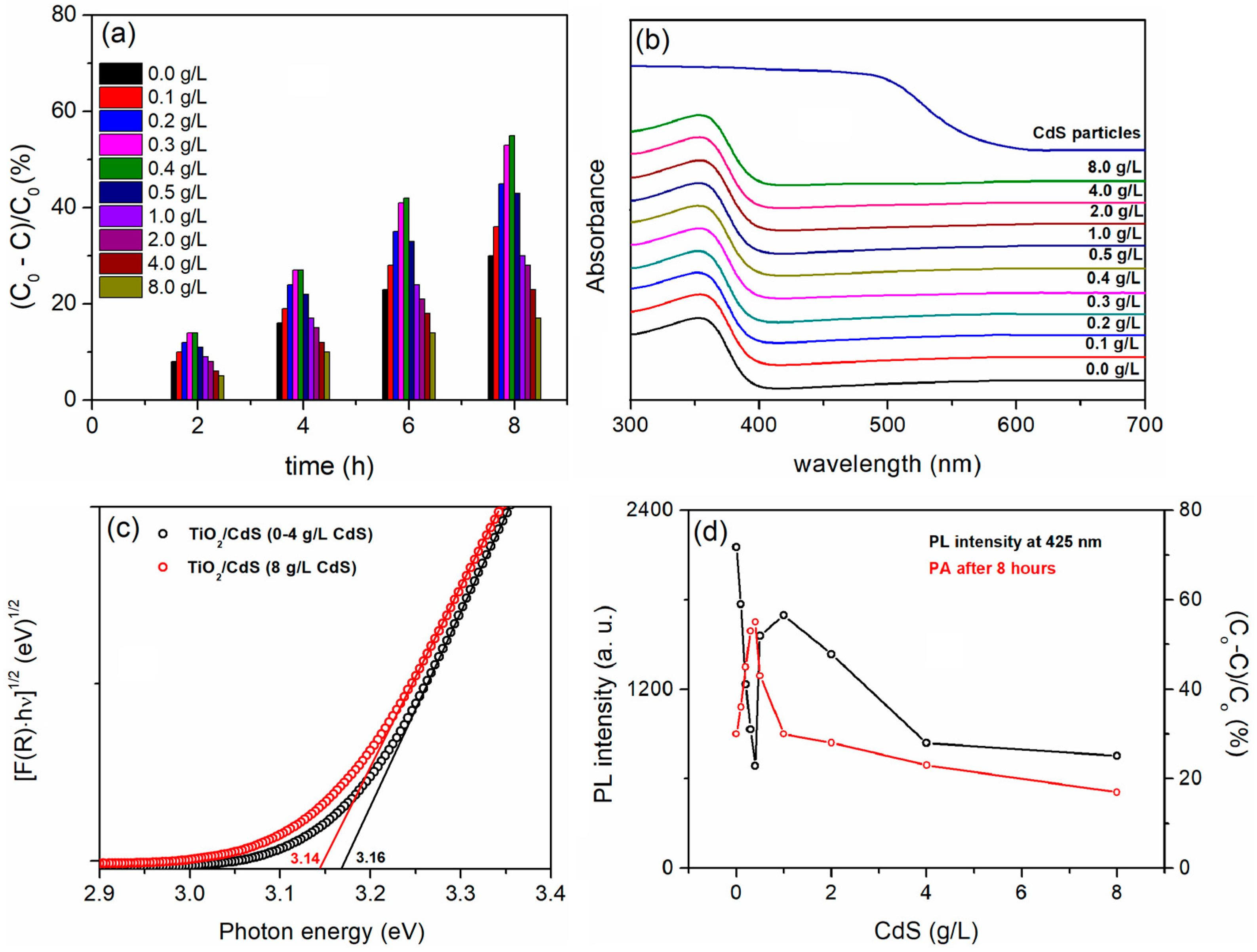
3.2.2. PA of TiO2/CdS Coatings

Due to relatively low band gap energy (~2.3 eV), CdS enhances the separation of photo-generated electron/hole pairs and improves visible light absorption when combined with TiO2. These factors collectively enhance the photocatalytic activity of the TiO2/CdS system [89]. SEM micrographs, XRD patterns, Raman spectra, and the Cd/Ti ratio of the coatings formed by PEO for 2 min in BE with added CdS particles at different concentrations are shown in Figure 5.
The amount of CdS particles in BE does not significantly affect the morphology of the coatings (Figure 5a). The well-defined diffraction peaks in the well-crystallized coatings represent the anatase phase of TiO2 (Figure 5b). Since the CdS are present in low concentrations and uniformly distributed in the TiO2 coatings, no CdS peaks are observed in the XRD patterns. Figure 5c shows the Raman spectra of the CdS particles and the coatings formed in BE and in BE + 8 g/L CdS particles. The Raman spectrum of the CdS particles shows a strong band at 296 cm−1 for the first-order longitudinal optical phonon (1LO) and a band at 592 cm−1 for the second-order optical phonon (2LO) [90]. The Raman spectrum of the pure TiO2 coating shows dominant modes at 144 cm−1 (Eg(1)), 197 cm−1 (Eg(2)), 395 cm−1 (B1g(1)), 514 cm−1 (A1g, B1g(2)), and 637 cm−1 (Eg(3)), which correspond to the active Raman modes of the anatase phase [91]. The Raman spectrum of the coatings prepared in BE with the added CdS confirms the presence of CdS particles in the TiO2 coatings, displaying bands from both the TiO2 coating and CdS particles. The Ti/Cd ratio, obtained from wavelength dispersive XRF measurements (Figure 5d), shows that the CdS content in the coatings increases with the concentration of CdS particles in BE. This suggests that the CdS particles’ concentration in BE regulates the amount of CdS particles incorporated into the TiO2 coating.
Figure 6a shows the PA of TiO2/CdS coatings. TiO2/CdS coatings formed in BE with the addition of CdS particles up to 0.5 g/L outperform the pure TiO2 coating, with the highest PA observed for the coating formed in BE with 0.4 g/L CdS particles. A high concentration of CdS particles in BE significantly reduces PA, with values even lower than those of pure TiO2. Since the CdS particles that are incorporated in the TiO2 coatings have a negligible influence on the morphology and phase structure, the main contribution of CdS particles to PA may be either to extend the optical absorption range of TiO2/CdS coatings or to prevent the fast recombination of photo-generated electron/hole pairs. The DRS spectra of the pure CdS particles and the resulting coatings are shown in Figure 6b. Although the band edge of the CdS particles is around 570 nm, the TiO2/CdS coatings do not show a noticeable shift of the absorption band edge into the visible light region. The calculated band gap energy for all TiO2/CdS coatings is approximately 3.16 eV, except for the coating prepared in BE with 8 g/L CdS particles, which has a slightly lower band gap energy of about 3.14 eV (Figure 6c). The lack of an adsorption shift could be due to the low concentration of CdS particles incorporated in the coatings, which means that the CdS particles inhibit the recombination of photo-generated electron/hole pairs. Conversely, an excessively high concentration of CdS particles in the TiO2 coatings leads to an increase in electron/hole pair recombination centers, ultimately reducing the PA.
The PL emission of the prepared coatings excited at 350 nm and monitored at 425 nm is shown in Figure 6d [38]. When increasing the concentration of CdS particles in the BE to 0.4 g/L, a decrease in PL intensity is observed, while further increasing the concentration of CdS particles in the electrolyte to 1.0 g/L leads to an increase in PL intensity. These findings are consistent with PA, as the decrease in PL intensity corresponds to an increase in PA, indicating a slower recombination of electron/hole pairs. At higher concentrations of CdS particles in the BE (2 g/L or higher), a simultaneous decrease in PL intensity and PA may be attributed to the increased presence of CdS dopants, which act as capture centers for photo-induced electrons [88].

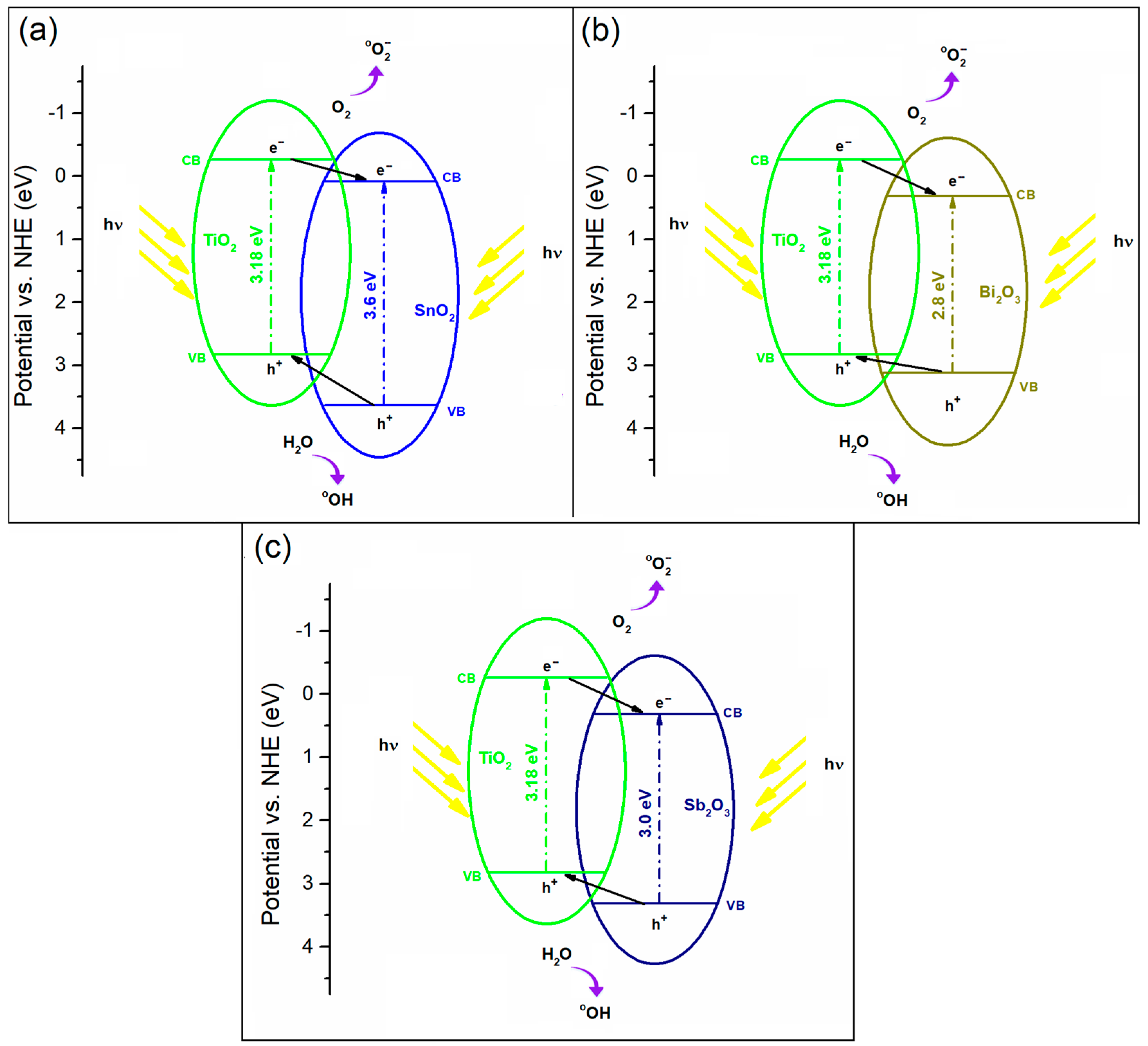
3.2.3. PA of TiO2/SnO2, TiO2/Bi2O3, and TiO2/Sb2O3 Coatings

SnO2, Bi2O3, and Sb2O3 are good candidates for coupling with TiO2 because the upper edge of the VB and the lower edge of the CB of SnO2, Bi2O3, and Sb2O3 are lower than those of TiO2 (Figure 7) [31,32,41]. The photo-generated electrons can move from the CB of TiO2 to that of SnO2, Bi2O3, or Sb2O3, and the photo-generated holes move in the opposite direction between the VBs. As a result, the overall PA of TiO2/SnO2, TiO2/Bi2O3, and TiO2/Sb2O3 coatings are higher than that of their individual components, as the recombination rate of electron/hole pairs in TiO2, SnO2, Bi2O3, or Sb2O3 semiconductors is reduced.
The influence of SnO2, Bi2O3, and Sb2O3 particles on the morphology, chemical, and phase compositions of TiO2/SnO2, TiO2/Bi2O3, and TiO2/Sb2O3 coatings is similar to that of TiO2/CdS [31,32,41]. The PA of the formed coatings is determined by the concentrations of SnO2, Bi2O3, and Sb2O3 particles added to the BE, i.e., by their incorporation into TiO2 coatings (Figure 8a). The highest PA of TiO2/SnO2, TiO2/Bi2O3, and TiO2/Sb2O3 was observed for the coatings formed in BE with the addition of 0.3 g/L SnO2, 1.2 g/L Bi2O3, and 0.75 g/L Sb2O3 particles, respectively. The DRS spectra of the TiO2/SnO2, TiO2/Bi2O3, and TiO2/Sb2O3 coatings in Figure 8b show that the coatings exhibit no recognizable shift in the absorption band toward the visible light range. This result indicates that SnO2, Bi2O3, and Sb2O3 particles incorporated into TiO2 coatings prevent the fast recombination of photo-generated electron/hole pairs, consistent with the PL measurements (Figure 8c). Indeed, the PL emission spectra of TiO2 and the most photocatalytically active TiO2/SnO2, TiO2/Bi2O3, and TiO2/Sb2O3 coatings excited with 350 nm show a decrease in the PL intensity of the TiO2/SnO2, TiO2/Bi2O3, and TiO2/Sb2O3 coatings compared to TiO2.

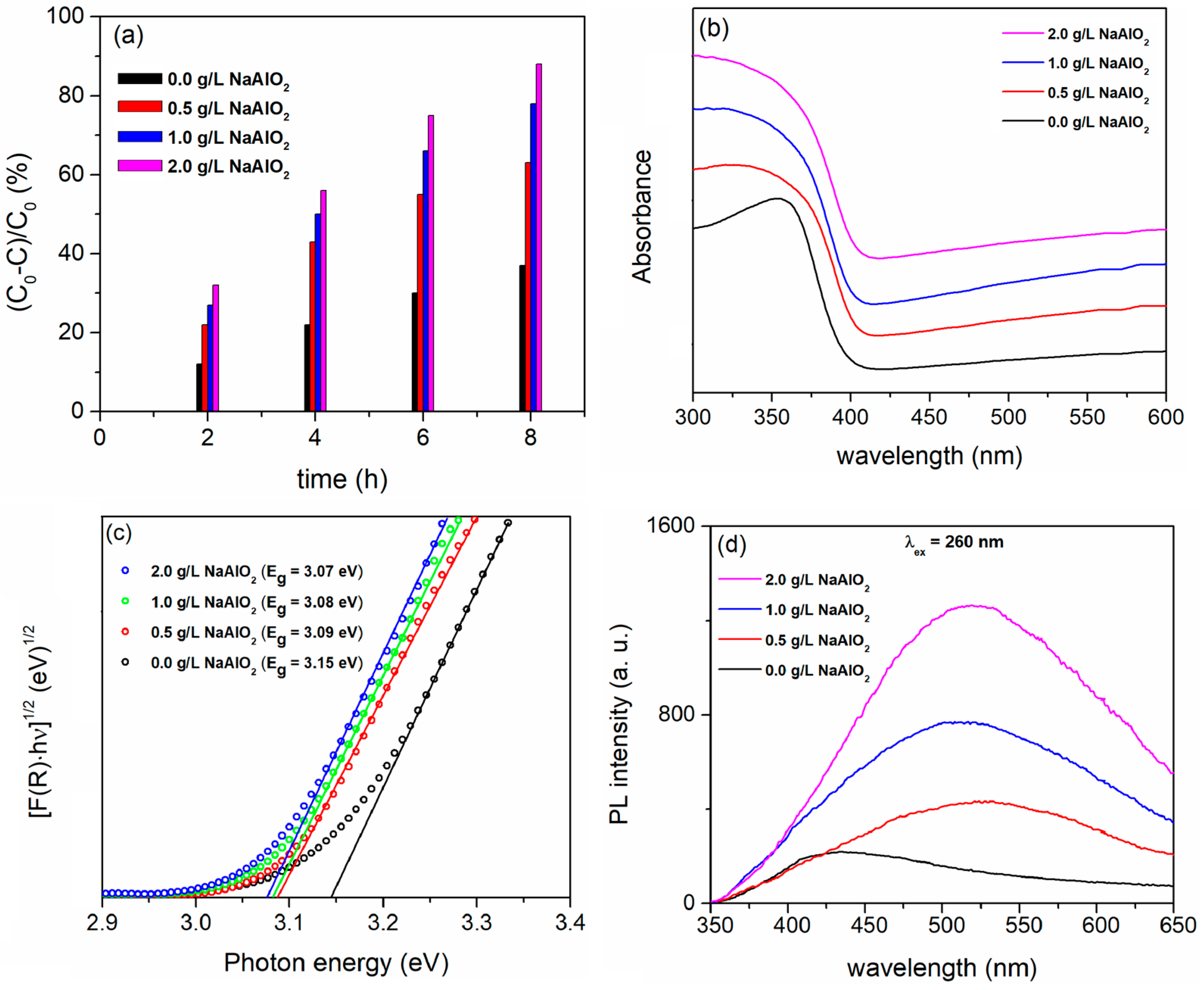
3.2.4. PA of TiO2/Al2TiO5 Coatings

Al2TiO5 is a pseudobrookite-type titanate with a wide band gap (~3.42 eV) and has been identified as a possible photocatalyst [92,93] and a suitable candidate for coupling with TiO2 [94,95]. PEO of titanium in BE with the addition of NaAlO2 is an effective method for the formation of TiO2/Al2TiO5 coatings [26]. Figure 9 shows the SEM micrographs, EDS composition, XRD patterns, and the content of crystalline phases in the coatings formed in BE with the addition of different concentrations of NaAlO2 for 10 min.
The micro-discharges become more intense with an increasing concentration of NaAlO2 in BE [26], resulting in a larger amount of molten oxidized metal being ejected from the micro-discharge channels onto the coating surface and rapidly solidifying in contact with the electrolyte (Figure 9a). As a result, the number and diameter of the pores on the coating surface decreases, and it becomes rougher. The chemical composition of the coatings contains Ti from the substrate and O, P, and Al from the electrolyte (Figure 9b). The content of Al increases with an increasing concentration of NaAlO2 in BE, while the content of Ti decreases. The coating obtained in the BE consists of anatase TiO2, but when NaAlO2 is added in the BE in addition to the anatase, the rutile phase of TiO2 (PDF Card No.: 9001681) and Al2TiO5 (PDF Card No.: 2206495) were observed in the coatings. Figure 9d presents the weight fraction of the individual phases, estimated using the reference intensity ratio (RIR).
Figure 10a illustrates that the PA of the coatings formed in BE with the added NaAO2 is superior to that of the anatase TiO2 coating formed in BE. The PA improves with an increasing NaAlO2 concentration, reaching its highest level by adding 2.0 g/L of NaAlO2.
Compared to the anatase TiO2 coating, TiO2/Al2TiO5 coatings show no noticeable shift in the absorption band edge toward the visible spectrum (Figure 10b). The estimated Eg ranges from 3.15 eV for anatase TiO2 to 3.07 eV for the TiO2/Al2TiO5 coating prepared in BE with the addition of 2.0 g/L NaAlO2 (Figure 10c). This shift is due to a change in the anatase/rutile phase ratio in the coatings (Figure 9d).
The exceptional PA of TiO2/Al2TiO5 is most likely attributed to the high concentration of various oxygen vacancies and other defects in the formed coatings, which facilitate the regulation of electron transfer between reactants and photocatalysts. These defects are closely associated with the active sites involved in the heterogeneous photocatalytic reactions [96]. Figure 10d displays the PL emission spectra of the coatings excited at 260 nm. The PL centers in anatase TiO2 are defect centers related to the oxygen vacancies in the coating, and the PL intensity is low [97]. Al2TiO5 coatings have formed a significant number of oxygen vacancies and other defects on the surface due to the strong micro-discharges in BE containing NaAlO2 [98]. Since oxygen vacancies and defects can bind photo-induced electrons, forming free or binding excitons, a PL signal is easily generated when the coatings are exposed to radiation. The PL intensity increases with the number of oxygen vacancies and defects in the coatings [88]. However, oxygen vacancies and defects act as trapping sites for photo-induced electrons during photocatalysis. This effectively prevents the recombination of photo-generated electron/hole pairs, which increases the PA of TiO2/Al2TiO5 coatings.

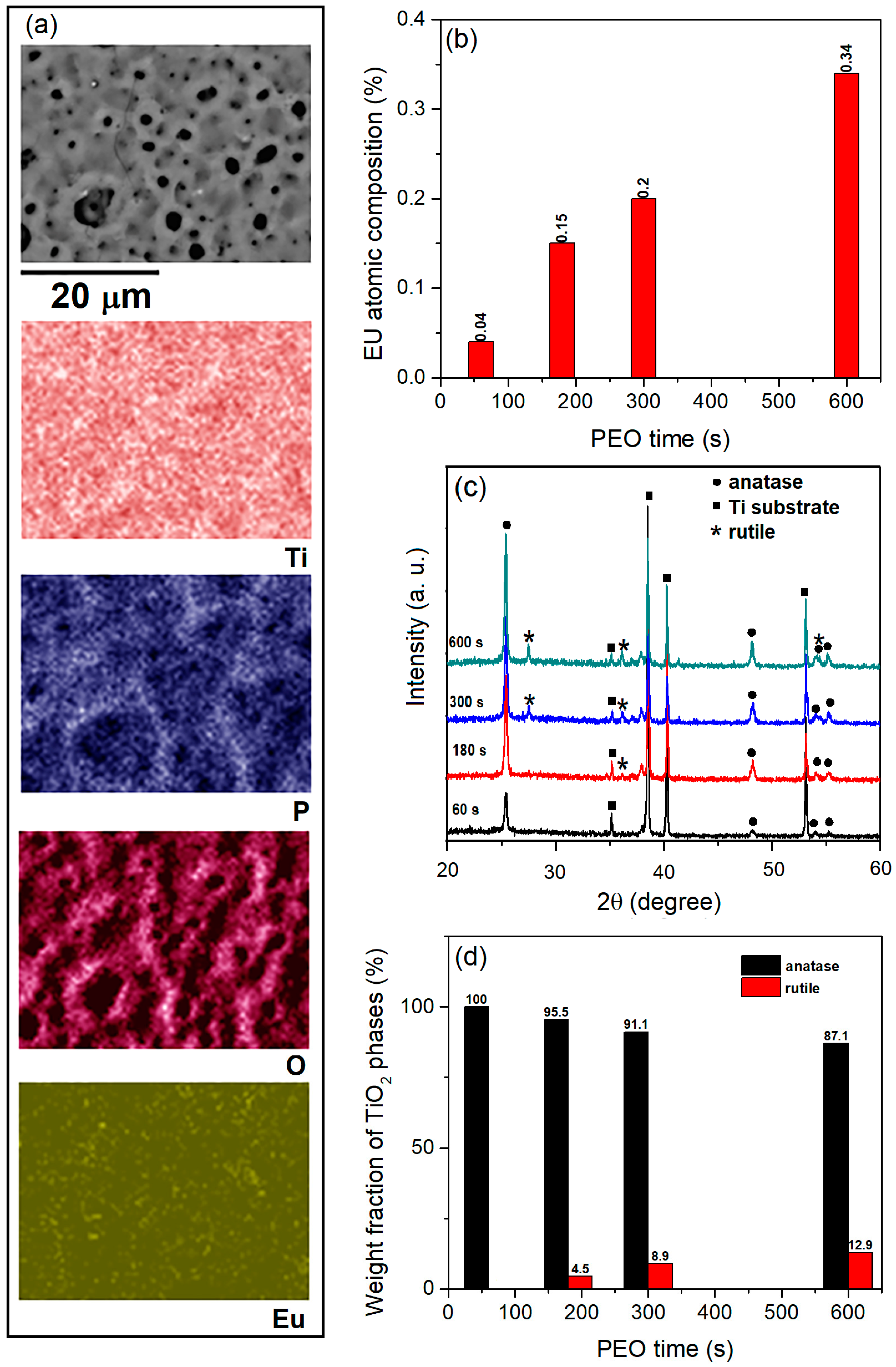
3.3. PA of TiO2 Coatings Doped with Rare Earth Ions

Doping TiO2 with rare earth (RE) ions is an effective method for enhancing its photocatalytic properties. A number of factors have been identified that contribute to the improved PA of RE-doped TiO2: (i) the recombination rate of photo-generated electron/hole pairs decreases due to the formation of oxygen vacancy charge trapping centers; (ii) the response of TiO2 is extended to the visible region; (iii) the conversion temperature from anatase to rutile is increased; and (iv) the pollutant interacts with the RE metals doped in TiO2 via f-orbitals, which increases the capacity to absorb the pollutant molecules and improves the PA [99,100,101,102].
In recent years, it has been shown that PEO on titanium in BE with the addition of RE oxide is a very practical way to form TiO2:RE3+ coatings for photocatalytic applications [21,40,43]. In this section, the results of PA for the TiO2:Eu3+ coatings formed in BE with the addition of 2 g/L of Eu2O3 particles for different PEO times will be presented. Similar results were obtained for the TiO2:Tb3+ and TiO2:Gd3+ coatings formed in BE with the addition of 2 g/L of Tb3O4 [40] and 2 g/L of Gd2O3 particles [21].
The TiO2:Eu3+ coatings formed in BE with the addition of Eu2O3 particles have a comparable morphology to the pure TiO2 coatings formed in BE (Figure 1a) [43]. The elements of the coatings are Ti, P, O, and Eu. All elements are uniformly distributed in the coatings (Figure 11a). The concentration of Eu is low and increases with the PEO time (Figure 11b). The XRD patterns of the TiO2:Eu3+ coatings formed after different PEO times are shown in Figure 11c. The coating formed for the 60 s consists of anatase TiO2, while the anatase phase transforms into the rutile phase about 180 s after the start of PEO.
Figure 11d shows the weight fractions of the anatase (WA) and rutile (WR) phases, calculated using Equations (13) and (14):
W R = I R 0.884 I A + I R
W A = 1 W R
where IA is the integrated intensity of the anatase peak (101) at a 2θ angle of 25.4°, and IR is the integrated intensity of the rutile peak (110) at a 2θ angle of 27.5o. The low concentration of uniformly distributed Eu2O3 particles in the TiO2 coatings or the substitution of Eu ions in the TiO2 crystal lattice could be the reason for the lack of visible peaks of Eu species in the XRD patterns.
The chemical state of Eu in TiO2 coatings can be analyzed using XPS (Figure 12) and PL (Figure 13). Figure 12a shows the high-resolution Eu 3d spectra of the Eu-doped TiO2 coatings formed after varying PEO times. The spectra display two peaks resulting from the spin-orbit splitting of the Eu 3d levels (3d5/2 and 3d3/2). The Eu3+ state is indicated by the Eu 3d5/2 peak, located at 1134.7 eV [103]. The spin-orbit components (2p3/2 and 2p1/2) of the Ti 2p XPS spectra for the TiO2 coating appear at 459.0 eV and 464.9 eV, respectively, and are attributed to the Ti4+ ions in TiO2 (Figure 12b). In contrast, the XPS peaks corresponding to the Ti 2p spin-orbit components are shifted by 0.2 eV towards higher binding energies in all TiO2:Eu3+ coatings. This shift in binding energy suggests the incorporation of Eu3+ into the TiO2 lattice and indicates an intermediate oxidation state of Ti.
Figure 13 shows the PL excitation and emission spectra of the TiO2:Eu3+ coatings formed after varying PEO times. In the PL excitation spectra monitored at 613 nm (5D07F2 transition of Eu3+) (Figure 13a), a broad band appears between 250 nm to 350 nm, peaking around 275 nm. Additionally, a series of sharp peaks in the 350 nm to 550 nm range are observed, which correspond to the direct excitation of the Eu3+ ground state 7F0 into higher levels of 4f-manifold [104]. The broad band is associated with the charge transfer state (CTB) of Eu3+, which arises from the electronic transition between the empty 4f orbital of Eu3+ ions (4f6) and the fully occupied 2p orbital of O2− ions (2p6) [105]. The most intense excitation bands assigned to 4f-4f transitions of Eu3+ are 7F05L6 at 393 nm and 7F05D2 at 463 nm. The PL emission spectra of the TiO2:Eu3+ coatings, excited at 275 nm (Figure 13b) and 393 nm (Figure 13c), display sharp emission bands in the orange-red spectral range between 560 nm and 720 nm. These bands correspond to the 4f-4f transition of Eu3+ from the excited level 5D0 to the lower levels 7FJ (J = 0, 1, 2, 3, and 4) [106]. The electric dipole transition 5D07F2, which is hypersensitive (to the local environment of the Eu3+ ion) and is only allowed when the Eu3+ ion occupies a site without an inversion center, is associated with the strongest PL peak at 613 nm [107]. In contrast, the magnetically allowed dipole 5D07F1 transitions at 591 nm and 596 nm are not affected by the symmetry of the site [107]. To measure the degree of distortion of the inversion symmetry of the local environment of the Eu3+ ions in the host matrix, a spectroscopic method involves calculating the ratio of the emission intensity between the 5D07F2 and 5D07F1 transitions, known as the asymmetric ratio—R.
The symmetry of the Eu3+ ions in the TiO2 coatings remains largely unchanged with varying Eu3+ concentrations, as evidenced by the R value, which shows only a slight increase with a longer PEO time (Figure 13d) [108]. High values of R indicate a highly asymmetric environment of Eu3+ ions in TiO2. The site symmetry of Ti4+ ions in the anatase lattice is D2d. According to the branching rules of 32-point groups, the substitution of Ti4+ by Eu3+ ions leads to the formation of oxygen vacancies and lattice distortion due to the significant disparity of ionic radii and charge imbalance between Ti4+ (68 pm) and Eu3+ (95 pm), which changes the site symmetry of Eu3+ ions from the exact D2d symmetry to a lower site symmetry [109].
Figure 14 presents the PA and DRS spectra of the TiO2 coatings formed for 600 s, as well as the TiO2:Eu3+ coatings created after varying PEO durations. Compared to pure TiO2, the PA of the TiO2:Eu3+ coatings is noticeably higher (Figure 14a). As the amount of incorporated Eu3+ increases, the absorption edge of the pure TiO2 progressively shifts from the ultraviolet to the visible spectrum. The redshift is attributed to a charge transfer between the f electrons of Eu3+ ions and the CB or VB of TiO2 [110]. While TiO2:Eu3+ coatings formed after longer PEO times broaden the spectral range for photocatalysis, the TiO2:Eu3+ coating formed after 60 s of PEO exhibits the best PA.
The TiO2:Eu3+ coating that forms after 60 s of PEO contains only the anatase phase of TiO2, which has a high degree of structural organization around the incorporated Eu3+ ions. The conversion of anatase to rutile by a prolonged PEO process time probably causes the distortion of the Eu3+ surrounding lattice (Figure 13d). The increase in R, the measure of the degree of distortion, also increases with the PEO time. This indicates that the Eu3+ ions, in this case, could serve as centers for the recombination of electron/hole pairs, suggesting that the Eu3+ environment is more important than the Eu3+ concentration for the photocatalytic application of TiO2:Eu3+ coatings.

3.4. PA of TiO2 Coatings Doped with Transition Metals

Doping of TiO2 with transition metals is often used to improve PA by shifting the absorption edge of TiO2 towards the visible light and preventing the recombination of photo-generated electron/hole pairs by creating new electron states within the electronic structure of TiO2 [111,112,113]. In recent years, there has been significant research on the synthesis of TiO2 coatings modified with various transition metals for photocatalytic applications [18,19,22,30,37,39,47]. The most common electrolytes used for the formation of such coatings contain acetate, nitrate, sulfate, and oxalate forms of transition metal salts. This section presents the results of PA for Mn-, Ni-, and Co-modified TiO2 coatings formed for 60 s in BE with the addition of MnO, NiO, and Co3O4 particles at different concentrations, respectively. TiO2:Fe [39], TiO2:V [47], and TiO2:Ag [22] photocatalysts for the degradation of MO can also be formed by PEO on titanium in BE with the addition of FeSO4, NH4VO3, and colloidal Ag nanoparticles, respectively.
Figure 15a shows the SEM micrographs of coatings formed in BE and in BE with the addition of MnO, NiO, or Co3O4 particles at the highest concentrations used. The addition of MnO, NiO, or Co3O4 particles to the BE does not significantly affect the morphology of the coatings formed. The EDS composition of the coatings in Figure 15a is shown in Figure 15b. The content of Mn, Ni, and Co detected in the coatings is low, especially for the coatings formed in BE with small amounts of MnO, NiO, or Co3O4 particles. The Ti/Mn, Ti/Ni, and Ti/Co ratios from the wavelength dispersive XRF measurements show that the Mn, Ni, and Co contents in the coatings increase with the concentration of MnO, NiO, and Co3O4 particles in BE, respectively (Figure 15d). As shown in the XRD patterns of the coatings in Figure 15a, the coatings are predominantly composed of the anatase phase of TiO2, with no indication of Mn-, Ni-, or Co-containing phases (Figure 15c).
High-resolution XPS spectra of the 2p region for the Mn, Ni, and Co-doped TiO2 coatings are shown in Figure 16. The Mn species are in the Mn2+ oxidation state, as evidenced by the two peaks in the Mn 2p XPS spectrum (Figure 16a) at approximately 653.4 eV and 641.6 eV, corresponding to Mn 2p1/2 and Mn 2p3/2, respectively [114]. The XPS spectrum of Ni 2p, shown in Figure 16b, reveals satellite peaks at 878.0 eV and 860.2 eV, with the Ni 2p1/2 and 2p3/2peaks located around 872.7 eV and 855.0 eV, respectively. These results confirm the presence of Ni2+ [115]. The Co 2p XPS spectrum (Figure 16c) shows Co 2p1/2 and Co 2p3/2 peaks at binding energies of about 795.4 eV and 779.5 eV, respectively. The satellite peaks, along with the position and spin-orbit splitting between the Co 2p1/2 and Co 2p3/2 peaks of 15.9 eV [116], suggest that Co is mainly in the Co2+ oxidation state.
Figure 17a illustrates the PA of the coatings formed in BE with varying concentrations of MnO, NiO, and Co3O4 particles. The concentrations of MnO, NiO, and Co3O4 particles significantly impact the PA of the coatings. In terms of PA, the Mn-, Ni- and Co-doped TiO2 coatings outperformed the pure TiO2 coatings, except for the coatings produced in BE by adding 3.0 g/L of NiO and 3.0 g/L of Co3O4 particles. The highest PA was observed in the coatings formed in BE with 0.75 g/L of MnO, 1.5 g/L of NiO, and 2.0 g/L of Co3O4 particles.
Since all formed anatase TiO2 coatings modified with Mn, Ni, and Co exhibit nearly identical morphologies, the observed PA can be attributed to the varying amounts of Mn, Ni, and Co in the coatings. These transition metals (Mn, Ni, and Co) enhance the PA primarily by either slowing down the fast recombination of photo-generated electron/hole pairs or by extending the optical absorption spectrum of the TiO2 coatings into the visible region.
Mn- and Ni-doped TiO2 coatings show no noticeable shift of the absorption band in the direction of visible light, as the Tauc plots of the coatings formed show (Figure 17b). In contrast, Co-doped TiO2 coatings show a slight shift in the absorption band, which is consistent with previous results [117]. These results indicate that the main function of the Mn, Ni, and Co in TiO2 coatings is to prevent the rapid recombination of photo-generated electron/hole pairs, which is in accordance with the PL measurement (Figure 17c). The PL intensity decreases with an increasing concentration of MnO, NiO, and Co3O4 particles in the BE. A decrease in PL intensity is associated with an increase in PA, indicating improved separation of electron/hole pairs when MnO, NiO, and Co3O4 are present in BE at concentrations of 0.75 g/L, 1.5 g/L, and 2.0 g/L, respectively. However, both PL intensity and PA decrease simultaneously as the concentrations of MnO, NiO, and Co3O4 in the BE are further increased. This is because the transition metal dopants act as capture centers for photo-induced electrons [88].

3.5. The Chemical and Physical Stability of TiO2-Based Photocatalysts

An important factor for the applicability of the photocatalyst is its chemical and physical stability, which determines the lifetime and operating costs of the catalyst. TiO2-based photocatalysts formed by PEO of titanium have high durability and stability [26,32,43]. In this section, the results of the TiO2:Fe photocatalyst stability tests are presented. The PA after 8 h of irradiation following ten consecutive runs with a TiO2:Fe coating formed for 120 s in BE with the addition of 2 g/L of FeSO4 is shown in Figure 18a. The sample was cleaned with water after each run, dried, and then used for the next catalytic cycle. The PA clearly did not decrease. The crystal structure (Figure 18b) and morphology (Figure 18c) also did not change after 10 runs, which proves that there is neither significant wear of the photocatalyst from the support nor poisoning of the catalyst.

4. Conclusions

In summary, this review focuses on introducing different strategies to enhance the photocatalytic activity (PA) of TiO2-based coatings formed on titanium substrate by the plasma electrolytic oxidation (PEO) process for the degradation of methyl orange (MO). Pure TiO2 coatings formed in BE (10 g/L Na3PO4·12H2O) have a PA that does not exceed 35% after 8 h of simulated solar irradiation. Coupling TiO2 with suitable semiconductors such as WO3, SnO2, CdS, Sb2O3, Bi2O3, and Al2TiO5 increases PA due to a reduction in the recombination rate of photo-generated electron/hole pairs. For each system, there is an optimal concentration of coupled semiconductors with TiO2. When their concentration in the formed coatings is high, they oppose the center for trapping photo-induced electrons, leading to a decrease in PA. The TiO2/Al2TiO5 coatings showed the best photocatalytic performance. The TiO2/Al2TiO5 coating formed for 600 s in BE + 2 g/L of NaAlO2 has a PA of about 90% after 8 h of irradiation. The TiO2/WO3 coatings formed for a very short time in WSiA also show very good PA. For example, the TiO2/WO3 coating formed for 30 s in WSiA has a PA of about 75%. All other systems (TiO2/SnO2, TiO2/CdS, TiO2/Sb2O3, and TiO2/Bi2O3) have a PA of less than 60% after 8 h of irradiation.
The TiO2 coatings doped with rare earth ions also have a higher PA than the pure TiO2 coatings. For the most photocatalytically active coatings, it is around 60% after 8 h of irradiation. The TiO2 coatings doped with transition metals (Mn, Ni, Co) also show similar photocatalytic performance, with the exception of the TiO2:Fe coating, which was formed for 120 s in BE with the addition of 2 g/L of FeSO4 and has a PA of about 78%. Incorporated ions of rare earths and transition metals in TiO2 coatings prevent the fast recombination of photo-generated electron/hole pairs.
TiO2-based photocatalysts can be formed by PEO in a very short time in environmentally compatible electrolytes on a titanium substrate. They exhibit excellent physical and chemical stability, which makes them good candidates for use in the continuous photocatalytic degradation of organic pollutants.
Due to the advantages of photocatalysts on solid substrates compared to photocatalysts in the form of particles and because PEO allows for the very easy incorporation of particles from the electrolyte into the formed coatings, future attempts should be made to incorporate photocatalytically active particles into the TiO2 coatings by PEO to further improve the photocatalytic performance and extend the activation range to the visible range.

Funding

This research was funded by the Ministry of Education, Science, and Technological Development of the Republic of Serbia (Grant 451-03-136/2025-03/200162).

Data Availability Statement

The data presented in this study are available on request from the corresponding author.

Conflicts of Interest

The author declares no conflicts of interest.

References

  1. Benkhaya, S.; M’rabet, S.; Harfi, A.E. Classifications, properties, recent synthesis and applications of azo dyes. Heliyon 2020, 6, e03271. [Google Scholar] [CrossRef] [PubMed]
  2. Chiu, Y.-H.; Chang, T.-F.M.; Chen, C.-Y.; Sone, M.; Hsu, Y.-J. Mechanistic insights into photodegradation of organic dyes using heterostructure photocatalysts. Catalysts 2019, 9, 430. [Google Scholar] [CrossRef]
  3. Lanjwani, M.F.; Tuzen, M.; Khuhawar, M.Y.; Saleh, T.A. Trends in photocatalytic degradation of organic dye pollutants using nanoparticles: A review. Inorg. Chem. Commun. 2024, 159, 111613. [Google Scholar] [CrossRef]
  4. Raub, A.A.M.; Bahru, R.; Mohamed, M.A.; Latif, R.; Haniff, M.A.S.M.; Simarani, K.; Yunas, J. Photocatalytic activity enhancement of nanostructured metal-oxides photocatalyst: A review. Nanotechnology 2024, 35, 242004. [Google Scholar] [CrossRef]
  5. Jabbar, Z.H.; Graimed, B.H.; Ammar, S.H.; Sabit, D.A.; Najim, A.A.; Radeef, A.Y.; Taher, A.G. The latest progress in the design and application of semiconductor photocatalysis systems for degradation of environmental pollutants in wastewater: Mechanism insight and theoretical calculations. Mater. Sci. Semicond. Process. 2024, 173, 108153. [Google Scholar] [CrossRef]
  6. Pelaez, M.; Nolan, N.T.; Pillai, S.C.; Seery, M.K.; Falaras, P.; Kontos, A.G.; Dunlop, P.S.M.; Hamilton, J.W.J.; Byrne, J.A.; O’Shea, K.; et al. A review on the visible light active titanium dioxide photocatalysts for environmental applications. Appl. Catal. B 2012, 125, 331–349. [Google Scholar] [CrossRef]
  7. Al-Mamun, M.R.; Kader, S.; Islam, M.S.; Khan, M.Z.H. Photocatalytic activity improvement and application of UV-TiO2 photocatalysis in textile wastewater treatment: A review. J. Environ. Chem. Eng. 2019, 7, 103248. [Google Scholar] [CrossRef]
  8. Kumar, S.G.; Devi, L.G. Review on modified TiO2 photocatalysis under UV/Visible light: Selected results and related mechanisms on interfacial charge carrier transfer dynamics. J. Phys. Chem. A 2012, 115, 13211–13241. [Google Scholar] [CrossRef] [PubMed]
  9. Guo, Q.; Zhou, C.; Ma, Z.; Yang, X. Fundamentals of TiO2 photocatalysis: Concepts, mechanisms, and challenges. Adv. Mater. 2019, 31, 1901997. [Google Scholar] [CrossRef]
  10. Etacheri, V.; Valentin, C.D.; Schneider, J.; Bahnemann, D.; Pillai, S.C. Visible-light activation of TiO2 photocatalysts: Advances in theory and experiments. J. Photochem. Photobiol. C 2015, 25, 1–29. [Google Scholar] [CrossRef]
  11. Schneider, J.; Matsuoka, M.; Takeuchi, M.; Zhang, J.; Horiuchi, Y.; Anpo, M.; Bahnemann, D.W. Understanding TiO2 photocatalysis: Mechanisms and materials. Chem. Rev. 2014, 114, 9919–9986. [Google Scholar] [CrossRef] [PubMed]
  12. Zhu, D.; Zhou, Q. Action and mechanism of semiconductor photocatalysis on degradation of organic pollutants in water treatment: A review. Environ. Nanotechnol. Monit. Manag. 2019, 12, 100255. [Google Scholar] [CrossRef]
  13. Basavarajappa, P.S.; Patil, S.B.; Ganganagappa, N.; Reddy, K.R.; Raghu, A.V.; Reddy, C.V. Recent progress in metal-doped TiO2, non-metal doped/codoped TiO2 and TiO2 nanostructured hybrids for enhanced photocatalysis. Int. J. Hydrogen Energy 2020, 45, 7764–7778. [Google Scholar] [CrossRef]
  14. Mikolajczyk, A.; Wyrzykowska, E.; Mazierski, P.; Grzyb, T.; Wei, Z.; Kowalska, E.; Caicedo, P.N.A.; Zaleska-Medynska, A.; Puzyn, T.; Nadolna, J. Visible-light photocatalytic activity of rare-earth-metal-doped TiO2: Experimental analysis and machine learning for virtual design. Appl. Catal. B 2024, 346, 123744. [Google Scholar] [CrossRef]
  15. Chen, D.; Cheng, Y.; Zhou, N.; Chen, P.; Wang, Y.; Li, K.; Huo, S.; Cheng, P.; Peng, P.; Zhang, R.; et al. Photocatalytic degradation of organic pollutants using TiO2-based photocatalysts: A review. J. Clean. Prod. 2020, 268, 121725. [Google Scholar] [CrossRef]
  16. Karbasi, M.; Chaharmahali, E.N.R.; Hosseini, R.; Giannakis, S.; Bahramian, H.; Kaseem, M.; Fattah-alhosseini, A. A review on plasma electrolytic oxidation coatings for organic pollutant degradation: How to prepare them and what to expect of them? J. Environ. Chem. Eng. 2023, 11, 110027. [Google Scholar] [CrossRef]
  17. Fattah-alhosseini, A.; Chaharmahali, R.; Kaseem, M. Exploring nanoparticle contributions to enhanced photocatalytic activity of PEO coatings on titanium: A review of the recent advancements. Nano-Struct. Nano-Objects 2024, 39, 101273. [Google Scholar] [CrossRef]
  18. Cai, N.; Mai, Y.; Su, R.; Lv, D. Synthesis of porous TiO2 and Fe-doped TiO2 films for photocatalysis by a cooling enhanced plasma electrolytic oxidation approach. Mater. Lett. 2024, 365, 136464. [Google Scholar] [CrossRef]
  19. Alizad, S.; Fattah-alhosseini, A.; Karbasi, M.; Chaharmahali, R. Exploring the impact of iron doping on the photocatalytic efficiency of TiO2 coatings produced on Ti via PEO. Ceram. Int. 2024, 50, 45083–45093. [Google Scholar] [CrossRef]
  20. Hosseini, R.; Fattah-alhosseini, A.; Karbasi, M.; Giannakis, S. Tailoring surface defects in plasma electrolytic oxidation (PEO) treated 2-D black TiO2: Post-treatment role, and intensification by peroxymonosulfate activation in visible light-driven photocatalysis. Appl. Catal. B 2024, 340, 123197. [Google Scholar] [CrossRef]
  21. Torres-Ceron, D.A.; Stojadinović, S.; Radić, N.; Amaya-Roncancio, S.; Velasquez-Tamayo, J.P.; Benavides-Palacios, V.; Restrepo-Parra, E. TiO2:Gd3+ coatings prepared at various PEO process times: Physical-chemical characterization, simulation, and photocatalytic activity. Appl. Surf. Sci. 2024, 665, 160351. [Google Scholar] [CrossRef]
  22. Radić, N.; Ilić, M.; Stojadinović, S.; Milić, J.; Avdalović, J.; Šaponjić, Z. Photocatalytically active Ag-doped TiO2 coatings developed by plasma electrolytic oxidation in the presence of colloidal Ag nanoparticles. J. Phys. Chem. Solids 2024, 188, 111918. [Google Scholar] [CrossRef]
  23. Bahramian, H.; Giannakis, S.; Fattah-alhosseini, A.; Karbasi, M. Synergy of Cu2+-Cu(OH)2-CuO with TiO2 coatings, fabricated via plasma electrolytic oxidation: Insights into the multifaceted mechanism governing visible light-driven photodegradation of tetracycline. Chem. Eng. J. 2023, 476, 146588. [Google Scholar] [CrossRef]
  24. Lukiyanchuk, I.V.; Vasilyeva, M.S.; Yarovaya, T.P.; Nedozorov, P.M.; Tkachev, V.V.; Ustinov, A.Y.; Budnikova, Y.B.; Parotkina, Y.A. Photoactive TiO2-V2O5-WO3 film composites immobilized in titanium phosphate matrix by plasma electrolytic oxidation. J. Photochem. Photobiol. A 2023, 445, 115047. [Google Scholar] [CrossRef]
  25. Chaharmahali, R.; Fattah-alhosseini, A.; Karbasi, M.; Giannakis, S.; Bahramian, H.; Oulego, P. A systematic study on modulation of plasma electrolytic oxidation parameters for optimizing photocatalytic coatings on titanium substrates. J. Alloys Compd. 2023, 963, 171234. [Google Scholar] [CrossRef]
  26. Stojadinović, S.; Radić, N.; Vasilić, R. High photocatalytic activity of TiO2/Al2TiO5 coatings obtained by plasma electrolytic oxidation of titanium. Mater. Lett. 2023, 338, 134069. [Google Scholar] [CrossRef]
  27. Vargas-Villanueva, S.; Velásquez-Tamayo, J.P.; Torres-Cerón, D.A.; Mercado, D.F.; Torres-Palma, R.A.; Riassetto, D.; Riva, J.S.; Amaya-Roncancio, S.; Castilla-Acevedo, S.F.; Restrepo-Parra, E. Impact of the duty cycle on the morphology and photocatalytic properties of S-TiO2 obtained by plasma electrolytic oxidation to treat real electroplating wastewater contaminated with Cr6+. J. Environ. Chem. Eng. 2023, 11, 110246. [Google Scholar] [CrossRef]
  28. Bahramian, H.; Fattah-alhosseini, A.; Karbasi, M. Development of porous ceramic coatings via the PEO process: The key role of CuO nanoparticles in methylene blue photodegradation under visible light illumination. Appl. Surf. Sci. Adv. 2023, 18, 100511. [Google Scholar] [CrossRef]
  29. Manojkumar, P.; Lokeshkumar, E.; Premchand, C.; Saikiran, A.; Rama Krishna, L.; Rameshbabu, N. Facile preparation of immobilised visible light active W–TiO2/rGO composite photocatalyst by plasma electrolytic oxidation process. Phys. B 2024, 631, 413680. [Google Scholar] [CrossRef]
  30. Stojadinović, S.; Radić, N.; Vasilić, R.; Tadić, N.; Tsanev, A. Photocatalytic degradation of methyl orange in the presence of transition metals (Mn, Ni, Co) modified TiO2 coatings formed by plasma electrolytic oxidation. Solid State Sci. 2022, 129, 106896. [Google Scholar] [CrossRef]
  31. Stojadinović, S.; Radić, N.; Vasilić, R.; Tadić, N. One-pot plasma electrolytic oxidation synthesis of TiO2/Sb2O3 coatings for photocatalysis. Mater. Lett. 2022, 309, 131404. [Google Scholar] [CrossRef]
  32. Stojadinović, S.; Radić, N.; Tadić, N.; Vasilić, R.; Tsanev, A. TiO2/Bi2O3 coatings formed by plasma electrolytic oxidation of titanium for photocatalytic applications. J. Mater. Sci.: Mater. Electron. 2022, 33, 4467–4481. [Google Scholar] [CrossRef]
  33. Orsetti, F.R.; Bukman, L.; Santo, J.S.; Nagay, B.E.; Rangela, E.C.; Cruz, N.C. Methylene blue and metformin photocatalytic activity of CeO2-Nb2O5 coatings is dependent on the treatment time of plasma electrolytic oxidation on titanium. Appl. Surf. Sci. Adv. 2021, 6, 100143. [Google Scholar] [CrossRef]
  34. Coto, M.; Knight, P.; Joshi, R.; Francis, R.; Kumar, R.V.; Troughton, S.C.; Clyne, T.W. Optimization of the microstructure of TiO2 photocatalytic surfaces created by plasma electrolytic oxidation of titanium substrates. Surf. Coat. Technol. 2021, 411, 127000. [Google Scholar] [CrossRef]
  35. Vasilyeva, M.S.; Lukiyanchuk, I.V.; Sergeev, A.A.; Ustinov, A.Y.; Sergeeva, K.A.; Kuryavyi, V.G. Ti/TiO2-CoWO4-Co3(PO4)2 composites: Plasma electrolytic synthesis, optoelectronic properties, and solar light-driven photocatalytic activity. J. Alloys Compd. 2021, 863, 158066. [Google Scholar] [CrossRef]
  36. Finčur, N.L.; Grujić-Brojčin, M.; Šćepanović, M.J.; Četojević-Simin, D.D.; Maletić, S.P.; Stojadinović, S.; Abramović, B.F. UV-driven removal of tricyclic antidepressive drug amitriptyline using TiO2 and TiO2/WO3 coatings. React. Kinet. Mech. Catal. 2021, 132, 1193–1209. [Google Scholar] [CrossRef]
  37. Manojkumar, P.; Lokeshkumar, E.; Saikiran, A.; Govardhanan, B.; Ashok, M.; Rameshbabu, N. Visible light photocatalytic activity of metal (Mo/V/W) doped porous TiO2 coating fabricated on Cp-Ti by plasma electrolytic oxidation. J. Alloys Compd. 2020, 825, 154092. [Google Scholar] [CrossRef]
  38. Stojadinović, S.; Tadić, N.; Radić, N.; Grbić, B.; Vasilić, R. CdS particles modified TiO2 coatings formed by plasma electrolytic oxidation with enhanced photocatalytic activity. Surf. Coat. Technol. 2018, 344, 528–533. [Google Scholar] [CrossRef]
  39. Stojadinović, S.; Radić, N.; Tadić, N.; Vasilić, R.; Stefanov, P.; Grbić, B. Influence of iron doping on photocatalytic activity of TiO2 coatings formed on titanium by plasma electrolytic oxidation. J. Mater. Sci. Mater. Electron. 2018, 29, 9427–9434. [Google Scholar] [CrossRef]
  40. Stojadinović, S.; Tadić, N.; Radić, N.; Grbić, B.; Vasilić, R. Effect of Tb3+ doping on the photocatalytic activity of TiO2 coatings formed by plasma electrolytic oxidation of titanium. Surf. Coat. Technol. 2018, 337, 279–289. [Google Scholar] [CrossRef]
  41. Stojadinović, S.; Tadić, N.; Radić, N.; Grbić, B.; Vasilić, R. TiO2/SnO2 photocatalyst formed by plasma electrolytic oxidation. Mater. Lett. 2017, 196, 292–295. [Google Scholar] [CrossRef]
  42. Dohčević-Mitrović, Z.; Stojadinović, S.; Lozzi, L.; Aškrabić, S.; Rosić, M.; Tomić, N.; Paunović, N.; Lazović, S.; Nikolić, M.G.; Santucci, S. WO3/TiO2 composite coatings: Structural, optical and photocatalytic properties. Mater. Res. Bull. 2016, 83, 217–224. [Google Scholar] [CrossRef]
  43. Stojadinović, S.; Radić, N.; Grbić, B.; Maletić, S.; Stefanov, P.; Pačevski, A.; Vasilić, R. Structural, photoluminescent and photocatalytic properties of TiO2:Eu3+ coatings formed by plasma electrolytic oxidation. Appl. Surf. Sci. 2016, 370, 218–228. [Google Scholar] [CrossRef]
  44. Vasilyeva, M.S.; Rudnev, V.S.; Zvereva, A.A.; Kilin, K.N.; Sergeev, A.A.; Sergeevaa, K.A.; Nepomnyaschiy, A.V.; Voznesenskiy, S.S.; Ustinov, A.Y. Characterization and photocatalytic activity of SiO2, FeOx coatings formed by plasma electrolytic oxidation of titanium. Surf. Coat. Technol. 2016, 307, 1310–1314. [Google Scholar] [CrossRef]
  45. Franz, S.; Perego, D.; Marchese, O.; Lucotti, A.; Bestetti, M. Photoactive TiO2 coatings obtained by plasma electrolytic oxidation in refrigerated electrolytes. Appl. Surf. Sci. 2016, 385, 498–505. [Google Scholar] [CrossRef]
  46. Petrović, S.; Stojadinović, S.; Rožić, L.; Radić, N.; Grbić, B.; Vasilić, R. Process modeling and analysis of plasma electrolytic oxidation of titanium for TiO2/WO3 thin film photocatalysts by response surface methodology. Surf. Coat. Technol. 2015, 269, 250–257. [Google Scholar] [CrossRef]
  47. Vasilić, R.; Stojadinović, S.; Radić, N.; Stefanov, P.; Dohčević-Mitrović, Z.; Grbić, B. One-step preparation and photocatalytic performance of vanadium doped TiO2 coatings. Mater. Chem. Phys. 2015, 151, 337–344. [Google Scholar] [CrossRef]
  48. Akatsu, T.; Yamada, Y.; Hoshikawa, Y.; Onoki, T.; Shinoda, Y.; Wakai, F. Multifunctional porous titanium oxide coating with apatite forming ability and photocatalytic activity on a titanium substrate formed by plasma electrolytic oxidation. Mater. Sci. Eng. C 2013, 33, 4871–4875. [Google Scholar] [CrossRef]
  49. Mirelman, L.K.; Curran, J.A.; Clyne, T.W. The production of anatase-rich photoactive coatings by plasma electrolytic oxidation. Surf. Coat. Technol. 2012, 207, 66–71. [Google Scholar] [CrossRef]
  50. Stojadinović, S.; Radić, N.; Vasilić, R.; Petković, M.; Stefanov, P.; Zeković, L.; Grbić, B. Photocatalytic properties of TiO2/WO3 coatings formed by plasma electrolytic oxidation of titanium in 12-tungstosilicic acid. Appl. Catal. B 2012, 126, 334–341. [Google Scholar] [CrossRef]
  51. He, J.; Luo, Q.; Cai, Q.Z.; Li, X.W.; Zhang, D.Q. Microstructure and photocatalytic properties of WO3/TiO2 composite films by plasma electrolytic oxidation. Mater. Chem. Phys. 2011, 129, 242–248. [Google Scholar] [CrossRef]
  52. Bayati, R.; Moshfegh, A.Z.; Golestani-Fard, F.; Molaei, R. (WO3)x-(TiO2)1−x nano-structured porous catalysts grown by micro-arcoxidation method: Characterization and formation mechanism. Mater. Chem. Phys. 2010, 124, 203–207. [Google Scholar] [CrossRef]
  53. Bayati, M.R.; Moshfegh, A.Z.; Golestani-Fard, F. In situ growth of vanadia-titania nano/micro-porous layers with enhanced photocatalytic performance by micro-arc oxidation. Electrochim. Acta 2021, 55, 3093–3102. [Google Scholar] [CrossRef]
  54. Bayati, M.R.; Golestani-Fard, F.Z.; Moshfegh, A. Visible photodecomposition of methylene blue over micro arc oxidized WO3-loaded TiO2 nano-porous layers. Appl. Catal. A 2010, 382, 322–331. [Google Scholar] [CrossRef]
  55. Stojadinović, S.; Tadić, N.; Radić, N.; Stojadinović, B.; Grbić, B.; Vasilić, R. Synthesis and characterization of Al2O3/ZnO coatings formed by plasma electrolytic oxidation. Surf. Coat. Technol. 2015, 276, 573–579. [Google Scholar] [CrossRef]
  56. He, J.; Cai, Q.Z.; Ji, Y.G.; Luo, H.H.; Li, D.J.; Yu, B. Influence of fluorine on the structure and photocatalytic activity of TiO2 film prepared in tungstate-electrolyte via micro-arc oxidation. J. Alloys Compd. 2009, 482, 476–481. [Google Scholar] [CrossRef]
  57. Safira, A.R.; Fattah-alhosseini, A.; Kaseem, M. Surface growth of novel MOFs on AZ31 Mg alloy coated via plasma electrolytic oxidation for enhanced corrosion protection and photocatalytic performance. J. Magnes. Alloys 2024, 12, 2413–2432. [Google Scholar] [CrossRef]
  58. Kaseem, M.; Alluhayb, A.H.; Thanaa, T.T.; Fattah-alhosseini, A.; Alkaseem, M. Enhancing the photocatalytic performance and chemical durability of AZ31 magnesium alloy by incorporating two types of nanoparticles through plasma electrolytic oxidation. J. Magnes. Alloys 2024, 12, 4521–4537. [Google Scholar] [CrossRef]
  59. Khan, M.A.; Safira, A.R.; Kaseem, M.; Fattah-alhosseini, A. Enhanced electrochemical and photocatalytic performance achieved through dual incorporation of SnO2 and WO3 nanoparticles into LDH layer fabricated on PEO-coated AZ31 Mg alloy. J. Magnes. Alloys 2024, 12, 1880–1898. [Google Scholar] [CrossRef]
  60. Stojadinović, S.; Radić, N. MgAl oxide coatings modified with CeO2 particles formed by plasma electrolytic oxidation of AZ31 magnesium alloy: Photoluminescent and photocatalytic properties. Metals 2024, 14, 366. [Google Scholar] [CrossRef]
  61. Kaseem, M.; Zehra, T.; Dikici, B.; Dafali, A.; Fattah-alhosseini, A. A novel dual-functional layer exhibiting exceptional protection and photocatalytic activity by organic functionalization of plasma electrolyzed layer. J. Magnes. Alloys 2023, 11, 1247–1263. [Google Scholar] [CrossRef]
  62. Mashtalyar, D.V.; Imshinetskiy, I.M.; Nadaraia, K.V.; Gnedenkov, A.S.; Suchkov, S.N.; Opra, D.P.; Pustovalov, E.V.; Yu Ustinov, A.; Sinebryukhov, S.L.; Gnedenkov, S.V. Effect of TiO2 nanoparticles on the photocatalytic properties of PEO coatings on Mg alloy. J. Magnes. Alloy. 2023, 11, 735–752. [Google Scholar] [CrossRef]
  63. Stojadinović, S.; Radić, N.; Vasilić, R. ZnO particles modified MgAl coatings with improved photocatalytic activity formed by plasma electrolytic oxidation of AZ31 magnesium alloy in aluminate electrolyte. Catalysts 2022, 12, 1503. [Google Scholar] [CrossRef]
  64. Stojadinović, S.; Radić, N.; Vasilić, R. Photoluminescent and photocatalytic properties of Eu3+-doped MgAl oxide coatings formed by plasma electrolytic oxidation of AZ31 magnesium alloy. Coatings 2022, 12, 1830. [Google Scholar] [CrossRef]
  65. Thanaa, T.T.; Aadil, M.; Askari, A.; Fattah-alhosseini, A.; Alkaseem, M.; Kaseem, M. Highly corrosion-resistant and photocatalytic hybrid coating on AZ31 Mg alloy via plasma electrolytic oxidation with organic-inorganic integration. J. Magnes. Alloys 2025, 13, 260–282. [Google Scholar] [CrossRef]
  66. Fattah-alhosseini, A.; Chaharmahali, R.; Alizad, S.; Babaei, K.; Stojadinović, S. A review on the revealed improved photocatalytic activity of PEO coatings applied on Al alloys. Nano-Struct. Nano-Objects 2024, 39, 101233. [Google Scholar] [CrossRef]
  67. Ignjatović, S.; Blawert, C.; Serdechnova, M.; Karpushenkov, S.; Damjanović, M.; Karlova, P.; Dovzhenko, G.; Wieland, D.C.F.; Zeller-Plumhoff, B.; Starykevich, M.; et al. The influence of in situ anatase particle addition on the formation and properties of multifunctional plasma electrolytic oxidation coatings on AA2024 aluminum alloy. Adv. Eng. Mater. 2021, 23, 2001527. [Google Scholar] [CrossRef]
  68. Ignjatović, S.; Blawert, C.; Serdechnova, M.; Karpushenkov, S.; Damjanović, M.; Karlova, P.; Wieland, D.C.F.; Starykevich, M.; Stojanović, S.; Damjanović-Vasilić, L.; et al. Formation of multi-functional TiO2 surfaces on AA2024 alloy using plasma electrolytic oxidation. Appl. Surf. Sci. 2021, 544, 148875. [Google Scholar] [CrossRef]
  69. Stojadinović, S.; Vasilić, R.; Radić, N.; Tadić, N.; Stefanov, P.; Grbić, B. The formation of tungsten doped Al2O3/ZnO coatings on aluminum by plasma electrolytic oxidation and their application in photocatalysis. Appl. Surf. Sci. 2016, 377, 37–43. [Google Scholar] [CrossRef]
  70. Tadić, N.; Stojadinović, S.; Radić, N.; Grbić, B.; Vasilić, R. Characterization and photocatalytic properties of tungsten doped TiO2 coatings on aluminum obtained by plasma electrolytic oxidation. Surf. Coat. Technol. 2016, 305, 192–199. [Google Scholar] [CrossRef]
  71. Bayati, M.R.; Zargar, H.; Molaei, R.; Golestani-Fard, F.; Kajbafvala, E.; Zanganeh, S. One step growth of WO3-loaded Al2O3 micro/nano-porous films by micro arc oxidation. Colloids Surf. A 2010, 355, 187–192. [Google Scholar] [CrossRef]
  72. Stojadinović, S.; Radić, N.; Vasilić, R. Application of micro-arc discharges during anodization of tantalum for synthesis of photocatalytic active Ta2O5 coatings. Micromachines 2023, 14, 701. [Google Scholar] [CrossRef]
  73. Stojadinović, S.; Radić, N.; Perković, M. Nb2O5 and AlNbO4 coatings formed by plasma electrolytic oxidation of niobium: Synthesis, characterization, and photocatalytic activity. J. Mater. Sci. Mater. Electron. 2024, 35, 410. [Google Scholar] [CrossRef]
  74. Stojadinović, S.; Radić, N.; Perković, M. Highly efficient ZrO2 photocatalysts in the presence of UV radiation synthesized in a very short time by plasma electrolytic oxidation of zirconium. Opt. Mater. 2023, 146, 114608. [Google Scholar] [CrossRef]
  75. Stojadinović, S.; Radić, N. Photocatalytic performance of ZnO and ZnO/Zn3(PO4)2 coatings formed by plasma electrolytic oxidation of zinc. Solid State Sci. 2024, 153, 107578. [Google Scholar] [CrossRef]
  76. Fattah-alhosseinia, A.; Karbasi, M.; Fardosi, A.; Kaseem, M. Optimization of electrolyte composition for enhanced photocatalytic performance of the ceramic coating produced on brass by plasma electrolytic oxidation. Ceram. Int. 2024, 50, 25822–25831. [Google Scholar] [CrossRef]
  77. Clyne, T.W.; Troughton, S.C. A review of recent work on discharge characteristics during plasma electrolytic oxidation of various metals. Int. Mater. Rev. 2019, 64, 127–162. [Google Scholar] [CrossRef]
  78. Kaseem, M.; Fatimah, S.; Nashrah, N.; Ko, Y.G. Recent progress in surface modification of metals coated by plasma electrolytic oxidation: Principle, structure, and performance. Prog. Mater. Sci. 2021, 117, 100735. [Google Scholar] [CrossRef]
  79. Simchen, F.; Sieber, M.; Kopp, A.; Lampke, T. Introduction to plasma electrolytic oxidation—An overview of the process and applications. Coatings 2020, 10, 628. [Google Scholar] [CrossRef]
  80. Ćirić, A.; Stojadinović, S. Photoluminescence of ZrO2:Gd3+ and ZrO2:Dy3+ coatings formed by the plasma electrolytic oxidation. J. Alloys Compd. 2020, 832, 154907. [Google Scholar] [CrossRef]
  81. Sundararajan, G.; Krishna, L.R. Mechanisms underlying the formation of thick alumina coatings through the MAO coating technology. Surf. Coat. Technol. 2003, 167, 269–277. [Google Scholar] [CrossRef]
  82. Aliofkhazraei, M.; Macdonald, D.D.; Matykina, E.; Parfenov, E.V.; Egorkin, V.S.; Curran, J.A.; Troughton, S.C.; Sinebryukhov, S.L.; Gnedenkov, S.V.; Lampke, T.; et al. Review of plasma electrolytic oxidation of titanium substrates: Mechanism, properties, applications and limitations. Appl. Surf. Sci. Adv. 2021, 5, 100121. [Google Scholar] [CrossRef]
  83. Landi, S., Jr.; Segundo, I.R.; Afonso, C.; Lima, O., Jr.; Costa, M.F.M.; Freitas, E.; Carneiro, J. Evaluation of band gap energy of TiO2 precipitated from titanium sulphate. Phys. B 2022, 639, 414008. [Google Scholar] [CrossRef]
  84. Yan, H.; Wang, X.; Yaon, M.; Yao, X. Band structure design of semiconductors for enhanced photocatalytic activity: The case of TiO2. Prog. Nat. Sci. 2013, 23, 402–407. [Google Scholar] [CrossRef]
  85. Rawal, S.B.; Bera, S.; Lee, D.; Jang, D.J.; Lee, W.I. Design of visible-light photocatalysts by coupling of narrow band gap semiconductors and TiO2: Effect of their relative energy band positions on the photocatalytic efficiency. Catal. Sci. Technol. 2013, 3, 1822–1830. [Google Scholar] [CrossRef]
  86. Sharifiyan, M.S.; Fattah-alhosseini, A.; Karbasi, M. Optimizing the hydrothermal post-treatment process for a TiO2/WO3 hybrid coating to enhance the photocatalytic degradation of methylene blue under visible light. Ceram. Int. 2023, 49, 35175–35185. [Google Scholar] [CrossRef]
  87. Sharifiyan, M.S.; Fattah-alhosseini, A.; Karbasi, M. Photocatalytic evaluation of hierarchical TiO2/WO3 hybrid coating created by PEO/hydrothermal method. Appl. Surf. Sci. Adv. 2023, 18, 100541. [Google Scholar] [CrossRef]
  88. Jing, L.; Qu, Y.; Wang, B.; Li, S.; Jiang, B.; Yang, L.; Fu, W.; Fu, H.; Sun, J. Review of photoluminescence performance of nano-sized semiconductor materials and its relationships with photocatalytic activity. Sol. Energy Mater. Sol. Cells 2006, 90, 1773–1787. [Google Scholar] [CrossRef]
  89. Guo, X.; Chen, C.; Song, W.; Wang, X.; Di, W.; Qin, W. CdS embedded TiO2 hybrid nanospheres for visible light photocatalysis. J. Mol. Catal. A Chem. 2014, 387, 1–6. [Google Scholar] [CrossRef]
  90. Su, C.; Shao, C.; Liu, Y. Electrospun nanofibers of TiO2/CdS heteroarchitectures with enhanced photocatalytic activity by visible light. J. Colloid Interface Sci. 2011, 359, 220–227. [Google Scholar] [CrossRef]
  91. Ilie, A.G.; Scarisoareanu, M.; Morjan, I.; Dutu, E.; Badiceanu, M.; Mihailescu, I. Principal component analysis of Raman spectra for TiO2 nanoparticle characterization. Appl. Surf. Sci. 2017, 417, 93–103. [Google Scholar] [CrossRef]
  92. Azarniya, A.; Soltaninejad, M.; Zekavat, M.; Bakhshandeh, F.; Hosseini, H.R.M.; Amutha, C.; Ramakrishna, S. Application of nanostructured aluminium titanate (Al2TiO5) photocatalyst for removal of organic pollutants from water: Influencing factors and kinetic study. Mater. Chem. Phys. 2020, 256, 123740. [Google Scholar] [CrossRef]
  93. Bakhshandeh, F.; Azarniya, A.; Hosseini, H.R.M.; Jafari, S. Are aluminium titanate-based nanostructures new photocatalytic materials? Possibilities and perspectives. J. Photochem. Photobiol. A 2018, 353, 316–324. [Google Scholar] [CrossRef]
  94. Trung, N.D.; Anh, H.C.; Tri, N.; Loc, L.C. Fabrication of TiO2/Al2TiO5 nanocomposite photocatalysts. Int. J. Nanotechnol. 2020, 17, 607–621. [Google Scholar] [CrossRef]
  95. Trung, N.D.; Tri, N.; Phuong, P.H.; Anh, H.C. Synthesis of highly active heterostructured Al2TiO5/TiO2 photocatalyst in a neutral medium. J. Nanomater. 2020, 2020, 6684791. [Google Scholar] [CrossRef]
  96. Wang, B.; Liu, J.; Yao, S.; Liu, F.; Li, Y.; He, J.; Lin, Z.; Huang, F.; Liu, C.; Wang, M. Vacancy engineering in nanostructured semiconductors for enhancing photocatalysis. J. Mater. Chem. A 2021, 9, 17143. [Google Scholar] [CrossRef]
  97. Pallotti, D.K.; Passoni, L.; Maddalena, P.; Fonzo, F.D.; Lettieri, S. Photoluminescence mechanisms in anatase and rutile TiO2. J. Phys. Chem. C 2017, 121, 9011–9021. [Google Scholar] [CrossRef]
  98. Hajihashemi, M.; Shamanian, M.; Ashrafizadeh, F. Oxygen vacancy-induced Al2TiO5-based multifunctional ceramic composites: Electrochemical and optical properties. J. Electroceram. 2022, 48, 169–182. [Google Scholar] [CrossRef]
  99. Mazierski, P.; Mikolajczyk, A.; Bajorowicz, B.; Malankowska, A.; Zaleska-Medynska, A.; Nadolna, J. The role of lanthanides in TiO2-based photocatalysis: A review. Appl. Catal. B 2018, 233, 301–317. [Google Scholar] [CrossRef]
  100. Reszczyńska, J.; Grzyb, T.; Sobczak, J.W.; Lisowski, W.; Gazda, M.; Ohtani, B.; Zaleska, A. Lanthanide co-doped TiO2: The effect of metal type and amount on surface properties and photocatalytic activity. Appl. Surf. Sci. 2014, 307, 333–345. [Google Scholar] [CrossRef]
  101. Tobaldi, D.M.; Pulla, R.C.; Skapin, A.S.; Seabra, M.P.; Labrinch, J.A. Visible light activated photocatalytic behaviour of rare earth modified commercial TiO2. Mater. Res. Bull. 2014, 50, 183–190. [Google Scholar] [CrossRef]
  102. Setiawati, E.; Kawano, K. Stabilization of anatase phase in the rare earth; Eu and Sm ion doped nanoparticle TiO2. J. Alloys Compd. 2008, 451, 293–296. [Google Scholar] [CrossRef]
  103. Kumar, S.; Prakash, R.; Choudhary, R.J.; Phase, D.M. Structural, XPS and magnetic studies of pulsed laser deposited Fe doped Eu2O3 thin film. Mater. Res. Bull. 2015, 70, 392–396. [Google Scholar] [CrossRef]
  104. Li, H.; Sheng, Y.; Zhao, H.; Song, Y.; Gao, F.; Huo, Q.; Zou, H. Facile synthesis and luminescent properties of TiO2:Eu3+ nanorods and spindle-shaped nanoparticles from titanate nanotubes precursors. Mater. Res. Bull. 2012, 47, 4322–4328. [Google Scholar] [CrossRef]
  105. Zeng, Q.G.; Zhang, Z.M.; Ding, Z.J.; Wang, Y.; Sheng, Y.Q. Strong photoluminescence emission of Eu:TiO2 nanotubes. Scr. Mater. 2007, 57, 897–900. [Google Scholar] [CrossRef]
  106. Moon, B.K.; Kwon, I.M.; Yang, H.K.; Seo, H.J.; Jeong, J.H.; Yi, S.S.; Kim, J.H. Spectroscopy of nanocrystalline TiO2:Eu3+ phosphors. Colloids Surf. A 2008, 313-314, 82–86. [Google Scholar] [CrossRef]
  107. Binnemans, K. Interpretation of europium (III) spectra. Coord. Chem. Rev. 2015, 295, 1–45. [Google Scholar] [CrossRef]
  108. Li, J.G.; Wang, X.; Watanabe, K.; Ishigaki, T. Phase structure and luminescence properties of Eu3+-doped TiO2 nanocrystals synthesized by Ar/O2 radio frequency thermal plasma oxidation of liquid precursor mists. J. Phys. Chem. B 2006, 110, 1121–1127. [Google Scholar] [CrossRef]
  109. Yan, M.; Zou, H.; Zhao, H.; Song, Y.; Zheng, K.; Sheng, Y.; Wang, G.; Huo, Q. Fabrication and photoluminescence properties of TiO2:Eu3+ microspheres with tunable structure from solid to core-shell. CrystEngComm 2014, 16, 9216–9223. [Google Scholar] [CrossRef]
  110. Xu, A.W.; Gao, Y.; Liu, H.Q. The preparation, characterization, and their photocatalytic activities of rare-earth-doped TiO2 nanoparticles. J. Catal. 2002, 207, 151–157. [Google Scholar] [CrossRef]
  111. Rauf, M.A.; Meetani, M.A.; Hisaindee, S. An overview on the photocatalytic degradation of azo dyes in the presence of TiO2 doped with selective transition metals. Desalination 2011, 276, 13–27. [Google Scholar] [CrossRef]
  112. Kernazhitsky, L.; Shymanovska, V.; Gavrilko, T.; Naumov, V.; Kshnyakin, V.; Khalyavka, T. A comparative study of optical absorption and photocatalytic properties of nanocrystalline single-phase anatase and rutile TiO2 doped with transition metal cations. J. Solid State Chem. 2013, 198, 511–519. [Google Scholar] [CrossRef]
  113. Pozan, G.S.; Isleyen, M.; Gokcen, S. Transition metal coated TiO2 nanoparticles: Synthesis, characterization and their photocatalytic activity. Appl. Catal. B 2013, 140–141, 537–545. [Google Scholar] [CrossRef]
  114. Huang, S.; Li, H.; Xu, G.; Liu, X.; Zhang, Q.; Yang, L.; Cao, J.; Wei, X. Porous N-doped carbon sheets wrapped MnO in 3D carbon networks as high-performance anode for Li-ion batteries. Electrochim. Acta 2020, 342, 136115. [Google Scholar] [CrossRef]
  115. Peck, M.A.; Langell, M.A. Comparison of nanoscaled and bulk NiO structural and environmental characteristics by XRD, XAFS, and XPS. Chem. Mater. 2012, 24, 4483–4490. [Google Scholar] [CrossRef]
  116. Fang, Z.; Xing, L.; Liu, Y.; Guo, X.; Qi, T.; Liu, J.; Wang, L. Ternary heterojunction stabilized photocatalyst of Co-TiO2/g-C3N4 in boosting sulfite oxidation during wet desulfurization. Appl. Surf. Sci. 2021, 551, 149478. [Google Scholar] [CrossRef]
  117. Madarász, D.; Pótári, G.; Sápi, A.; László, B.; Csudai, C.; Oszkó, A.; Kukovecz, Á.; Erdőhelyi, A.; Kónya, Z.; Kiss, J. Metal loading determines the stabilization pathway for Co2+ in titanate nanowires: Ion exchange vs. cluster formation. Phys. Chem. Chem. Phys. 2013, 15, 15917–15925. [Google Scholar] [CrossRef]
Figure 1. (a) Time variations of voltage and thickness, (b) SEM micrographs, and (c) XRD patterns of formed coatings during anodization of titanium in BE.
Reactions 06 00025 g001
Figure 2. (a) DRS spectra, (b) Tauc plots, (c) PA of TiO2 coatings at different PEO times, and (d) schematic representation of the mechanism of the photocatalytic reaction on TiO2.
Reactions 06 00025 g002
Figure 3. (a) SEM micrographs, (b) chemical composition, (c) XRD patterns, and (d) DRS spectra of formed coatings in WSiA at different PEO times.
Reactions 06 00025 g003
Figure 4. (a) PA, (b) PL of formed coatings in WSiA at different PEO times, and (c) schematic representation of the mechanism of the photocatalytic reaction on TiO2/WO3.
Reactions 06 00025 g004
Figure 5. (a) SEM micrographs, (b) XRD patterns, (c) Raman spectra, and (d) Cd/Ti ratio of formed coatings in BE with added CdS particles at different concentrations.
Reactions 06 00025 g005
Figure 6. (a) PA, (b) DRS spectra, and (c) Tauc plots of formed coatings in BE with added CdS particles at different concentrations. (d) Influence of CdS concentration in BE on PL intensity at 425 nm and PA after 8 h of irradiation of TiO2/CdS coatings.
Reactions 06 00025 g006
Figure 7. Schematic illustration of the photo-generated electron/hole transfer process in (a) TiO2/SnO2, (b) TiO2/Bi2O3, and (c) TiO2/Sb2O3.
Reactions 06 00025 g007
Figure 8. (a) PA, (b) DRS spectra, and (c) PL emission spectra excited at 350 nm of TiO2/SnO2, TiO2/Bi2O3, and TiO2/Sb2O3 coatings formed in BE with the addition of different concentrations of SnO2, Bi2O3, and Sb2O3 particles, respectively.
Reactions 06 00025 g008
Figure 9. (a) SEM micrographs, (b) chemical composition, (c) XRD patterns, and (d) crystalline phase content of formed coatings in BE with added NaAlO2 at different concentrations.
Reactions 06 00025 g009
Figure 10. (a) PA, (b) DRS spectra, (c) Tauc plots, and (d) PL emission spectra of formed coatings in BE with added NaAlO2 at different concentrations.
Reactions 06 00025 g010
Figure 11. (a) EDS maps of TiO2:Eu3+ coating formed for 600 s, (b) Eu atomic composition, (c) XRD patterns, and (d) weight fraction of anatase and rutile phases of formed coatings in BE + 2 g/L Eu2O3 particles.
Reactions 06 00025 g011
Figure 12. High-resolution XPS spectra: (a) Eu 3d; (b) Ti 2p.
Reactions 06 00025 g012
Figure 13. (a) PL excitation spectra monitored at 613 nm, (b) PL emission spectra excited at 275 nm, (c) PL emission spectra excited at 393 nm, and (d) the asymmetric ratio between 5D07F2 and 5D07F1.
Reactions 06 00025 g013
Figure 14. (a) PA and (b) DRS spectra of TiO2:Eu3+ coatings.
Reactions 06 00025 g014
Figure 15. (a) SEM micrographs; (b) chemical composition; (c) XRD patterns of coatings formed in (i) BE, (ii) BE + 1.5 g/L MnO, (iii) BE + 3.0 g/L NiO, and (iv) BE + 3.0 g/L Co3O4. (d) Mn/Ti, Ni/Ti, and Co/Ti ratios of formed coatings in BE with added MnO, NiO, and Co3O4 particles at different concentrations.
Reactions 06 00025 g015
Figure 16. (a) Mn 2p XPS spectrum of a coating formed in BE + 1.5 g/L MnO, (b) Ni 2p XPS spectrum of a coating formed in BE + 3.0 g/L NiO, and (c) Co 2p XPS spectrum of a coating formed in BE + 3.0 g/L Co3O4.
Reactions 06 00025 g016
Figure 17. (a) PA, (b) Tauc plots, and (c) PL emission spectra excited at 350 nm of Mn-, Ni-, and Co-doped TiO2 coatings formed in BE with the addition of different concentrations of MnO, NiO, or Co3O4 particles, respectively.
Reactions 06 00025 g017
Figure 18. (a) Recycling test of MO photodegradation, (b) XRD patterns before and after 10 cycles, and (c) SEM micrographs before and after 10 cycles.
Reactions 06 00025 g018
Disclaimer/Publisher’s Note: The statements, opinions and data contained in all publications are solely those of the individual author(s) and contributor(s) and not of MDPI and/or the editor(s). MDPI and/or the editor(s) disclaim responsibility for any injury to people or property resulting from any ideas, methods, instructions or products referred to in the content.

