Article

Overview of the Catalytic Liquefaction of Waste Plastics Process Development, Operation and Product Quality †

1
HiBD Laboratory Association, Fukuoka 808-0135, Japan
2
Institute of Environmental Science and Technology, Faculty of Environmental Engineering, The University of Kitakyushu, Fukuoka 808-0135, Japan
3
Research and Development Department, Environment Energy Co., Ltd., Fukuoka 808-0135, Japan
*
Author to whom correspondence should be addressed.
This is an extension of the conference paper presented at 11th ISFR2022, Pattaya, Thailand, 1 November 2022; special feature “Chemical Feedstock”.
Reactions 2024, 5(4), 740-752; https://doi.org/10.3390/reactions5040036
Submission received: 21 August 2024 / Revised: 27 September 2024 / Accepted: 2 October 2024 / Published: 4 October 2024

Abstract

:
Waste plastics were successfully decomposed with a solid acid catalyst to make oil. Spent FCC (Fluid Catalytic Cracking) catalyst was used for this process. The operation of this process was conducted in a horizontal agitated laboratory reactor with an inner volume of 1 L with 0.1 kg/h to the capacity of 80 kg/h of the demonstrate plant conducted by continuously feeding a plastic flake or molded cube to the heated powder catalyst bed at around 400–450 °C. The yield of oil was as high as 70 to 85%, depending on the type of plastic. The processing of a variety of waste plastics from home waste, industrial waste and even marine plastics could be processed to obtain oil with a low freezing point and a high heating value. The product was mainly composed of iso-paraffins, olefins and aromatics. The effective in situ dichlorination was attained from the waste plastic containing PVC. A small amount of PET in the plastic was converted to methyl benzene during the cracking operation.

1. Introduction

Plastic is an important material that is strong, durable and cheap. It is considered one of the most important products for human beings now. However, there is a common understanding that the waste quantities will substantially increase. Urbanization will create a measurable rise in the demand for plastic. In 2022, the amount of resin production, resin import, and domestic plastic consumption in Japan reached 9.6 million tons/year, while the waste plastic discharge was 8.2 million tons/year. Some of them have been recycled as it is called “bottle to bottle” or as feed stocks for the reformation (material recycling). However, most of the waste plastics have been burned off or in landfill [1].
Most of the waste is reused or recycled as a mechanical method (bottle to bottle), as solid fuel, or in landfills with other waste. The latter two methods harm wildlife, leach harmful chemicals, and emit greenhouse gases. Alternative energy development plan, aiming to boost a portion of alternative energy usage, has targeted boosting energy from waste production. It is not environmentally friendly to dispose of plastic waste by incineration or landfill, which leads to the emission of carbon dioxide and other greenhouse gases or water pollution even though the incineration can generate energy [2]. Since the most popular plastics, such as polyolefin, are produced from low olefins or aromatic hydrocarbons, making hydrocarbons from plastics is the real chemical recycling of plastics. However, the chemical recycling method to make high-quality fuel or chemicals by the degradation method has been extensively developed in the past 20–30 years but has not become popular yet [3].
Plastics → olefins (aromatics) → plastics
The Fluid Catalytic Cracking (FCC) process, where heavy petroleum fractions are converted into gasoline, olefins and others, is the most popular process in the oil refinery. The cracking catalyst, the key material of the FCC process, is a granule with a diameter of 50 µm, which contains zeolite such as Y-type zeolite in alumina matrix [4]. The spent FCC catalyst was discarded from the plant after being used repeatedly in the cycle of reaction and regeneration.
Authors have published several reports of the basic study on the catalytic cracking of polyolefins such as PE, PP and PS to clarify the cracking features of each plastic [5,6,7,8]. In this study, the development of a continuous cracking process for a variety of real-model polyolefins and waste plastics was conducted. In the process, waste plastics were directly charged into the powdered catalyst bed to be cracked and dechlorinated.

2. Basic Concept of Chemistry and Reaction Procedure FCC Catalyst

The physical route of the reaction of solid plastics on the solid FCC catalyst was shown in Figure 1. The flake of plastic that has been injected into the catalyst bed contacts the hot catalyst particle to accept energy and melt. The phenomenon of the melt is the same as that of a solid–liquid reaction catalyzed by an acid site [9]. The heat transfer characteristic from reactor wall to plastic is greatly enhanced by the contact with moving solid particles (catalyst).
The reaction network and reaction mechanism of plastics (polyolefins) on the acid site should be similar to that of paraffinic hydrocarbons [9,10], which will be described as the carbenium ion and secondary reactions shown in Equation (2) described below.
Reactions 05 00036 i001
The first step is the single clearage of the C–C bond in the polymer molecules to make lower molecule olefins, then the secondary reactions such as reversible structure isomerization and hydrogen transfer, which give aromatics and iso-paraffins [11].

3. Experimental Procedure

3.1. Reaction of Catalytic Cracking Procedure

The basic chemistry of the polyolefins with FCC catalyst is based on that of the catalytic reaction of petroleum hydrocarbons, whose essential intermediate is the carbenium ion [12]. Therefore, the performances of this process will be analyzed in comparison with those of the non-catalytic cracking process.
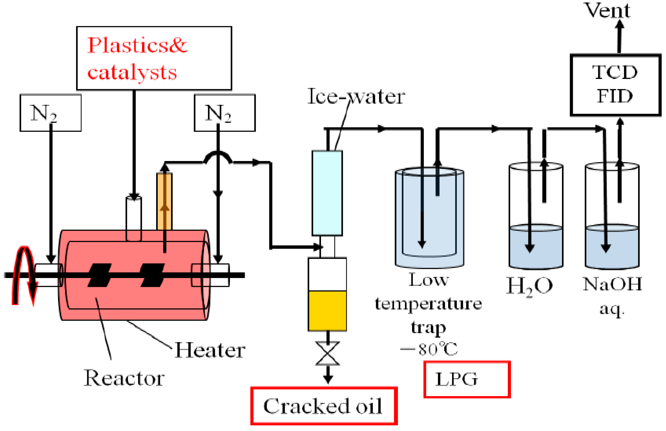
A continuous or batch-wise operation was conducted by using an agitated reactor as shown in Figure 2. The size of the reactor is 108 mmφ × 240 mm. Inside a horizontal agitating reactor, the spent FCC catalyst powder and Ca(OH)2 powder, a dechlorination agent, were first charged into the reactor and heated with an electric furnace. After the temperature of the catalyst bed reached the desired level of 410 °C to 450 °C, flake plastics were charged continuously with stirring. The reactor was operated either continuously or batch-wise.
The plastic surface is decomposed into small molecules, and some fraction of it is vaporized. The cracked products flowed out of the reactor accompanied by the carrier gas (N2 gas). They were cooled to condensed as liquid oil to be stored in a cylinder, while the uncondensed gas was deeply cooled by a low-temperature trap (−80 °C) to trap low-boiling product. Dry gas was passed through the water to catch HCl and then NaOH solution. The washed gas was subjected to GC analysis. The residual and trapped chloride were discharged from the reactor with the used catalyst mixture after operation of the plant was finished and cooled (at 50 °C or less). Hydrogen chloride generated from the chlorine-containing plastic is expected to be trapped by the dechlorinating agent (Ca(OH)2) charged together with the catalyst.
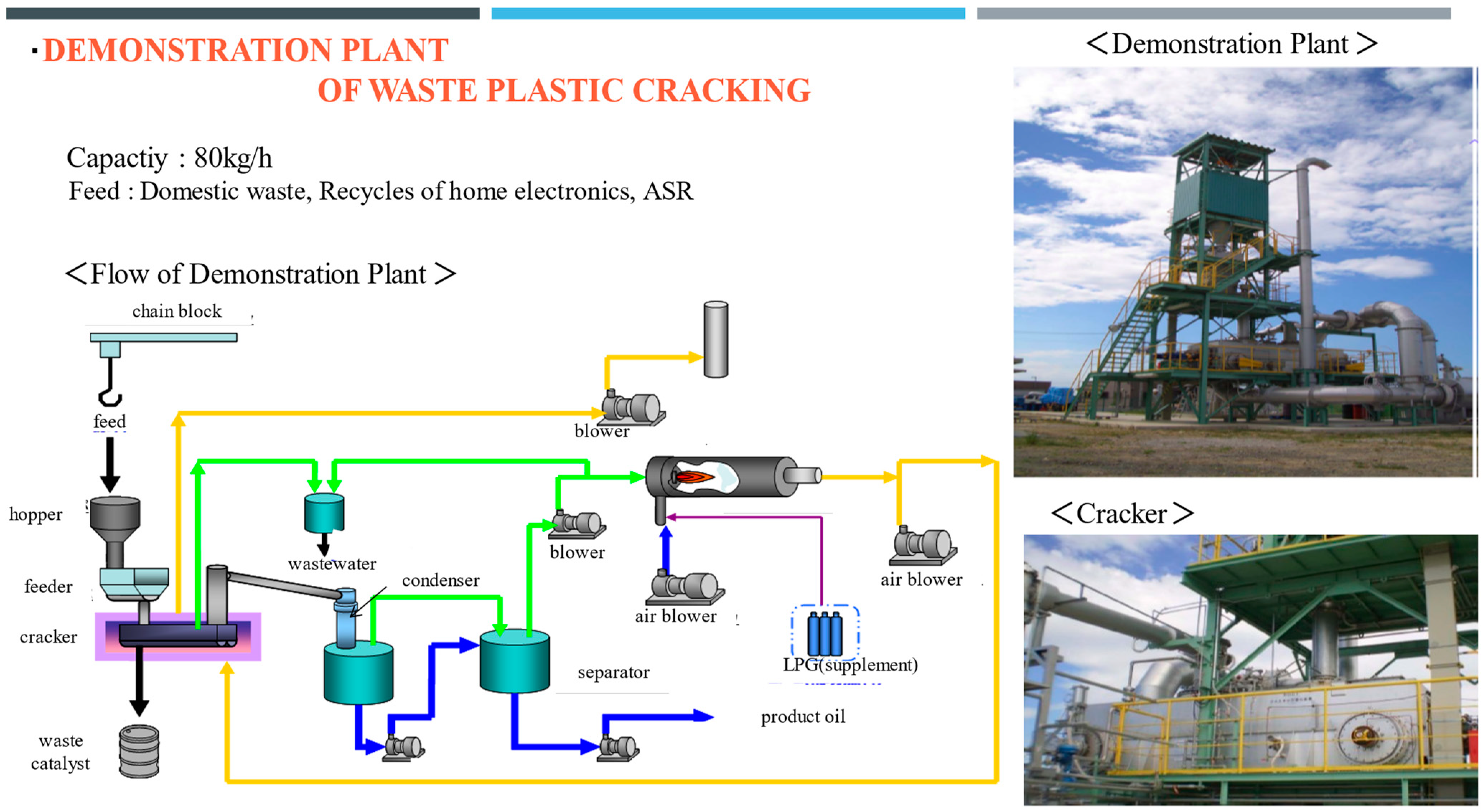
The process development was to scale up in a laboratory reactor, which has a processing capacity of 0.1 kg/h, to a small-scale bench plant (processing capacity of ~10 kg/h) as a basic design basis. A similar process is developed for a demonstration plant that can process 80 kg/h of general waste plastic. The process configuration and a picture are exhibited in Figure 3.

3.2. Procedure of the Demonstration Plant

A picture and diagram of a demonstration plant are shown in Figure 3. The reactor is a horizontal agitation type like the bench plant, and plastic flake is stored in the hopper located at the top of the plant. The raw material, RDF or other feed material, is put into the hopper after confirming that the input opening of the material receiving hopper is closed. The raw material is continuously fed from the receiving hopper to the top of the reactor with a screw feeder without heating. The reactor is heated with hot exhaust gas generated with a gas combustor, which has been set separately to the reactor. The feedstock is subjected to the reaction at the set temperature (400 °C to 450 °C) under atmospheric pressure. The raw material charged into the cracking unit agitated by the rotation of a two-axis paddle is homogeneously stirred installed in the furnace and is subjected to catalytic cracking by flowing at a high temperature for a fixed time under an atmosphere of dilute oxygen and is decomposed into gas and a residue. The cracked product produced flows out of the reactor in a gaseous state, cools with two coolers in series from about 450 °C to 40 °C to liquid, and the condensed liquid (oil) is retained in the oil tank. The cracked oil held in the cracked oil tank is then transferred to the dispensing tank by an oil pump. Non-condensable gases that have not been condensed in the oil coolers are sent to the gas fired burner for making hot gas.
The residue is chilled by circulating outside air (normal temperature) in a diluted air blower and an exhaustion gas inducement blower after the plastic liquefaction system has been shut down (raw material supply shutdown). The residue is discharged from the plastic liquefaction equipment after cooling is confirmed (at 50 °C or less).

3.3. Characterization of Products

The character of the liquid product was determined with GC-FID with a capillary column, Distillation GC and GC-MS. Other characteristics of liquids, such as density was determined by following the method of Japanese Industrial Standard JIS K 2249-1 [13], viscosity was determined by the method of Japanese Industrial Standard JIS K 2283 [14]. Hydrogen chloride (HCl), which was generated during the cracking of waste plastics and came out of the reactor as gas, was trapped in the aqueous NaOH solution and determined with an ion meter. The content of organic chlorine is decided following JIS. Analysis of deposited carbon on the catalyst was carried out using the TG-DTA method.

4. Results and Discussion

4.1. Catalytic and Non-Catalytic Cracking of Polyethylene (High Density PE)

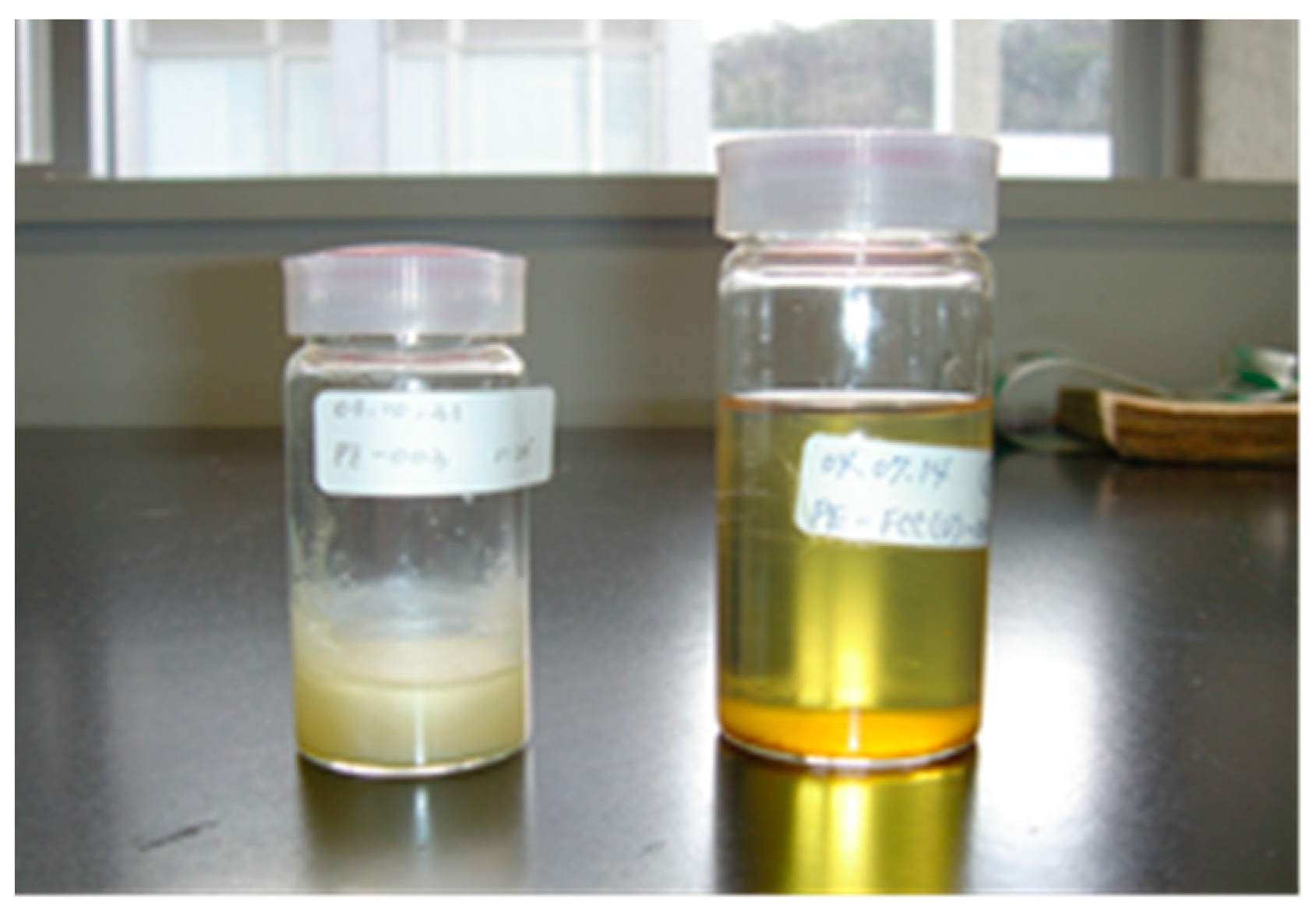
In order to clarify the catalytic performances of the spent FCC catalyst, the cracking reaction was conducted in comparison with the non-catalytic cracking (with sea sand powder) operated. Results are shown in Figure 4 and Table 1 and Table 2. As an example of using FCC spent catalyst, the cracking results of PE, which has been considered the most difficult to decompose among the main components of waste plastics in the conventional method.
As shown in Figure 4, without the spent FCC catalyst, the cracked oil contained was solid at room temperature, but with the catalyst, the cracked oil was a pale-yellow transparent liquid with little wax.
The material balance is summarized in Table 1. It is clear that the carbon number of the product heavy oil was smaller than that of the non-catalyst system. Moreover, LPG, naphtha, and kerosene contents increased. There was almost no residual and no carbonization.
Table 2 shows the quality of the product. From these results, it can be seen that in the non-catalyst system, most of the products were linear products such as paraffins and olefins, whereas by using the spent FCC catalyst, the products were diversified, with an increase in iso-paraffins and aromatics.
It is clear that by using the spent FCC catalyst, we succeeded in lowering the reaction temperature, reducing carbonization, diversifying the products to lower molecular weight, and reducing the wax content in the cracked oil even when the chemical structure of the feed is linear. It should be attributed to its acid function, as pointed out in Section 2.
As mentioned above, the chemical mechanism of the spent FCC catalyst should be explained by following the catalytic reaction involved in the FCC process. When using spent FCC catalyst, cracking is thought to occur through an ionic mechanism. FCC catalyst is an acid catalyst that contains zeolite. First, cracking occurs when carbenium ions form on the acid catalyst. These carbenium ions are in equilibrium with various structures, but the tertiary structure is the most stable, so most carbenium ions have this structure. These carbenium ions are isomerized, go through intermediates, and repeatedly decompose. When H is obtained in the form of carbenium ions, the structure is isomerized without decomposition. When a large amount of carbenium ions or olefins are included, the product is aromatized. It is predicted that the product will be more branched, which is consistent with the results. Also, because the branched and aromatic products are more abundant, it is less likely to crystalize, and a stable liquid oil is formed. The reaction to generate carbenium ions occurs at a lower temperature than the free radical reaction, making it possible to crack at low temperatures [15,16]. In the case of a non-catalyzed system, the skeletal isomerization is more difficult because of the character of the intermediate (free radical). It is possible that the chain transfer of the free radical reaction inside the large molecule makes a large primary product with a strait chain [5].

4.2. Catalytic Cracking of a Variety of Recycled Plastics

In a small bench plant, many types of waste plastic have been successfully processed to give oil. It proved that the catalytic process can be applied to a wide range of recycled plastics. In this section, we show the results on the processing of RDF (Residue-Derived Fuel). The composition is shown in Table 3. Other samples were the insulator of electric wire (Cross-Linked PE) and the film for huge commercial plastic bag plastic (Linear Low-Density PE + PB).
Operation conditions and results are shown in Table 4. The composition of the product oil and the PONA analysis data are shown in Table 5 and Table 6. The characteristic features and the reactivity and product yield are summarized as follows.
  • The main product is Oil (naphtha, kerosene and gas oil) ~60 wt%, LPG: 5~20 wt%
  • The oil yield and residue yield are highest for RDF, whose values are nearly 70 wt% and 11 wt%, respectively. On the other hand, PE (LLDPE) gives lower oil yield (60–65 wt%) and residue yield (5 wt%).
  • The yield of light hydrocarbons such as LPG and naphtha is much higher for LLDPE
  • The yield of residue, in another word coke, is highest for RDF (11 wt%) and lowest for LLDPE (4 wt%).
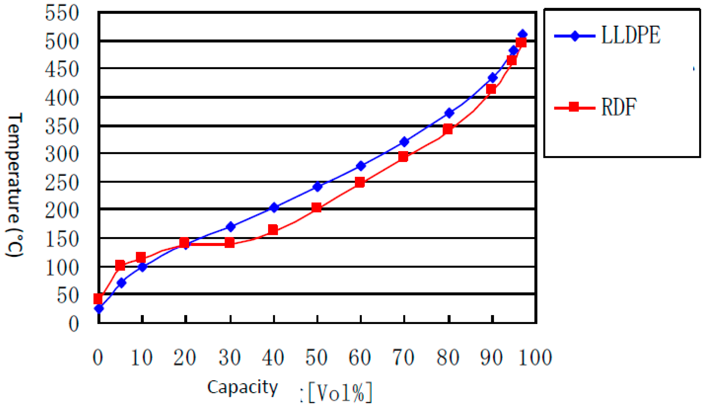
  • The distillation curve of oil as shown in Figure 5. shows similar trend for oil from LLDPE, and RDF with slight difference at around 150 °C.
  • PET, which commonly exists with low content in the waste plastic exhibits bad effect after being converted to terephthalic acid (TPA). In the present catalytic system PET is converted to methyl benzenes.

4.3. Cracking Performance of RDF Containing PVC and PET

Performance of Cracking Reaction on Sand
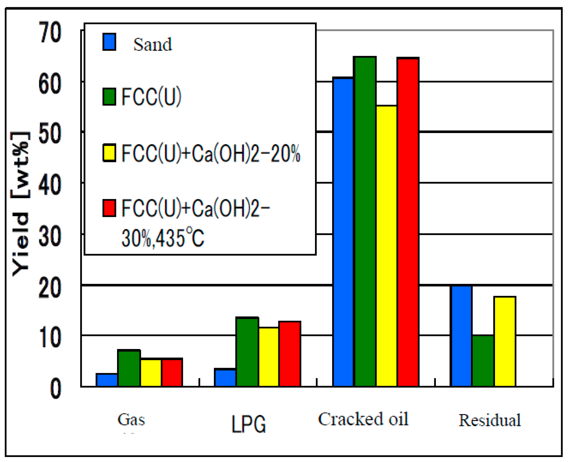
Although natural sand gave a similar level of oil yield to that of the FCC(U) system (60–65 wt%), as shown in Figure 6, the non-catalyzed process gave a much higher yield of residual (coke and heavy oil). Also, the outer surface of the natural sand was heavily covered by carbonaceous deposits. Sand showed little activity of chloride removal in oil. Finally, it lost fluidity.
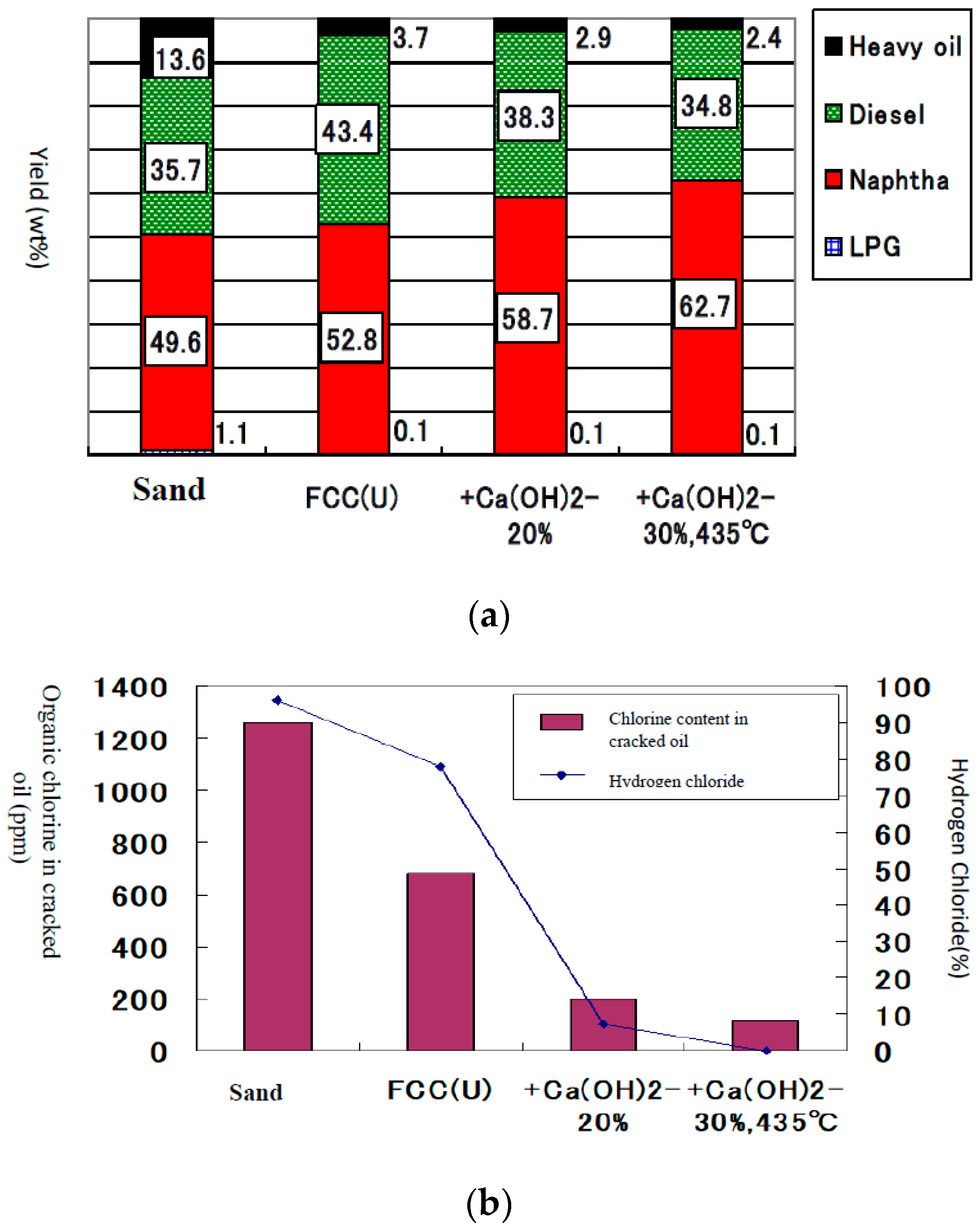
Figure 7a,b show the results of the cracking of the RDF, with the composition shown in Table 3, and formulated to cylindrical with a diameter of 8 mm and 10 mm. The catalyst is (1) natural sand at 435 °C (2) spent FCC(U), (3) spent FCC(U) + 20 wt% Ca(OH)2, (4) spent FCC(U) + 30 wt% Ca(OH)2 at 435 °C.
Another important feature is the behavior of chlorine in waste plastics. PVC easily loses chlorine atoms as HCl either in the catalyzed or in the non-catalyzed system. The concentration of organic Cl and free HCl emission of the catalyzed and Ca(OH)2 system was markedly suppressed. Ca(OH)2 traps HCl quickly after its generation. The promoted dehydrochlorination from PVC by solid acid makes low content of organic chlorine (<100 ppm) and retards the HCl emission.
Figure 7b shows the dependencies of organic chlorine content in oil and HCl emission as the process with the catalyst containing 20% Ca(OH)2 content. When only sand without spent FCC catalyst and Ca(OH)2 was used in the process, the content of organic chlorine jumped from 50 ppm to 1400 ppm. However, when the feed of Ca(OH)2 (20 wt%) started with RDF feed, the level of organic chlorine dropped to around 100 ppm.
The catalyst whose initial material was catalyst and Ca(OH)2 contained fairly large amounts of CaCl2 and CaCl(OH) after use. It shows HCl generated by the decomposition of PVC reacts quickly with added Ca(OH)2 to be fixed. The reaction of HCl should be shown as follows:
Ca(OH)2+ HCl → CaCl(OH) + H2O
CaCl(OH) + HCl → CaCl2 + H2O

4.4. Deposition of Coke in the Catalyst, Catalytic Activity and Its Recovery

In the FCC process, heavy petroleum feedstock is converted to light oil, mainly naphtha, but at the same time, a carbonaceous substance called coke deposition on the catalyst deteriorates its activity. Although carbon deposition was detected neither on the reactor wall nor the outer surface of the catalyst after the procession of RDF, the used catalyst gained weight by about 50 wt% or higher. This means that carbonaceous material was formed inside of the catalyst. The amount of coke reached about 50 wt% by processing 20 times of waste plastics. The used catalyst was subjected to the air treatment in situ at around 500 °C for 6 h (one night). The catalyst changed its color from black to pale grey. The TGA analysis shows that the weight loss decreased from about 50 wt% to 2 wt%. In fact, the used catalyst showed a similar level of activity to that of the virgin spent FCC catalyst after the in-situ air treatment at 500 °C for 6 h.

4.5. Results of Continuous Operation of the Demonstration Plant

A demonstration plant was operated to process waste plastics using real spent FCC catalyst generated in a refinery in Japan and Ca(OH)2. The reaction condition of the plant is shown in Table 7. Despite the large difference in the physical scale, the time factor of its operation was quite similar to that of the laboratory reactor. Both could be operated continuously for longer than 40 h without major trouble.
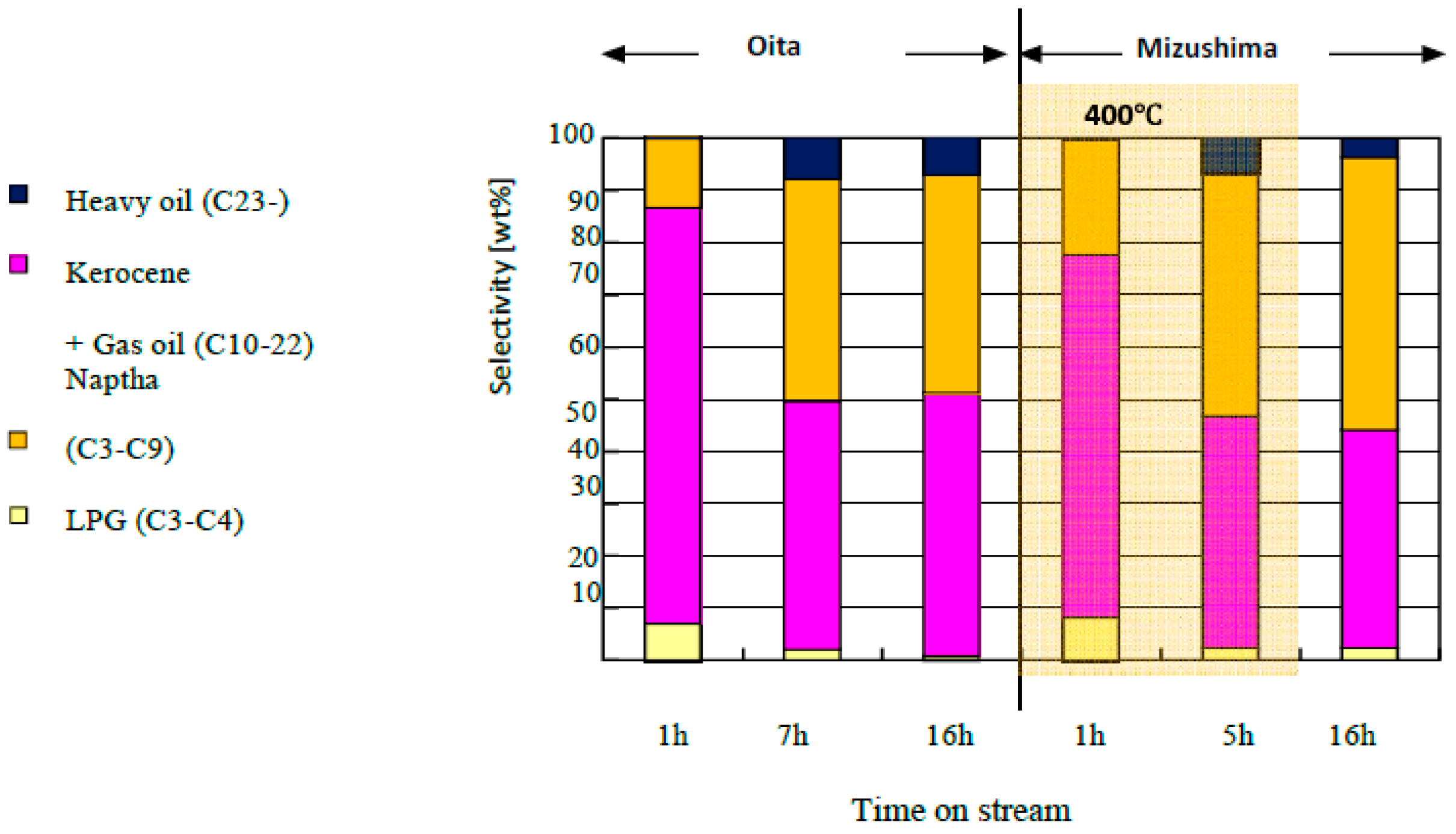
Results of the plant operation are shown in Table 8. Typical feedstocks MR(2) were the raw material for making the feed-to-material recycle process, whose composition was similar to that of RDF and whose shape is shown in Figure 8. The material MR(1) was prepared by removing PS and PVC from MR(2). Its composition is almost PE and PP. The time response of the comparative study was conducted in a laboratory reactor and demonstration plant. Although the oil composition was rich in middle distillate, as shown in Figure 9, after several hours of operation, the oil composition became quite like that of a laboratory plant to keep it for a long time while a comparative study was conducted on the activity of the Oita FCC waste catalyst and the Mizushima FCC waste catalyst.
Many data on the performances of both the laboratory and demonstration plant are summarized in Table 8 on the catalytic reaction on three types of real waste plastic. It is clear that for any feed, the oil yield is higher than 50 wt%. The data in Table 8 show the performance of the demonstration plant is quite like that of the laboratory plant.
Even ASR, the shredder dust generated from the recycling treatment of cars, gives oil, even though it contains many materials that are never converted to oil. Although the content of Cl is lower than 100 ppm, the content of nitrogen, especially in the oil from ASR, shows a very high value of basic nitrogen. It should be attributed to polyurethane or polyacrylonitrile (PAN); this problem should be solved by other methods than catalytic cracking.
As can be seen from Table 8, reference data from a small laboratory bench plant that were carried out by using the same catalyst and the same raw material (RDF) is also shown. As a matter of course, the oil yield and its physical properties vary greatly depending on the raw material waste plastic, but the oil yield is sufficiently high at 60–70 wt%. The data from Table 8 show good agreement with the lab bench plant data and are not dependent on the plant size. The oil, consisting of monocyclic aromatics, mainly ethylbenzene, probably produced from PS. All of these can be used as raw materials for chemicals or high-grade fuels. As described above, it has been demonstrated that our technology can be fully put to practical use.
Other demonstration plants and/or commercial plants whose processing capacities are 100~300 kg/h are vertically agitated ones and have been constructed and operated by two groups [17,18]. More detailed information will be described in the latter part of this report.
The structure of the reactor is a vertically agitated reactor for the demonstration plant reactor. The reason for it is mainly to reduce the depth of the catalyst bed, which makes the short residence period of the cracked product. Secondly, it makes it possible to ensure the contact between the injected plastic sample and catalyst powder. The third reason is to achieve a uniform temperature profile inside the reactor and scratch off the deposited coke on the reactor surface.
Noda et al. [17] have constructed a commercial plant and demonstration plant of catalytic cracking of waste plastic and tested many kinds of samples, such as degraded plastic structures, household electric items or shredder dust from car recycling, by applying our technology, which is called HICOP technology. The HICOP-200 is the first practical waste plastic oil production system that uses a catalytic cracking method. This makes it possible to produce the high-quality oil that is not possible with pyrolysis technology, and it is expected to lead to a shift from conventional thermal recycling, which ends with incineration, to chemical recycling, which has a wide range of uses, including automobile fuel and plastic raw materials.
Idemitsu Kosan Co., Ltd. (Chiba, Japan) and Environment Energy Co., Ltd. (Hiroshima, Japan) have been collaborating on the development of waste plastics liquefaction technology since FY2019 as the project of the “Carbon dioxide emission control measures project cost subsidy” by the Ministry of the Environment, Government of Japan. For this demonstration study, the plastic liquefaction plant (HiCOP method) has been constructed in the Chiba Complex of Idemitsu, which is the nation’s first demonstration of this kind [18]. HiCOP technology, a catalytic cracking method, is a patented technology invented by the author (Kaoru Fujimoto), the head of HiBD Research Institute. Now they have reached the prospect of developing the technology necessary for the construction of commercial facilities, they will carry out the basic design for the start of commercial operation of 20,000 tons/year of used plastics in FY2025 [19].

5. Conclusions

Continuous liquefaction of waste plastics was successfully conducted by using a horizontal agitating reactor that used spent FCC catalyst. The product was oil, which is rich in naphtha and middle distillate. The process is quite simple, where the plastic waste is introduced to the heated catalyst bed. The method does not require pretreatment. Polyethylene, which is rather difficult to decompose, was easily liquified to obtain an aromatic rich hydrocarbon. Even from the PVC-containing plastics, a chlorine-free oil was obtained.
Several demonstration plants and a commercial plant have been operating to obtain oils suitable for fuel as well as chemical feedstock.

Author Contributions

K.F.: conceptualization, methodology, project administration, writhing—review and editing. J.S.: formal analysis, investigation, writing original draft preparation, writing—review and editing. H.T.: formal analysis, investigation, data curation, resources. All authors have read and agreed to the published version of the manuscript.

Funding

This research received no external funding.

Data Availability Statement

The data presented in this study are available on request from the corresponding author.

Conflicts of Interest

Haruki Tani is affiliated with Environment Energy Co., Ltd., Fukuoka. The remaining authors declare that the research was conducted in the absence of any commercial or financial relationships that could be construed as a potential conflict of interest.

References

  1. Plastic Management Institute. An Introduction to Plastic Recycling Plastic Waste in Japan. 2022. Available online: http://www.pwmi.or.jp/ei/index.htm (accessed on 22 April 2022).
  2. Deutsche Gesellschaft für Internationale Zusammenarbeit (GIZ) GmbH. Waste to Energy Management Options in Municipal Solid Waste Management; Deutsche Gesellschaft für Internationale Zusammenarbeit (GIZ) GmbH: Eschborn, Germany, 2017. [Google Scholar]
  3. Buekens, A.G.; Huang, H. Catalytic Plastics Cracking for recovery of Gasoline-Range Hydrocarbons from Municipal Plastic Wastes. Resour. Conserv. Recycl. 1998, 23, 163–181. [Google Scholar] [CrossRef]
  4. Fluid Catalytic Cracking Handbook, 4th ed.; Sadeghbeig, R. (Ed.) Butterworth-Heinemann: Oxford, UK, 2020. [Google Scholar]
  5. Tani, H.; Fujimoto, K. Catalytic Cracking of Polyolefins in the Molten Phase-Basic study for the process development of waste plastics liquefaction. J. Environ. Sci. Eng. B 2017, 6, 352–361. [Google Scholar]
  6. Fujimoto, K.; Tani, H.; Yamawaki, T. Producing Naphtha from Mixed Waste Plastics; Identiplast: London, UK, 2010. [Google Scholar]
  7. Nakamura, I.; Fujimoto, K. Development of new disposable catalyst for waste plastics treatment for high quality transportation fuel. Catal. Today 1996, 27, 175–179. [Google Scholar] [CrossRef]
  8. Nakamura, I.; Fujimoto, K. Development of new disposable catalyst for waste plastics. J. Pet. Inst. Jpn. 1996, 39, 245–249. [Google Scholar] [CrossRef]
  9. Venuto, P.; Habib, T. Fluid Catalytic Cracking with Zeolite Catalysts; Marcel Dekker: New York, NY, USA, 1979. [Google Scholar]
  10. Kunugi, T.; Fujimoto, K.; Sakai, T. Formation of Middle Olefins by Catalytic Cracking of Petroleum Hydrocarbon. Sekiy Gakka Shi 1968, 11, 103. (In Japanese) [Google Scholar] [CrossRef]
  11. Fujimoto, K.; Kunugi, T. The Kinetics of Secondary Reactions in Catalytic Cracking of Paraffins. J. Jpn. Pet. Inst. 1969, 12, 33–37. (In Japanese) [Google Scholar] [CrossRef]
  12. Vogt, E.T.C.; Weckhuysen, B.M. Fluid catalytic cracking: Recent developments on the grand old lady of zeolite catalysis. Chem. Soc. Rev. 2015, 44, 7342. [Google Scholar] [CrossRef] [PubMed]
  13. JIS K 2249-1; Crude Petroleum Products Determination of Density. Japanese Standards Association: Tokyo, Japan, 2011.
  14. JIS K 2283; Testing Method of Kinematic Viscosity and Calculation Method for Viscosity Index of Crude Oil and Petroleum Products. Japanese Standards Association: Tokyo, Japan, 1983.
  15. Speight, J.G. The Chemistry and Technology of Petroleum, 3rd ed.; Mercel Dekker, Inc.: New York, NY, USA, 1999. [Google Scholar]
  16. Yang, M.G.; Nakamura, I.; Fujimoto, K. Hydrothermal Cracking of Heavy Oils and Its Model Compound. Catal. Today 1998, 43, 237–280. [Google Scholar] [CrossRef]
  17. Purification Plant for Waste Plastics (HICOP System). Available online: https://kankyo-energy.jp/products/ (accessed on 21 August 2024).
  18. Started Japan’s First Demonstration Study of Waste Plastic Recycling Including Mixed Waste Plastics at Chiba Complex. Construct a Waste Plastics Recycling System by New Liquefaction Technology and Our Petroleum Refining & Petrochemical Plants. Available online: https://www.idemitsu.com/en/news/2021/210507_2.html/ (accessed on 21 August 2024).
  19. Commencement of Basic Design for Commercialization of Used Plastic Recycling—Commencement of Consideration of Business Alliance for Raw Material Procurement and Construction of Chemical Recycling System. Available online: https://www.idemitsu.com/jp/news/2022/220913.html/ (accessed on 21 August 2024).
Figure 1. A model of catalyst particles contacts with low-temperature plastic particles in the reactor.
Reactions 05 00036 g001
Figure 2. A continuous operation of liquefaction waste plastics using a horizontal agitating reactor in the laboratory.
Reactions 05 00036 g002
Figure 3. Outline flow of demonstration plant.
Reactions 05 00036 g003
Figure 4. Appearance of decomposed oil. (Left: with sand, Right: with spent FCC catalyst).
Reactions 05 00036 g004
Figure 5. Distillation curve of oil.
Reactions 05 00036 g005
Figure 6. Result of the waste plastics containing PVC and PET cracking.
Reactions 05 00036 g006
Figure 7. (a) Component of cracked oil with amount of Ca(OH)2 mixed with catalyst. (b) Organic chlorine analysis results.
Reactions 05 00036 g007
Figure 8. Typical feed stocks MR(2).
Reactions 05 00036 g008
Figure 9. Component breakdown in cracked oil in catalysis comparison tests.
Reactions 05 00036 g009
Table 1. Product distribution.
No Catalyst
[wt%]
Catalytic
[wt%]
Gas (C1~C2)1.52.9
LPG (C3~C4)2.35.2
Naphtha (C5~C8)2.721.5
Kerosene (C9~C12)13.120.8
Light oil (C13~C24)37.836.6
Heavy oi (C25~)29.912.1
Residual12.60.9
Table 2. Quality of product (C5–C24).
No Catalyst a
[wt%]
Catalytic b [wt%]
n-paraffin55.411.0
Olefins32.022.5
i-paraffin2.111.5
Aromatic4.545.0
Unknown6.010.0
Reaction condition: PE(H) = 75 g, No catalyst; Temperature a 425 °C. Temperature b 420 °C, Catalyst 10 g.
Table 3. The composition of RDF.
ComponentComposition (wt%)
Polyethylene (PE)49
Polypropylene (PP)28
Polystyrene (PS)11
Polyethylene Terephthalate (PET)2
Polyvinyl Chloride1
Others9
Table 4. Operation result of liquefaction of a variety of recycled plastics.
Product Yield (%)CLPELLDPERDF
Oil59.864.069.4
LPG24.118.35.1
Dry Gas5.01.49.3
Residue8.14.211.2
Polymer/Catalyst (w/w)2.56.314.0
Table 5. Composition of product oil.
Composition (wt%)CLPELLDPERDF
Naphtha53.642.055.8
Kerosene40.148.239.9
Heavy Oil3.89.33.8
Table 6. PONA analysis data of middle distillate.
Component (vol%)CLPERDF
Saturate36.619.3
Olefin32.724.7
1 ring aromatics22.441.8
2 ring aromatics6.06.6
3 ring aromatics2.37.6
Reaction Conditions; reaction temperature 430–435 °C, pressure 0.1 MPa, Carrier gas (N2): 100 mL/min, Agitator rotation speed: 30–50 rpm.
Table 7. Rection conditions for comparison tests.
Raw MaterialsMR Raw Materials
Catalysts: FCC waste catalysts [g]1000
Ca(OH)2 [g]250
Reaction temperature [°C]430
Reaction Pressure [MPa]0.1
Carrier gas flow [mL/min]100
Stirring rate [rpm]50
Input [g/h]100
Table 8. Operation results of demonstration and laboratory plant.
MR (1) *
(PP/PE)
MR (2) **ASR ***
PlantDemo PlantDemo PlantLab PlantDemo Plant
Oil Yield (%)49.665.565.360.5
LPG Yield (%)27.0~16.0~16.09.0
Residual (%)2.70.012.029.7
Density@15°C (g/cm3)0.7890.8220.8110.837
Water (wtppm)87.0140.0851.0756.0
Diene (g/100 g)2.42.41.16.9
Br (mg-Br2/100 g)43.634.627.242.9
S (wtppm)6.06.03.0339.0
Cl (wtppm)48.030.04.086.0
N (wtppm)542.0576.0254.06866.0
Basic N (wtppm)326.0280.0146.02300.0
Total Acid (mg-KOH/g)0.02<0.010.05<0.01
* MR(1): Purified for Material Recycle (almost PE + PP). ** MR(2): Feed for MR process (PE + PP + PS + others). *** ASR: Shredded Dust from Car Recycle.
Disclaimer/Publisher’s Note: The statements, opinions and data contained in all publications are solely those of the individual author(s) and contributor(s) and not of MDPI and/or the editor(s). MDPI and/or the editor(s) disclaim responsibility for any injury to people or property resulting from any ideas, methods, instructions or products referred to in the content.