Article

The Influence of the Structure of Organochlorine Compounds on Their Decomposition Process in a Dielectric Barrier Discharge

Faculty of Chemistry, Warsaw University of Technology, Noakowskiego 3, 00-664 Warszawa, Poland
Reactions 2024, 5(3), 623-634; https://doi.org/10.3390/reactions5030031
Submission received: 8 August 2024 / Revised: 6 September 2024 / Accepted: 9 September 2024 / Published: 11 September 2024

Abstract

:
The decomposition efficiency of C2HCl3 and CHCl3 in a barrier discharge is very different, even though these compounds differ little in chemical composition. In both compounds, there are three chlorine atoms and one hydrogen atom. The difference between them is the presence of one carbon atom in CHCl3 and two carbon atoms connected by a double bond in C2HCl3 and the higher polarizability of C2HCl3. The polarizability of C2HCl3 is 10.21 Å3 and that of CHCl3 is 8.39 Å3. As a result of these differences, the C2HCl3 conversion was two to three times higher than the CHCl3 conversion. The main product of CHCl3 decomposition containing chlorine was ClO2, while Cl2, COCl2, HCl, CCl4, and Cl were formed in smaller amounts. The main products of C2HCl3 decomposition, which contain chlorine, were COCl2, HCl, and Cl. CCl4 was not formed. Cl2 and ClO2 were formed in smaller amounts. Pathways of C2HCl3 and CHCl3 decomposition are shown in this paper. The process was carried out at low power (0.2–0.8 W) in air. The gas flow was 10 L/h, and the concentration of the decomposed compound was 0.4%. The volume of the gas space of the reactor (plasma zone) was 27 cm3.

1. Introduction

To date, the emission of non-methane volatile organic compounds (VOCs) is an unsolved problem. A particularly problematic group of VOCs are compounds containing chlorine. These are excellent solvents, necessary in some production processes, but very harmful due to the presence of chlorine atoms. The decomposition of organochlorine compounds is carried out to obtain substances that are easy to remove from gas, e.g., in absorption processes. It would be most convenient if inorganic compounds were created, for which disposal technologies are available on an industrial scale. VOCs are emitted in large part not in big chemical factories, but in small workshops and factories during degreasing and painting. In these sources of VOCs, the emission composition and concentration change during the technological process. For example, some steps are a source of VOCs in painting metal parts. First, the part must be degreased, and in this step, VOCs are emitted from the solvent. Then, during the application of the paint, VOCs are emitted from the paint. A practical method of air cleaning should be able to work under various conditions. A non-equilibrium plasma is a reasonably versatile method. The non-thermal plasma used in the process of decomposition of VOC can be generated in various electrical discharges, for example, in sparks [1,2], dielectric barriers [2,3,4,5,6,7,8], microwaves [9], gliding [10,11], and corona [12].
Catalytic methods require heating the catalyst to several hundred degrees Celsius. In addition, catalysts decrease their activity during operation [13,14]. A probable cause of catalyst deactivation is the formation of chlorine compounds from some catalyst components and the deposition of carbon deposits [15,16,17].
Dielectric barrier discharge is easily coupled with a catalyst. The catalyst can be located in the discharge zone [18,19,20,21,22,23,24,25,26,27] and behind this zone [18,28,29], or the electrode may have catalytic properties [30]. Compared to catalytic reactors, the process occurs more efficiently and at a lower temperature in plasma–catalytic reactors, which translates into energy savings. Plasma–catalytic reactors are usually characterized by better efficiency and selectivity to desired products than plasma reactors. Plasma–catalytic reactors have been applied to various processes, including the decomposition of pollutants [18,19,20,21,23,24,28,29,30], hydrogen production [23,27], methanation [22,23], and synthesis of ammonia [25] or ozone [26]. However, a problem that has yet to be solved so far is the durability of the catalyst. The catalyst changes under the action of plasma. This phenomenon is used in catalyst synthesis processes but is disadvantageous when using the reactor. Abdallah et al. [28] reported that the catalyst activity decreases with time.
Dielectric barrier discharge is of great interest because it is already used in industry at large, medium, and small scales. Various power supply systems and safety procedures have been developed and are used. It has been known since the nineteenth century and was initially used for ozone synthesis. Currently, ozone is still produced in dielectric barrier discharge, but it could be used in materials science [31,32,33,34], clean energy [27,35,36,37], or gas cleaning [2,3,4,5,6,7,8].
A typical reactor generates the dielectric barrier discharge in a narrow gas gap between two electrodes separated by a solid dielectric barrier adjacent to a grounded electrode [1,2,3,4,6,7,38]. The dielectric barrier can be made of ceramic [1,2,3,4,38] or plastic [6,7]. In industrial ozonation, the dielectric barrier is glass. Laboratory reactors with two dielectric barriers on both electrodes, in which the discharge gap is between the dielectrics, are also known [5,34,38]. The dielectric barrier does not have to be adjacent to either electrode but is located between them, and then there are two gas gaps in which the discharge is generated [38].
Dielectric barrier discharge consists of a large number of short-term micro-discharges. The duration of the micro-discharge ranges from 1 to 10 ns [38]. The diameter of the micro-discharge is approximately 10 nm [38]. The gas temperature in the micro-discharge reaches 400 K [39], while the energy and the density of electrons are 1–10 eV (1 eV ≈ 11,604 K) and 1014–1015 cm−3, respectively [38]. Relative low gas temperature in the micro-discharge channel causes thermal ionization and dissociation not to occur. High electron energy causes the molecules to be ionized and excited, and the chemical bonds are broken in their collisions with gas molecules. In this way, active species, including radicals, are generated.
The lifetime of active species is very different and ranges from nanoseconds to several tens of milliseconds. Active species react with gas molecules present in the reactor. The chemical process is very complicated, as there are many intermediate and competing reactions. End-products are created a long time after the micro-discharge expiry. Furthermore, end-product concentrations are fixed with the disappearance of the active species.
The type of active species depends on the substrates introduced into the reactor. The more complex the chemical structure of the substrates, the more diverse active species can be formed. This paper presents the results of the decomposition of chloroform (CHCl3) or trichloroethylene (C2HCl3) in air. Special attention was given to the difference in the decomposition of CHCl3 and C2HCl3 resulting from differences in their structure.

2. Materials and Methods

The decomposition process of CCl3 or C2HCl3 was performed in synthetic air (manufactured Multax s.c., Zielonki-Parcela, Poland, H2O < 10 ppm, CnCm ≤ 0.1 ppm) at atmospheric pressure. The flow rates of the air and organochlorine feed streams were regulated by Bronkhorst gas and liquid mass flow controllers. The air feed flow rate was 10 L/h, the CCl3 feed flow rate was 0.21 g/h, the C2HCl3 feed flow rate was 0.23 g/h, and the concentration of CCl3 or C2HCl3 in gas was 0.4% v/v.

2.1. Reactor

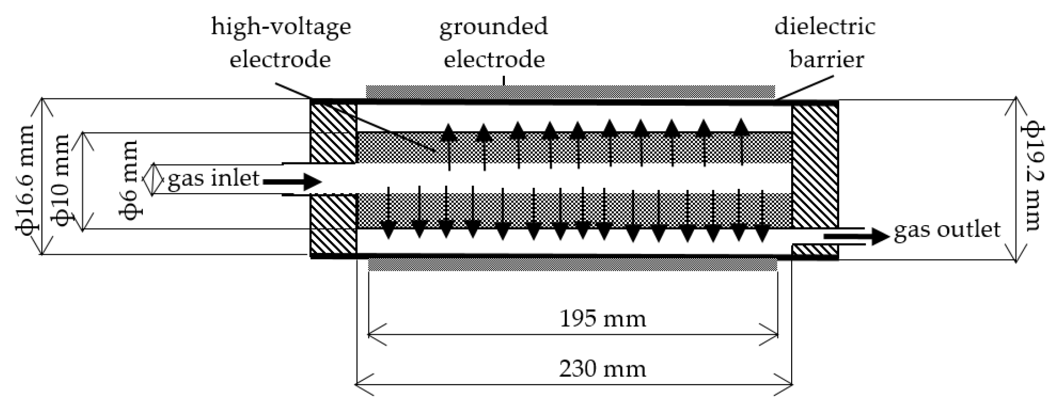
Apparatus and reactor diagrams are shown in Figure 1 and Figure 2. The reactor casing was made of a quartz tube, and the tube was a dielectric barrier. The quartz tube’s outer and inner diameters were 19.2 and 16.6 mm, respectively. The outside of the quartz tube was covered with conductive aluminum paint over a length of 195 mm. This paint was a grounded electrode. A high-voltage electrode was a porous stainless-steel tube. The high-voltage electrode’s outer and inner diameters were 10 and 6 mm, respectively. The open porosity of this electrode was relatively high and amounted to 19%. A feed gas was introduced into the discharge gap (plasma zone) through the pores in the stainless-steel electrode.

2.2. Electrical Measurements

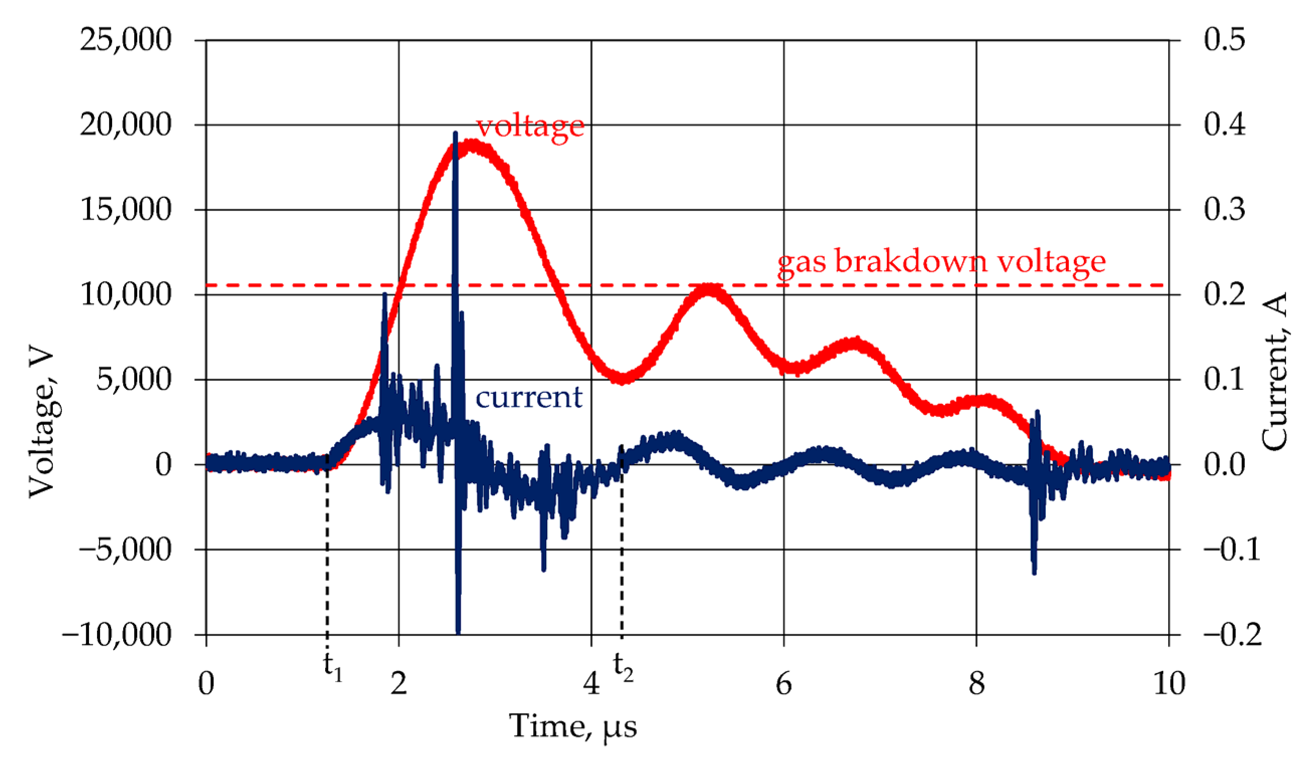
The reactor was powered by a pulsed power supply system that allowed high conversion at low power [4]. The output voltage had positive polarity, and its maximum value was 9 kV. Due to the pulsed power supply, the Lissajous graph measurement technique for a discharge power measurement was unsuitable, and voltage and current measurements were used [4,40]. Electrical characteristics of discharge in time (t, s), e.g., frequency (f, Hz), voltage (u, V), and current (i, A), were recorded using an oscilloscope Tektronix TDS 3032B with a voltage probe Tektronix P6015A (accuracy 3%) and a current probe Tektronix TCP202 (accuracy 3%) (Tektronix Inc., Beaverton, OR, USA). The power of the discharge (P, W) was calculated, in limits shown in Figure 3, according to the formula:
P = f ∫|u(t)∙i(t)|dt,
The average of ten recordings is power, and the standard calculation error is 12%.
Integration was limited to the first voltage peak only. The second voltage peak is close to the gas breakdown voltage in gas, but the time elapsed since the first peak is very short, and charges could not accumulate on the dielectric surface. Therefore, it was assumed that the subsequent voltage and current peaks are related to capacitance discharge in the reactor and power supply. This approach causes that part of the energy dissipated outside the discharge to be omitted. Increasing the integration limit and including subsequent peaks would increase the power by 30%.

2.3. Chemical Analysis

A Hewlett-Packard HP 6890 gas chromatograph (Hewlett-Packard Inc., Palo Alto, CA, USA) with a flame ionization detector was used to measure VOC concentrations. Each experimental point is the average of three measurements. The measurement accuracy was 3%. An Agilent 6890N gas chromatograph (Agilent Technologies Inc., Santa Clara, CA, USA) with a thermal conductivity detector was used to measure carbon oxide concentrations (CO2, CO). The measurement accuracy was 5%. Chlorine (Cl2) and phosgene (COCl2) were analyzed using titrate analyses [41]. The accuracy of these analyses was 0.5%. Other research teams have also used titration analysis [6,7,42,43]. Gas was periodically passed through two bubblers with potassium iodide (KI) water solution. It was essential to measure the gas flow time through bubblers accurately. Ozone, which also reacts with potassium iodide, was decomposed after leaving the reactor at a temperature of 200 °C in the deozonator (Figure 1). Cl2 reacted with KI in these bubblers to form iodine (I2) and potassium chloride (KCl). COCl2 reacted with H2O to form hydrochloric acid (HCl) and CO2. HCl dissociated in water to Cl and H+. The solution obtained in the bubblers was titrated with sodium thiosulfate (0.05 M Na2S2O3) using starch as the indicator and then with sodium hydroxide (0.1 M NaOH) using methyl orange as the indicator to measure the amount of I2 and Cl, respectively [41]. The titrate analysis could not be done separately for COCl2, HCl, and Cl. Chromatographic measurements and titration analysis did not determine what amount of chlorine dioxide (ClO2) was formed. Therefore, its amount was calculated from the mass balance of chlorine.
The initial concentration of organochlorine compound in the air was low (0.4%). Therefore, the change in gas volume resulting from the reaction and absorption of some products was neglected. For the calculations, it was assumed that the flow of gases leaving the reactor was the same as that of gases feeding the reactor. The molar flow of individual chemical compounds was calculated according to the formula:
Wout[i] = F∙ci/22.4,
where Wout[i]—flow rate of compound i, mol/h
ci—volume fraction of compound i
22.4—molar volume of gas in standard conditions, L/mol
The CHCl3 or C2HCl3 conversions (x, %) and selectivity (S, %) of conversion to various products were calculated according to formulas:
x = (Win[VOCs] − Wout[VOCs])/Win[VOCs]∙100%,
SCOCl2 = 2/3∙W[COCl2]/(Win[VOCs] − Wout[VOCs])∙100%,
SCl2 = 2/3∙W[Cl2]/(Win[VOCs] − Wout[VOCs])∙100%,
SCCl4 = 4/3∙W[CCl4]/(Win[VOCs] − Wout[VOCs])∙100%,
SClO2 = 1/3∙W[ClO2]/(Win[VOCs] − Wout[VOCs])∙100%,
where SCOCl2—selectivity of CHCl3 or C2HCl3 conversion to COCl2, %
SCl2—selectivity of CHCl3 or C2HCl3 conversion to Cl2, %
SCCl4—selectivity of CHCl3 or C2HCl3 conversion to CCl4, %
SClO2—selectivity of CHCl3 or C2HCl3 conversion to ClO2, %
Win[VOCs]—CHCl3 or C2HCl3 flow rate at the inlet, mol/h
Wout[VOCs]—CHCl3 or C2HCl3 flow rate at the outlet, mol/h
W[COCl2]—COCl2 flow rate at the outlet, mol/h
W[Cl2]—Cl2 flow rate at the outlet, mol/h
W[CCl4]—CCl4 flow rate at the outlet, mol/h
W[ClO2]—ClO2 flow rate at the outlet, mol/h

3. Results and Discussion

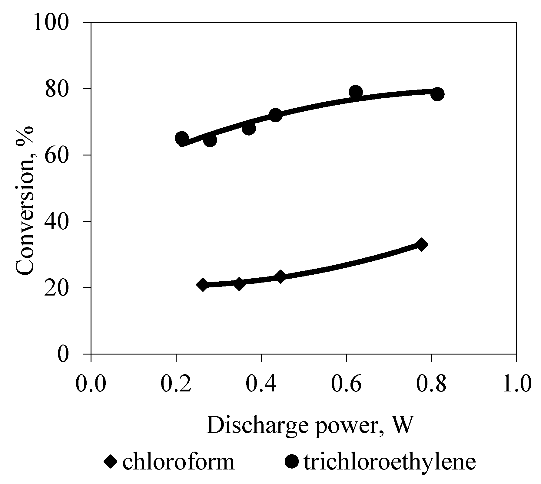
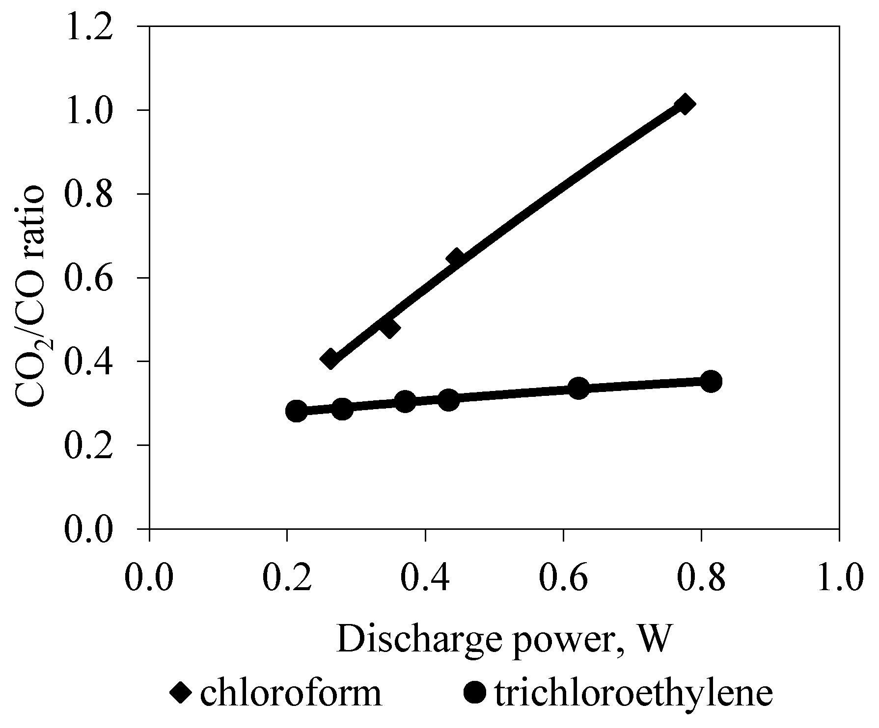
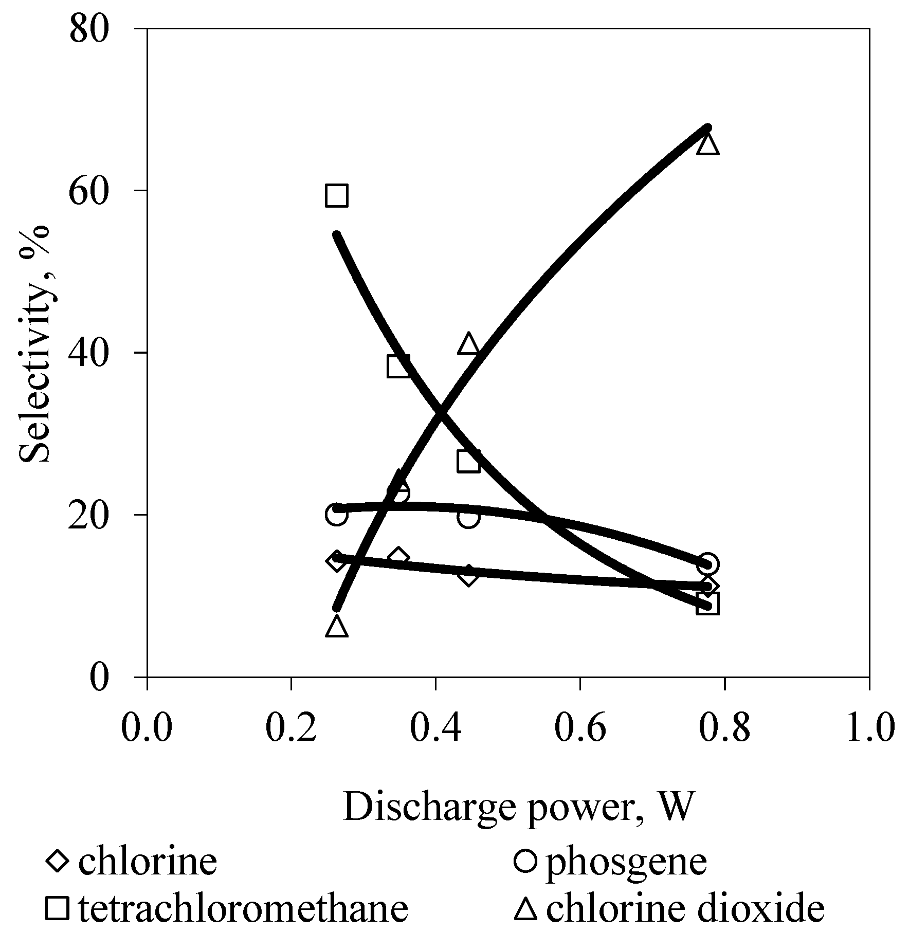
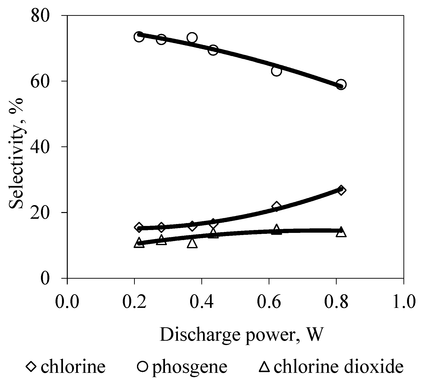
Chloroform and trichloroethylene decomposition results for various discharge powers are shown in Figure 4, Figure 5, Figure 6 and Figure 7. Figure 4 shows that the CHCl3 and C2HCl3 conversion increases with increasing discharge power. It is also apparent (Figure 4) that the C2HCl3 conversion was two to three times higher than the CHCl3 conversion. The CO2/CO ratio increases with the increasing discharge power for both compounds (Figure 5). The CO2/CO ratio increase is slight for trichloroethylene compared to chloroform, but the CO2/CO ratio still increases. Despite the very high oxygen-to-organochlorine compound ratio, the gas has more CO than CO2. This effect is probably due to the short residence time of the reactants in the micro-discharge channels. After leaving the micro-discharge channels, the temperature of the gases decreases quickly [44], and oxidation of CO to CO2 does not occur. Oxidation of CO requires high temperature. CO is a poison that must be removed from the gas or oxidized to CO2.
Products containing chlorine formed during the decomposition process of CHCl3 and C2HCl3 were not the same (Figure 6 and Figure 7). The CHCl3 and C2HCl3 decomposition results indicate that the decomposition mechanisms of these compounds differed. The difference is due to the different structures of CHCl3 and C2HCl3.
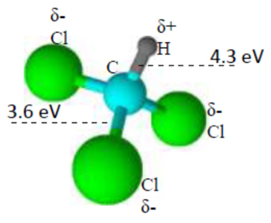
There are polarized covalent bonds in the trichloromethane molecule. Polarization results from differences in the properties of the elements that form chemical bonds. The Pauling electronegativity of carbon, chlorine, and hydrogen is 2.55, 3.16, and 2.2, respectively. The electron pair, forming a bond, shifts towards the more electronegative element in polarized covalent bonds. Consequently, a partial positive charge is accumulated on the hydrogen atom, and a partial negative charge is accumulated on chlorine atoms (Figure 8). The partial positive charge attracts electrons, whereas the partial negative charge repels electrons. The attraction and repulsion of electrons cause the C–H bond dissociation to initiate CHCl3 decomposition. However, the C–H bond is stronger than the C–Cl bond. Moreover, many oxygen atoms (O) are produced during the micro-discharge in collisions with electrons. However, excited species (O2*, N2*) are also formed in much smaller amounts [45,46]. Collusions with high-energy electrons or atomic oxygen are believed to initiate the decomposition of organochlorine compounds in the dielectric barrier discharge. In the presence of O2, numerical calculations indicate that the critical collision is with atomic oxygen [21]. Experimental research conducted by Han and Oda showed that ozone did not affect the decomposition efficiency of trichloroethylene [20]. Ozone, which occurs in the plasma environment generated in a dielectric barrier discharge, is a product of a three-molecular reaction involving atomic oxygen. For this reason, the concentration of atomic oxygen is much greater than that of ozone [45]. Therefore, reactions involving ozone in processes conducted directly in the plasma are less important than reactions involving atomic oxygen and high-energy electrons. However, reactions with it are significant in introducing ozone into a stream containing pollutants [47,48]. In the research system used in this work, ozone was decomposed immediately after leaving the reactor and could not oxidize substrates or products (e.g., CO). Ozone decomposition was necessary for correct measurements of chlorine concentration.
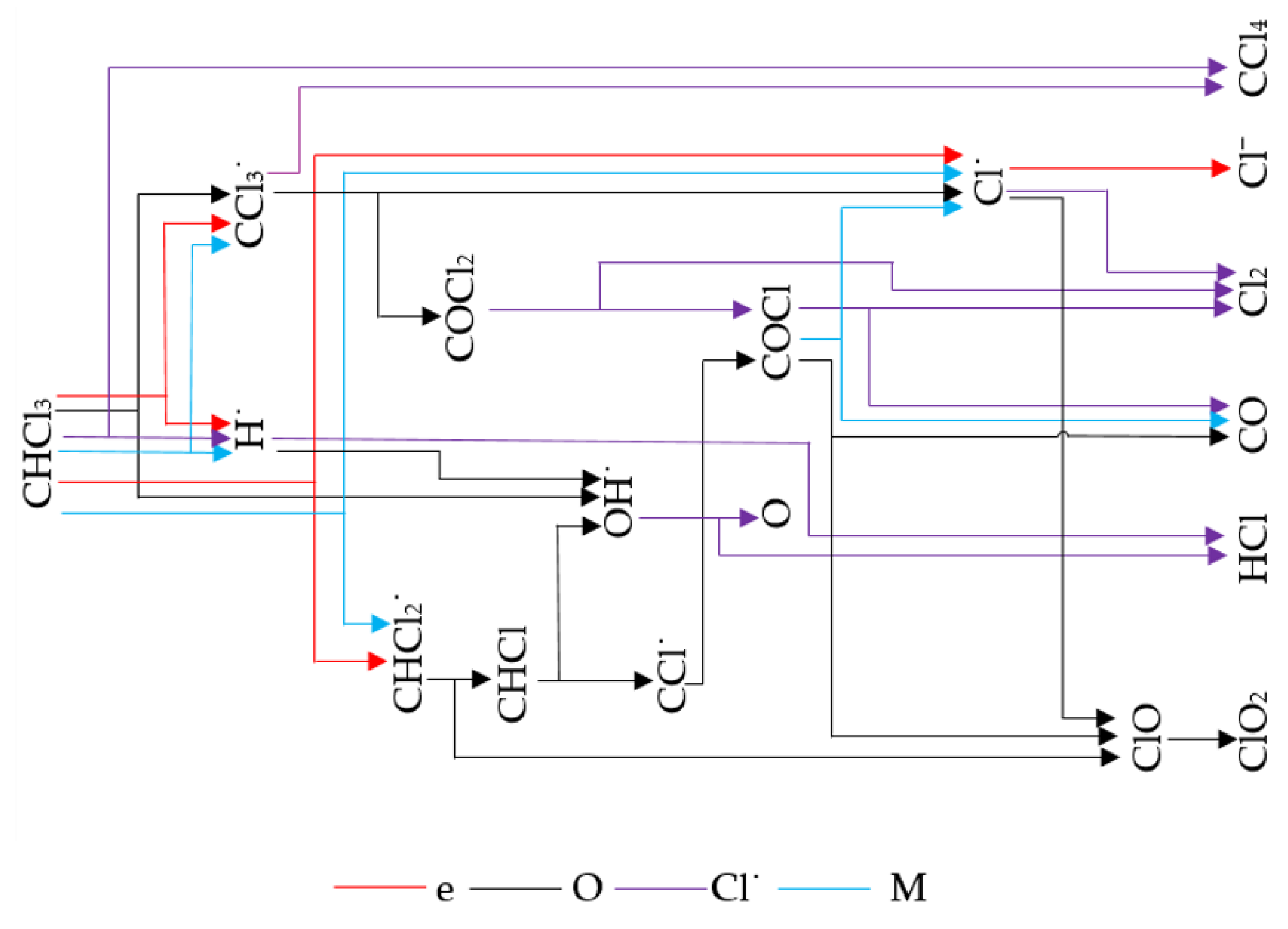
In the reactions between CHCl3 and O, atom H detaches from the molecule CHCl3, and radicals OH and CCl3 are formed [49]. The reactions with other reagents (e.g., O2*, N2*) are not selective. Radicals of H, CCl3, Cl, and CHCl2 may be formed. Then, many reactions lead to the formation of end-products of CHCl3 decomposition. End-products containing chlorine were CCl4, Cl2, or products acidifying the aqueous solution: COCl2, HCl, and Cl. However, the chlorine balance indicates that some chlorine was in unidentified compounds. Results of total Gibbs energy calculations suggest that, most likely, ClO2 was formed [50]. Based on measurements and calculations, a pathway of CHCl3 decomposition in dry air in non-thermal plasma is proposed (Figure 9).
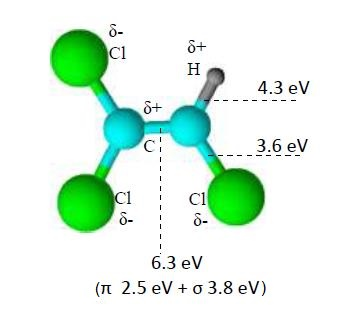
Trichloroethylene structure differs from that of chloroform by two carbon atoms and a double bond between the carbon atoms. A distribution of partial charges in C2HCl3 is similar to one in CHCl3 (Figure 8 and Figure 10). However, the partial positive charge accumulates additionally on one C atom in C2HCl3. Therefore, C2HCl3 is more polar than CHCl3. C2HCl3 and CHCl3 polarizabilities are 10.21 and 8.39 Å3, respectively. The spatial structure of C2HCl3 caused the electron to have easy access to the double bond. Therefore, due to collisions between C2HCl3 and electrons, there may be dissociated C–H and C=C bonds. The binding energy of the double bond is 6.3 eV, but this bond contains π and σ bonds. The π bond is relatively weak, with an energy of 2.5 eV. Therefore, breaking of the π bond is very likely. Next, a radical or anion of chlorine detaches due to an unpaired electron (from the π bond) migration to a chlorine atom. The C=C bond is unstable in the presence of O. The O attaches to C2HCl3, causing the dissociation of the π bond. The O may be attached to one of the two C atoms present in C2HCl3. Energetically favorable is the reaction in which the O attaches to the C atom, which is connected to hydrogen. However, this reaction is not selective because the energy difference is slight (31 kJ/mol), and the O is highly reactive. Therefore, two transient complexes can be formed [51]. Both transient complexes are unstable and decompose to other compounds due to collisions with molecules that can take over part of the energy. Based on information on stable end-products obtained in experiments, total Gibbs energy calculations [50], and published reactions of trichloroethylene [51] and free radicals available in an open database [52], a possible decomposition pathway for trichloroethylene in dry air in a non-thermal plasma is proposed (Figure 11).
How chemical compound structure influences decomposition processes is the subject of many publications presenting the results of model calculations. In recent years, many publications have been concerned with using the density functional theory (DFT) model, which allows calculations of various parameters characterizing chemical reactions, e.g., reaction energy thresholds or attack sites of the molecule [21,53,54,55,56]. Mathematical calculations indicate a higher reactivity of compounds containing a double bond [53]. Experimental results confirm the higher reactivity of compounds containing a double bond [47].

4. Conclusions

The results indicate that the chemical structure of organochlorine compounds strongly influences their decomposition process in the pulsed dielectric barrier discharge. The double bond and greater polarizability of C2HCl3 than CHCl3 caused the C2HCl3 decomposition to be much easier than CHCl3 decomposition. Therefore, the C2HCl3 conversion was much higher than the conversion of CHCl3. The conversion of trichloroethylene reaches 78%, whereas that of chloroform reaches only 33%. The number of Cl atoms is the same in both compounds, but dissociating the weak π bond (2.5 eV) allowed easy decomposition of C2HCl3 by the detachment of the Cl anion or the reactive Cl radical. Consequently, the number of Cl anions and radicals was higher during the decomposition of C2HCl3 than during the decomposition of CHCl3. This results in a higher selectivity of conversion to Cl2. For trichloroethylene, the selectivity of conversion to Cl2 ranges from 16 to 27%. For chloroform, the selectivity of conversion to Cl2 ranges from 11 to 15%.

Funding

This research was funded by the Warsaw University of Technology.

Data Availability Statement

The data is included in the article.

Conflicts of Interest

The author declares no conflicts of interest.

References

  1. Krawczyk, K.; Jodzis, S.; Lamenta, A.; Kostka, K.; Ulejczyk, B.; Schmidt–Szałowski, K. Carbon tetrachloride decomposition by pulsed spark discharges in oxidative and nonoxidative conditions. IEEE Trans. Plasma Sci. 2011, 39, 3203–3210. [Google Scholar] [CrossRef]
  2. Ulejczyk, B.; Krawczyk, K.; Młotek, M.; Schmidt–Szałowski, K.; Nogal, Ł.; Kuca, B. A comparison of carbon tetrachloride decomposition using spark and barrier discharges. Open Chem. 2015, 13, 509–516. [Google Scholar] [CrossRef]
  3. Magureanu, M.; Mandache, N.B.; Parvulescu, V.I. Chlorinated organic compounds decomposition in a dielectric barrier discharge. Plasma Chem. Plasma Process. 2007, 27, 679–690. [Google Scholar] [CrossRef]
  4. Ulejczyk, B.; Krawczyk, K.; Młotek, M.; Schmidt–Szałowski, K.; Nogal, Ł.; Kuca, B. Decomposition of carbon tetrachloride in the reactor of dielectric barrier discharge with different power supplies. Eur. Phys. J. Appl. Phys. 2013, 61, 24324. [Google Scholar] [CrossRef]
  5. Mustafa, M.F.; Fu, X.; Liu, Y.; Abbas, Y.; Wang, H.; Lu, W. Volatile organic compounds (VOCs) removal in non-thermal plasma double dielectric barrier discharge reactor. J. Hazard. Mater. 2018, 347, 317–324. [Google Scholar] [CrossRef]
  6. Gushchin, A.A.; Grinevich, V.I.; Kozlov, A.A.; Izvekova, T.V.; Kvitkova, E.Y.; Rybkin, V.V. Kinetics of 1,4-Dichlorobenzene decomposition in an atmospheric pressure dielectric barrier discharge in oxygen. High Energy Chem. 2020, 54, 64–68. [Google Scholar] [CrossRef]
  7. Gushchin, A.A.; Grinevich, V.I.; Izvekova, T.V.; Kvitkova, E.Y.; Tyukanova, K.A.; Rybkin, V.V. Decomposition of carbon tetrachloride under the action of a dielectric barrier discharge of atmospheric pressure in an oxygen atmosphere. Chemosphere 2021, 270, 129392. [Google Scholar] [CrossRef]
  8. Sivachandiran, L.; Karuppiah, J.; Subrahmanyam, C. DBD plasma reactor for oxidative decomposition of chlorobenzene. Int. J. Chem. React. Eng. 2012, 10, A62. [Google Scholar] [CrossRef]
  9. Rubio, S.J.; Quintero, M.C.; Rodero, A. Application of microwave air plasma in the destruction of trichloroethylene and carbon tetrachloride at atmospheric pressure. J. Hazard. Mater. 2011, 186, 820–826. [Google Scholar] [CrossRef]
  10. Bo, Z.; Yan, J.H.; Li, X.D.; Chi, Y.; Cen, K.F.; Cheron, B.G. Effects of oxygen and water vapor on volatile organic compounds decomposition using gliding arc gas discharge. Plasma Chem. Plasma Process. 2007, 24, 155–167. [Google Scholar] [CrossRef]
  11. Krawczyk, K.; Ulejczyk, B. Influence of water vapor on CCl4 and CHCl3 conversion in gliding discharge. Plasma Chem. Plasma Process. 2004, 24, 155–167. [Google Scholar] [CrossRef]
  12. Vandenbroucke, A.M.; Aerts, R.; Van Gaens, W.; De Geyter, N.; Leys, C.; Morent, R.; Bogaerts, A. Modeling and experimental study of trichloroethylene abatement with a negative direct current corona discharge. Plasma Chem. Plasma Process. 2015, 35, 217–230. [Google Scholar] [CrossRef]
  13. Cucciniello, R.; Intiso, A.; Siciliano, T.; Palomares, A.E.; Martínez-Triguero, J.; Cerrillo, J.L.; Proto, A.; Rossi, F. Oxidative Degradation of Trichloroethylene over Fe2O3-doped Mayenite: Chlorine Poisoning Mitigation and Improved Catalytic Performance. Catalysts 2019, 9, 747. [Google Scholar] [CrossRef]
  14. Zhang, X.; Liu, Y.; Deng, J.; Zhang, K.; Yang, J.; Han, Z.; Dai, H. AuPd/3DOM TiO2 Catalysts: Good Activity and Stability for the Oxidation of Trichloroethylene. Catalysts 2018, 8, 666. [Google Scholar] [CrossRef]
  15. Schmidt, A.; Lerch, M.; Eufinger, J.-P.; Janek, J.; Tranca, I.; Islam, M.M.; Bredow, T.; Dolle, R.; Wiemhofer, H.-D.; Boysen, H.; et al. Chlorine ion mobility in Cl-mayenite (Ca12Al14O32Cl2): An investigation combining high-temperature neutron powder diffraction, impedance spectroscopy and quantum-chemical calculations. Solid State Ion. 2014, 254, 48–58. [Google Scholar] [CrossRef]
  16. Potylitsyna, A.R.; Rudneva, Y.V.; Bauman, Y.I.; Plyusnin, P.E.; Stoyanovskii, V.O.; Gerasimov, E.Y.; Vedyagin, A.A.; Shubin, Y.V.; Mishakov, I.V. Efficient Production of Segmented Carbon Nanofibers via Catalytic Decomposition of Trichloroethylene over Ni-W Catalyst. Materials 2023, 16, 845. [Google Scholar] [CrossRef]
  17. Mishakov, I.V.; Vedyagin, A.A.; Bauman, Y.I.; Potylitsyna, A.R.; Kadtsyna, A.S.; Chesnokov, V.V.; Nalivaiko, A.Y.; Gromov, A.A.; Buyanov, R.A. Two Scenarios of Dechlorination of the Chlorinated Hydrocarbons over Nickel-Alumina Catalyst. Catalysts 2020, 10, 1446. [Google Scholar] [CrossRef]
  18. He, Y.; Shen, J.; Alharbi, N.S.; Chen, C. Volatile organic compounds degradation by nonthermal plasma: A review. Environ. Sci. Pollut. Res. 2023, 30, 32123–32152. [Google Scholar] [CrossRef] [PubMed]
  19. Gomez–Ramirez, A.; Montoto–Damas, A.M.; Rodriguez, M.A.; Gonzalez–Elipe, A.R.; Cotrino, J. Improving the pollutant removal efficiency of packed-bed plasma reactors incorporating ferroelectric components. Chem. Eng. J. 2017, 314, 311–319. [Google Scholar] [CrossRef]
  20. Han, S.B.; Oda, T. Decomposition mechanism of trichloroethylene based on by-product distribution in the hybrid barrier discharge plasma process. Plasma Sources Sci. Technol. 2007, 16, 413–421. [Google Scholar] [CrossRef]
  21. Liu, L.; Shao, G.; Ma, C.; Nikiforov, A.; De Gryter, N.; Morent, R. Plasma-catalysis for VOCs docomposition: A review on micro- and macroscopic modeling. J. Hazard. Mater. 2023, 451, 131100. [Google Scholar] [CrossRef] [PubMed]
  22. Meloni, E.; Cafiero, L.; Renda, S.; Martino, M.; Pierro, M.; Palma, V. Ru- and Rh-Based catalysts for CO2 methanation assisted by non-thermal plasma. Catalysts 2023, 13, 488. [Google Scholar] [CrossRef]
  23. Li, J.; Ma, C.; Zhu, S.; Yu, F.; Dai, B.; Yang, D. A Review of recent advances of dielectric barrier discharge plasma in catalysis. Nanomaterials 2019, 9, 1428. [Google Scholar] [CrossRef]
  24. Michielsen, I.; Uytdenhoiwen, Y.; Pype, J.; Michielsen, B.; Mertens, J.; Reniers, F.; Meynen, V.; Bogaerts, A. CO2 dissociation in a bed DBD reactors: First step towards a better understanding of plasma catalysis. Chem. Eng. J. 2017, 326, 477–488. [Google Scholar] [CrossRef]
  25. Van’t Veer, K.; Engelmann, Y.; Reniers, F.; Bogaerts, A. Plasma-Catalytic ammonia synthesis in a DBD plasma: Role of microdischarges and their afterglows. J. Phys. Chem. C 2020, 124, 22871–22883. [Google Scholar] [CrossRef]
  26. Jodzis, S. Effect of silica packing on ozone synthesis from oxygen-nitrogen mixtures. Ozone Sci. Eng. 2003, 25, 63–72. [Google Scholar] [CrossRef]
  27. Ulejczyk, B.; Nogal, Ł.; Młotek, M.; Falkowski, P.; Krawczyk, K. Hydrogen production from ethanol using a special multi-segment plasma-catalytic reactor. J. Energy Inst. 2021, 95, 179–186. [Google Scholar] [CrossRef]
  28. Abdallah, G.; Giraudon, J.-M.; Bitar, R.; Geyter, N.D.; Morent, R.; Lamonier, J.-F. Post-Plasma Catalysis for Trichloroethylene Abatement with Ce-Doped Birnessite Downstream DC Corona Discharge Reactor. Catalysts 2021, 11, 946. [Google Scholar] [CrossRef]
  29. Shahna, F.G.; Ebrahimi, H.; Jahel, B.; Bahrami, A. Decomposition of gas-phase chloroform using nonoptotocatalyst downstream the novel non-thermal plasma reactor: By products elimination. Int. J. Environ. Sci. Technol. 2015, 12, 3489–3498. [Google Scholar] [CrossRef]
  30. Subrahmanyam, C.; Magureanu, M.; Renken, A.; Kiwi-Minsker, L. Catalytic abatement of volatile organic compounds assisted by non-thermal plasma: Part 1. A novel dielectric barrier discharge reactor containing catalytic electrode. Appl. Catal. B Environ. 2006, 65, 150–156. [Google Scholar] [CrossRef]
  31. Cheng, L.; Ghobeira, R.; Cools, P.; Luthringer, B.; Asadian, M.; De Geyter, N.; Liu, Z.; Yan, K.; Morent, R. Comparing medium pressure dielectric barrier discharge (DBD) plasmas and classic methods of surface cleaning/activation of pure Mg for biomedical applications. Surf. Coat. Technol. 2021, 410, 126934. [Google Scholar] [CrossRef]
  32. Trinh, Q.H.; Hossain, M.M.; Kim, S.H.; Mok, Y.S. Tailoring the wettability of glass using a double-dielectric barrier discharge reactor. Heliyon 2018, 4, e00522. [Google Scholar] [CrossRef] [PubMed]
  33. Siemak, J.; Ulejczyk, B.; Mikołajczak, G.; Pęksiński, J.; Sreńscek-Nazzal, J.; Młotek, M.; Krawczyk, K.; Michalkiewicz, B. Cold Nitrogen Plasma: A Groundbreaking Eco-Friendly Technique for the Surface Modification of Activated Carbon Aimed at Elevating Its Carbon Dioxide Adsorption Capacity. Appl. Sci. 2024, 14, 6438. [Google Scholar] [CrossRef]
  34. Opalińska, T.; Ulejczyk, B.; Schmidt–Szałowski, K. Applications of pulsed discharge to thin-film deposition. IEEE Trans. Plasma Sci. 2009, 37, 934–940. [Google Scholar] [CrossRef]
  35. Wnukowski, M. Methane Pyrolysis with the use of plasma: Review of plasma reactors and process products. Energies 2023, 16, 6441. [Google Scholar] [CrossRef]
  36. Panda, N.R.; Sahu, D. Enhanced hydrogen generation efficiency of methanol using dielectric barrier discharge plasma methodology and conducting sea water as an electrode. Heliyon 2020, 6, e04717. [Google Scholar] [CrossRef]
  37. Ulejczyk, B.; Nogal, Ł.; Młotek, M.; Krawczyk, K. Hydrogen production from ethanol using dielectric barrier discharge. Energy 2019, 174, 261–268. [Google Scholar] [CrossRef]
  38. Kogelschatz, U.; Eliansson, B.; Egli, W. Dielectric-Barrier Discharges. Principle and Applications. J. De Phys. IV Fr. 1997, 7, C4-46–C4-66. [Google Scholar] [CrossRef]
  39. Jodzis, S. Temperature effects under ozone synthesis process conditions. Eur. Phys. J. Appl. Phys. 2013, 61, 24319. [Google Scholar] [CrossRef]
  40. Jodzis, S.; Baran, K. The influence of gas temperature on ozone generation and decomposition in ozone generator. How is ozone decomposed? Vacuum 2022, 195, 110647. [Google Scholar] [CrossRef]
  41. Minczewski, J.; Marczenko, Z. Chemia Analityczna 2 Chemiczne Metody Analizy Ilościowej; Wydawnictwo Naukowe PWN: Warszawa, Poland, 2010; pp. 190’231, 285’297. [Google Scholar]
  42. Gushchin, A.A.; Grinevich, V.I.; Izvekova, T.V.; Kvitova, E.Y.; Tyukanova, K.A.; Rybkin, V.V. The Destruction of Carbon Tetrachloride Dissolved in Water in a Dielectric Barrier Discharge in Oxygen. Plasma Chem. Plasma Process. 2019, 39, 461–473. [Google Scholar] [CrossRef]
  43. Häggström, K.; Gunnarsson, M.; Bremert-Jirholm, K.; Simic, N. Method for analysis of ClO2 and Cl2 air emissions from pulp mill. Nord. Pulp Pap. Res. J. 2019, 34, 19–27. [Google Scholar] [CrossRef]
  44. Jodzis, S.; Petryk, J. Computer modeling of gas temperature in the ozonizer gap. Effects generated by a single microdischarge. IEEE Trans. Plasma Sci. 2011, 39, 2126–2127. [Google Scholar] [CrossRef]
  45. Elliason, B.; Hirth, M.; Kogelschatz, U. Ozone synthesis from oxygen in dielectric barrier discharges. J. Phys. D Appl. Phys. 1987, 20, 1421–1437. [Google Scholar] [CrossRef]
  46. Rajasekaran, P.; Bibinov, N.; Awakowicz, P. Characterization of dielectric barrier discharge in air applying current measurement, numerical silulation and emission spectroscopy. arXiv 2012, arXiv:1202.3879. [Google Scholar]
  47. Razumovskii, S.D.; Zaikov, G.E. Kinetics and mechanism of the reaction of ozone with double bond. Russ. Chem. Rev. 1980, 49, 1163–1180. [Google Scholar] [CrossRef]
  48. Wu, Z.; Cravotto, G.; Ondruschka, B.; Stolle, A.; Li, W. Decomposition of chloroform and succinic acid by ozonation in a suction-cavitation system: Effect of gas flow. Sep. Purif. Technol. 2016, 161, 25–31. [Google Scholar] [CrossRef]
  49. Su, M.C.; Lim, K.P.; Michael, J.V.; Hranisavljevic, J.; Xun, Y.M.; Fontijn, A. Kinetics studies of the O(3P) + CH2Cl2 and CHCl3 reactions over the 468–1355 and 499–1090 K ranges using two techniques. J. Phys. Chem. 1994, 98, 8411–8418. [Google Scholar] [CrossRef]
  50. Ulejczyk, B. Decomposition of halocarbons in the pulsed dielectric barrier discharge. In Proceedings of the 2014 International Conference on Optimization of Electrical and Electronic Equipment (OPTIM), Bran, Romania, 22–24 May 2014; pp. 1053–1059. [Google Scholar] [CrossRef]
  51. Upadhyaya, H.P.; Kumar, A.; Naik, P.D.; Sapre, A.V. Discharge flow reaction kinetic studies of O(3P) with chloroethylenes CH2CCl2, CHClCCl2, CCl2CCl2. Chem. Phys. Lett. 2000, 321, 411–418. [Google Scholar] [CrossRef]
  52. Available online: https://webbook.nist.gov/chemistry/ (accessed on 20 July 2024).
  53. Jiao, J.; Xiao, D.; Zhang, X.; Deng, Y. Analysis of the molecular structure and vertical electron affinity of organic gas impact on electric strength. Plasma Sci. Technol. 2016, 18, 554–559. [Google Scholar] [CrossRef]
  54. Choi, H.; Park, Y.C.; Im, Y.H.; Kwon, D.C.; Chung, S.Y. A DFT study on direct CF2 fragmentation mechanisms of 1,3-C4F6 and 1,3- C4F6+ in plasma. Plasma Chem. Plasma Process. 2023, 43, 47–66. [Google Scholar] [CrossRef]
  55. Zhao, J.; Zhang, A.; Zhang, Y.; Heroux, P.; Zhu, L.; Li, X.; Li, P.; Liu, Y. Remediation of polychlorinated biphenyls (PCBs) polluted soil using dielectric barrier discharge (DBD) plasma: Reactive nitrogen species (RNS) and produced dioxins. Chem. Eng. J. 2023, 459, 141632. [Google Scholar] [CrossRef]
  56. Boutadghart, T.; Ghailane, R. DFT mechanistic study of [4+2] cycloaddition reactions of 1-mathyl-1-H-pyrrole-2,5-dione with furoic acid, anticancer activity, molecular modeling and ADMET properties of new products from the norcantharimide family substituted by a carboxylic acid. Comput. Theor. Chem. 2023, 1230, 114384. [Google Scholar] [CrossRef]
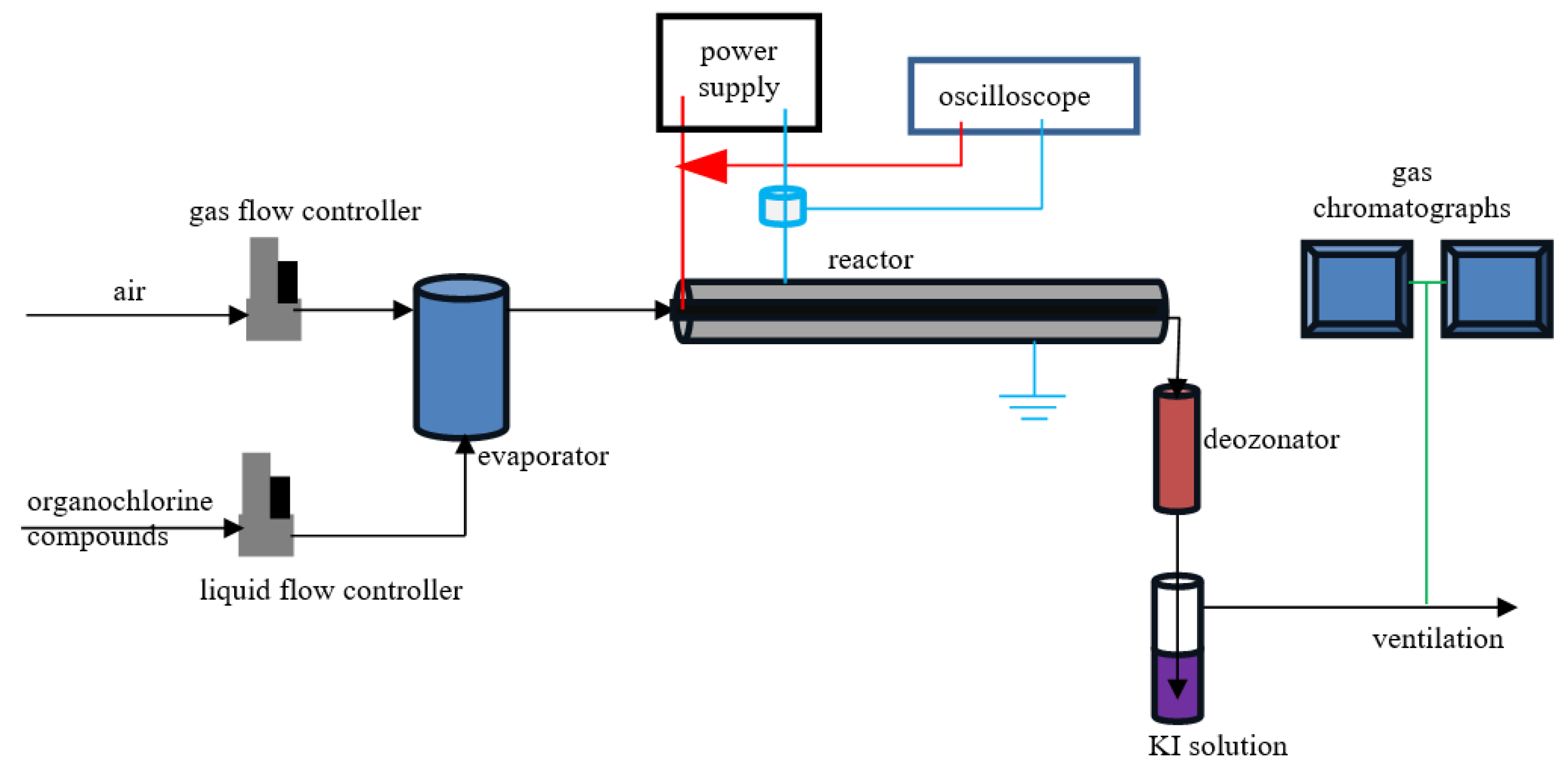
Figure 1. Schema of apparatus. Lines: black—gas flow, red—high voltage, blue—neutral/ground, green—analytical sample.
Reactions 05 00031 g001
Figure 2. Reactor.
Figure 2. Reactor.
Reactions 05 00031 g002
Figure 3. Voltage (red) and current (blue) waveforms. t1, t2—integration limits.
Reactions 05 00031 g003
Figure 4. Conversion of chloroform and trichloroethylene.
Reactions 05 00031 g004
Figure 5. CO2/CO ratio for conversion of chloroform and trichloroethylene.
Reactions 05 00031 g005
Figure 6. Selectivity of chloroform decomposition to various products.
Reactions 05 00031 g006
Figure 7. Selectivity of trichloroethylene decomposition to various products.
Reactions 05 00031 g007
Figure 8. Chloroform structure. C–Cl bonds lengths are 1.796 Å, C–H bond length is 1.127 Å. Angles between the bonds are 109.5°.
Reactions 05 00031 g008
Figure 9. Pathway of chloroform decomposition. M is the collision partner, e.g., O2*, N2*. *—excited species, ·—radical.
Reactions 05 00031 g009
Figure 10. Trichloroethylene structure. C–Cl bonds lengths are 1.72 Å, C–H bond length is 1.111 Å, and C=C bond length is 1.34 Å. Angles between the bonds are 120°.
Reactions 05 00031 g010
Figure 11. Pathway of trichloroethylene decomposition. M is the collision partner, e.g., O2*, N2*. *—excited species, —radical.
Reactions 05 00031 g011
Disclaimer/Publisher’s Note: The statements, opinions and data contained in all publications are solely those of the individual author(s) and contributor(s) and not of MDPI and/or the editor(s). MDPI and/or the editor(s) disclaim responsibility for any injury to people or property resulting from any ideas, methods, instructions or products referred to in the content.