1. Introduction
Rotating machine units used in industrial and agricultural equipment increasingly operate under variable technological loads, frequent start-up cycles, and tighter requirements for productivity and energy efficiency. Under these conditions, the motor, transmission, supporting structure, and working members cannot always be treated as dynamically independent components. Elastic deformation, damping, backlash, inertia distribution, and electromagnetic torque variation cause energy exchange between subsystems and may produce transient overloads, torsional oscillations, and non-uniform rotation. These effects are especially important in machines in which the quality and continuity of a technological process depend directly on the rotational stability of several coupled working members.
Recent studies of geared mechanisms have shown that time-varying mesh stiffness, tribological effects, structural flexibility, and load redistribution strongly influence dynamic response [
1,
2]. Research on controlled transmissions and synchronizing mechanisms has likewise demonstrated that transient motion is governed by the interaction of actuator characteristics, inertia, stiffness, and control laws [
3,
4,
5,
6,
7]. These findings support the use of system-level models rather than isolated component models when the objective is to predict start-up behaviour, vibration, and power demand.
Integrated modeling of electric motors and mechanical transmissions has become a major direction in rotating machinery research. Electromechanical models of motor–gearbox systems demonstrate that local gear defects, electromagnetic torque pulsations, and mechanical compliance can interact and modify the measured vibration response [
8,
9,
10]. The dynamic response of an induction-motor drive is therefore not fully described by a constant driving torque, particularly during starting and acceleration. Magnetic excitation, voltage distortion, rotor eccentricity, and coupling between lateral and torsional motion may substantially alter the transient load applied to the transmission.
Belt transmissions introduce an additional compliant and dissipative subsystem. Their response depends on belt pretension, nonlinear axial stiffness, transverse vibration, hysteresis, pulley geometry, and operating temperature. Modern analytical, numerical, and experimental studies describe belt drives using distributed-parameter formulations, absolute nodal coordinate methods, viscoelastic models, and data-driven identification [
11,
12,
13,
14,
15,
16,
17,
18,
19,
20]. Nevertheless, in many machine-unit models the belt is still reduced to an ideal kinematic ratio or a single linear spring without experimentally supported damping. Such simplification may be acceptable in steady-state kinematic calculations but is insufficient for evaluating start-up oscillations and rotational irregularity.
Planetary transmissions are attractive for compact machines because they provide large speed ratios, coaxial arrangement, and multiple load paths. At the same time, their dynamics are affected by mesh phasing, manufacturing errors, support flexibility, journal-bearing behaviour, and non-uniform load sharing [
21,
22,
23,
24,
25,
26,
27,
28,
29,
30,
31,
32]. Recent models increasingly include flexible components, multi-tooth contact, local faults, and dynamic mesh forces. These works explain the internal behaviour of planetary stages in detail, but most of them do not combine the planetary stage with the induction-motor transient, belt compliance, and a variable technological resistance acting on agricultural working members.
Dynamic models of asynchronous-motor-driven machinery also show that the mechanical response depends on the representation of the motor characteristic. A constant-torque approximation eliminates the most critical part of the transient process: the rapid variation of electromagnetic torque and angular acceleration during starting. Studies of motor vibration, torsional oscillations, tacholess speed estimation, and electromechanical coupling demonstrate the need to include the motor as an active dynamic subsystem rather than as an external constant load [
33,
34,
35,
36,
37,
38,
39,
40,
41,
42,
43,
44,
45,
46,
47].
The technological object considered in this study is the seed-removing device of a saw-type cotton gin. The device continuously removes seeds from the working chamber and therefore affects process stability, energy demand, and the loading of the main machine. Previous studies of cotton-processing machinery have examined the motion of saw cylinders, distributed-parameter working members, vibration diagnostics, machine-vision inspection, and power consumption [
48,
49,
50,
51,
52,
53,
54]. Fundamental design and mechanical principles of cotton-processing machines are summarized in classical monographs and dissertations [
55,
56,
57]. These studies establish the technological importance of stable rotation, but the drive is often simplified and does not simultaneously include the induction motor, elastic belt, planetary gear, seed-removing tube, auger, and technological resistance.
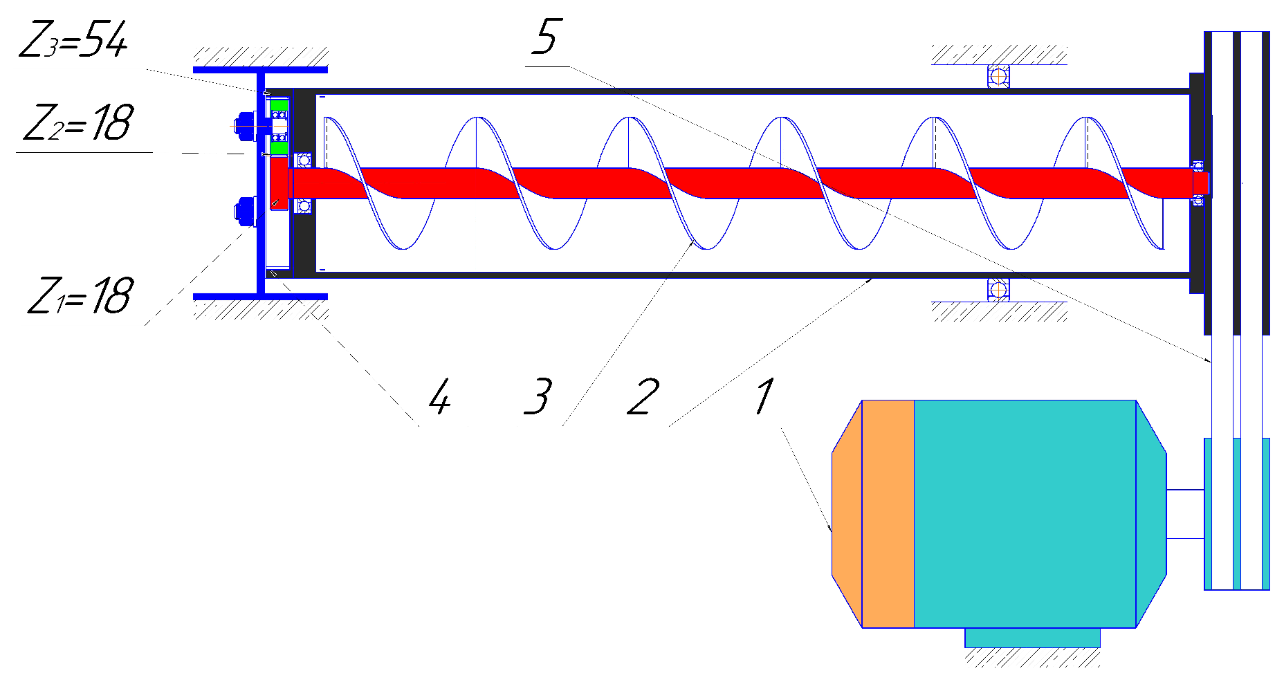
The considered machine unit has a specific coupled architecture. The motor drives the seed-removing tube through a belt transmission. The tube carries the ring gear of a planetary stage. Planet gears rotate on a fixed carrier and drive the sun gear, which is rigidly connected to the auger. Consequently, the tube and auger rotate at different speeds, and their motion is linked by both kinematic constraints and elastic-dissipative interactions. The technological resistance acting on the tube is non-uniform, while the auger is subjected to the torque required to transport seeds. The resulting system contains several inertia, stiffness, damping, and load parameters that influence start-up and steady operation.
The literature review reveals three related gaps. First, existing integrated drivetrain models primarily address motor–gearbox coupling, belt-drive dynamics, or the internal dynamics of planetary transmissions, whereas the combined interaction of an induction motor, compliant belt transmission, planetary stage, and process-loaded working members has received limited attention. Second, cotton-gin studies generally focus on individual working members or employ simplified representations of the motor and transmission, which limits their ability to predict start-up electromechanical transients. Third, the combined effects of inertia, transmission compliance, damping, and technological resistance on the rotational irregularity and power demand of a planetary-driven seed-removing device have not been systematically evaluated.
As summarized in
Table 1, the novelty of the present study does not lie in the individual motor, belt, or planetary-gear models, which are based on established formulations. The contribution is their system-level integration with the process-loaded working members of the seed-removing device. In particular, the model simultaneously represents the induction-motor transient, compliant belt coupling, planetary kinematics, perforated-tube and auger dynamics, and technological resistance. This enables the propagation of transient electromechanical disturbances from the motor to the working members and their effects on rotational irregularity and power demand to be evaluated within a single model.
Accordingly, the objective of this study is to develop and analyze an integrated nonlinear electromechanical model of the machine unit “induction motor–belt transmission–planetary gear–seed-removing tube–auger” and to determine parameter combinations that reduce transient loading, power consumption, and rotational irregularity.
The main contributions of this study are as follows: (1) a unified reduced-order electromechanical model coupling the induction motor, compliant belt drive, planetary transmission, and process-loaded working members; (2) analysis of the propagation of start-up torque and speed transients through the complete machine unit; (3) a quantitative assessment of the influence of inertia, transmission, and resistance parameters on rotational irregularity and power demand; and (4) the identification of rational belt-drive parameters that provide a compromise between dynamic performance and energy consumption.
2. System Description
The investigated machine unit (
Figure 1) is installed in the seed-removing section of a saw-type cotton gin. It consists of an induction motor, a belt transmission, a perforated cylindrical tube, a planetary gear stage, and a screw auger. The motor pulley transmits rotation to the pulley rigidly connected to the seed-removing tube. The tube is rigidly connected to the ring gear (epicycle) of the planetary transmission. Planet gears are mounted on a stationary carrier, and the sun gear is rigidly connected to the auger shaft. This arrangement produces coordinated rotation of the tube and auger while maintaining different angular velocities.
The seed-removing tube performs two functions: it rotates as a working member interacting with the seed mass and simultaneously acts as the input member of the planetary stage. The auger transports the separated seeds toward the discharge zone. The technological resistance of the tube varies periodically because of non-uniform seed distribution and the repeated interaction of the perforated surface with the material. The auger resistance is determined by seed transport and internal friction.
The use of Lagrange’s equations of the second kind provides a systematic formulation of the force and torque interactions in the system, including the elastic-dissipative properties of the drive components, the moments of inertia of the rotor, tube, and auger, and the resistance torques arising during seed transport. This approach enables the derivation of the equations of motion for subsequent analysis of rotational irregularity, rational selection of drive parameters, and reduction of energy consumption.
where
is the
ith generalized angular coordinate and
is the corresponding angular velocity;
T and
V are the total kinetic and potential energies of the system, respectively;
R is the Rayleigh dissipation function; and
is the generalized non-conservative torque associated with
. The index
i identifies the corresponding rotational degree of freedom of the motor, seed-removing tube, planet gears, or auger.
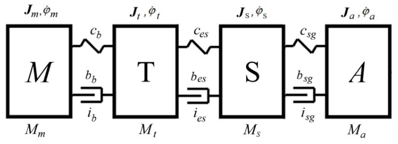
The dynamic model of the machine unit and the kinematic diagram of the seed-removing device are shown in
Figure 2. The following notation is used in the model:
, and are the moments of inertia of the electric motor, seed-removing tube with epicycle, planet gear, and seed-removing auger with sun gear, respectively, ;
, and are the moments of the loads acting on the rotating shaft of the electric motor, seed-removing tube with epicycle, planet gear, and seed-removing auger with sun gear, ;
, and are the torsional stiffness coefficients of the belt drive and gear meshes (epicycle–planet gear and planet gear–sun gear), ;
, and are the damping coefficients of the belt drive and gear meshes (epicycle–planet gear and planet gear–sun gear), ;
, and are the angular velocities of the electric motor rotor, seed-removing tube with the epicycle, planet gear, and auger with the sun gear, rad/s;
, and are the transmission ratios of the belt and gear drives (epicycle–planet gear and planet gear–sun gear).
The belt-drive pulley diameters are
mm on the motor shaft and
mm on the tube shaft. Assuming negligible belt slip, the angular velocities of the motor and the seed-removing tube are related by
Thus, the pulley ratio is
The planetary transmission consists of a sun gear with
teeth, planet gears with
teeth, and a ring gear with
teeth. The gears have a module of
mm and a standard pressure angle of
. The corresponding pitch diameters, calculated as
, are
mm for the sun gear,
mm for each planet gear, and
mm for the internal ring gear. The resulting center distance is
mm for both the external sun–planet and internal planet–ring meshes. The geometrical compatibility condition for the planetary stage,
, is satisfied exactly. The carrier is fixed; therefore, the planet gears rotate about fixed axes. Since the ring gear and the planet gears form an internal gear mesh, their angular velocities have the same sign and satisfy
The planet–sun contact is an external gear mesh; consequently, the planet gear and the sun gear rotate in opposite directions. Since the auger is rigidly connected to the sun gear,
Combining the two planetary-gear relations gives
Accordingly, taking the belt transmission into account,
The signs in the gear ratios indicate the relative directions of rotation. In the reduced dynamic model (
Figure 2), the actual kinematic relationships are retained through the transmission ratios appearing in the elastic and dissipative deformation terms. The four generalized coordinates are the angular displacements of the motor rotor, tube with ring gear, representative planet gear, and auger with sun gear.
Positive angular coordinates and angular velocities are defined in the direction of rotation of the corresponding shaft. Throughout the model, the transmission ratio between two rotating members
i and
j is defined as
A positive transmission ratio () denotes rotation in the same direction, whereas a negative ratio () denotes opposite directions of rotation. This sign convention is retained throughout the kinematic and dynamic equations of the belt and planetary transmissions.
The supports are assumed sufficiently stiff relative to the torsional compliance of the belt and gear contacts. Therefore, support elasticity and housing vibration are not included in the present torsional model. The principal sources of compliance are represented by the belt stiffness , ring–planet mesh stiffness , and planet–sun mesh stiffness . Energy dissipation is represented by the corresponding coefficients , , and .
The compliance terms introduced in the lumped-parameter model represent equivalent torsional mesh stiffnesses referred to the pitch circles of the corresponding gears rather than localized linear tooth-contact stiffnesses. Thus, the tooth-contact deformation is not modeled as an independent translational degree of freedom. Instead, the elastic deformation of each gear mesh is represented by the relative angular displacement of the mating gears, taking the corresponding transmission ratio and direction of rotation into account. If the gear-mesh stiffness is initially expressed as an equivalent linear contact stiffness
(
), its corresponding torsional stiffness referred to a gear pitch circle is
where
is the pitch radius. Accordingly, all gear-mesh stiffness coefficients used in the equations of motion are expressed in
. The same interpretation is used for the elastic elements shown in
Figure 2.
The present lumped-parameter model represents mechanical dissipation through equivalent viscous damping and experimentally determined resistance torques. This formulation is appropriate for describing the overall transient and steady-state dynamics considered in this study, but it does not explicitly reproduce static breakaway friction or the velocity-dependent friction behavior at very low rotational speeds. More detailed friction formulations, including Coulomb and Stribeck models, can improve the representation of mechanical systems during start-up, velocity reversal, and low-speed motion [
58].
Incorporating this nonlinear friction model into the present system would require separate experimental identification of the friction parameters for the bearings and gear contacts. Since these parameters were not independently measured in the present study, introducing them would add unverified parameters to the model. Therefore, the present analysis retains the experimentally based equivalent resistance and damping representation, while nonlinear Coulomb–Stribeck friction is identified as an extension for improving the prediction of breakaway torque and the very early start-up response.
6. Discussion
6.1. Physical Interpretation of the Integrated Response
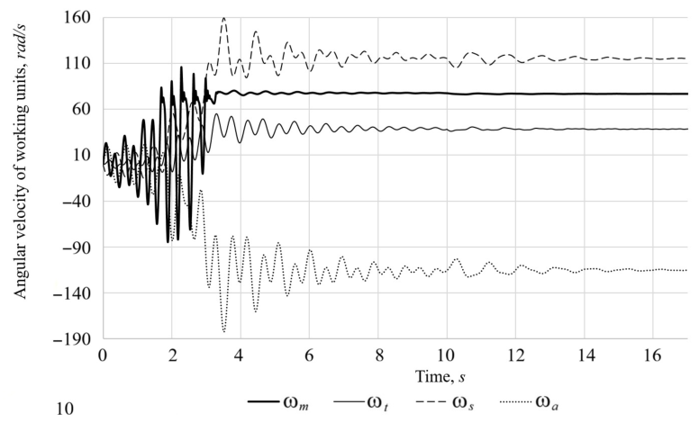
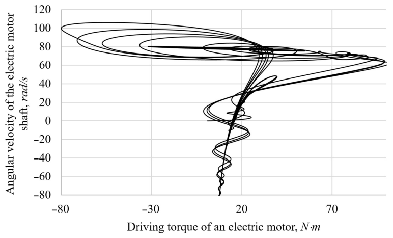
The principal advantage of the proposed formulation is that it preserves the causal path from electromagnetic torque generation to the motion of the technological working members. The motor torque peak first excites relative deformation of the belt. The resulting tube acceleration excites the ring–planet mesh, after which the planet–sun mesh transmits the disturbance to the auger. Therefore, the largest transient torque does not occur simultaneously in all components, and a purely kinematic calculation cannot reproduce the phase relationships or decay rates.
The results agree qualitatively with modern studies of integrated motor–gearbox systems [
8,
9,
10], which show that motor dynamics and mechanical compliance must be solved together. They also support the conclusions of belt-drive research [
11,
12,
13,
14,
15,
16,
17,
18,
19,
20], where stiffness, pretension, and damping control the magnitude and persistence of transient oscillations. In the planetary stage, the present reduced model does not describe local mesh-force distribution with the detail of flexible multi-mesh models [
21,
22,
23,
24,
25,
26,
27,
28,
29,
30,
31], but it captures the system-level energy transmission required for machine-unit design.
6.2. Significance of the Parameter Ranking
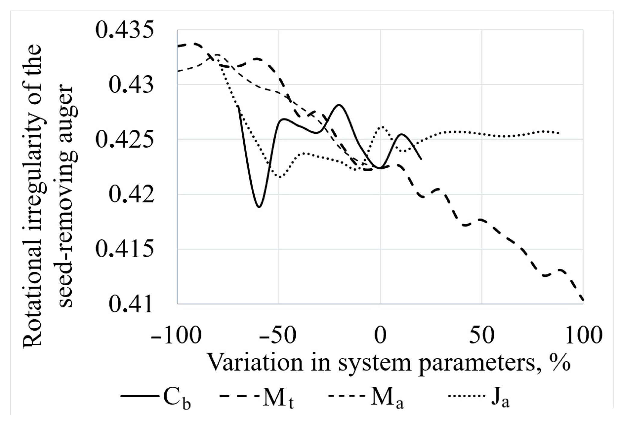
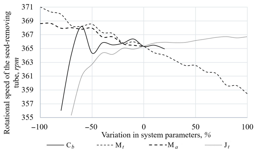
Within the investigated parameter ranges, the sensitivity ranking identifies two principal engineering targets. The tube resistance is a technological parameter governed by seed density, tube perforation, friction, and seed distribution. Reducing its fluctuations requires process and geometry improvements. The auger inertia is a design parameter governed by shaft dimensions, flight geometry, and attached gear mass. Within the considered range, increasing the auger inertia increases the stored oscillatory energy and can amplify the speed variation after a disturbance. In contrast, moderate changes in planet-gear inertia within the investigated range have comparatively little effect on the overall response because the planet gears are relatively small and the load is divided among several identical members.
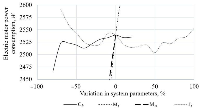
The belt coupling is the most readily adjustable parameter during commissioning and retrofit. However, the result does not imply that the minimum possible stiffness is always desirable. Insufficient stiffness can increase static angular lag, belt slip, and heat generation. The rational design task is therefore to select a belt and pretension that provide adequate mean torque transmission while avoiding excessive excitation of the downstream torsional modes.
6.3. Engineering Implications
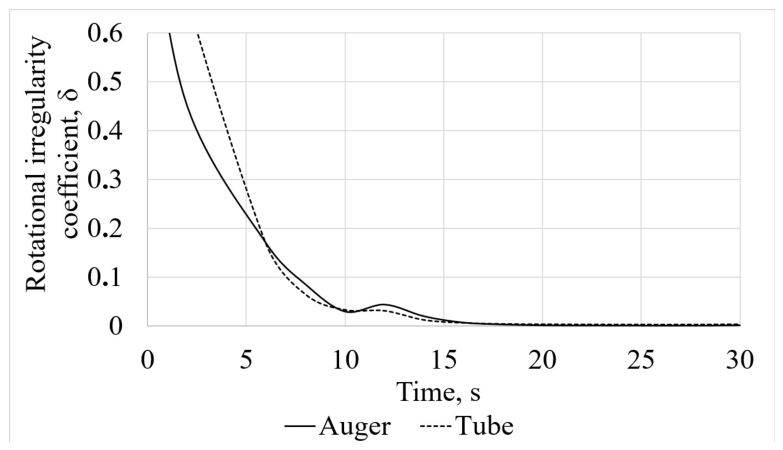
For practical design, the start-up torque ratio of 2.61 should be used when checking belt traction, shaft torque, key and spline strength, and gear-tooth loading. Calculations based only on the rated motor torque may underestimate the short-duration load by more than a factor of two. The approximately 3.5 s motor transient and 7 s tube transient also indicate that repeated start–stop operation should be limited or controlled by a soft starter or variable-frequency drive when process conditions permit.
In production machines, the effective compliance of the belt transmission can be tuned by adjusting belt pretension and tensioner position, selecting the belt profile and material, changing belt width or the number of parallel belts, and modifying pulley diameter and wrap angle. Lower pretension or a more compliant belt can improve torsional vibration isolation, whereas excessive compliance may increase belt deformation and the risk of slip. Conversely, higher pretension or a stiffer belt profile improves traction but increases the transmission of transient torsional loads. Therefore, belt selection and tensioner adjustment should provide a compromise between torsional compliance, traction capacity, and belt service life.
The model can be used to evaluate alternative pulley diameters, gear ratios, auger geometry, and tube perforation parameters. It is also suitable as a basis for rational parameter selection and engineering design guidance, provided that experimentally measured stiffness, damping, and technological torque histories are supplied.
The integration of such data would enable prediction not only of rotational irregularity but also of fatigue-relevant torque cycles.
6.4. Limitations
The present formulation is a reduced torsional model intended primarily for predicting the low-frequency torsional response of the coupled drive, including start-up transients, rotational irregularity, and the overall speed and torque response of the working members. It neglects lateral and axial vibration, bearing and housing flexibility, belt transverse modes, gear backlash, time-varying mesh stiffness, manufacturing errors, and unequal load sharing among the planet gears. In particular, the assumption of constant gear-mesh stiffness suppresses the periodic stiffness modulation associated with tooth engagement and therefore does not reproduce the spectral components at the gear-mesh frequency and its sidebands with sufficient fidelity. Neglecting backlash also excludes intermittent tooth contact, impact excitation, and additional high-frequency torsional components that may occur during torque reversals or transient operation. Consequently, the present model should not be used for direct prediction of high-frequency vibration amplitudes or detailed vibration spectra near the gear-mesh frequency. Such analysis would require a higher-fidelity gear-dynamic model incorporating time-varying mesh stiffness, backlash, tooth-contact excitation, and the relevant structural degrees of freedom.
A limitation of the OFAT approach is that it does not quantify interaction effects between simultaneously varying stiffness, damping, inertia, and technological-load parameters; therefore, the reported sensitivity ranking should be interpreted as a local single-parameter assessment.
6.5. Experimental Validation of the Predicted Operating Parameters
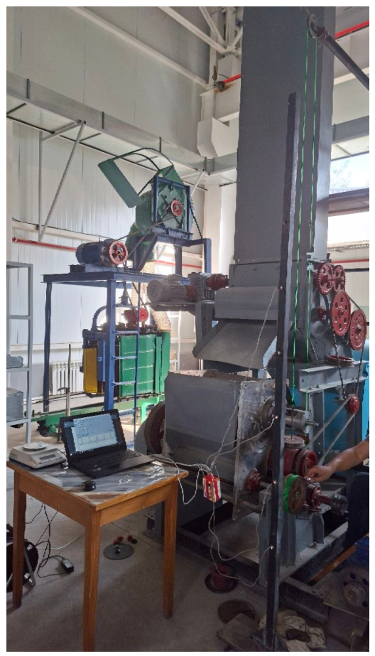
To provide direct experimental validation of the predicted steady-state operating parameters, measurements were performed at eight motor-speed levels ranging from 0 to 735 rpm, including the zero-speed condition. The rotational speed of the induction motor was varied using a variable-frequency drive. At each operating point, after the rotational speeds had stabilized, the motor speed (
), rotational speed of the seed-removing tube (
), and rotational speed of the auger (
) were measured using a tachometer with a specified measurement accuracy of
. Simultaneously, the motor supply voltage and current were recorded to determine the electrical power consumption
P. Each steady-state operating condition was measured once; therefore, standard deviations based on repeated measurements were not determined. The experimental speed values reported in
Table 9 should therefore be interpreted considering the instrumental measurement accuracy of
.
The relative error between the calculated and experimental values was determined as
where
X denotes the tube speed
, auger speed
, or motor power
P. For the zero-speed condition, the relative error is not defined and is therefore indicated by “–” in
Table 9.
The experimental and numerical results show good agreement over the investigated operating range. For the seed-removing tube speed, the relative error ranges from 0.95% to 3.16%, with a maximum value of 3.16%. For the auger speed, the relative error ranges from 1.32% to 4.10%, with a maximum value of 4.10%. The relative error in motor power ranges from 3.07% to 5.02%, with a maximum value of 5.02%. At the nominal motor speed of 735 rpm, the experimental and calculated tube speeds were 367.5 and 363.1 rpm, respectively, corresponding to a relative error of 1.20%. The corresponding experimental and calculated auger speeds were 1102.5 and 1075.5 rpm, with a relative error of 2.45%, while the experimental and calculated motor powers were 2.602 and 2.699 kW, respectively, corresponding to a relative error of 3.72%. Thus, over the investigated non-zero operating points, the maximum deviations did not exceed 3.16% for the tube speed, 4.10% for the auger speed, and 5.02% for motor power. These results provide quantitative experimental support for the ability of the model to reproduce the principal steady-state operating characteristics of the coupled drive.
6.6. Directions for Further Work
Further research aimed at extending the model toward high-frequency vibration prediction should incorporate time-varying gear-mesh stiffness, backlash, tooth-contact excitation, bearing and housing flexibility, and distributed belt dynamics. A multi-objective optimization framework could then be applied to minimize motor power, peak torque, and rotational irregularity while satisfying productivity constraints. Experimental work should quantify the technological torque as a function of seed density and throughput and should identify equivalent belt and mesh damping from measured free-decay or operational-response data.
7. Conclusions
1. A unified reduced-order electromechanical model was developed for the planetary-driven seed-removing machine unit by coupling the induction motor, compliant belt transmission, planetary gear, seed-removing tube, auger, and technological resistance within a single dynamic formulation. The principal contribution is the system-level representation of the interactions between the electrical drive, transmission, and process-loaded working members, rather than the isolated modelling of individual drivetrain components.
2. The analysis demonstrated that the dynamic electromagnetic characteristic of the induction motor must be included when modelling start-up. Its interaction with the compliant belt and planetary transmission governs the propagation of transient torque and speed disturbances through the machine unit and explains the different transient responses of the motor, tube, and auger.
3. Within the investigated parameter ranges, the OFAT sensitivity analysis identified the technological resistance of the seed-removing tube and the inertia of the auger as having the greatest influence on rotational irregularity. In contrast, the inertia and resistance of the planet gears showed a comparatively small system-level influence within the considered ranges. These results provide a physically based local ranking of the investigated parameters for rational parameter selection and engineering design guidance.
4. The study showed that effective belt compliance is an important design parameter linking energy consumption and rotational stability. Appropriate adjustment of belt stiffness and damping can attenuate torsional disturbances and reduce rotational irregularity, although excessive compliance must be avoided because of the associated risk of belt slip and loss of transmission stability.
5. Experimental determination of the rotating-component inertias reduced uncertainty in the model inputs, while measurements of the tube and auger rotational speeds and motor power provided quantitative validation of the predicted steady-state operating characteristics. Over the investigated non-zero operating points, the maximum relative deviations between the numerical predictions and experimental measurements were 3.16% for the tube speed, 4.10% for the auger speed, and 5.02% for motor power. This agreement supports the capability of the model to reproduce the principal steady-state response of the coupled drive within the investigated operating range.
6. The proposed model provides a physically based framework for evaluating transient loads, rotational irregularity, power demand, and parameter sensitivity in planetary-driven cotton-processing machinery. Its predictive scope can be further extended through synchronized transient measurements of torque, speed, current, and vibration and by incorporating time-varying gear-mesh stiffness, backlash, belt transverse dynamics, and support flexibility.





 ,
,