2.3.2. Design of the Compression Mechanism
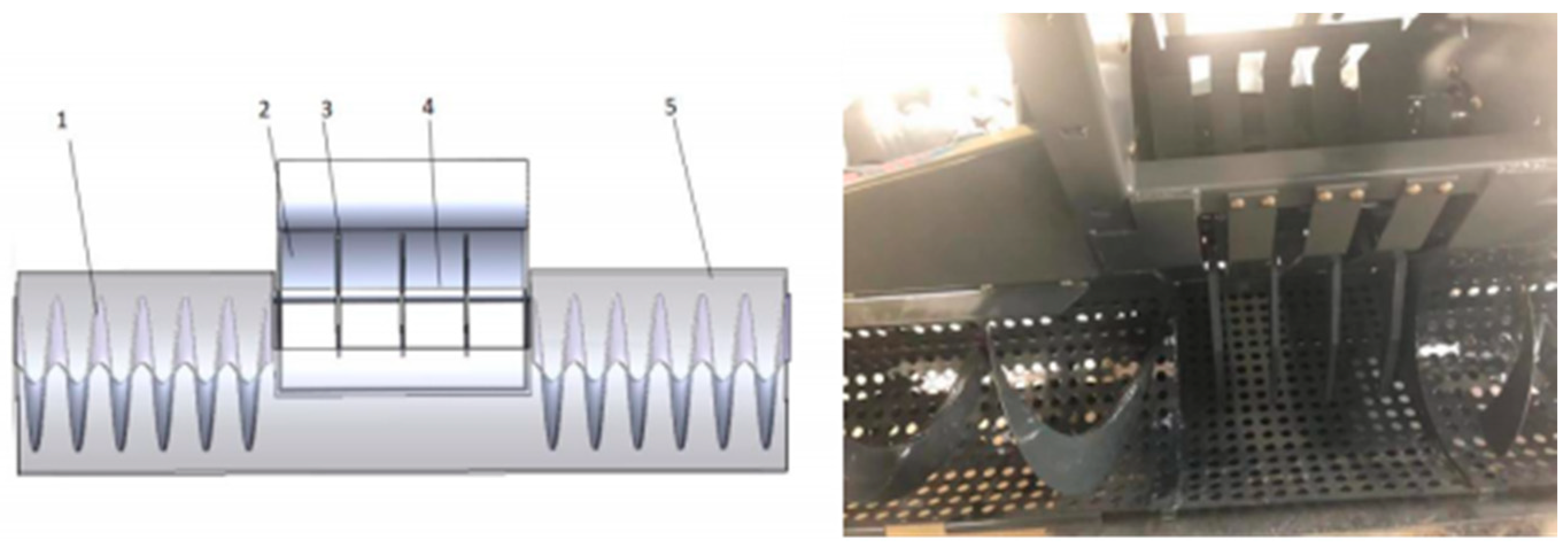
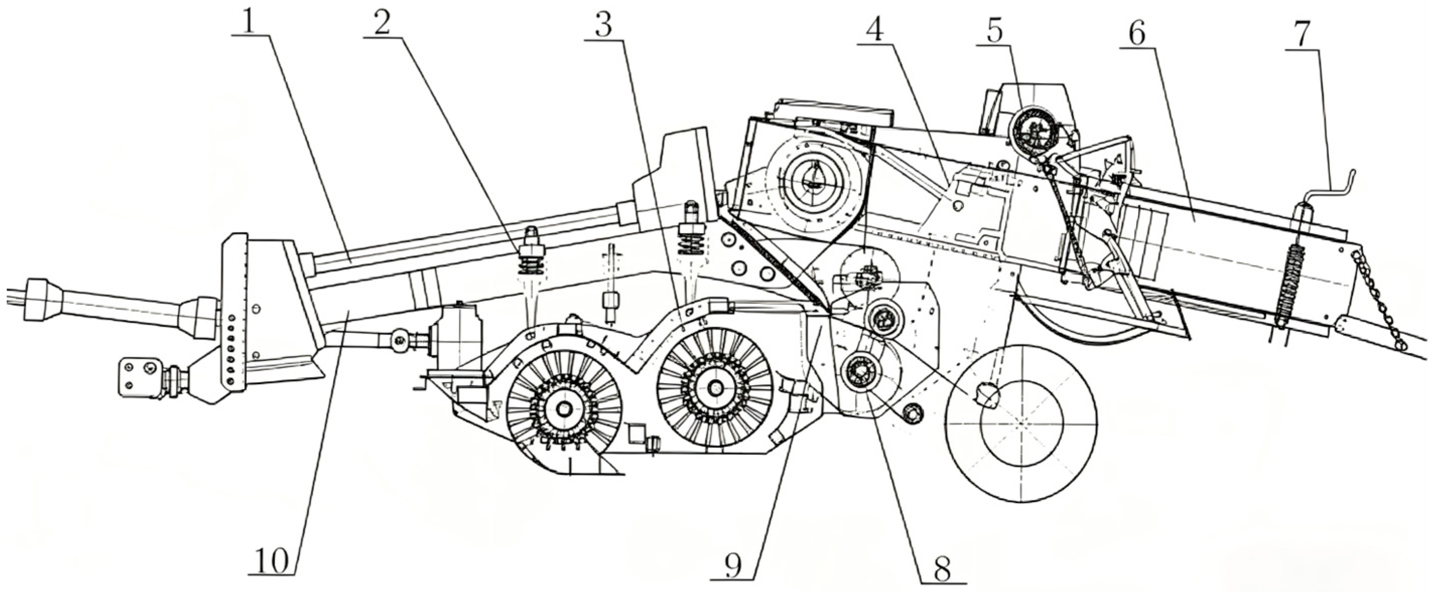
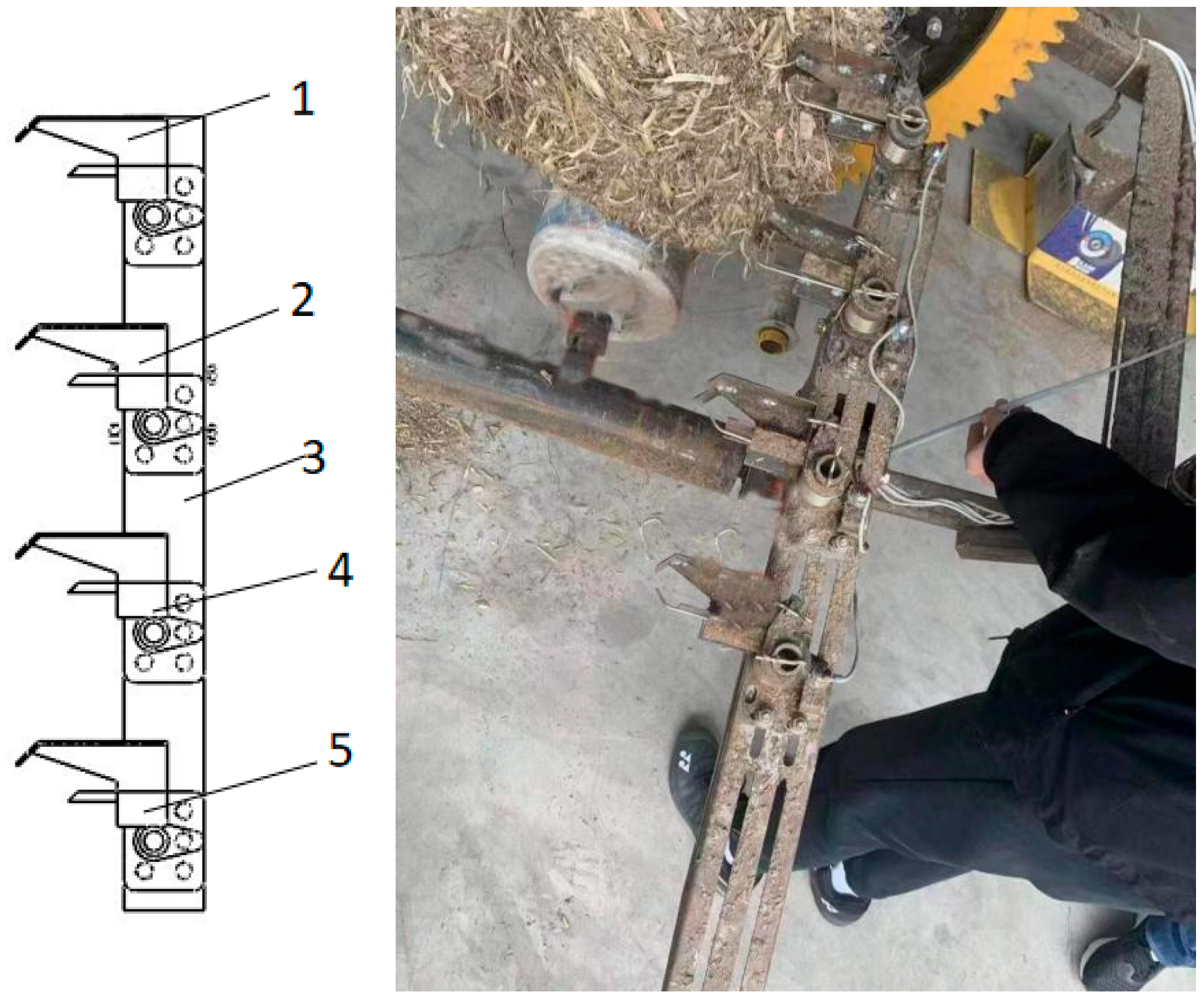
The baling chamber was responsible for compacting and shaping the fed loose straw into bales. It comprised a rectangular cavity welded from steel plates, with an internal compaction piston connected to a crank–connecting rod mechanism. Seven rollers mounted on the piston engaged with five guide rails inside the chamber, ensuring that the piston performed directional reciprocating motion. The moving and stationary blades located at the front end of the piston and the bottom of the baling chamber were manufactured from 65Mn steel, with a hardness range of HRC 54–59. The moving blade had a thickness of 10 mm, while the stationary blade was 8 mm thick, and the two worked in tandem to cut the straw. Straw deflectors installed on the side plates and the knotter base plate prevented material rebound during the piston’s return stroke, while the protruding section of the baling chamber further compacted the straw bale. The baling chamber dimensions were set to 700 × 380 × 330 mm, with a wall thickness of 5 mm. The value of 700 mm referred to the chamber length in the bale movement direction rather than the nominal piston stroke. The reciprocating frequency of the compression piston was set to 100 min
−1, as illustrated in
Figure 6.
Based on the design specifications, straw was chosen as the test material. When the moisture content is within the normal range, the bale density of straw and hay bales is measured. After conducting density tests on straw and hay bales using a square baler under standard operating conditions, the following trend was observed:
In the formula: p—compactor pressure per unit area (Pa);
—weight per unit volume of hay (kg/m3);
To convert the weight per unit volume y after compaction into parameters for the crank–connecting rod mechanism, based on the operational changes of the plunger during the compaction process, the following expressions for the compactor compression force P, crank arm tangential torque T, and crank torque M can be derived:
In the formula: P—Compactor compression force (N);
T—Crank tangential force (N);
M—Crank torque (N·m);
G—The weight of hay compressed during a single compaction cycle;
F—Compaction unit working area (m2);
α—Crank angle during hay compression by the compactor;
r—crank radius (m);
l—Connecting rod length (m);
β—Corresponding connecting rod angle when the compactor compresses hay.
The optimal straw-feeding rate for the compactor of the 9YFSG-2.2 square baler was 1.5 kg/s. Substituting this value into the formula for the mass of straw compacted in a single pass enables the calculation of the actual compression force. A comparative analysis of concentric and offset crank-slider mechanisms revealed that the offset design offered distinct advantages, including a longer slider stroke and a rapid return characteristic—this enhanced the return stroke speed, shortened the cycle time, and improved compression efficiency. Accordingly, an offset crank–connecting rod mechanism was adopted in this design.
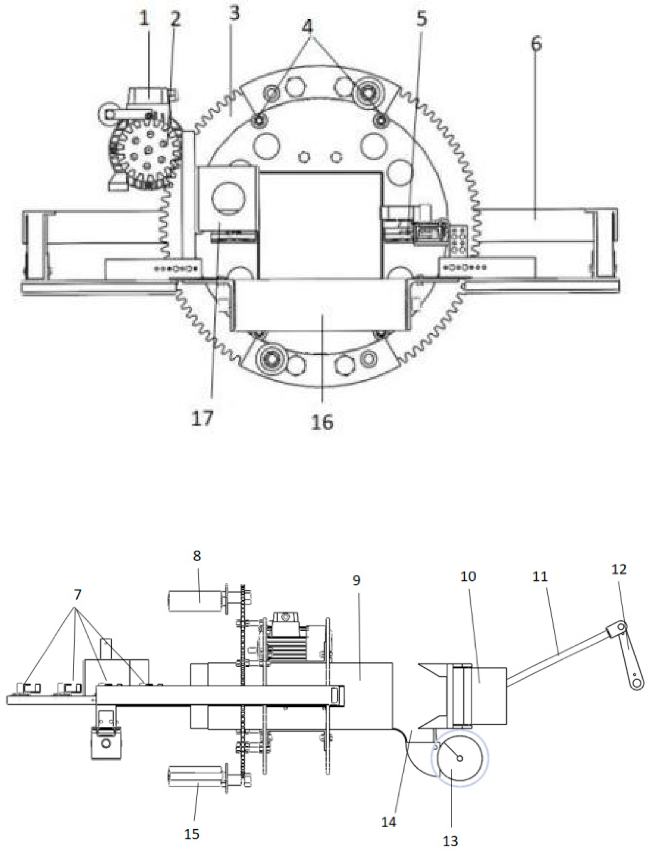
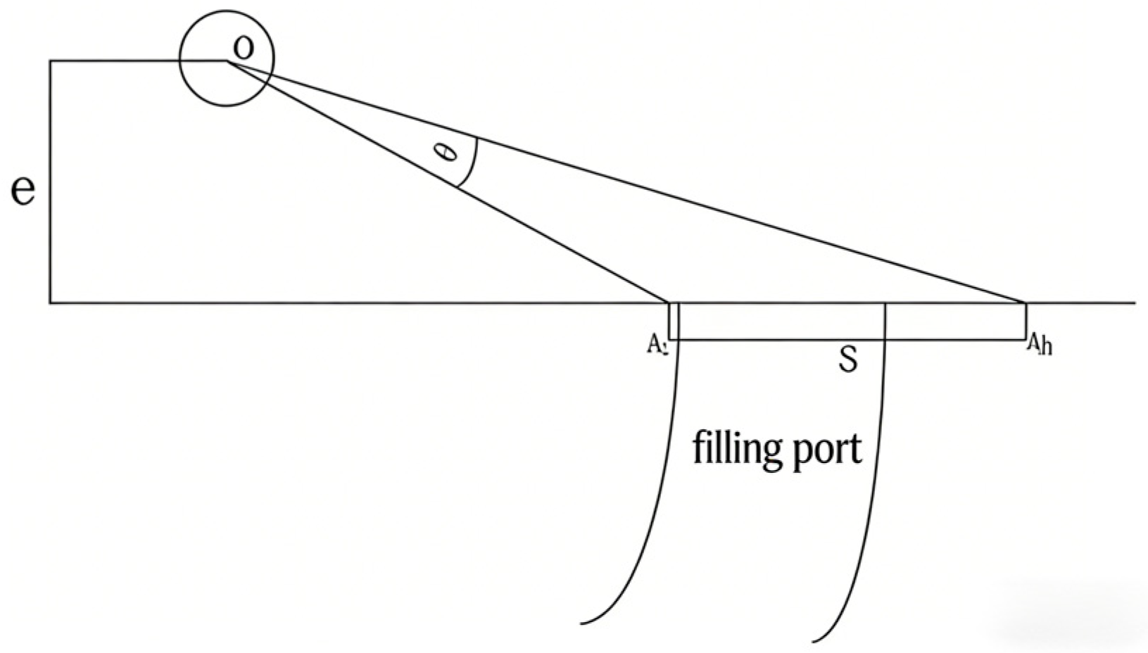
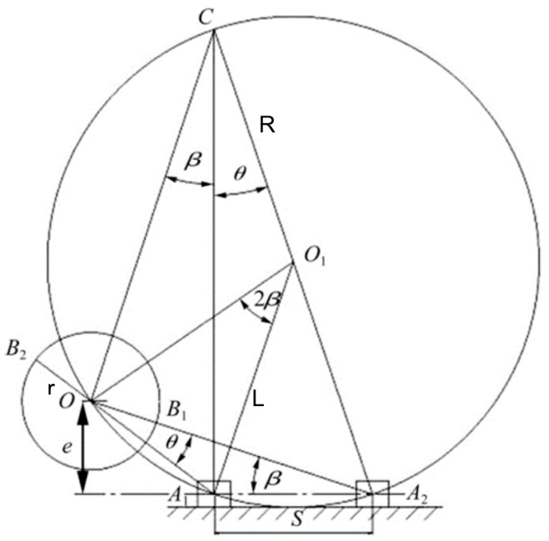
Based on the design parameters of most domestic compression mechanisms, the vertical distance between the output shaft center of the reduction gearbox and the piston’s plane of movement was set to 60 mm. According to the original machine specifications, the nominal piston stroke of the 9YFSG-2.2 baler was 550 mm. In the present study, however, the compression mechanism was redesigned using an offset crank–connecting rod configuration. Considering that the feed inlet length was 450 mm, the effective design stroke of the piston was required to exceed this value by 25–35% to satisfy the compaction requirement. Therefore, an effective design stroke of 600 mm was adopted for the kinematic calculation of the redesigned mechanism. It should also be noted that the value of 700 mm referred to the chamber length in the bale movement direction rather than the nominal piston stroke. The piston’s extreme compression position was located inside the compression chamber, while its extreme retraction position was close to the filling port of the bottom pre-compression chamber. The extreme position angle θ was set to 3°, and the structure of the compression mechanism was illustrated in
Figure 7.
In
Figure 8, points A1 and A2 represent the two extreme positions of the piston, while point O denotes the center of the reducer’s output shaft. Let the radius r of the small circle stand for the crank length. The circumscribed circle passing through points A1, A
2, and O has its center at O1 and a radius of R. Draw line A1C through point A1, perpendicular to segment A1A
2; this perpendicular intersects the large circle at point C. The geometric relationships are as follows:
From Equation (6) it follows that
From Equations (3) and (4), it follows that
Since 2β + θ = α, it follows that
From Equations (3) and (4), it follows that
After transformation, the following expression is obtained:
Substituting the known conditions e = 60, s = 600, and =3° into the above equation yields:
After rounding the lengths of the crank and connecting rod, r = 300 mm and L = 885 mm were adopted.
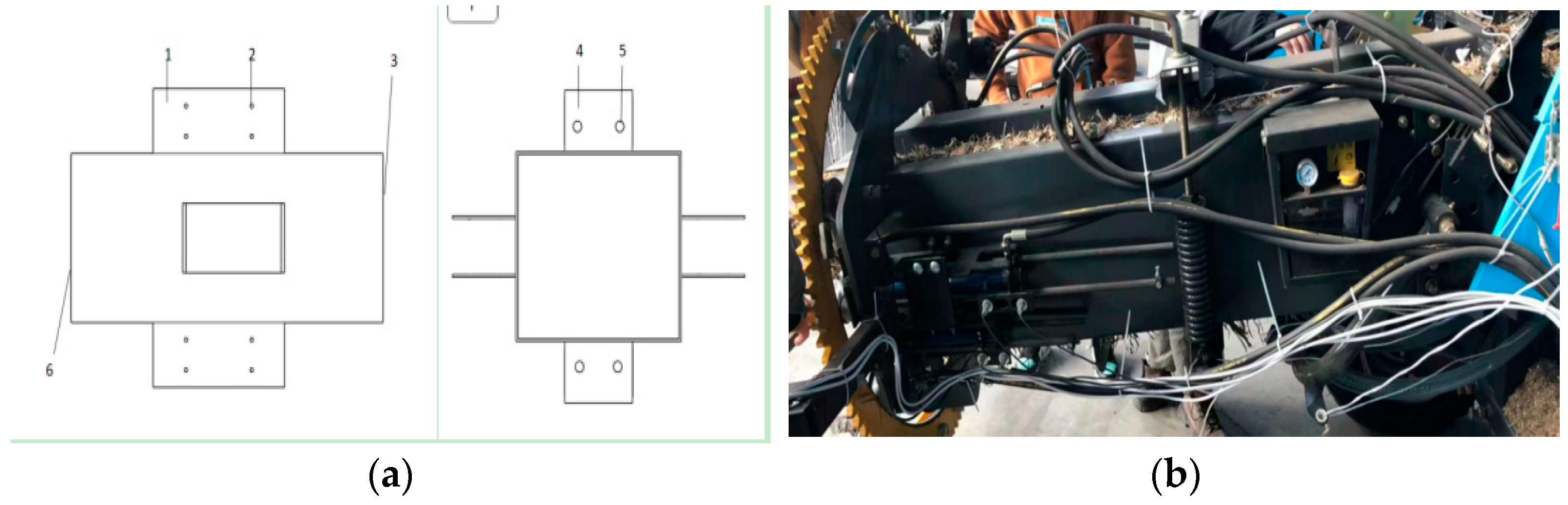
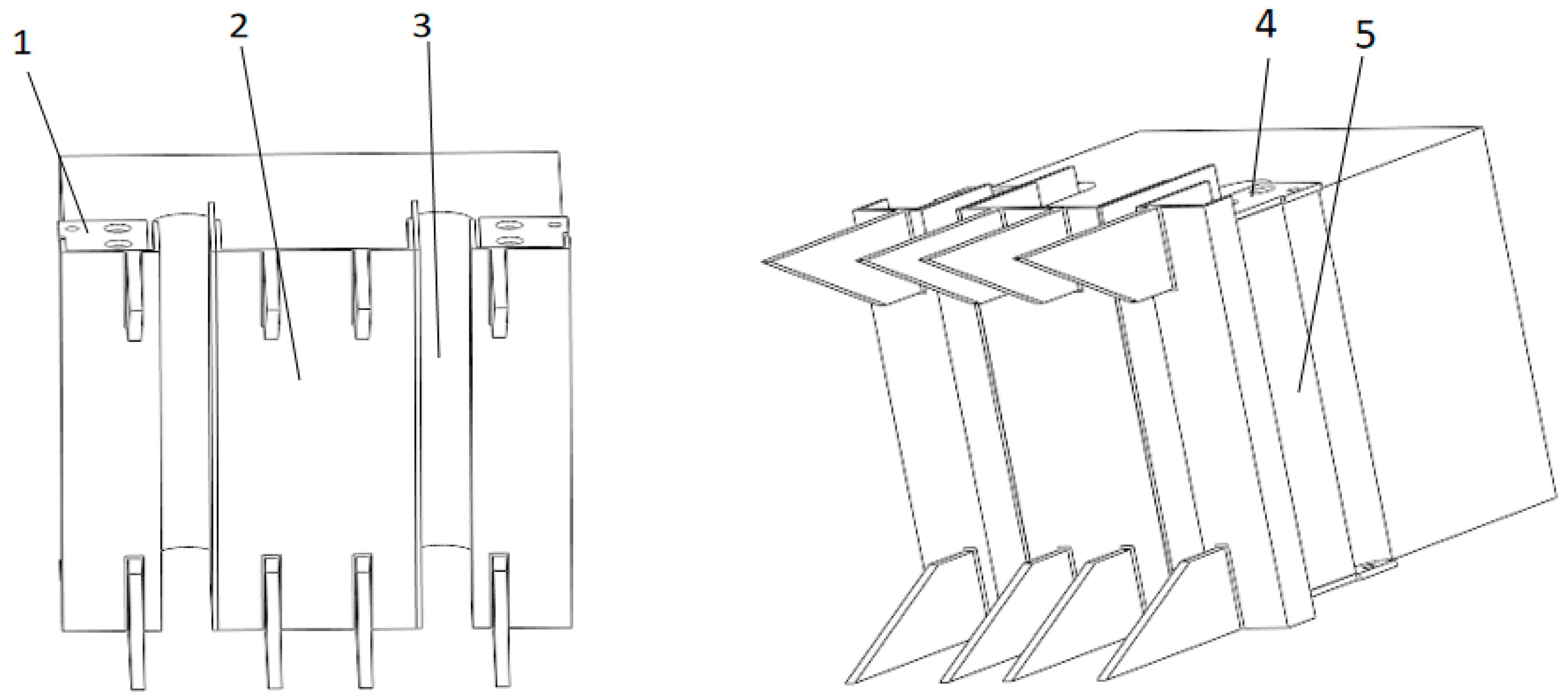
The compression piston came into direct contact with the straw and executed reciprocating compaction motion within the baling chamber. In accordance with the previously outlined structural design of the baling chamber, the piston dimensions adopted in this study are 370 mm × 290 mm. To ensure stable compaction performance, stiffening plates were attached to both sides of the piston. Three detachable cutting blades were mounted at the bottom to improve the fluidity of the straw during compaction, as illustrated in
Figure 9.
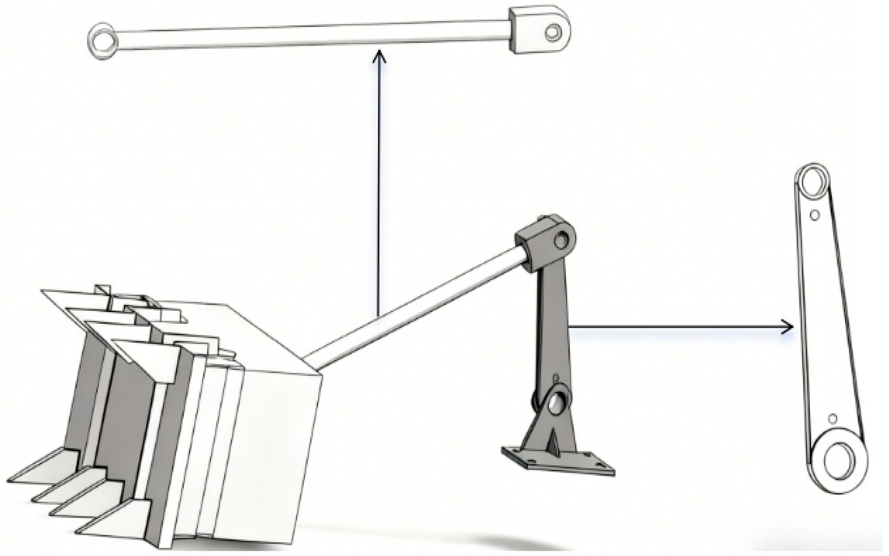
The connecting rod connected the piston to the crankshaft. Given its susceptibility to fatigue wear and deformation under periodic rotational motion, a square steel I-beam configuration was adopted. To facilitate its connection to both the crankshaft and piston, bushings were installed at both ends, with a center-to-center distance of L = 885 mm. The crankshaft ends were constrained by the connecting rod and the reducer output shaft; under torque loading, they were susceptible to fatigue. Based on domestic and international application data and theoretical calculations, the crank length was designed as r = 300 mm. Following the 3D modeling of the piston, crankshaft, and connecting rod, the components were assembled. The schematic diagram of the entire compression mechanism and the crankshaft-connecting rod assembly was illustrated in
Figure 10.