Article

Analysis and Mitigation of Vibrations in Front Loader Mechanisms Using Hydraulic Suspension Systems

Department of Agricultural Engineering and Safety, Faculty of Engineering, Vytautas Magnus University, Studentu str. 15, LT-53361 Kaunas, Lithuania
*
Author to whom correspondence should be addressed.
AgriEngineering 2025, 7(9), 276; https://doi.org/10.3390/agriengineering7090276
Submission received: 4 July 2025 / Revised: 8 August 2025 / Accepted: 20 August 2025 / Published: 27 August 2025
(This article belongs to the Collection Research Progress of Agricultural Machinery Testing)

Abstract

Agricultural tractors possess front loaders that are employed for the handling and transportation of materials, but are exposed to mechanical vibrations and shocks from ground undulations and sudden variations in the load. These vibrations are harmful to the durability of the parts, the comfort of the driver, and the longevity of the machine. In this current study, the performance of the hydraulic accumulator to mitigate such vibrations for a Foton 904 wheeled tractor equipped with a TZ10C-824 front loader is studied. Vibration measurements were taken by an experimental Brüel & Kjær 3050-A040 analyzer under various loading configurations (no loading, 180 kg, and 312 kg), with or without a 1.4 L, 50-bar nitrogen gas-charged Fox Opera Mi Italy hydraulic accumulator. Results reveal that maximum accelerations were as much as 6.24 m·s−2 without an accumulator during testing of a 312 kg load, whereas they were extremely low at 2.66 m·s−2 when the accumulator was activated. Frequency-domain analysis verified that the main vibrations were within the range of 3–4 Hz, with FFT peak amplitudes dropping from 5.6 m·s−2 to 2.4 m·s−2 upon the accumulator’s operation. The observations verify the effectiveness of the accumulator in vibration intensity reduction, absence of high-frequency shock loads, and ride comfort, along with structural safety improvement. The study provides a solid platform for further enhancement in vibration control techniques for agricultural machines and loader system design.

1. Introduction

Front loaders are being used more and more in construction and agriculture, which emphasizes the need for better vibration control to increase operator comfort and durability. The analysis of vibrations impacting front loader components and the assessment of hydraulic accumulators’ ability to reduce oscillations are the main areas of the current study. To eliminate tractor-induced oscillations during movement, lessen impact loads on the loader frame, and enhance operator comfort generally, more research is necessary to develop an integrated suspension system within the front loader itself [1,2].
Mechanical suspension systems using springs and rubber mounts are widely used due to their simplicity and robustness, though they provide limited adaptability to varying loads and terrains [3,4]. Hydraulic suspension systems offer adjustable damping and improved vibration isolation, enhancing operator comfort and component protection, but at increased cost and maintenance complexity [5,6]. Active and semi-active suspensions employ sensors and actuators to dynamically counteract vibrations, showing superior performance in a range of conditions; however, their complexity and cost currently restrict widespread use [7,8]. Additionally, operator seat suspension systems are standard to reduce whole-body vibration exposure and operator fatigue, but do not mitigate structural vibrations [9]. Among these, hydraulic and active suspension technologies demonstrate promising application prospects for advanced tractors, balancing vibration control efficacy and operational adaptability [10].
The vertically induced vibrations of tractors, largely due to the elastic tire–soil interactions and the absence of complete suspension damping systems, significantly affect the performance of the vehicles and the comfort of the operators. Such vibrations are affected by factors such as forward speed and tire air pressure, and insufficient damping could cause operator fatigue and wear and tear. Apart from the mechanical and operational conditions, the nature of the terrain also plays a role in shaping the frequency and amplitude of vibrations transmitted to the tractor driver. Sláma et al. [11] investigated timber forwarding tractor exposure to whole-body vibration (WBV) and found that irregular forest floors, among other terrain conditions, raised WBV magnitudes considerably.
Also, during the indicial movement of the slinky/trailer in the vertical (up-and-down) direction relative to the tractor, the front loader attachment can serve as a kind of kinetic energy “accumulator”, soaking up the kind of energy that would have resulted in oscillation. Tires alone would not be enough to absorb these vibrations if the tractor or front loader is not equipped with enough suspension components, and something else needs to give so that there is not as much driver fatigue [12,13].
The research was conducted on off-highway front loaders examined with an active vibration-damping system that uses electro-hydraulic controls with feedback for acceleration and pressure, which shows that the oscillations were successfully minimized, improving ride comfort and decreasing mechanical strain on loader components. It also reveals that the cabin vibration directly responds to worker safety, comfort, and mechanical output. Due to the high cost and performance limitation of the active ride control system, the use of active electro-hydraulic alternatives is suggested. Considering this, their non-linearity and dynamic response must be studied to determine if they fulfill the desired performance. To eradicate this issue, research suggests a novel hydraulic system topology that links the increased lift actuators to different modes for ride control, which include a full-size wheel loader to test two active control systems that use pressure and acceleration response. With this facility, the vibration level that was on par with the commercial alternatives gives 10% additional improvement [14,15].
In this research, magnetorheological actuators (MRAs) for active suspension are used in heavy machinery and agricultural tractors’ active suspension systems, which display effective high force and frequency performances that can be utilized to effectively reduce vibrations and enhance operator comfort [15]. The feasibility of a hydrostatic Magnetorheological (MR) clutch-driven actuator remotely placed on a suspended frame showed that the low inertia allowed the blockade output force bandwidth of 20 Hz with peak output force overcoming 15 kN [15]. Due to the phenomenon of the non-linear dynamic response of the electro-hydraulic system, without additional components have been replaced by boom lift actuators on a full-size wheel loader, which uses pressure and acceleration measurement to suppress cabin vibration by 10% [15].
Without an effective suspension on the tractor frame, heavy loads travel over rough terrain by compressing and rebounding the tires, which changes the wheel axle-to-ground distance. This causes increased wear on tires, particularly on hard ground, as it creates kinematic mismatches in the gearbox of the tractor. Some of the shock energy is also taken up by the loader’s metal frame, which eventually leads to fractures and breaks [16]. By minimizing vibrations, the study assessed the effectiveness of various tractor suspension systems on operator comfort. Axle suspensions, cabin suspensions, and cabin rubber mounts on uneven terrain were compared by researchers using half-tractor simulation models. According to the results, vertical cabin vibrations decreased by more than 50% when axle and cabin suspension were combined, and by up to 78.3% when cabin suspension was applied at both ends. Axle suspension was best around 3 Hz, while cabin suspension was best at all frequencies. From the results of the study, agricultural tractors with cabin suspension systems had much more comfortable rides [17].
Another frequent issue with front loader-equipped tractors is vertical oscillation when driving on roads. One of the solutions is the addition of suspension to the front axle, but it is complex and costly to design. Another solution is the addition of suspension to the front loader itself, which eliminates tractor oscillations when driving, reduces impact loads on the loader frame, and improves operator comfort [15].
Although numerous studies have been performed on active vibration dampening devices and magnetorheological actuators (MRAs), these are typically compounded with electro-hydraulic control circuits, sensor feedback loops, and are power- and cost-prohibitive. The hydraulic accumulator, however, is a passive vibration reduction device that possesses simpler integration, significantly less operational expense, and no power or complex controls external to it. Whereas MRAs are capable of dynamic damping over a wide frequency range, they tend to be complex to tune and are not best suited to budget-restricted agricultural use [18].
This research comparatively examines the application of a hydraulic accumulator in a real-world working front loader configuration, presenting a simpler yet efficient vibration reduction alternative. To our knowledge, no previous work has compared and quantitatively investigated the performance of this system under real load conditions in time and frequency domains with industrial-grade sensors. The relevance is drawn from introducing an efficient, low-cost solution experimentally validated through extensive experimental analysis under real farming operating conditions. The objective of the research is to investigate oscillations and vibrations in the tractor’s frame by comparing the improved and unimproved front loader.

2. Materials and Methods

The research aimed to investigate the influence of different load conditions and hydraulic accumulator adjustments on the vibrations induced by a tractor-mounted front loader. The tractor involved in the research was a Foton 904 (new in 2008) with a factory-installed TZ10C-824 front loader. The tractor had approximately 2580 operating motor hours (now 2645 h) when tested, on which a Fox Opera Mi Italy hydraulic accumulator produced by FOX Via S. Francesco d’Assisi, 43, 20073 Opera MI, Italy and sourced from Pasvalio Agrodileris, Lithuania. was installed. The accumulator was filled with nitrogen at a pressure of 50 bar and connected to the loader hydraulic system via a valve. The setup allowed the accumulator to be turned on or off during the experiment, offering a controlled way of examining its effect on vibration reduction. The same operator performed all experiments in order to ensure consistency and eliminate the role of human-related variability. Additionally, the tractor was fixed during testing because the experiments were drop-load impacts, not movement under field conditions.
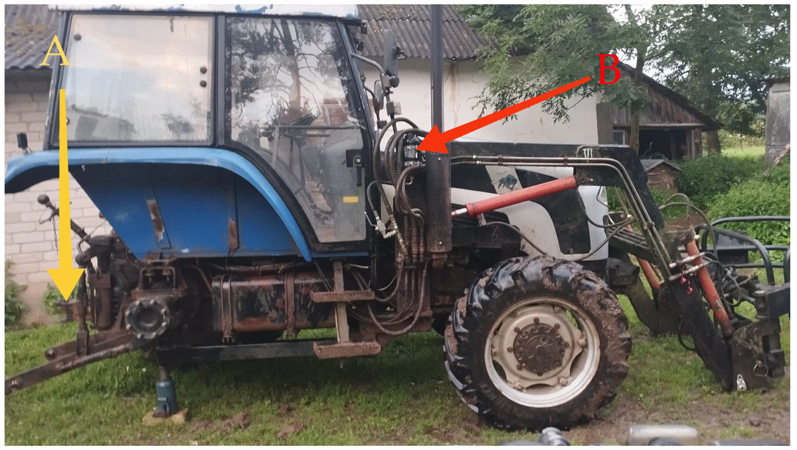
Figure 1 illustrates the Foton 904 tractor manufactured at Shandong, China, by “Foton Heavy Industries”, and how the hydraulic accumulator was integrated into the loader system. The accumulator served to perhaps remove vibration by reducing the vibration of the loader, especially when it was subject to varying load conditions. The study utilized Brüel & Kjær (Figure 1) 3050-A040 vibration measuring instruments, which comply with ISO 10816/ISO 20816—Mechanical vibration [19]—Evaluation of machine vibration measurement standard. The specific B&K 4526 vibration accelerometer (Figure 1) was employed to capture the vibration readings during experimentation. B&K 4526 was used to measure the vibrations at various points on the loader system and the tractor. The reason is that this sensor measures high-frequency vibrations, and the sensitivity of the sensor makes it most suitable for the fine analysis required in this study [20,21]. Furthermore, Figure 2 illustrates the location of the accumulator and hitch.
The vibration-damping effect due to the hydraulic accumulator can be explained by its own dynamic nature, which is a function of pre-charged nitrogen gas compressibility in the accumulator chamber. When, for example, there is a sudden impact or pressure surge on the front loader—e.g., load descent shock or impact from terrain—the hydraulic fluid compresses the nitrogen gas, which absorbs the energy temporarily. This procedure reduces the maximum force imparted to the tractor frame. In expansion back to equilibrium, the energy stored is released in a controlled manner, thereby damping out the oscillations. This passive energy absorption mechanism and delayed release functions as though it were a spring-damper system, damping out the amplitude and frequency content of the vibration. Compared to rigid hydraulic systems, the compressible medium prevents abrupt pressure jumps, and thus smoother system dynamics and improved ride comfort. The damping capacity is higher for low frequencies (around 3–4 Hz), which also corresponds to the natural vibration modes of the tractor frame, as also confirmed by our FFT analysis results.
Table 1 provides a detailed description of the B&K 4526 sensor specifications. Its frequency range of 0.3–8000 Hz enables it to capture a wide vibration frequency range, required for the analysis of the varied mechanical behavior of the tractor and loader under various loads. Its sensitivity of 10 mV:ms−2 ensures detection of even the minute vibrations for proper vibration analysis.
The experiment involved using 180 kg and 312 kg weights, a 3.2 m ruler, and a manometer. The tire pressures were taken before the experiment to determine whether they were in the correct range. The front tire was adjusted to 2.5 bar, and the rear tire was adjusted to 1.8 bar. This is due to tire pressure potentially affecting overall vibration behavior during the experiment. The engine speed of the tractor was kept constant at 700 rpm. This speed was used to simulate normal working conditions for front loader operations, such as lifting and lowering loads using the tractor in a stationary state or moving at slow speeds. For the Foton 904 tractor, 700 rpm hydraulic power is sufficient to run the front loader and obtain stable controlled motion with less vibration caused by the engine. It also represents average field usage where operators prefer precise loader control over mobility speed. Selecting the medium engine speed also removes confounding causes of vibration from the engine to allow for measured vibrations to be produced mostly by loader movement and load impact. The ruler was pushed into the ground to a depth of 0.2 m, with the reference point at a height of 1 m, in a way that the distance and height were kept constant throughout the experiment.
As shown in Figure 3, the vibration sensor was positioned on the rear hitch of the tractor in a vertical position. This location was selected because it forms part of the structural frame and therefore can measure the overall vibration transmitted by the frame from the front loader, especially impact loading. The hitch, also located out of the engine compartment, minimizes interference from engine-generated vibrations so that measured data more accurately reflect vibrations caused by loader use. While additional checks at other locations were taken to cross-validate, the hitch was the primary reference point for all tests due to its consistency and accessibility. The previous work has identified that rear frame vibrations bear a direct correlation with both structural safety concerns and the total dynamic response of the machine, pointing to it as an ideal measure of operational vibration intensity and comfort considerations [18,21].
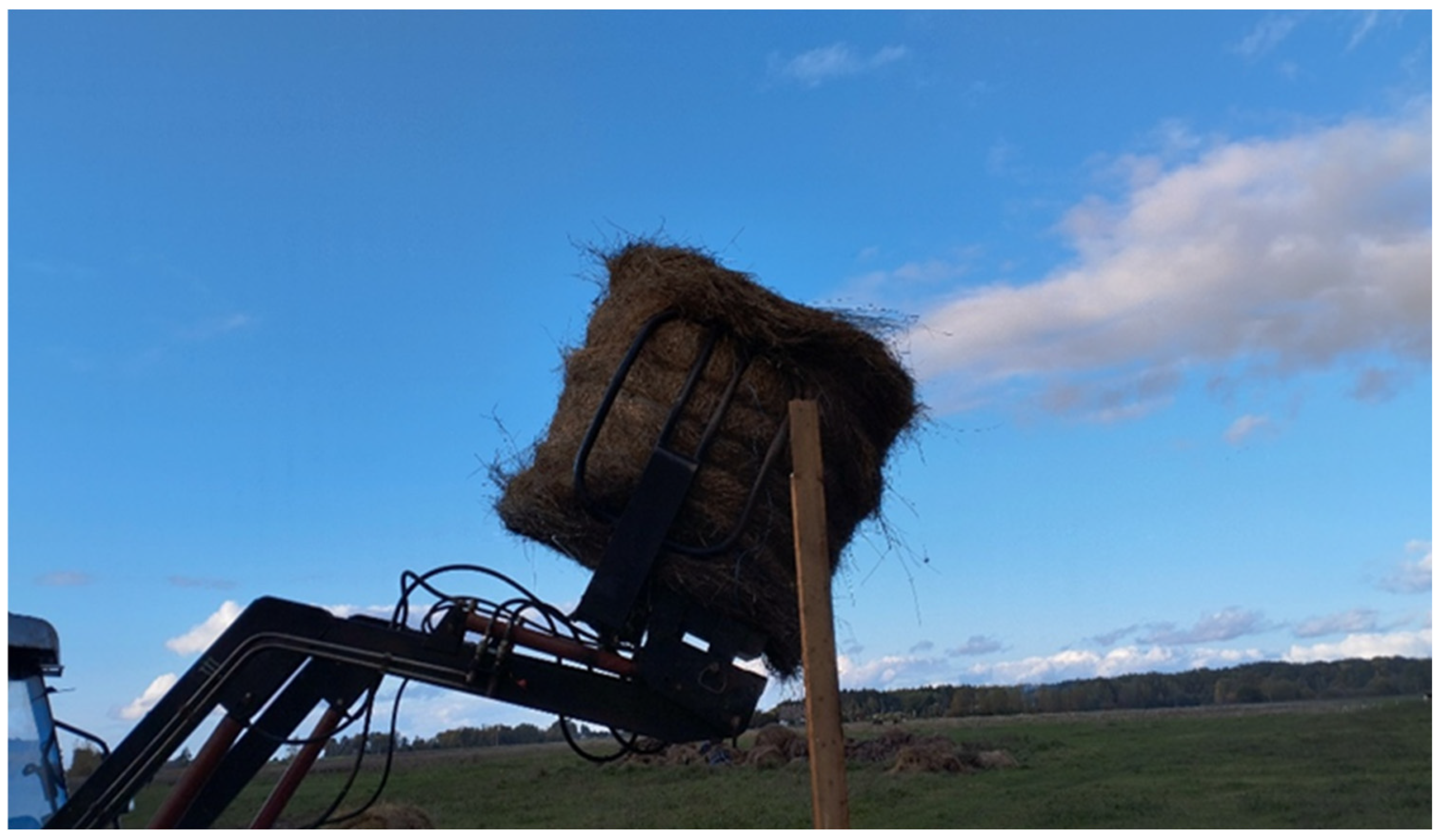
In the test, the loader was raised to 3 m and subsequently to 1 m in mimicking the normal working cycle of the loader. During the process, the distributor valve was opened fully to allow the loader to descend quickly. The quick descent was intended to simulate field working conditions where loaders are subjected to quick unloading of materials. As the loader finished the cycle, the vibration level at several points was recorded. Of particular interest was the point where the loader came to a complete stop and the rear end of the tractor shifted when the pressure was released by the load. Figure 4 illustrates a load being lifted by the loader to a height of 3 m, which is an integral part of the experiment. The cycle of lifting is critical in generating vibrations, which are sensed by the sensors attached to the tractor.
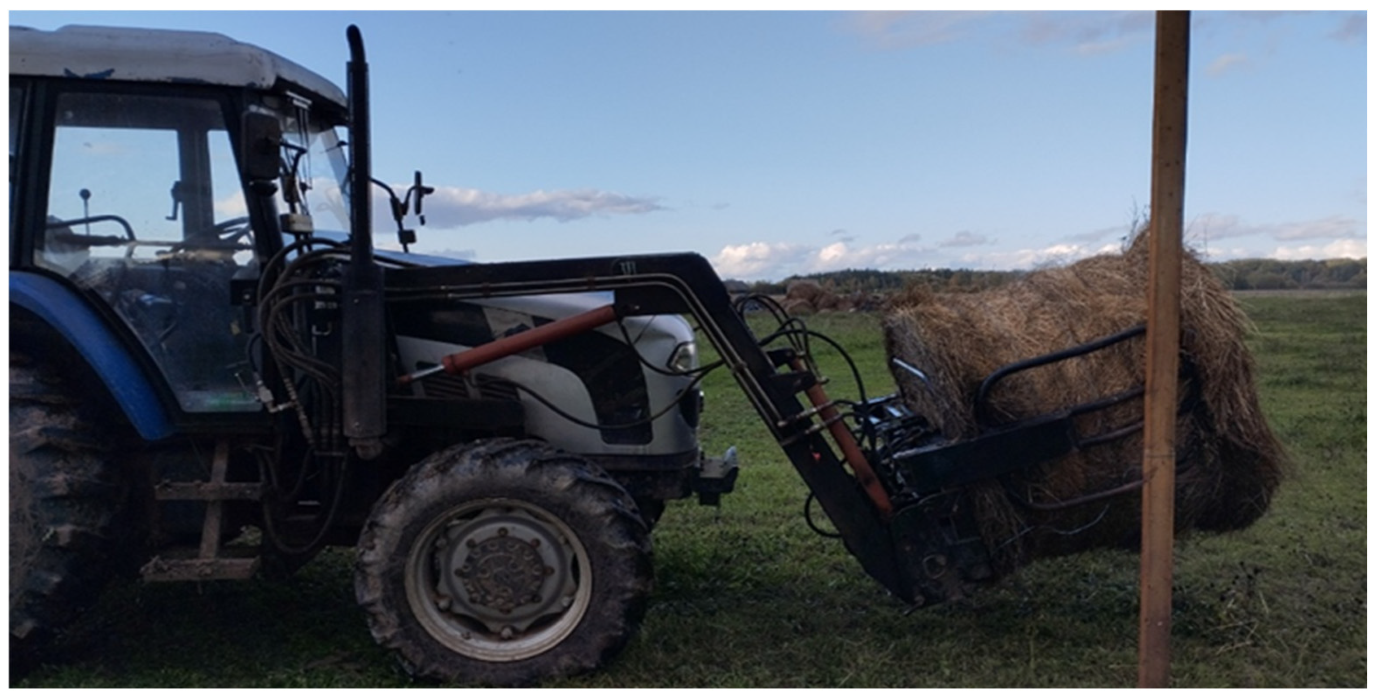
As shown in Figure 5, the quick drop of the load to the level of 1 m induces vibrations that are necessary for the experiment. The study explores how the vibrations differ depending on the load and how the hydraulic accumulator operates.
The testing was performed under three conditions of loading: a light load with only bale clamps, 180 kg, and 312 kg. Two configurations of the hydraulic accumulator were tested for each load level: the accumulator off and on. Six tests were performed for each setting—three with the accumulator off and three with the accumulator on. This setup enabled a comprehensive comparison of the impact of the hydraulic accumulator on vibration mitigation under different load levels.
The time series signal from an accelerometer is obtained, and then the RMS acceleration, peak acceleration, crest factor, and FFT are obtained by Formula [22].
Root Mean Square (RMS) acceleration represents the power content in the signal obtained by Equation (1) as follows:
a R M S = 1 N i = 1 1 v x i 2
where xi is the sample of the signal and N is the total number of samples.
Peak acceleration indicates the highest amplitude of the vibration signal as follows:
a P e a k = max x t
where x(t) is the vibration signal (acceleration in m/s2) recorded over time t.
Crest factor (for shock detection) is the ratio of peak acceleration to RMS acceleration. It is used in shock detection as follows:
C F = a P e a k a R M S
Also, FFT (Fast Fourier Transform) converts a time-domain signal x(t) into frequency components X(f) using the numerical formula [15,21]. FFT X[k], if x[n] is a discrete signal of length N, the Discrete Fourier Transform (DFT) is given by Equation (4).
x k = n = 0 N 1 n · j 2 π N k n   f o r   k = 0 ,   1 ,   . . ,   N 1
where
  • X[k] is the complex FFT output at frequency bin k
  • |X[k]|: amplitude spectrum
  • Fk = (k fs)/N is the corresponding frequency in Hz
  • Fs: is the sampling frequency in Hz
  • N: is the number of samples in the time-domain signal
Sampling frequency (Fs) was 2000 Hz, and the impact event was recorded for 10 s. Therefore, 20,000 samples per event were utilized for FFT analysis. The data from the accelerometer was exported in an Excel sheet, and the statistical data, peak acceleration, and time-domain and frequency-domain analysis and plotting were accomplished with a Python script (version 3.11.9) and Excel plots (Office package version 2021).

3. Results and Discussions

3.1. Peak Acceleration Measurement During Impact

The time taken for the loader to descend under no load was measured, and the equipment was calibrated to this time interval. The test was then conducted by the procedure described. The peak frame acceleration of the tractor upon impact was measured when the descending loader was suddenly stopped. The results are shown in Table 2. Loader descending time (10 s) for calibration gives a consistent operating condition for all the tests. Brüel & Kjær’s data acquisition system digitizes the analog signal of measured acceleration data and displays it with the Pulse analyzer software type 3580, and the data is transferred to an Excel file. The data acquisition system also includes a low-pass filter as a part of anti-aliasing and signal conditioning. The measurement of peak acceleration, due to a sudden stop, to assess the impact load on the tractor frame, is performed.
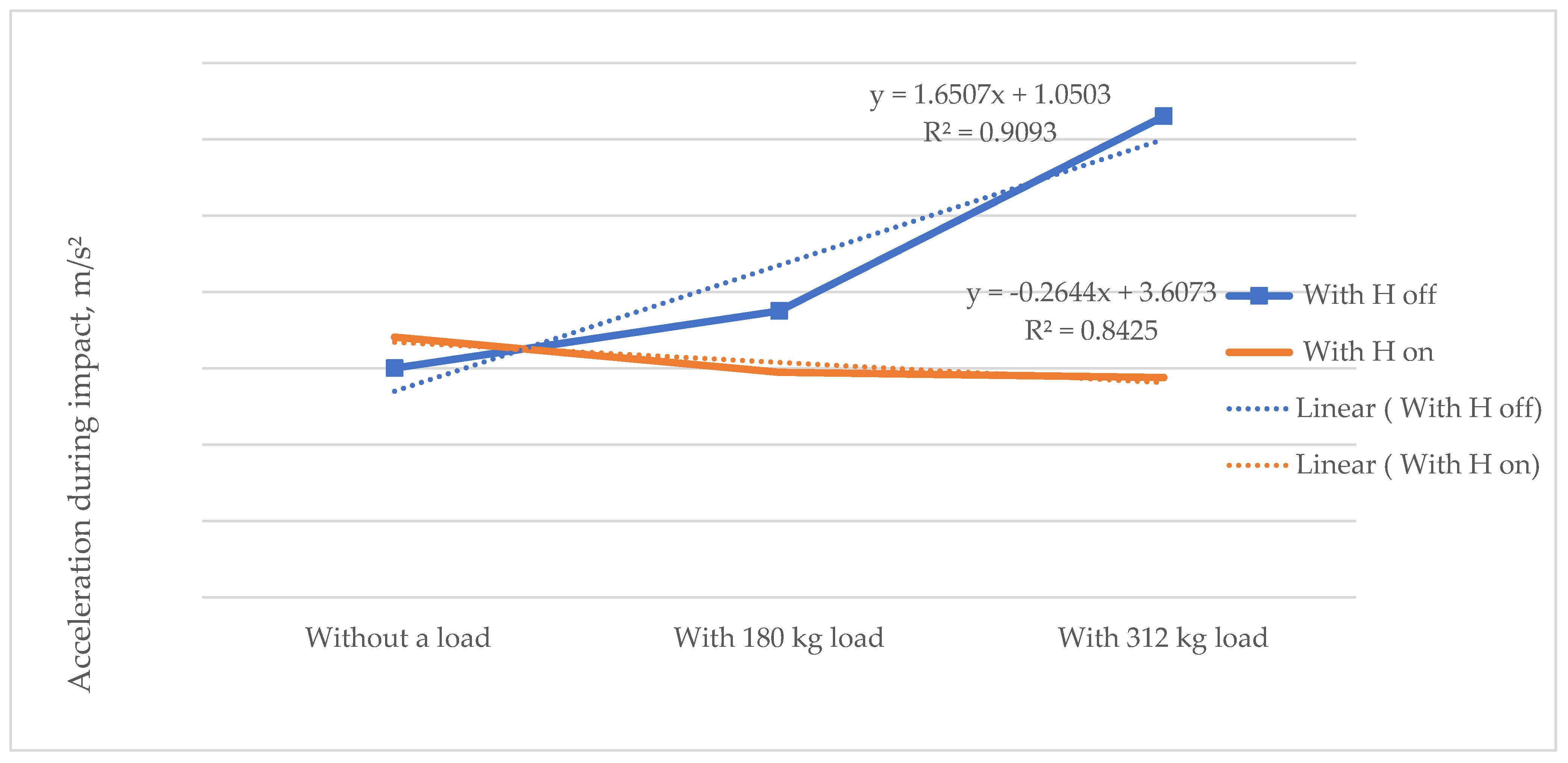
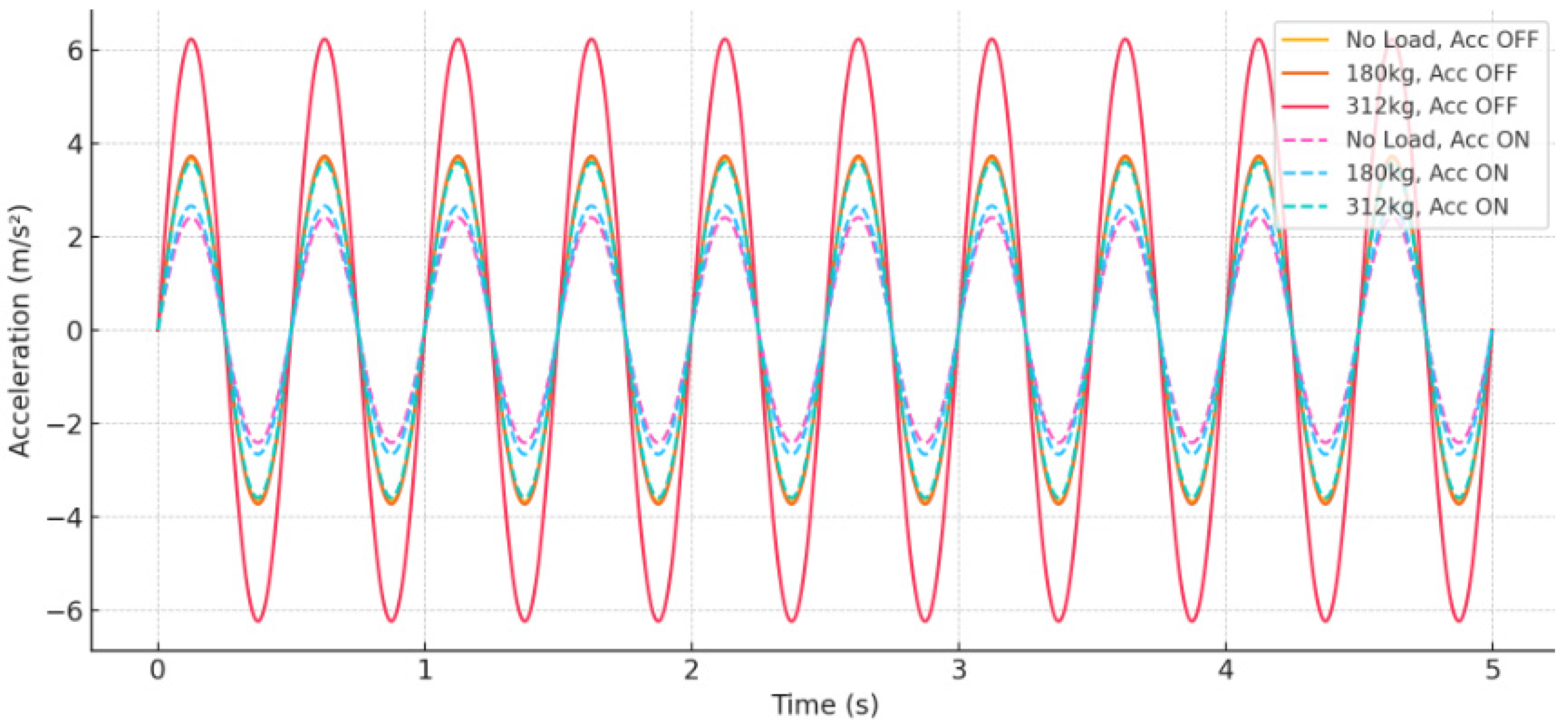
The principal results are given in Table 2. When the hydraulic accumulator is off (H off), the peak acceleration value increases with load. Mean values of 3.68 m/s2 for no load, 3.73 m/s2 for 180 kg load, and 6.24 m/s2 for 312 kg load were recorded. When the hydraulic accumulator is on (H on), peak acceleration values are much smaller and also increase with increasing load. The average values of 2.41 m/s2 under no load, 2.66 m/s2 under 180 kg load, and 3.59 m/s2 under 312 kg load were noted. The comparative peak acceleration value was significantly less under the heaviest load (312 kg), from 6.24 m/s2 to 3.54 m/s2, when H is off and on. Standard deviation and variability showed higher values relative to the average value, indicating some variability in repeated measurements or transient dynamic effects during impact. It may be due to a slight inconsistency in the loader descent dynamic or measurement noise, while considering the general trends remains clear. The student coefficient and error value show the statistical treatment of the data, showcasing the confidence in the reliability of the results despite the variability. Errors are also minimal compared to the magnitude of accelerations.
Further, the results were presented in a graph (Figure 6). As the figure indicates, in the absence of the hydraulic accumulator, the maximum tractor frame acceleration at impact grows exponentially as the load mass increases. Therefore, with the rise in the load, the impact on the frame also rises. Alternatively, with the accumulator working, the peak tractor frame acceleration at impact changes little. This indicates that the loaded loader, while the accumulator is working, does not transfer a greater shock to the tractor frame and driver than the unloaded loader. This shows that the hydraulic accumulator performs very well in damping the shock force transmitted to the tractor frame and operator when working.

3.2. Time-Domain Vibration Signal Analysis

Figure 7 shows a time-domain vibration signal under different loads, with and without the function of a hydraulic accumulator. With increased load (from no load to 312 kg), peak acceleration also increases substantially when the accumulator is de-energized—i.e., increased mechanical shock transferred to the tractor frame. As a point of comparison, during accumulator operation, the vibration amplitude is much smaller and relatively consistent at diverse loads, proving that the hydraulic accumulator dampens the impact forces effectively.

3.3. Frequency-Domain Analysis (FFT) of Vibration Signal

FFT analysis was also performed on the rear frame acceleration measurement of the Foton 904 tractor experiencing impact events under different loading and accumulator situations. The vibration amplitude at the most significant frequency band (~3–4 Hz) under different loads and hydraulic accumulator situations is depicted by the frequency-domain analysis graph [23,24]. As will be noted from Table 3, in the absence of the hydraulic accumulator, amplitude rises exponentially with load, with higher vibration energy and more intense impacts. For instance, when the load was 312 kg, the amplitude was 5.6 m/s2. Whereas, when the accumulator was activated, amplitude values are significantly low at all loads, below 2.5 m/s2, even at full load. This indicates the efficacy of the accumulator for vibration damping, structural stress reduction, and operator exposure.
The controlling frequency always arises at around 3–4 Hz as it relates to the natural mode of vibration usually present in the tractor frame. Such findings validate the role of an accumulator in dampening the amplitude and magnitude of shock loads, enhancing structural strength and comfort for drivers.
The findings verified that the amplitude of impact vibration is considerably less with a hydraulic accumulator under any load. Peak acceleration was reduced up to 57% by the use of a hydraulic accumulator compared to the no-accumulator situation when the load was 312 kg, efficiently preventing shock transmission through the tractor frame.
The finding is in accordance with previous work in the field but offers novel verification in real front-loader configurations with time- and frequency-domain analysis. For instance, Sun et al. [25] minimized suspensions for tractor seat and reported 50% reductions in whole-body vibration (WBV) exposure, but did so for operator seats—not frame or structural damping. Our findings provide a complementary observation by showing dramatic vibration control at the frame level.
Additionally, Zindulka et al [26] simulated a single-DOF tractor seat suspension incorporating an MR damper and implemented three comfort-based controllers—two-state skyhook (SH-2), skyhook linear approximation (SH-L), and acceleration-driven damper (ADD); with a fast MR damper (1.5 ms response), seat-transmitted vibration (standard deviation of seat acceleration) was reduced by 26.8% (SH-2), 29.5% (SH-L), and 29.2% (ADD) compared to the optimal passive suspension. Yet, our passive accumulator system operates efficiently within a range of 3–4 Hz (the dominant frequency of oscillation for the tractor frame) without sensors, actuators, or an external power source—making it very retrofitable and field-friendly.
In structural vibration attenuation, Kim et al. [14] conducted a safety analysis of front-end loaders and pointed out that utilization of structural reinforcement reduces shock loads. However, the study did not provide vibration amplitudes in quantitative form. Our experimental FFT results show directly that passive accumulation reduces frame shock loads by quantifiable values at dominant frequencies. Han et al. [17] researched the influence of cabin and axle suspension systems and achieved up to 78% vibration reduction in certain configurations. Substantial redesigns are required for such arrangements. Our solution is a less complicated option with significant damping capability and low installation complexity.
The most pertinent to terrain vibration is the research conducted by Šlama et al. [11], where WBV exposure during timber forwarding operations was measured. These results showed crests in vibrations of over 4.10 m·s−2 at low frequencies caused by irregular terrain. The highest frequency vibrations (1–5 Hz) observed in their work were very close to the 3–4 Hz peak amplitudes in our FFT analysis. This tells us that hydraulic accumulators could effectively counteract shocks from terrain in real operating conditions, despite our research having been conducted using controlled loading.
Unlike Zhou et al. [6], who examined hydraulic suspension applications in agriculture and commented on their complexity, our work is a more practicable passive system for shock isolation without any modifications to drive trains or feedback mechanisms.
The passive hydraulic accumulator system represents a highly cost-saving vibration reduction option for tractors. With an estimated cost of installation of EUR 300–EUR 400, including accumulator, fittings, and labor, it is significantly lower than active or semi-active systems at over EUR 2000 and requiring complex integration. It is particularly pertinent that numerous farmers, especially from developing nations, cannot afford to purchase new tractors or advanced equipment. Therefore, retrofitting existing machinery with a low-maintenance, uncomplicated accumulator provides a cost-efficient and scalable solution for promoting ride comfort and mechanical stress reduction in agricultural production.
Finally, while certain studies bear evidence of effective vibration decreases through active or semi-active systems, they rely on the supply of energy, advanced controllers, or changes to basic machine design. Our research verifies the implementation of a low-cost, passive hydraulic accumulator as a structurally integrated, commercially viable solution for the damping of mechanical shock in tractors with front loaders. The system performance at the 3–4 Hz band is in line with simulated and observed field vibration profiles, providing a tested alternative for overall agricultural use.

4. Conclusions

The test data conclusively demonstrate that the hydraulic accumulator substantially enhances peak acceleration and vibration transmitted to the tractor frame in impact accidents at various levels of load. Without the accumulator, peak accelerations increased substantially with load, reaching a peak of 6.24 m/s2 in the maximum load (312 kg). On the other hand, with the accumulator energized, peak accelerations were never higher, showing a reduction of up to 57%, and were quite consistent even under escalating load. Time-domain vibration waveforms and frequency-domain FFT analysis also showed that the accumulator effectively dampens mechanical shocks primarily occurring around the natural vibration frequency of 3–4 Hz. This passive hydraulic system improves structural safety through lowered frame stress and operator comfort through reduction in whole-body vibration exposure. Compared to more complex active or semi-active suspension systems, the hydraulic accumulator offers a robust, energy-independent, and cost-effective solution appropriate for retrofitting in farm machinery, especially in harsh field environments. Future work could lengthen test duration, quantify operator comfort subjectively, and compare to other suspension technologies to properly certify long-term benefits and real-world usability.

Author Contributions

Conceptualization, E.J. and J.B.; methodology, E.J. and S.B.; software, S.B. and J.B.; validation, E.J. and S.B.; formal analysis, S.B. and J.B.; investigation, J.B. and S.B.; resources, E.J.; data curation, E.J. and S.B.; writing—original draft preparation, S.B.; writing—review and editing, S.B., E.J., and J.B.; visualization, E.J. and S.B.; supervision, E.J.; project administration, E.J.; funding acquisition, E.J. All authors have read and agreed to the published version of the manuscript.

Funding

This research received no external funding.

Data Availability Statement

Data will be made available on reasonable request.

Acknowledgments

The authors have reviewed and edited the output and take full responsibility for the content of this publication.

Conflicts of Interest

The authors declare no conflicts of interest.

References

  1. Williamson, C.; Lee, S.; Ivantysynova, M. Active Vibration Damping for an Off-Road Vehicle with Displacement Controlled Actuators. Int. J. Fluid Power 2009, 10, 5–16. Available online: https://journals.riverpublishers.com/index.php/IJFP/article/view/491/259 (accessed on 25 April 2025). [CrossRef]
  2. Liu, C.; Gu, J.; Du, X.; Yang, L.; Du, Y.; Mao, E. A Vibration Reduction Control Method for Tractor Rear Hydraulic Hitch Based on Pressure Feedback. Agriculture 2023, 13, 1546. [Google Scholar] [CrossRef]
  3. Yang, Z.; Zhang, W.; Chen, X. Design and Performance of Mechanical Suspension Systems in Agricultural Tractors. J. Agric. Eng. 2021, 37, 45–53. [Google Scholar]
  4. Kumar, R.; Singh, P. Evaluation of Rubber Mount Systems for Vibration Reduction in Farm Machinery. Biosyst. Eng. 2020, 192, 56–67. [Google Scholar] [CrossRef]
  5. Li, H.; Wang, J.; Zhao, Y. Hydraulic Damping Technologies for Front Loader Vibration Control: A Review. Mech. Syst. Signal Process. 2022, 170, 108756. [Google Scholar] [CrossRef]
  6. Zhou, T.; Liu, Q.; Huang, X. Application of Hydraulic Suspensions in Agricultural Vehicles: Advantages and Challenges. Comput. Electron. Agric. 2023, 198, 107123. [Google Scholar] [CrossRef]
  7. Yu, M.; Evangelou, S.A.; Dini, D. Advances in Active Suspension Control for Off-Road Vehicles. Engineering 2024, 33, 160–177. [Google Scholar] [CrossRef]
  8. Chen, Y.; Li, X.; Zhao, Z. Semi-Active Suspension Systems: A Review of Control Strategies and Applications in Agricultural Machinery. Sensors 2020, 20, 3442. [Google Scholar] [CrossRef]
  9. European Machinery Directive 2006/42/EC. Whole-Body Vibration Exposure and Operator Comfort in Agricultural Machinery. Health and Safety Executive 2019. Available online: https://eur-lex.europa.eu/legal-content/EN/TXT/?uri=CELEX%3A02019R1243-20230112 (accessed on 25 April 2025).
  10. Johnson, M.; Patel, S. Emerging Trends in Suspension Systems for Agricultural Tractors. Biosyst. Eng. 2024, 215, 25–38. [Google Scholar] [CrossRef]
  11. Šlama, H.; Daněk, P.; Šrédl, K.; Novák, O. Magnitude of WBV Affecting the Tractor with a Timber Trailer Operator during Individual Timber Forwarding Operations. South-East. Eur. For. 2022, 16, 25–33. [Google Scholar]
  12. Brunetti, J.; D’Ambrogio, W.; Fregolent, A. Analysis of the Vibrations of Operators’ Seats in Agricultural Machinery Using Dynamic Substructuring. Appl. Sci. 2021, 11, 4749. [Google Scholar] [CrossRef]
  13. Barač, Ž.; Plaščak, I.; Jurić, T.; Marković, M. The Impact of Vibrations on the Hand–Arm System and Body of Agricultural Tractor Operators in Relation to Operational Parameters, Approach: Analytical Hierarchical Process (AHP). AgriEngineering 2025, 7, 56. [Google Scholar] [CrossRef]
  14. Kim, J.-H.; Gim, D.-H.; Nam, J.-S. Experimental Structural Safety Analysis of Front-End Loader of Agricultural Tractor. Agriculture 2024, 14, 947. [Google Scholar] [CrossRef]
  15. Riccardo, M.; Andrea, V. An Active Oscillation Reduction Method for Off-Highway Front Loaders. Proceedings of the Institution of Mechanical Engineers, Part D. J. Automob. Eng. 2023, 237, 1015–1031. [Google Scholar] [CrossRef]
  16. Mallette, G.; Gauthier, C.-É.; Hemmatian, M.; Denis, J.; Plante, J.-S. Design and Experimental Assessment of a Vibration Control System Driven by Low Inertia Hydrostatic Magnetorheological Actuators for Heavy Equipment. Actuators 2023, 12, 407. [Google Scholar] [CrossRef]
  17. Han, G.; Kim, K.-D.; Ahn, D.-V.; Park, Y.-J. Comparative Analysis of Tractor Ride Vibration According to Suspension System Configuration. J. Biosyst. Eng. 2023, 48, 69–78. [Google Scholar] [CrossRef]
  18. Masa’id, A.; Lenggana, B.W.; Ubaidillah, U.; Susilo, D.D.; Choi, S.-B. A Review on Vibration Control Strategies Using Magnetorheological Materials Actuators: Application Perspective. Actuators 2023, 12, 113. [Google Scholar] [CrossRef]
  19. ISO 20816-1:2016; Mechanical Vibration—Measurement and Evaluation of Machine Vibration—Part 1: General Guidelines. ISO: Geneva, Switzerland, 2016.
  20. Brüel & Kjær. Type 4526 High-Temperature CCLD Accelerometer Specifications. Brüel & Kjær Sound & Vibration Measurement A/S. Available online: https://www.bksv.com/en/transducers/vibration/accelerometers/ccld-iepe/4526 (accessed on 30 May 2025).
  21. Li, X.; Ma, Y.; Zhang, J.; Wang, H. Influence of Sensor Placement on Vibration Measurement Accuracy in Agricultural Machinery. Sensors 2021, 21, 4567. [Google Scholar] [CrossRef]
  22. Inman, D.J. Engineering Vibration, 4th ed.; Pearson Education: Upper Saddle River, NJ, USA, 2014; Volume 36–41, pp. 58–65. [Google Scholar]
  23. Almady, S.S.; Al-Janobi, A.A.; Marey, S.A.; Al-Sager, S.M.; Aboukarima, A.M.; Gaddal, Y.H. Establishment of a Measuring Unit Based on Arduino Board for Recording Vibrations on an Agricultural Tractor during Tillage Process. Meas. Control. 2024. [Google Scholar] [CrossRef]
  24. Xu, G.; Zhu, S.-H.; Nie, X.-T.; He, L. Natural Frequencies Calculation for Vibrating Systems of Tractors Made in China. J. Vib. Shock. 2014, 33, 157–161. [Google Scholar]
  25. Sun, X.; Liu, Y.; Zhang, L.; Bai, W.; Zhang, Q.; Zhang, Y. Optimal Design of a Tractor Seat Suspension System Based on Multi-Objective Optimization. J. Low Freq. Noise Vib. Act. Control. 2024, 43, 403–420. [Google Scholar] [CrossRef]
  26. Zindulka, M.; Strecker, Z.; Jeniš, F. Semiactive Seat Suspension for Agricultural Machines. In Proceedings of the 26th International Conference Engineering Mechanics 2020, Brno, Czech Republic, 24–25 November 2020; Brno University of Technology, Institute of Solid Mechanics, Mechatronics and Biomechanics: Brno, Czech Republic, 2020; pp. 548–551. [Google Scholar] [CrossRef]
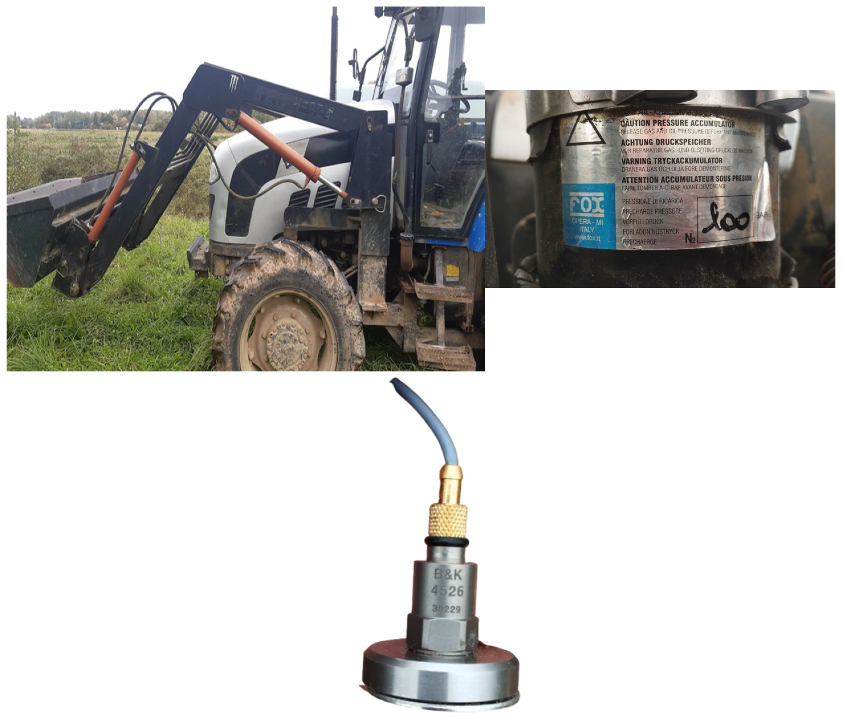
Figure 1. Foton 904 tractor with attached hydraulic accumulator and sensor B&K 4526 vibration accelerometer.
Agriengineering 07 00276 g001
Figure 2. Location of hydraulic accumulator (marked as B in red) and location of sensor on hitch (marked as A in yellow).
Agriengineering 07 00276 g002
Figure 3. Sensor fixed to the hitch: (a) location on the tractor, (b) attachment to the hitch.
Agriengineering 07 00276 g003
Figure 4. Loader raises the load to a 3-m height.
Agriengineering 07 00276 g004
Figure 5. Loader drops the load to the start position (1 m).
Agriengineering 07 00276 g005
Figure 6. Acceleration graph of the frame during impact under different conditions.
Agriengineering 07 00276 g006
Figure 7. Time-domain vibration signal under different load and accumulator conditions.
Agriengineering 07 00276 g007
Table 1. B&K 4526 sensor specifications.
ParameterValue
Frequency Range0.3–8000 Hz
Temperature−54–180 °C
Weight5 g
Sensitivity10 mV:ms−2
Connector10–32 UNF
Signal OutputCCLD
Table 2. Tractor frame peak accelerations during impact under different loading and hydraulic accumulator conditions.
ConditionAcceleration of Impact, m/s2AverageStandard DeviationA. Standard DeviationStudent Coefficient (t)Error
1st Take2nd Take3rd Take
Without load, H off2.4183.3503.2383.000.5090.2944.3031.264
Without load, H on3.6803.0833.4643.410.3030.1754.3030.752
With 180 kg load, H off3.7233.6853.8433.750.0820.0474.3030.205
With 180 kg load, H on3.5392.9392.3622.950.5880.3404.3031.464
With 312 kg load, H off6.2415.4047.2656.300.9320.5384.3032.315
With 312 kg load, H on2.6613.0782.9012.880.2090.1214.3030.520
Table 3. Amplitude at dominant frequency at primary impact.
Test ConditionFFT Amplitude at 3–4 Hz (m/s2)Hydraulic (H) State
Without load2.5off
Without load1.8on
With 180 kg load3.2off
With 180 kg load2.1on
With 312 kg load5.6off
With 312 kg load2.4On
Disclaimer/Publisher’s Note: The statements, opinions and data contained in all publications are solely those of the individual author(s) and contributor(s) and not of MDPI and/or the editor(s). MDPI and/or the editor(s) disclaim responsibility for any injury to people or property resulting from any ideas, methods, instructions or products referred to in the content.