1. Introduction
To ensure the care of forests, it is necessary to make them sufficiently accessible by forest roads. Unfavorable terrain conditions and the relatively large weight of wood place high demands on the technical level of forest roads. Forest roads help to ensure the timely fulfillment of economic tasks related to logging, forest protection, cultivation, transport of harvested wood and temporary storage. Therefore, it is necessary to improve, reconstruct and maintain their high technical condition. Currently, road cutters-stone crushers are used for the construction and reconstruction of forest roads. The basic working tool are hammers, or round shanks of various shapes, composed of a body and a tip. The tools are exposed to difficult working conditions caused by the heterogeneous composition of the working environment, which mainly consists of hard rocks of various shapes and sizes. They are subject to a strong abrasive environment, which often leads to damage, up to the complete destruction of the functional part of the tool. There are frequent tool changes, which increases the working time and increase the cost of fuel, and the purchase of new tools. For these reasons, it is necessary to deal with the possibility of increasing their lifetime.
Currently, conical picks are the essential tools used in cutterheads of many working machines in various industries [
1,
2,
3]. They are used in underground and opencast mining and often in construction, tunneling, road construction and maintenance. The service life of conical picks depends on their working conditions, where the most important is the abrasiveness of the mined rocks. In harsh conditions, these tools work for only a few hours, and changing them is time-consuming and requires the machine to be stopped. Hence results in a decrease in efficiency and higher costs of the process.
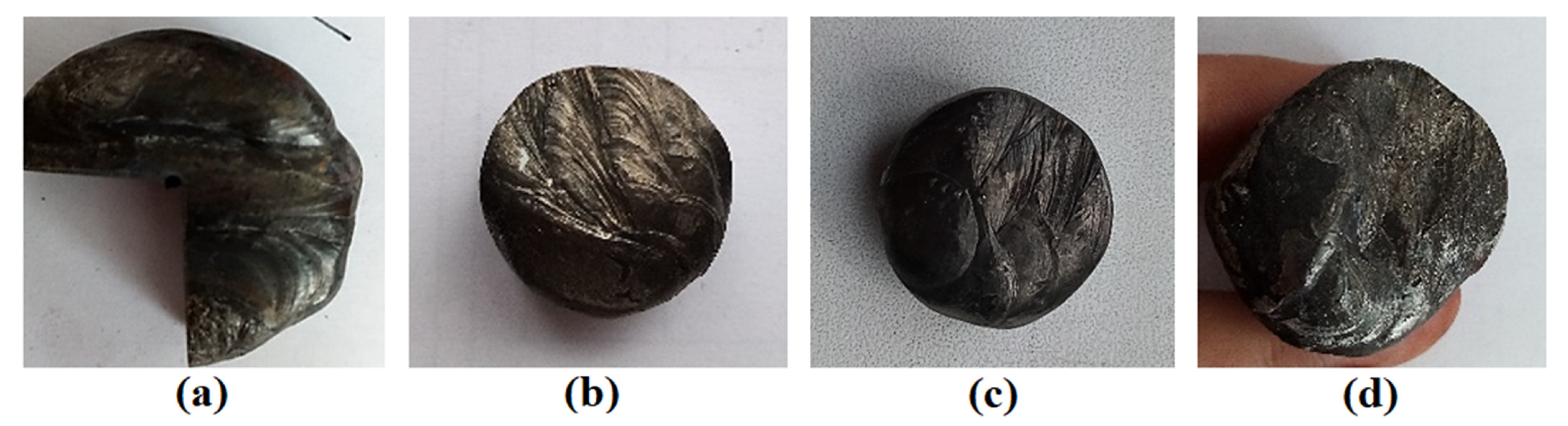
Figure 1 shows an example of worn conical picks.
Figure 1a,c have asymmetrical forms, and the rest have symmetrical forms. Typical cutterheads are usually equipped with about 40–60, but their number exceeds a hundred for longer drums. Therefore, their durability is crucial, and it has an economic dimension.
Conical picks are often the subject of research and development works in many universities and research centers worldwide. Research is often conducted to increase the durability of knives operating in abrasive conditions, i.e., to develop tools resistant to abrasive wear. There are many examples of such studies. In one of the articles, tools with a body protected with wear-resistant coatings and sintered carbide rings were tested [
4]. In another, the mechanism of abrasive wear was studied, and tool wear prediction was proposed [
5]. In the next one, the possibility of supporting the mining process was investigated [
6]. Tests were also carried out for the cemented carbides themselves [
7]. Complete tools [
8] and entire cutting heads [
9] are often tested. The following articles concerned the adaptation of modern tools and machines to difficult conditions [
10,
11] and the use of disc tools as an alternative to conical picks [
12,
13]. Testing the quality of tools was also discussed to facilitate the selection of the best offer in public tenders [
14].
Figure 1.
Worn conical picks [
14]: (
a,
c) asymmetrical forms; (
b,
d,
e) symmetrical forms.
Figure 1.
Worn conical picks [
14]: (
a,
c) asymmetrical forms; (
b,
d,
e) symmetrical forms.
A typical conical pick has a characteristic shape. It is made in the form of a solid revolution (
Figure 2a). It consists of a working part (cutting part) 2 and a gripping part 3 (mounted in pick holder). The working part is reinforced with a sintered carbide insert 1. Conical picks are mounted in pick holders with special locks. The characteristic shape of the body and the mounting method allows free rotation of picks. The rotation of picks results in even wear of the working part and the insert. Thanks to the even wear, the picks shorten but retain their shape and can properly carry out the mining process. The body of the pick and the gripping part are made of steel characterized by high impact strength (usually U > 25 Jcm
−2) and very high tensile strength (R
m > 1000 MPa), as well as resistance to abrasive wear. The working part should have a hardness of at least 45 HRC, while the hardness of the gripping part should be in the range of 25 HRC–35 HRC [
15]. Depending on working conditions, various types of steel are applied, such as 14NC11, 41Cr4, 40NiCr6, 36CRNIMo4 or 34CRMo4 (designations according to EN 10084). In addition, the knives are subjected to heat treatment to increase their hardness and, thus, the abrasion resistance of the surface layer. Additional wear-resistant layers are made of stellites or cemented carbides, usually based on cobalt, nickel and iron. These layers are made by hardfacing with electrodes. The hardness of the coatings may exceed 60 HRC [
15].
The inserts are made by sintering. Typically, cemented carbides for rock mining consist of wolfram carbide WC (89–95%), and the rest is cobalt C, a matrix. Wolfram carbide is hard and wear-resistant but brittle. Cobalt is the bonding phase and increases the toughness of the insert. The hardness of the cemented carbides exceeds 1050 HV30. Nowadays, sometimes users also require a specific grain size of WC. The inserts are soldered in sockets of working parts.
In addition to the material parameters discussed above, geometric and kinematic parameters also determine the correct mining course. Below is the range of parameters of typically tapered cutters used for mining rock and other materials. The markings are shown in
Figure 2b.
Usually, these parameters amount to the following [
15]:
Length of pick: Lc = 120 mm–250 mm;
Length of working part: Lr = 40 mm–100 mm;
Gripping part diameter: du = ϕ20 mm–ϕ40 mm;
Flange diameter: dk = ϕ45 mm–ϕ70 mm;
Mounting method: Seger, HERT, expanding or friction ring;
Insert diameter: dw = ϕ10 mm–ϕ25 mm;
Insert height: hw = 14 mm–40 mm;
Tip angle: 2βu = 80°–95° (more than 95° for ballistic shape);
Yip shape: conical, multi-conical, ballistic, hat-shaped.
Many models of picks are available on the market, differing in material and geometrical parameters, shape and assembly method. This results in the existence of more than two hundred models of picks. Shape and size depend on the type of machine, which is related to the type of cutting material and environment (
Figure 3a–d).
Basic equipment for the creation, modification and reconstruction of forest roads includes adapters as additional equipment for UKT (universal wheeled tractor). Alternatively, they are designed as adapters for various special machines or mounted on hydraulic manipulators (
Figure 4).
Since the tools work in a highly abrasive environment, they are subject to a lot of abrasive wear. Abrasive wear occurs whenever a solid object is loaded with material particles of equal or greater hardness [
16]. The abrasive wear mechanism is a complex process in the context of many factors. The intensity of these factors depends on the operating conditions of the environment in which these components and tools work. Furthermore, there are the operating parameters of the machines and the material properties of the contact surfaces [
17]. There are several methods for increasing the resistance to abrasive wear. One such method is to apply additional materials to the exposed parts of the functional surfaces of the tools. Hardfacing is a commonly used method to improve the surface properties of agricultural tools, mining components and soil preparation equipment, among others [
18]. In order to choose a suitable hardfacing material, it is necessary to know not only the basic material of the tool but also the environment in which the tool works.
2. Materials and Methods
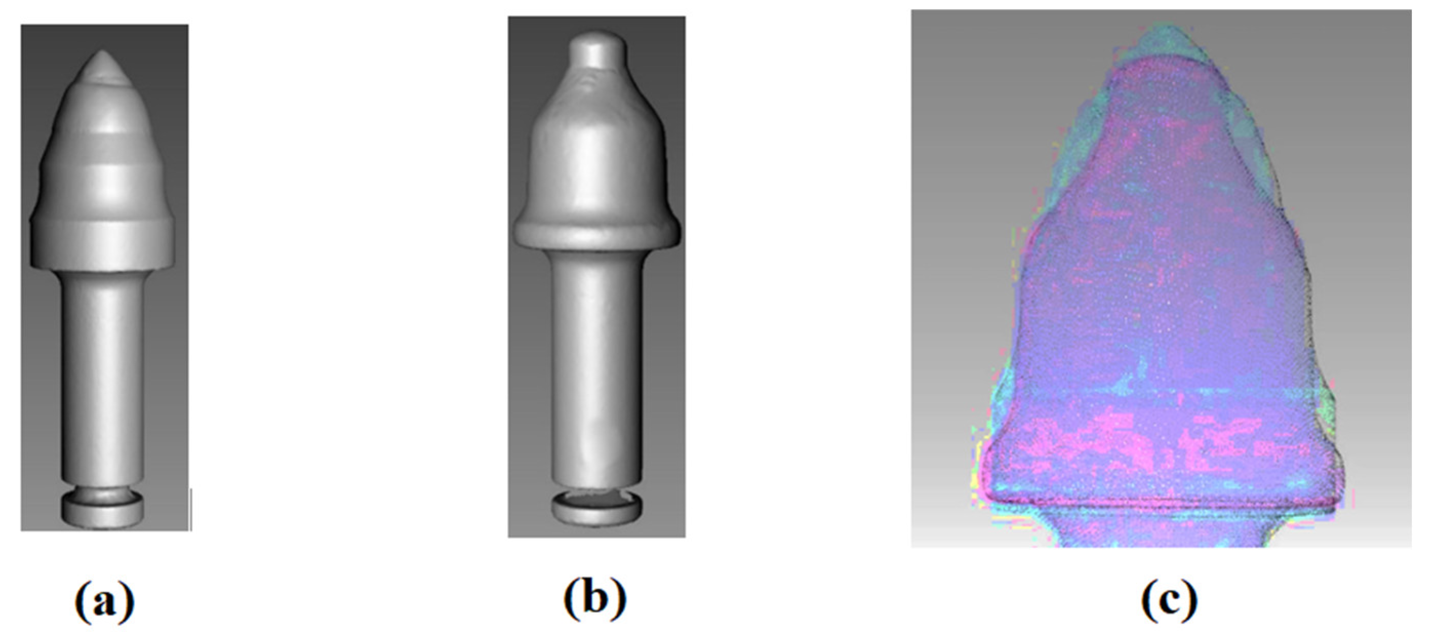
The functional surfaces of the tool are the surfaces that are most involved in stone crushing and are exposed to strong abrasion and abrasive wear. In
Figure 5, we see a new (unused) tool (
Figure 5a) and a worn tool (
Figure 5b) that has been used in continuous operation for approximately three months. We can see that there is a change in the shape and loss of material of the wolfram carbide (WC) tip and the area under the WC tip. From this, we can conclude that these surfaces are most involved in stone crushing. The tool had to be taken out of service after a high rate of wear.
We used the visualization method to detect the wear of the working tool. With this method, a 3D image (scan) of the new (
Figure 6a) and the used (
Figure 6b) working tool was performed. After subsequently overlaying them, we see that there was a change in the shape of the WC tip and a loss of material below the carbide tip (
Figure 6c). This also confirmed the defined functional areas of the working tool.
As it was not known what material the tools were made of, a chemical analysis was carried out. Based on the chemical analysis performed, we found that the tool is made of 38Mn6 manganese steel [
19]. The chemical composition of this steel is in
Table 1.
The working tools of a road milling machine are subject to a lot of abrasive wear and need to be replaced frequently. Their frequent replacement causes technical and economic problems. For this reason, it is necessary to devise ways of increasing the lifetime of such tools. On the basis of practical experience, as well as the results of some authors [
20,
21], we have decided to hardfacing by welding the functional surfaces of the working tools of road milling machines.
To perform the experiment, we chose the following four types of electrodes:
Hard deposit created by the ABRADUR 58 electrode [
22];
Hard deposit created by the E DUR 600 electrode [
23];
Hard deposit created by the UTP DUR 600 electrode [
24];
Hard deposit created by the WEARTHRODE 55 HD (OK 84.58) electrode [
25].
The samples were made by a certified person for welding in the company ZOŠ Zvolen (Railway Repair and Engineering Works Zvolen). Hardfacing by welding was carried out manually by electric arc at welding position PA.
Sample 1 (
Figure 7a) was made from the hard deposit formed with the ABRADUR 58 electrode. ABRADUR 58 is an electrode from SIJ ELECTRODE JESENICE, which creates a hard layer with extreme resistance to abrasion and a moderate impact. The hard deposit is made of chrome steel. Depending on the carbon and chromium content, the hard deposit has ferritic, austenitic-martensitic and semi-ferritic structures. It is mainly used for the hardsurfacing by the welding of crushers, parts of earth-moving machines and soft ore crushers. The typical hardness of the hard deposit is approximately 59 [
20]. The chemical composition of the electrode can be seen in
Table 2. For Sample 1 (
Figure 7a), the electrodes were dried in a dryer at 300 °C before hardfacing by welding. Drying took 2 h. The preheating temperature of the base material was 150 °C. The ignition of the electric arc was simple, instantaneous hardfacing by welding occurred. An electrode with a diameter of Ø 2.5 mm was used for hardfacing by welding. The hard deposit was carried out on the base material of the tool. The hardfacing by welding conditions for Sample 1 are given in
Table 3.
From the hardfacing by welding with electrode E DUR 600, Sample 2 (
Figure 7b) was made. E DUR 600 is a hardfacing electrode from SIJ ELECTRODE JESENICE for hardfacing by welding parts that are exposed to abrasive wear associated with impacts. The hard deposit has a higher resistance to abrasion. The electrode is suitable for the surfaces of earth-moving machine parts and crushers. It is an electrode, forming the ledeburitic structure of the hard deposit, with a low content of carbon and chromium [
23]. The chemical composition of the electrode can be seen in
Table 2. The hardness of the hard deposit depends on the hardfacing by welding conditions and the chemical composition of the base material. The electrodes were dried at 400 °C for one hour before hardfacing by welding. The welded tool base material was preheated to 150 °C. The electric arc was unstable during hardfacing by welding. The electrode had a fragile shell. It was welded with an electrode with a diameter of Ø 2.5 mm. From
Table 3, we can see that a lot of heat was introduced during the hardfacing by welding.
Sample 3 (
Figure 7c) was made from the hard deposit formed with the UTP DUR 600 electrode. The UTP electrode DUR 600 is a universal electrode from BÖHLER WELDING. The hard deposit is abrasion, pressure and impact resistant, with a typical hardness of approximately 58 HRC. It is applied to armor parts of steels, manganese steels, castings and tool steels. Mainly used for earthmoving and construction machinery parts, hammer mills, crushing jaws and cones, hammer mills, etc. It has great hardfacing properties due to its quiet arc, easy slag removal, uniform current and good weld [
24]. The basic data of the electrode are given in
Table 2. The base material was preheated to 150 °C. The electrodes were dried in a dryer for two hours at 300 °C. Electrodes with a diameter of Ø 3.2 mm were used for hardfacing by welding. The hardfacing by welding conditions for Sample 3 are given in
Table 3.
The OK WEARTRODE electrode (OK 84.58) from ESAB was made in Sample 4 (
Figure 7d). The ESAB OK WEARTRODE electrode (OK 84.58) is an electrode for the hardfacing by welding of abrasive wear-resistant functional surfaces under simultaneous impact stresses with partial corrosion resistance. It is mainly used for parts of agricultural and forestry machinery, transport equipment, etc. The resulting hard deposit is formed by a martensitic structure. Full hardness is achieved already in the first layer of the hard deposit, regardless of the cooling rate [
25]. The chemical composition of the electrode can be seen in
Table 2. The sample base material was preheated to 150 °C. Electrodes with a diameter of Ø 3.2 mm were used for hardfacing by welding. The electrodes were dried in a dryer for 2 h at 200 °C. The hardfacing by welding conditions for Sample 3 are given in
Table 3.
In
Table 2 is the chemical composition and summarizes the basic data of all electrodes that were used for hardfacing by welding to the working tools of road milling machines.
Table 3 shows the hardfacing by welding parameters for all electrodes. The calculated heat input is also found here.
According to GOST 23.208-79-Testing the resistance of materials against wear by free abrasive particles (a group of standards ensuring the resistance of products against wear), all samples were prepared-base material 38Mn6 and deposits. The essence of the method described in the standard consists in comparing the loss of the tested material and the loss of the standard material under the same test conditions [
26].
Due to the high hardness of the material, hydroabrasive cutting was used to cut the samples. The surface of the sample was milled and subsequently ground on a planar magnetic grinder to achieve dimensions of 30 mm × 30 mm × 10 mm with a roughness parameter Ra = 0.4 µm.
Vickers and Rockwell hardness measurement methods were chosen to evaluate the surface hardness of the samples. The hardness of the surface of the materials was measured in the laboratories of the Institute of Materials Research of SAV Košice. Vickers hardness was measured according to the procedure given in ISO 6507-1:2018 [
27] on a Vickers 432SVD device. Load time
t = 15 s and load force
F = 98.07 N. Rockwell hardness was measured according to the procedure given in ISO 6508-1:2016 [
28] on a UH250 device. The selected load force had a value of
F = 1471 N.
The test of resistance to abrasive wear was performed according to GOST 23.208-79 [
26]. The substance of the method consists of comparing the weight loss of the tested material and the standard material under the same test conditions. The grinding material used is electrocorundum with a grain size of 100–250 µm [
29] with a relative humidity of
φmax. = 0.15%. The hardness of electrocorundum corresponds to the 9th degree according to the Mohs scale. The standard [
26] further states that when assessing wear resistance under specific wear conditions, it is possible to use an abrasive material corresponding to the material that acts during operation. However, the granularity condition must be maintained.
Before the test, each test body (standard, tested sample) is weighed and placed in the principle of the scheme of the test equipment for testing the abrasion resistance of the sample materials is shown in
Figure 8. Each sample must be weighed on an accurate analytical balance before testing. Then the sample is placed in the holder of the testing equipment, the abrasive supply is started, and the rubber disc is pressed against the sample.
Three samples for each material were tested in the experiment. After each completed cycle, the sample was weighed three times on a Kern ABS analytical balance with a sensitivity of e = 0.1 mg. Arithmetic mean Wh was calculated for each measurement from the observed sample weight loss.
The test conditions were set as follows:
Friction path length in one cycle R = 153.6 m;
Rubber disc diameter D = 48.9 mm;
Compressive force F = 15.48 N;
Number of revolutions in one cycle n = 1000;
Abrasive-silica sand OTTAWA with a grain size of 0.1 mm;
Hardness of the abrasive material 54 HRC.
Samples were weighed after each cycle run. From the observed weight loss after each cycle, the arithmetic average for each sample was calculated.
The hardness coefficient
KT (-) is calculated from Formula (1) [
26] as follows:
where:
H—standard material hardness (HRC);
Ha—abrasive hardness (HRC).
The relative resistance to abrasive wear
Ψh is calculated from the relation (2) [
26] as follows:
where:
WhE—mass loss of the standard sample (g);
WhPV—mass loss of the tested sample (g).
3. Results and Discussion
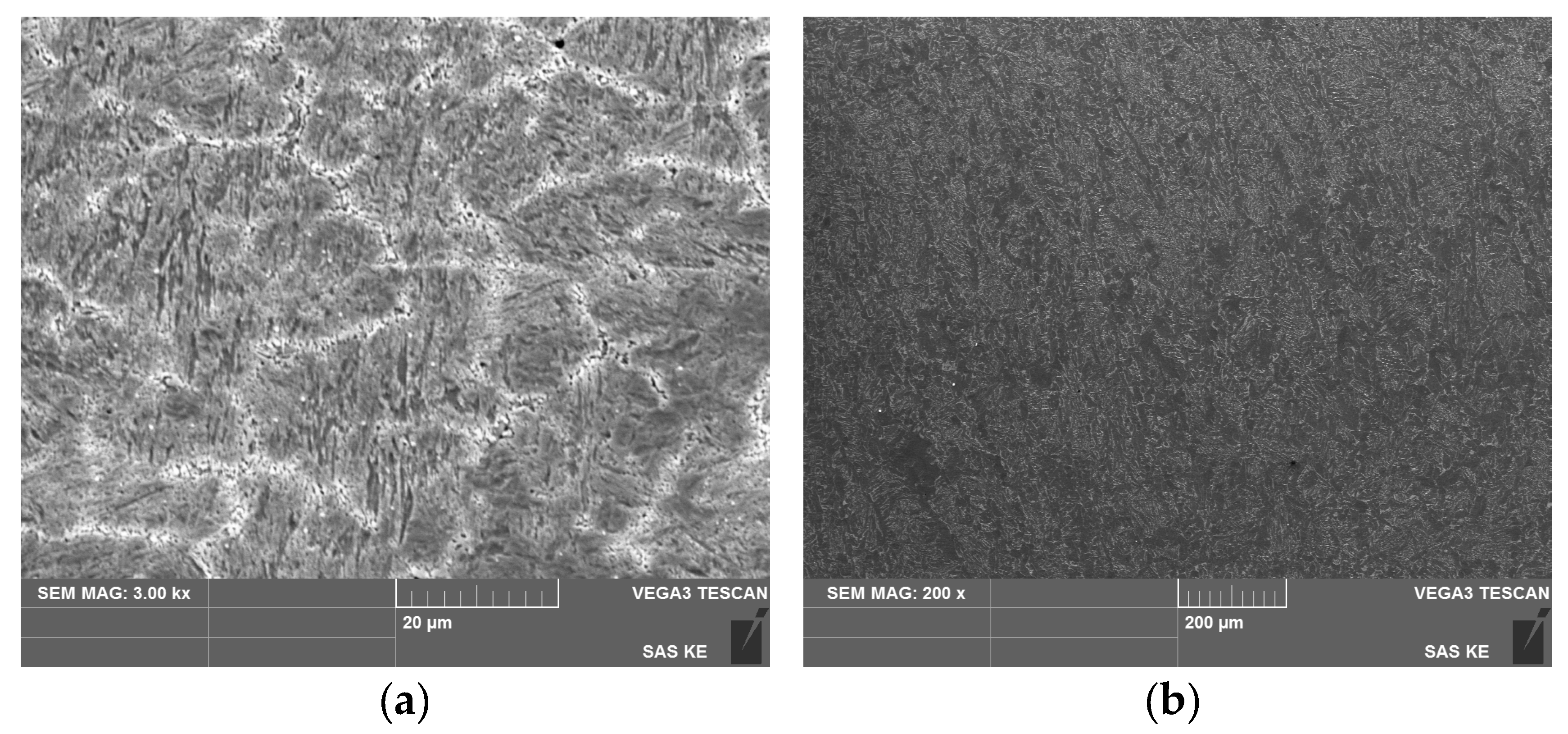
In the metallographic analysis, we evaluated the microstructure of the base material of the working tool and the hardfacing materials. At the same time, we analyzed the interface of the base material of the working tool with the hardfacing material, their mutual mixing and the build-up zone during hardfacing by welding. A metallographic analysis was carried out at the Institute of Materials Research of the Slovak Academy of Sciences in Košice.
In
Figure 9, we see the microstructure of the base material (BM). Cor etchant (120 mL CH
CCOOH, 20 mL HCl, 3 g picric acid, 144 mL CH
3OH) was used to induce the microstructure. The BM has a sorbitic microstructure-a mixture of ferrite and cementite. It is a ferritic-perlitic steel with a higher proportion of pearlite.
In
Figure 10a, we see the hardfacing material of Samples 1. Cor etchant was used to develop the microstructure. We also see the mixing of the base material with the facing material (
Figure 10b). The hardfacing material is mixed without voids, cracks and other defects that adversely affect the quality of the hard deposit cohesion. The hardfacing material has a dendritic microstructure. We can see that the microstructure of the BM has changed in the heat-affected zone (HAZ). We observe the presence of tempered martensite.
In
Figure 11a, we see the microstructure of the hardfacing material of Sample 2. The sample was etched with a Cor etcher. The hardfacing material has a ledeburitic microstructure. It is identical to the microstructure stated by the manufacturer. In
Figure 11b, we can see the interface hardfacing material-BM. The connection of the BM and the hardfacing material is without defects and without breaking the integrity of the hardfacing material and the BM.
In
Figure 12a, we see the microstructure of the hardfacing material of Sample 3. The sample was etched with 2% Nital (solution of HNO
3 in ethyl alcohol). We observe the acicular needle-like structure of BM in the HAZ. In the HAZ, the presence of diffusion between the BM and the hardfacing material can be seen. We can conclude that there was a good mixing of the hardfacing material with BM (
Figure 12b).
In
Figure 13a, we see the microstructure of the hardfacing material of Sample 4. The sample was etched with a Cor etcher. We observe the polyhedral and acicular microstructure of BM in the HAZ (
Figure 13b). We can see that the mixing of the hardfacing material with the BM of the tool is free of cracks, voids and other defects. There was a diffusion of chemical elements between the BM and the hardfacing material.
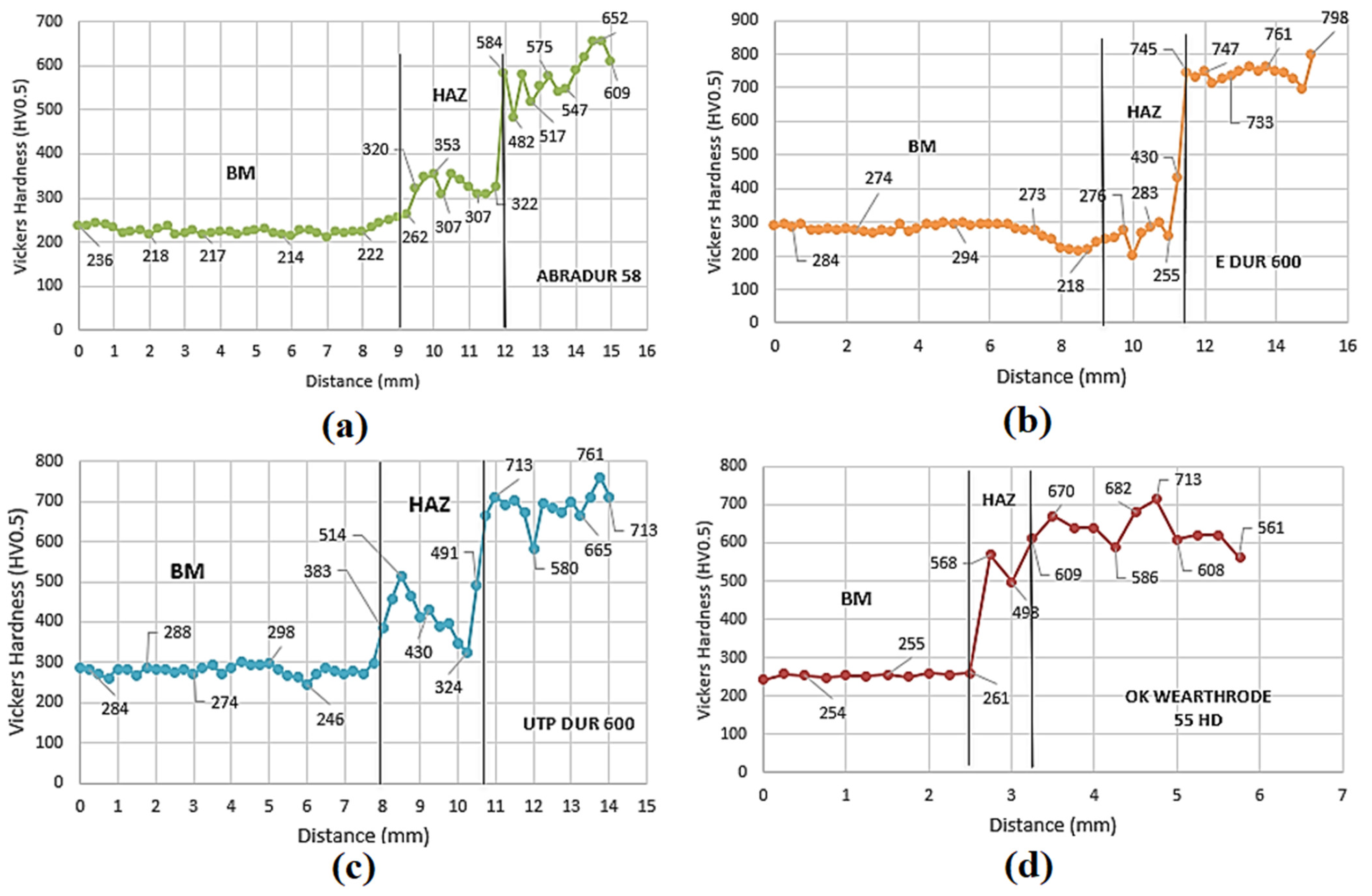
The Vickers-HV0.5 measurement method and the Rockwell measurement method were used to measure the hardness of the base material samples and hardfacing material.
The indentations during measurement were guided from the core of the base material to the surface of the hardfacing material. The average hardness of BM, according to Vickers, was 285 HV0.5. The course of the measured hardnesses on Sample 1 is shown in
Figure 14a. We can see that the thickness of the hardfacing material layer was about 3 mm. The hardness of the hardfacing material is significantly higher than the hardness of the base material of the working tool. The highest hardness value of the hardener was 652 HV0.5. The highest hardness value in the HAZ was 353 HV0.5.
The course of the measured hardnesses of Sample 2 can be seen in
Figure 14b. We can see that the hardfacing material also has significantly higher hardness values than the base material of the tool. The hardness of Sample 2 is higher than the hardness of Sample 1. The hardfacing material layer of Sample 2 is about 4 mm thick. The highest hardness value in the HAZ was 430 HV0.5.
The course of the measured hardnesses in Sample 3 can be seen in
Figure 14c. The highest hardness of Sample 3 hardfacing material had a value of 761 HV0.5. The hardfacing material layer is approximately 3 mm thick. We can see that in the HAZ, the hardness values fluctuate considerably, which could have been caused by uneven mixing of the hardfacing material with the tool base material at the point of measurement or by the structure of the material in the HAZ. The highest hardness value in the HAZ was 491 HV0.5.
The greatest hardness of the hardfacing material on Sample 4 has a value of 713 HV0.5, and in the HAZ, it has a value of 568 HV0.5. The hardfacing material layer has a thickness of approximately 2.5 mm. The course of the measured hardnesses on Sample 4 can be seen in
Figure 14d.
The average measured values of samples and BM microhardness are shown in
Table 4. We can see that the measured hardness values of hardfacing materials are significantly higher than the hardness of BM.
The average Rockwell hardness values of BM and hardfacing materials are shown in
Table 5. We can conclude that all hardnesses of hardfacing materials are significantly higher than the hardness of the base material.
Resistance to abrasive wear was tested according to GOST 23.208-79. For each tested material, three samples were tested. Before the test, the sample is weighed, placed in the device and the feed of the abrasive is started. After each completed cycle, the sample is removed and reweighed to determine the weight loss. The arithmetic average Wh is calculated from the detected weight losses.
First, the
KT hardness coefficient is calculated according to relation (1). This value will provide us with the first information about a possible better or worse abrasion resistance. Subsequently, relative resistance to abrasive wear
Ψh is calculated according to relation (2). BM has a value of 1 because it is a standard sample. All obtained and calculated data from the test of resistance to abrasive wear are presented in
Table 6.
In
Figure 15a, we can see a graphic representation of the
KT hardness coefficients for individual materials. If this value is higher than 1, it is assumed that the tested material will be able to better resist abrasive particles. We can state that the highest value of the hardness coefficient was achieved by Sample 2. At the same time, the lowest value of the
KT hardness coefficient was achieved by BM, namely, 0.39. In
Figure 15b, we can see a graphical comparison of values of relative resistance to abrasive wear
Ψh. It is clear from the graph that Sample 1 achieved the best relative resistance to abrasive wear. It is almost 9.5 times more compared to the BM of the tool. Sample 4 achieved the smallest value of relative resistance to abrasive wear, namely, 2.8. However, it is 2.8 times more compared to the BM of the tool. We can conclude that all the tested hardfacing materials achieved several times better resistance to abrasive wear compared to the BM of the tool.
Some authors report that hardness is strongly correlated with resistance to abrasive wear [
30,
31,
32]. However, based on the results of the hardness measurement and the test of resistance to abrasive wear, we can conclude that the hardfacing material with the highest hardness value (59HRC) achieved a lower value of relative abrasion resistance compared to the hardfacing material with lower hardness (56HRC). The hardfacing material with lower hardness achieved a 2.36 times higher value of relative resistance to abrasive wear. In the results of their research, the authors [
18] also state that hardness is correlated with resistance to abrasive wear. However, from the partial results, it can be concluded that the W-rich alloy reached a lower value of resistance to abrasive wear compared to the Cr-rich hardfacing material, even though its hardness was higher than that of the Cr-rich hardfacing material.


