Article

Application of Quality 4.0 (Q4.0) and Industrial Internet of Things (IIoT) in Agricultural Manufacturing Industry

1
Department of Mechanical Engineering, Punjabi University, Patiala 147002, India
2
Department of Mechanical and Production Engineering, Guru Nanak Dev Engineering College, Ludhiana 141006, India
3
Department of Mathematics and Industrial Engineering, Polytechnique Montreal, University of Montreal, Montreal, QC H3T 1J4, Canada
*
Author to whom correspondence should be addressed.
AgriEngineering 2023, 5(1), 537-565; https://doi.org/10.3390/agriengineering5010035
Submission received: 20 February 2023 / Revised: 25 February 2023 / Accepted: 3 March 2023 / Published: 7 March 2023

Abstract

:
The objective of this research is to apply Quality 4.0 (Q4.0) concept in Agriculture 4.0 (A4.0) to digitize the traditional quality management (QM) system and demonstrate the effectiveness of zero-defect manufacturing (ZDM) in the agricultural part manufacturing industry. An autonomous quality management system was developed based on the ZDM system using the Industrial Internet of Things (IIoT). Both traditional and autonomous quality management systems were evaluated using six-sigma quality indicators and machining and inspection cost analysis. The ZDM resulted in a significant improvement in the quality of CARD148 manufacturing, increasing the manufacturing process from a low level of sigma to a high level of sigma (0.75 to 5.10 sigma). The component rejection rate was reduced by a high percentage, leading to significant economic benefits and a significant reduction in machining cost. The process yield was also increased to a high percentage. The developed ZDM was found to be consistent in improving the quality of the turning process, with notable increases in tool life and reduction in inspection cost. The total component cost was reduced significantly, while the PPM value increased notably. While this study focuses on agriculture-related manufacturing organizations, the developed ZDM has potential for other machining industries to improve sigma levels, particularly in industries such as automotive and medical.

1. Introduction

Before 2020, due to the development of technology and engineering in the agriculture area, an increase in the dependability factor was recognised [1]. The revolution in the agriculture sector during Industry 5.0 (I5.0) has digitalized manufacturing industries, such as agriculture parts manufacturing organisations, automotive component manufacturing organisations, and other industrial units, to improve machining quality, product innovation, and machining efficiency. Therefore, the essential goal is to gain the production dependability of mechanical systems, which are utilised in agricultural machinery. The reliability of agricultural machinery depends mainly on the quality of the equipment manufacturing. The manufacturing sector of agriculture equipment faces a lot of challenges due to technological changes in design during Agriculture 4.0 (A4.0). Quality control (QC) in the manufacturing of agricultural components is solved using some advanced techniques, such as Quality 4.0 (Q4.0), processes capability analysis, total quality management (TQM), etc. [2]. Machinery failure and work failure are directly related to economic factors during cyclic farm shutdown periods, but its life cycle is increasing [3]. It is critical in agriculture part manufacturing to keep spare components in a unified system for proper fitting because agricultural spare parts were previously replaced in the field. If any of the components does not meet the required dimensions, the entire project is halted [4]. The lack of reliability of such compounds, especially the fastener family, is mainly due to the quality of the machining and materials of the machined component. Interchangeability, from a technical point of view, is well-advised as a structural element developed with a certain accuracy of the mechanical parameters. The available gap in machinery leads to mismatching of assembly components, breakdowns during field work, and testing failures. Furthermore, the manufacturing industry’s main challenge is poor machining quality, which leads to increased field downtime. This increased downtime results in financial loss as a result of high repair and maintenance costs. An increased global population increases crop demand, resulting in mass production. Agriculture demands more energy and power to feed the growing world population. The working load on the tractor and other agricultural equipment is higher compared to the previous decade. Now machines continue to work to achieve the target. Breakdowns and an increase in downtime increase the repair cost. This affects agriculture’s profitability. However, management decisions related to agricultural machinery parts repair and replacement can affect profits in many ways. Currently, the agricultural component manufacturing industry is undergoing change due to the technological revolution of I5.0 and A4.0. Developing agricultural equipment is more difficult than it was previously. Because QC and quality management (QM) are needed by the manufacturing industry and end users, different methods and techniques have been implemented in the industry for QC and QM [5]. Most technical attributes are highlighted in this approach. QC in agriculture component manufacturing organisations is a structured approach that could be designed with the end user in mind [6]. Although the machine tool information processing is very slow in traditional QMS, they must overcome machine tool rejection. It is very difficult to process online measurements and inspection of machined components. QC and quality inspection (QI) are some serious aspects of the agriculture component manufacturing units that can be efficiently maintained during the implementation of I5.0. Q4.0 adjusts the concept of QM with I5.0 and I4.0 in order to amend the general demonstration of the manufacturing organisation, the efficiency of machine tools, the quality of the machining, and the innovation of the product [7].
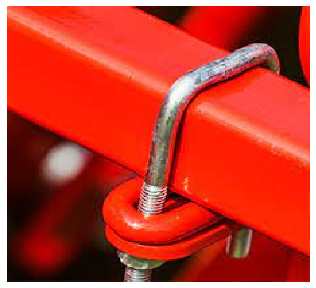
Implementing Q4.0 with I5.0 and I4.0 techniques in an agriculture part manufacturing organisation improves the machined part quality and end-user satisfaction. The U-bolt component is widely used in agricultural machinery including tractors, plows, and tillage, and combines a moving part with some rigid components. In such cases, the shape and size of the U-bolt differ depending on the application, and the replacement frequency of the U-bolt component is higher than that of any other component because this component remains continuous in vibration and loading conditions, but its dependability fails to meet the current requirement. As a result, a study was conducted to identify farmer issues encountered while repairing and replacing agricultural equipment in the field. A zero-defect manufacturing (ZDM) system is designed and developed for the agriculture component manufacturing organisation. This system could control the machining quality of an entire manufacturing cell with individual monitoring of each parameter. Hence, a case study was planned to compile the farmer’s machinery component’s quality requirements by using some traditional QC statistical tools.

1.1. Research Concept and Background

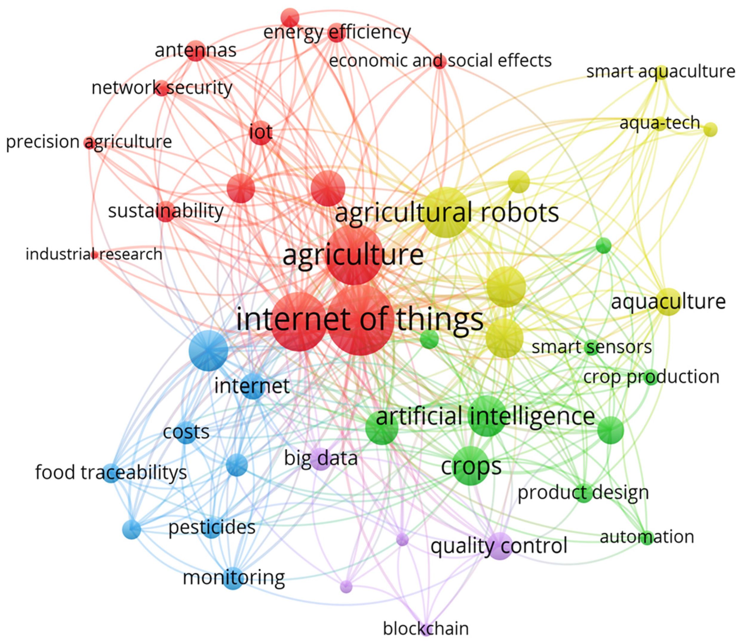
In this study, a literature survey was conducted using the Scopus database to study research background related to the use of the Q4.0 concept in agriculture. This survey utilized specific keywords such as quality 4.0 (or Q4.0); industry 4.0; machining; agriculture; internet of things (or IoT); and industry internet of things (or IIoT), mainly as shown in Figure 1. A total of 31 research papers were identified and evaluated based on their relevance and quality. The analysis revealed that most of the papers were focused on product design, IoT, and agriculture robots, while there were only a limited number of papers on agriculture component machining. This literature survey highlights the need for further research in the area of agriculture component machining within the context of Q4.0.

1.2. Need for the Study

This study is important to be conducted for several reasons. Firstly, it applies the concept of Q4.0 in the agricultural part manufacturing industry, which is an emerging trend in agriculture that utilizes cutting-edge technologies, such as the IIoT, to improve the efficiency and quality of agricultural processes. Secondly, it addresses the need for digitizing the traditional quality management system in the agriculture sector, which is often labor-intensive and time-consuming. The study also has significant economic implications, as it shows that the ZDM system can lead to a significant reduction in component rejection rates, which in turn results in significant cost savings. Additionally, the study demonstrates that the ZDM system can increase the process yield and tool life while reducing inspection costs, thereby improving the overall efficiency of the manufacturing process.
In the agricultural part manufacturing industry, the quality of machining operations depends on the operator’s skill and experience. Mechanical Vernier calipers and micrometer readings are commonly used for inspection techniques and procedures to prevent defective machining. However, to improve machining quality, an autonomous ZDM is often employed. This study proposes the design of an advanced supervision and control system that modifies machining quality during the process. LVDT gauges were installed on the machine to capture real-time data, which was processed using processors and amplifiers to generate inputs for the ZDM module. The ZDM module includes a dimensional values forecaster that is supported by the captured signal, allowing the monitoring of machining quality in real-time by examining the expected and required machined parameters as per customer drawings. The evaluation of the U-bolt manufacturing section will trigger the commands of the machine to correct the tool wear rate, using ladder logic-based progressive integral loops for tool wear rate adjustment. The objective of the ZDM module in this study is to control the machining parameters of the U-bolt in a precise manner until the OEM customers’ technical requirements and ISO standards are met. The use of a ZDM system to monitor, predict, and control a machined component’s parameter is critical, as this practice recognizes quality based on its ability to influence the cognitive state [8]. Moreover, due to its unmatched performance in conventional and numerical control (NC) systems, the ZDM module is becoming increasingly popular. The ZDM module has been demonstrated to be superior to other SPM, conventional, and CNC controllers. Previous case studies have shown that the use of LVDT can effectively solve issues related to machined product quality. In this study, the ZDM method has been chosen to design the machined product quality. A case study will be conducted in the U-bolt manufacturing section of an agriculture component manufacturing organization to validate the effectiveness of the ZDM system.
Figure 1. Illustration of literature analysis by highlighting the significant keywords [9,10,11,12,13,14,15,16,17,18,19,20,21,22,23,24,25,26,27,28,29,30,31,32,33,34,35,36,37,38,39].
Agriengineering 05 00035 g001

2. Research Methodology

The case study was conducted at GS Engitech Pvt. Ltd., which has been certified to ISO 9002:2008 for quality systems and has implemented TQM and stringent quality assurance techniques. A comprehensive assortment of high-precision machined components is required for use in a variety of industries where excellent performance, quality, and delivery are required. Figure 2 shows the research methodology representation in the case organization. The items are finely engineered and are perfect for use in a variety of industries. Case organization is a leading manufacturer of high-quality, precision-machined, and sheet-metal components for agricultural machines, such as mounting parts, rotors, and I- and U-bolts, among other components. High-quality machining centres and CNC turning, threading, and grinding machines are used in the case organisation. The quality of the machined component is an important factor. Normally, machined components are used in assembly parts. The machined parts’ dimensional accuracy is required up to the mark for fitment purposes. Advancements in machine tools improve manufacturing performance, but traditional QI and QC tools are ineffective in this context. The I4.0 and I5.0 revolutions in the manufacturing sector require some advanced machine tool quality assurance techniques. ZDM is one of them, in which some close-loop advance quality control features are implemented in a manufacturing section. ZDM automatically controls and monitors the machined parts’ quality with record-keeping. This is an advanced system that controls the machined part’s quality online and shares quality reports through CLOUD with production managers and the quality department. These data are further shared with customers. In mass production, individual reports and data for a single product are difficult to maintain. ZDM helps shop floor management with some auto-reporting tools.

2.1. Selection of Manufacturing Section

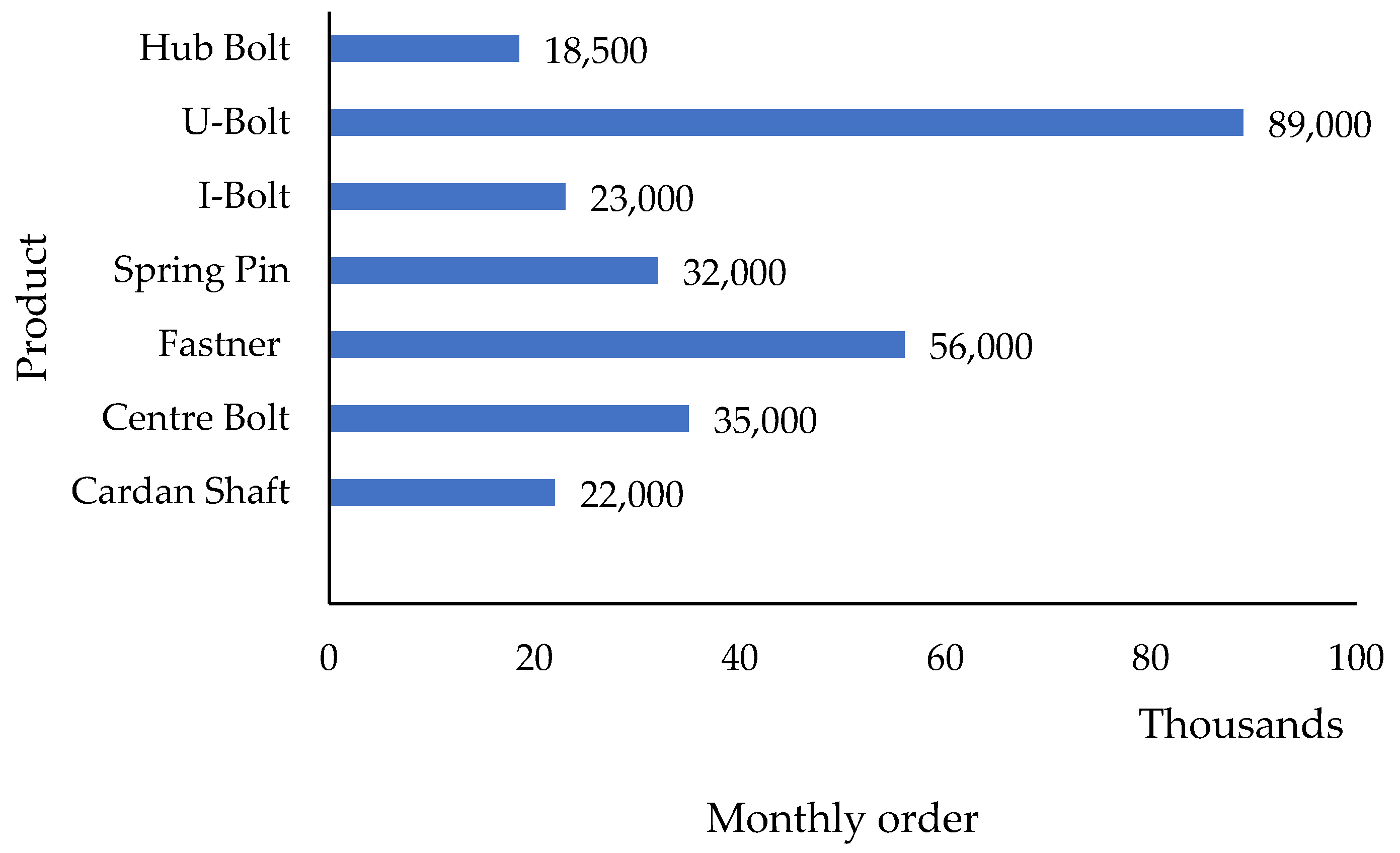
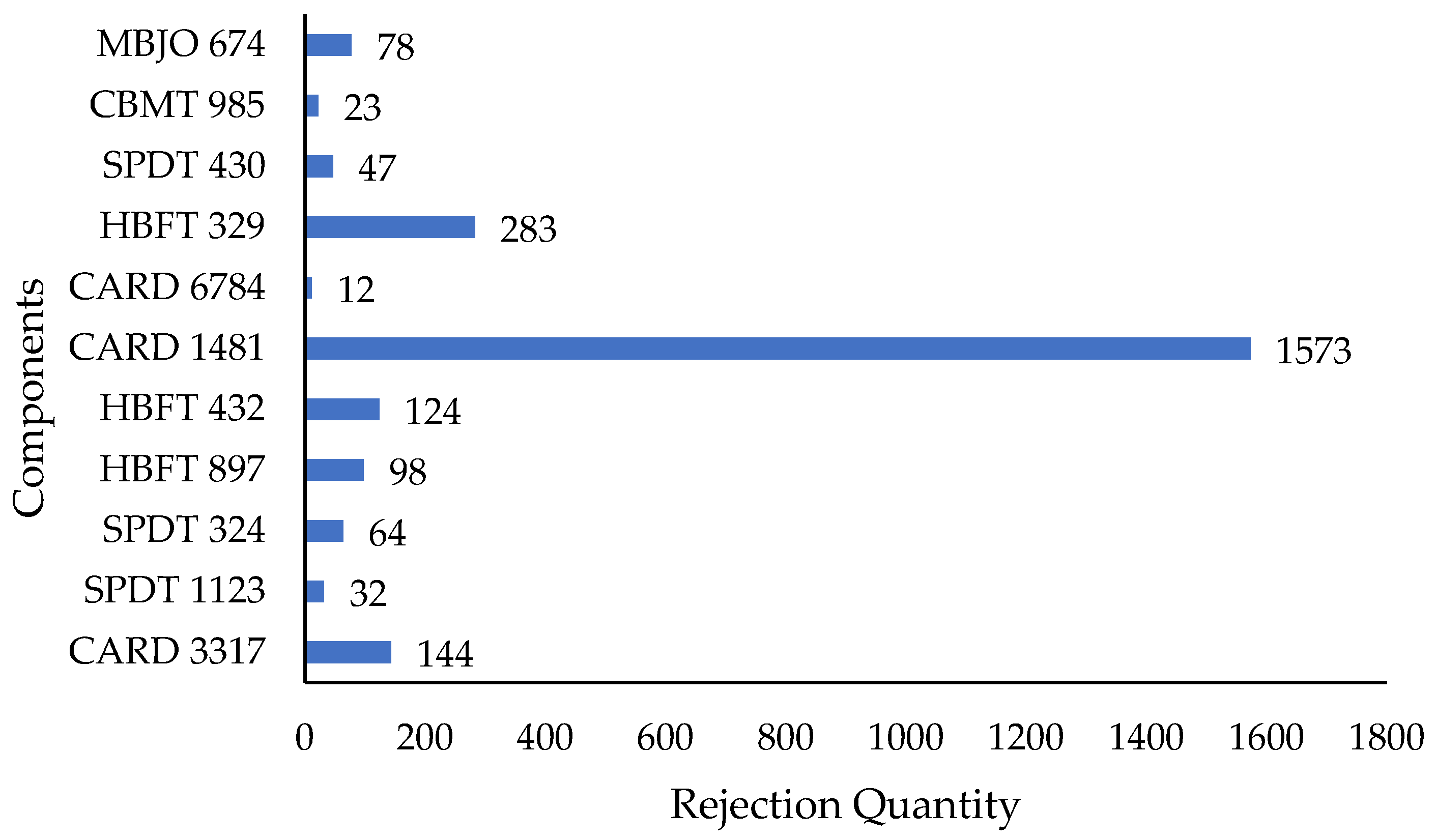
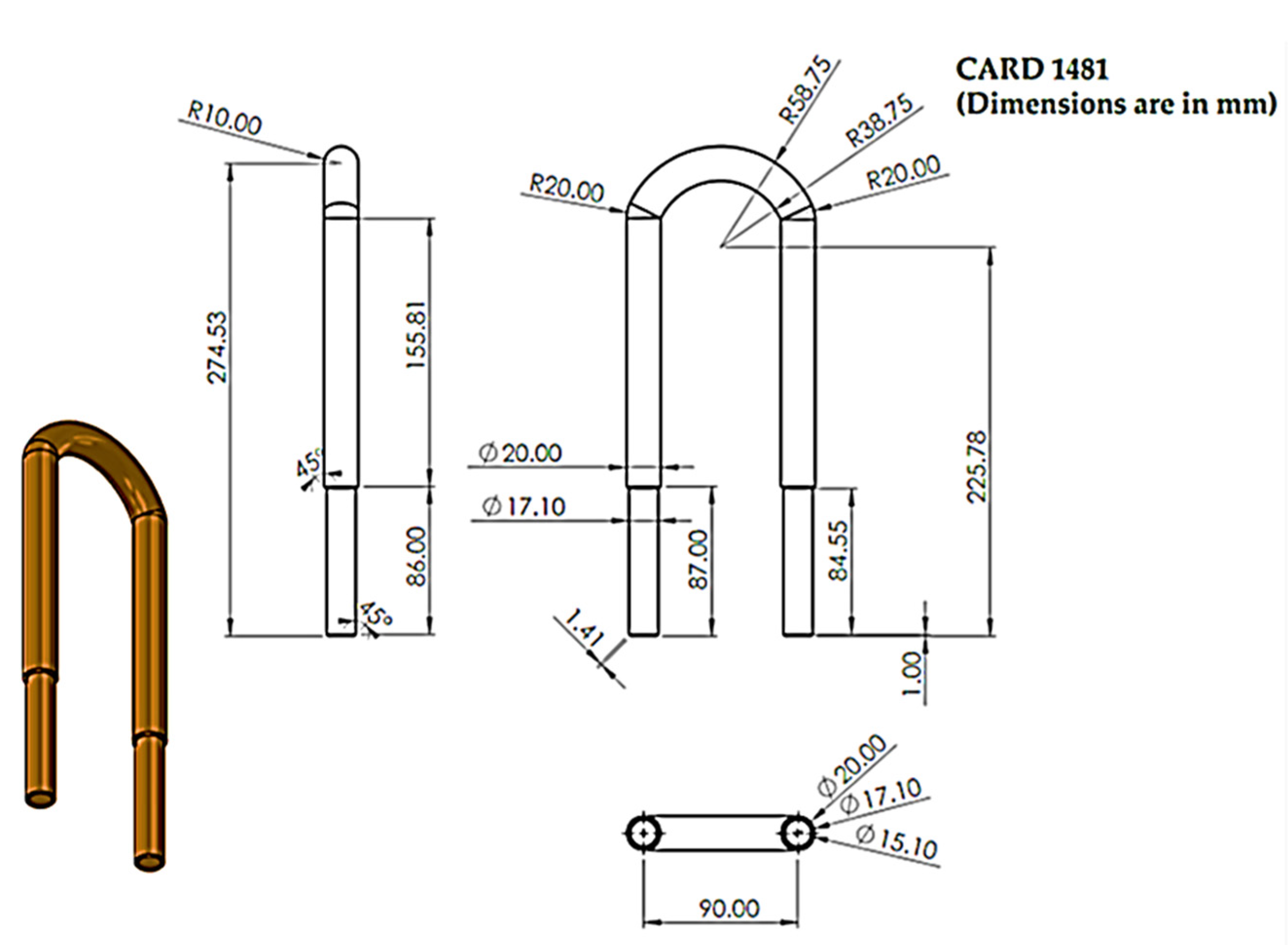
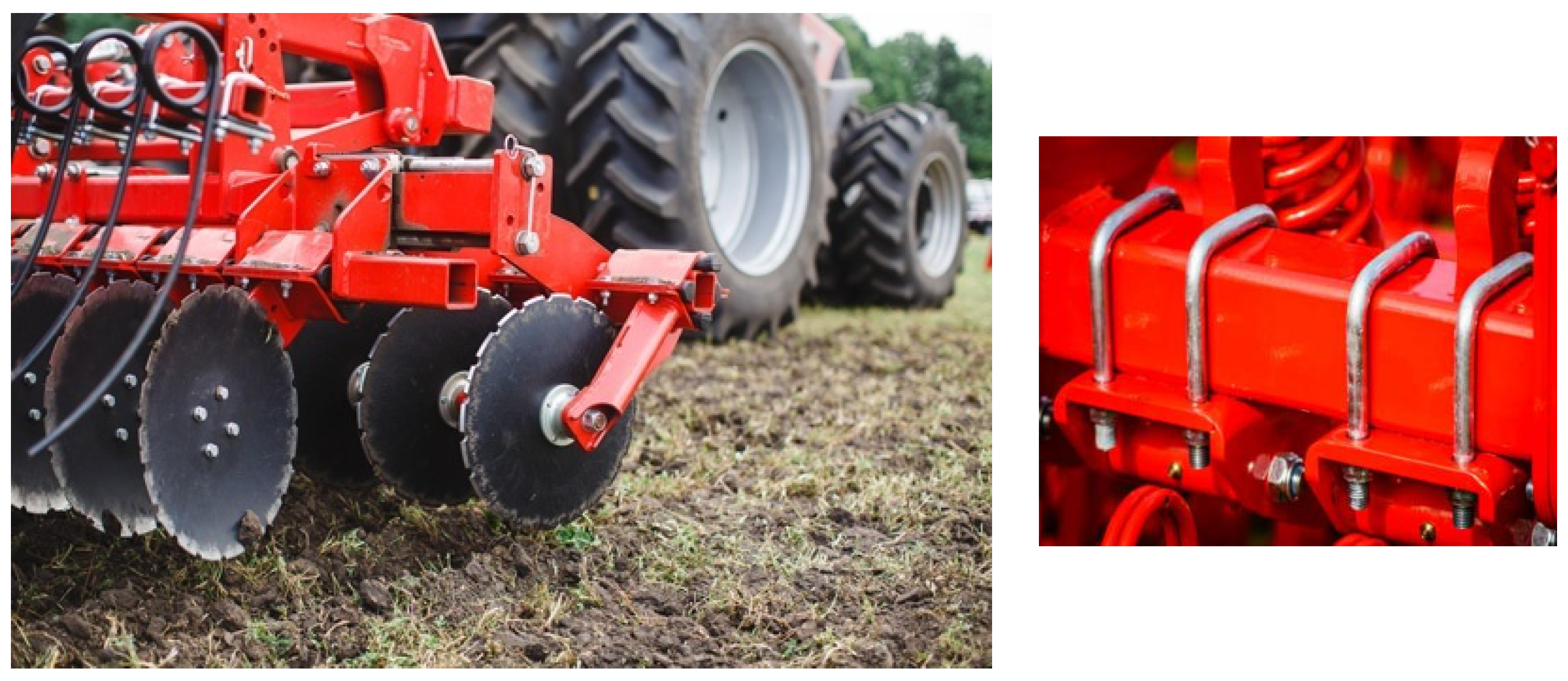
In the case organisations advance, CNC, NC, and VMC machines are used to perform manufacturing processes. After analyses in the industrial U-bolt manufacturing section data, Figure 3 shows the monthly order quantity of the case organisation; the CARD1481 product, which is machined in the U-bolt manufacturing section, was selected for this case study based on this. Case organisation schedules entire categories of products in the CNC machine shop. Based on the machining parameters, the machining process determines criticality. Some critical dimensional tolerances are difficult to maintain because of their high rejection rate. CARD 1481 was chosen for this case study based on its rejection rate, as shown in Figure 4. The CARD1481 rejection quantity is 1573 pieces; this was 63.4 percent of the total rejection of the shaft manufacturing section. On the basis of the high rejection rate and high volume of orders, the CARD 1481 product was selected for the case study. The CARD 1481 bolt is manufactured in the fastener manufacturing section, where a combination of CNC and SPM machine tools is used. Figure 5 represents the detailed drawing of CARD1481. The CARD 1481 bolt is used in the suspension of heavy commercial vehicles (HCV) and medium commercial vehicles (MCV), as shown in the assembly view in Figure 6. This bolt holds the entire axle unit and suspension to the chassis ladder frame during work. A detailed analysis of the selected product will be reviewed in the following sections.

2.2. CARD 1481 Manufacturing Process Analysis

In the U-bolt manufacturing section of organization CARD 1481, a combination of CNC and special purpose machines (SPM) are used for machining. This section is advanced and includes an advanced CNC turning centre selected based on the operation of the machining and the dimensional tolerance for fitment purposes. The quality of machining affects the quality of the machined component, making machining accuracy an important factor. To achieve the desired result, the CNC turning machine was evaluated using process capability analysis.
High dimensional accuracy is difficult to achieve in production where operator skill is lacking, and machine tool usage continues to impact machining quality. It is very important to monitor the machine tool and make fine adjustments. The skill of the operator is required for tool wear correction and other parameter correction. Human error can sometimes result in a high rejection rate. This requires an autonomous system for turning machines for fine adjustments in tool wear compensation and other parameters.
The ZDM system is required to design and develop a CNC turning machine. The development of ZDM for CNC turning machines founded on the I4.0 concept resulted in amendments and necessary improvements to the CNC turning setup. In the ZDM system, the machine tool measures the machined component during the machining process and sends a digital signal to the processing unit after the machining process. In a CNC turning machine, the CNC controller is the main unit that receives and processes the signal. After processing the signal, this ZDM unit puts a digital value on the machine wear parameters.

2.3. Process Flow Analysis with Rejection Quantity Response Data

Both ends of the CARD 1481 bolt have two threaded portions. A CNC turning machine tool is used for turning, chamfering, and threading operations. Table 1 shows the process flow diagram of the CARD 1481 bolt in the a or b part. This includes machining process 90 (end facing chamfering) on a CNC turning machine 500HD; machining process 100 (step turning diameter turning and chamfering) on a CNC (CTC 500); machining process 110 (pre-roll diameter grinding) on a CNC grinding machine; and operation number 130 (threading) on a CNC Super Cut 300. Further detail regarding the machine process, including a process flow diagram and information on variation, is shown in Table 1. The characteristics of the product and the process are also shown in Table 1. The incoming source of variation explains the type of defects faced during the manufacturing operation with respect to product characteristics, where the dimensions of the machined components are explained, and the process characteristics on the CNC machine tool section, such as the machine condition, and the tool condition in the manufacturing process, such as the 110 grinding wheel condition, are explained in detail.
Appendix B shows the step-by-step control plan for the CARD 1481 bolt, which includes a detailed discussion of the machined components, as well as customer and vehicle information. In the left corner, there is a part family group, part family name, and supplier detail. Appendix B includes the part process name, operation description, machine, jigs, and tools. The machining process with an assigned process number is shown in the first and second rows, and the dimensional characteristics are shown with tolerance in other rows and columns. The machining operations with a detailed description of quality measuring apparatus are also provided. The sample size and sampling frequency are set based on the dimension and operational frequency of the machining process. Central quality issues the control method with some standard quality procedures. These procedures are used across the entire part family. Also, some original equipment manufacturers (OEMs) require these standard procedures to ensure the quality of their products.

2.4. System Design

Manufacturing advancements are being made as the industrial manufacturing era progresses through the I4.0 and Industry 5.0 (I5.0) revolutions. This technological advancement results in agriculture-part manufacturing units, and several types of SPM, HMC, CNC, and VMC machine tools are used with advanced machine control. This machine tool operating system is closed-loop in nature, in which, after machining, the machine tool does not inspect the machined part. After machining, inspection and amendments to the machine tool take a lot of time and increase the rejection rate on the shop floor. Individual machining of defective parts affects the performance of the entire manufacturing cell. With this system, the overall PPM rate is increasing. Another disadvantage of this approach is that it necessitates additional manpower for quality inspection and monitoring for report generation, as well as quality inspection and control. The development of a ZDM system that will maintain the machining quality during CARD 1481 machining is necessary. An LVDT gauge setup was developed and installed on the machine to capture RT data for fine amendment in tool wear. This ZDM module includes a dimensional values predictor for a machined product that is supported by the captured readings of a machined workpiece to be monitored in RT by examining the required machined parameters as per customer drawings. Furthermore, due to conventional and numerical control (NC) systems, the ZDM module gradually becomes more functional. ZDM has been proven to be better than other SPM, conventional, and CNC controllers. However, in this case study, ZDM is the selected method for designing the machined product QM. A case study in CARD 1481 manufacturing under the agriculture part manufacturing organisation will validate the ZDM system. The controller design and methodology in this research have the following elements:

2.4.1. Design

Machined component examinations are recorded using the ZDM setup. Process capability assessment is performed before and after ZDM implementation to carry out experimental trials on the CARD 1481 machined component. Data are collected to analyse the machining process capability and the rate of manufactured product rejection.

2.4.2. Monitoring Module Design

The ZDM measurement system for the CARD 1481 manufacturing consists of a closed-loop LVDT measurement system. The output signals captured by the LVDT gauges are sent to the amplifier for data processing. The ZDM processing unit processes these input values before sending them to the machine control for fine-tuning. The machine controller will use this input value and correct the desired dimension automatically.

2.4.3. Validation

The ZDM module is tested in an RT environment and in an agriculture part (CARD 1481; manufacturing organisation). Validation of the results of the traditional QM and ZDM systems is carried out.

2.5. Development of ZDM

This section explains the ZDM development procedure for this research work. The ZDM control design procedure is explained in the following steps:
  • Machining Quality Measuring Model-Quality Analysis: The machine product quality is measured with the ZDM LVDT setup installed in each individual machine tool. Six-sigma process capability analysis has been performed, including before and after implementation, for experimental trials of CARD1481 manufacturing. The data were collected in Excel files in a quantitative model to analyse the statistics between the machine tool wear rate values.
  • ZDM Device–Autonomous Measuring System: In addition, the presented data would be utilised to design and develop an autonomous measuring system. The measured value of the machined product will be automatically used as input, while the results are generated by the ZDM system. This phase consists of designing and developing an autonomous system to measure, monitor, and control real-time machined data.
  • Supervision Design: The ZDM system will be engaged to develop the correction system that triggers the autonomous measurement system. The result of the CARD1481 manufacturing is compared to the desired machined tolerances as per OEM drawings so that the machining error is evaluated. This input value is sent to the ZDM system, which is further used as an input value to a machine tool. This input value is used as a fine amendment to the ZDM system.
  • ZDM Validation: The ZDM system was developed using the ESP32 module, and testing has been performed in the CARD1481 manufacturing section. Testing ZDM on a manufacturing shop floor will evaluate the effectiveness of the ZDM module and control the quality of the machined component. Moreover, the RT assessment is an important step before implementing the physical system. A comparison between the machined product quality in current practices and the ZDM module results will be carried out. The process then begins by feeding the desired parameters from the customer’s drawing into the ZDM module as an initial condition. Each machine product is measured automatically, and individually captured measurement readings are fed into the ZDM system. Consequently, the measurement values of the machined product will be analysed, demonstrating the capabilities of the machining process and automatically correcting the tool wear rate.

3. Results and Discussion

This section discusses the results of the developed ZDM system (part per million comparisons of CARD1481 manufacturing; rejection rate comparison per month; improvement in quality; production comparison; machining cost and measuring cost comparison). A process capability analysis was performed before and after development of the ZDM system.

3.1. Assessment of Traditional Quality Control System of CARD 1481 Machining

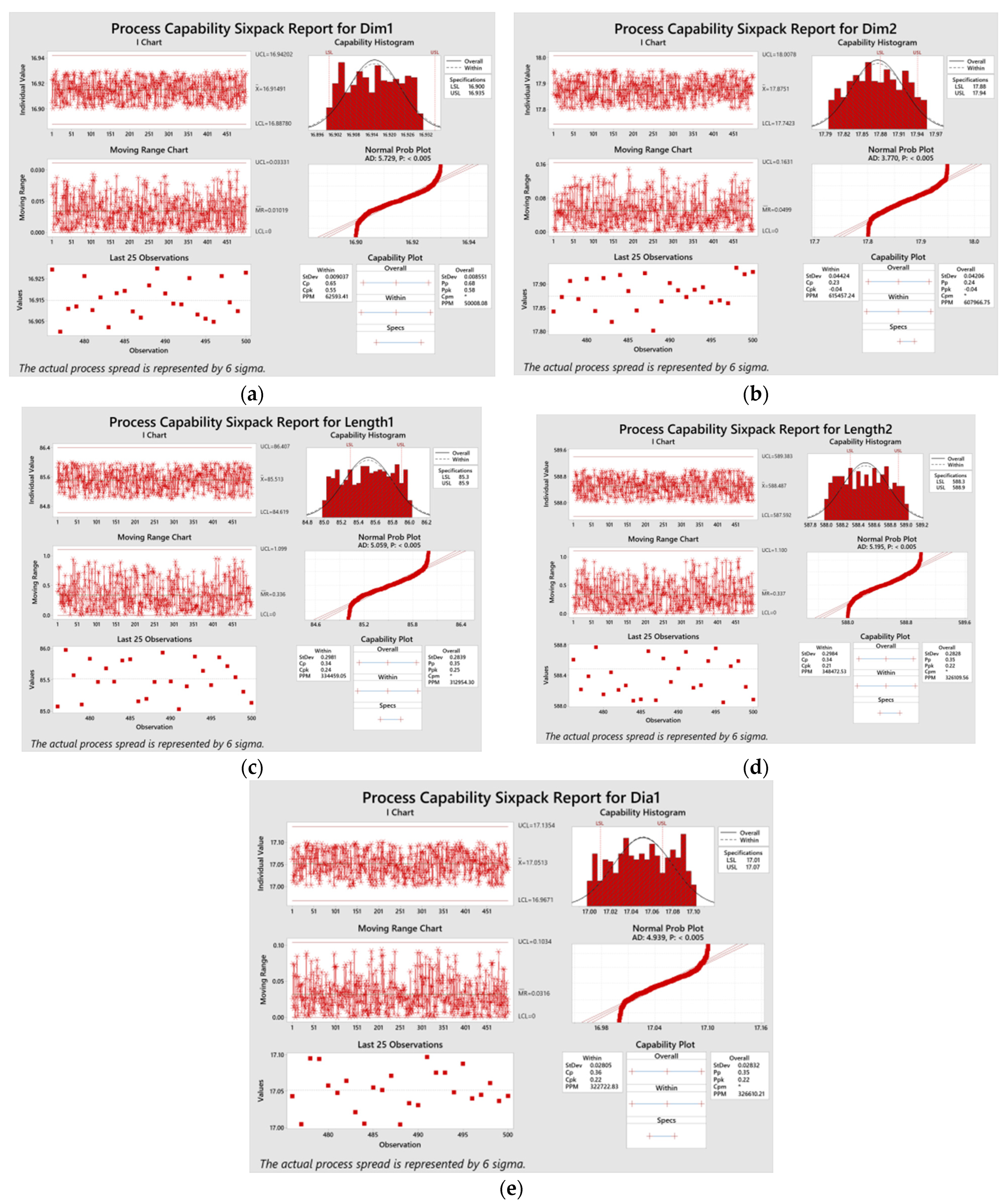
The CARD 1481 manufacturing section uses traditional quality control systems to measure and control the machined quality of the product. These traditional quality approaches are not very effective because online fine tuning on the machines is not possible. That is the primary reason for the increased rejection. Also, the manufacturing organisation observed at the final stage and on the customer end affects the case organization. Defects in the CARD 1481 bolt are observed due to a measurement error by the operator and a fine amendment in the machining process during manufacturing. In the selected manufacturing section, some manual QC and QM apparatuses, such as Vernier calipers, micrometres, and plug and snap gauges, were utilised to quality inspect and control the CARD 1481 bolt. The specially designed snap, ring, and plug gauges are convenient for the CARD 1481 bolt. As a result, the machining quality of manufacturing products is determined by multiple gauges that are required for various machining processes, resulting in high inventory carrying costs and preventive maintenance costs. Moreover, manual Vernier and micrometre measurements cause unevenness due to variable operator skills. Human measurement errors are possible because of high production. The quality managers reported a position of miscommunication between machine operators and quality inspectors, which were responsible for the machine measurement errors. Observed machining faults are normally the result of human error. Process capability six-sigma analyses have been performed with the help of Minitab 21 software for evaluating the machined product quality.

3.1.1. Machining Operation Capability Assessment of CARD 1481 Machining Process

A process capability six-sigma approach was utilised with the help of Minitab 21 to evaluate the process capability of the CARD 1481 machining process. The manufacturing process capability would determine whether the manufacturing process is under control or not, following the normal distribution curve. To evaluate the manufacturing operation process capability and process performance index, Cpk (process capability index), Cp (process capability), Ppk (process performance index), and Pp (process performance) were used. The CARD 1481 machining operations were carried out to maintain three diameters (Dia1), two dimensions (Dim1 and Dim2), and two lengths (L1 and L2). Figure 7 depicts the visualisation of the machining process’s performance and capability. Further, the responses for the measured dimensions—length and diameter—were evaluated and computed to acquire the Ppk values and Cpk values. The mean values of Ppk and Cpk have been calculated to be 0.25 and 0.28, respectively. When the calculated values were compared to the six-sigma chart, it was discovered that the current machining operation was at a 0.75-sigma level. Moreover, the defect per million opportunities (DPMO) in the traditional QM current machining process range is 758036, which cannot be acceptable for the fitment purpose of an agricultural machinery setup.

3.1.2. Analysis of the Rejection Response of CARD 1481 Manufacturing Section

The Card 1481 manufacturing process’s rejection rate is high because of some critical dimensional tolerances. Appendix A shows the potential failure mode and effect analysis of the CARD 1481 bolt. This table displays information such as the operation number, machining operation, cause, prevention, detection, and so on. This table assists us in determining the cause and effects of the rejected work piece. Furthermore, the cause of rejection based on the defect detection approach is also displayed in this table. Table 2 depicts the rate-response analysis based on the process failure mode and effects analysis (FMEA). In this table, operations 90, 100, 110, and 130 have a high rejection rate. This rejection amount accounts for 92.22% of the total rejection. According to Appendix A of the FMEA, operation number 90 represents 24.66% of the total rejection, operation number 100 represents 22.73%, operation 110 represents 22.18%, and operation 130 represents 22.73%. This also shows the high rejection of CARD 1481 bolts comes only from these four operations. The machining process is 92.42 percent of the total rejection of the CARD 1481 bolt.

3.2. Machining Process Capability Assessment with ZDM System for CARD1481 Machining Process

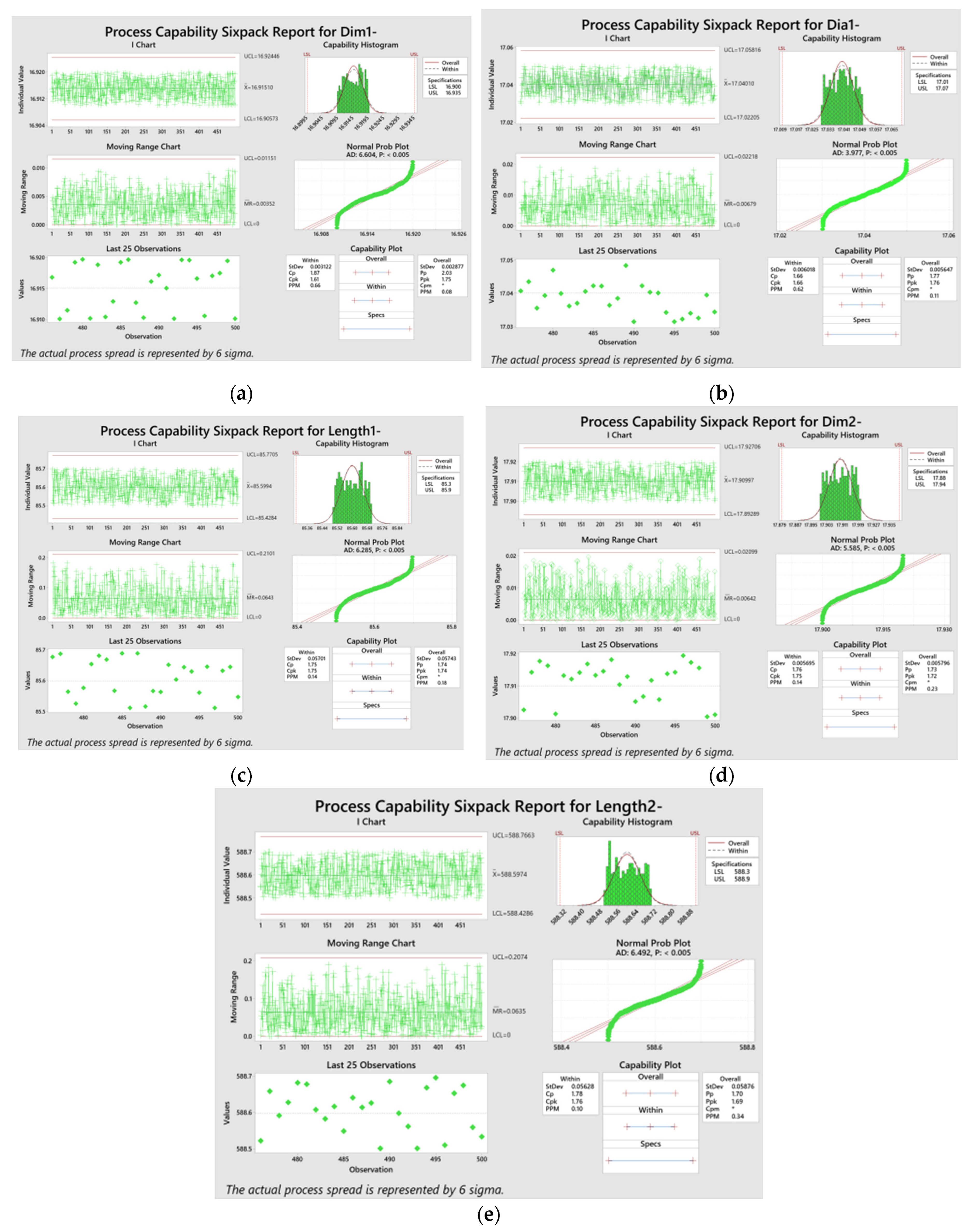
Production has begun following the installation of the ZDM system in the CARD1481 manufacturing section. After capturing with the help of the ZDM module on ESP 32, we process the captured data according to the developed logic. The entire machined batch of CARD 1481 bolts was analysed using Six Sigma process capability analysis with the help of Minitab 21. The capability of the manufacturing process would determine whether the machining operation is under control or not. The CARD 1481 machining operations were carried out to maintain three diameters (Dia1), two dimensions (Dim1 and Dim2), and two lengths (L1 and L2). Figure 8 illustrates the overall process capability visualization. In addition, the main response for the dimensions analysed was evaluated to obtain the Cpk and Ppk values. The Cpk and Ppk values were calculated and found to be 1.706 and 1.732, respectively. The calculated results were compared with the Six Sigma and the manufacturing operation was determined to be operating at the 5.10 sigma level. Moreover, the defect per million opportunities (DPMO) value in the current machining operation range is 233, which will be acceptable for machine fitting purposes.

3.3. Traditional QM and ZDM Comparison

Traditional QM and ZDM were compared using Six Sigma quality measures, such as Pp, Cp, Ppk, and Cpk. The ZDM system autonomously maintains the machining process parameters with the help of the LVDT setup. A closed-loop system was attached on the CARD1481 manufacturing section’s machine tool. Table 3 shows the overall manufacturing capacity and comparison. The parameters D1 and L1 represent the traditional quality management and ZDM systems, respectively. The AIAG standards did not accept the performance and capability of the traditional QM system. Furthermore, the machining process’s QM techniques were found to be within 0.75 sigma. The ZDM has significantly increased machining capability, approaching 5.10 sigma. Furthermore, for the selected parameters, the PPM rate was significantly lower. This shows that the rate of parts being rejected has also dropped significantly, which means that the manufacturing industry has saved a lot of money.

3.4. General PPM Comparison of Traditional QM and ZDM

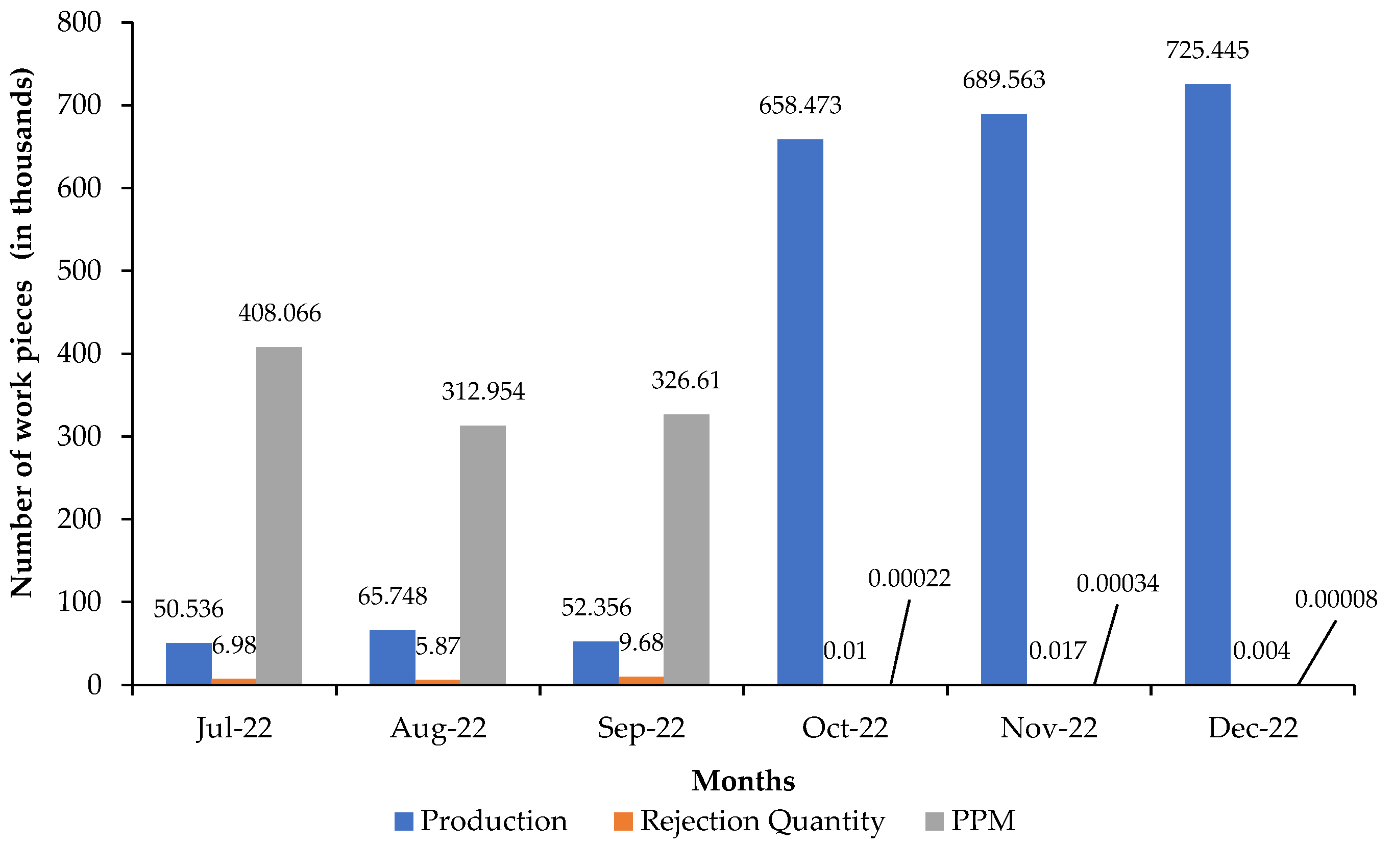
The ZDM stores entire measured values of CARD1481 in the cloud for analysing the PPM rate. The LVDT setup, which is installed on the machining center, is connected to the ZDM system for capturing the machining dimensions. The captured dimensional values were analysed in Minitab21. The general PPM in traditional QM and ZDM is depicted in Figure 9. The results reveal an important reduction in PPM rates after the implementation of the ZDM, indicating cost savings for the manufacturing of CARD1481. The PPM was improved by 98.60% in the ZDM.

3.5. Response to the Comparison of the Rejection Rate

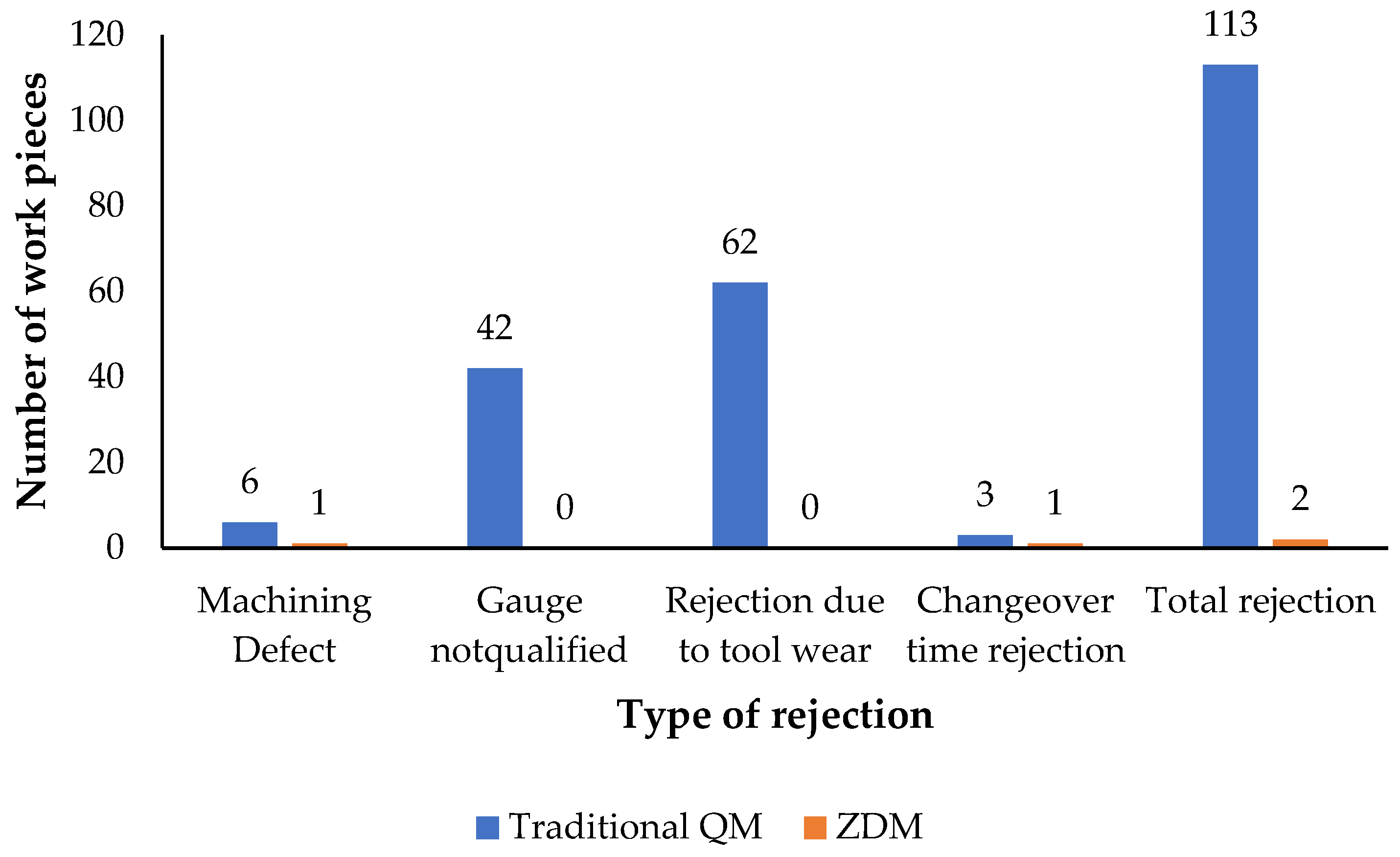
The component rejection response was investigated in traditional quality management. To begin, daily rejection data was analysed to determine the different types of rejection. According to Figure 10, traditional QM causes the highest percentage of rejection due to tool wear from 62 pcs to 0 pcs, which is 54.86 percent of the total rejection; machining defects from 6 pcs to 1 pcs, which is 5.3% of the total rejection; gauge errors from 42 pcs to 0 pcs, which is 37.168 percent of the total rejection; and changeover at 2.65% of total rejection, that is 3 pcs to 1 pc. After implementing the ZDM, the rejection response was observed and analysed. It can be seen that rejection due to gauge defects and insert wear was eliminated; rejection due to machining defects was 83.3 percent; and changeover was reduced by 96.66 percent using ZDM.

3.6. Quality Improvement in Machining

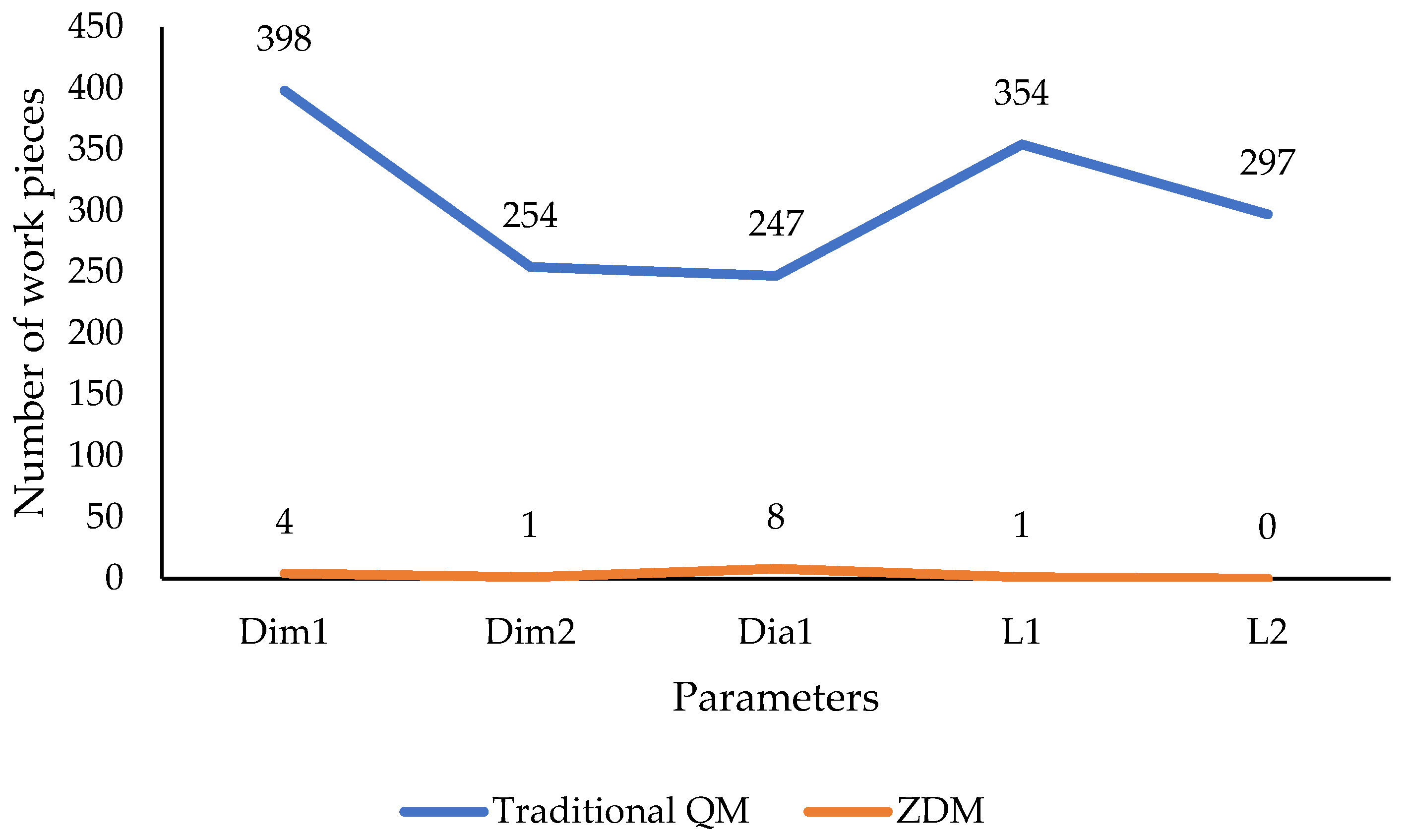
Furthermore, the defect identification on the CARD1481 manufacturing setup was analysed by comparing the traditional QM and ZDM. The entire data comparison response is depicted in Figure 11. The ZDM was used to discover that defects were reduced by 99.4 percent. As a result, the ZDM was able to improve the quality of the components while decreasing the rejection.

3.7. Machining Cost Analysis

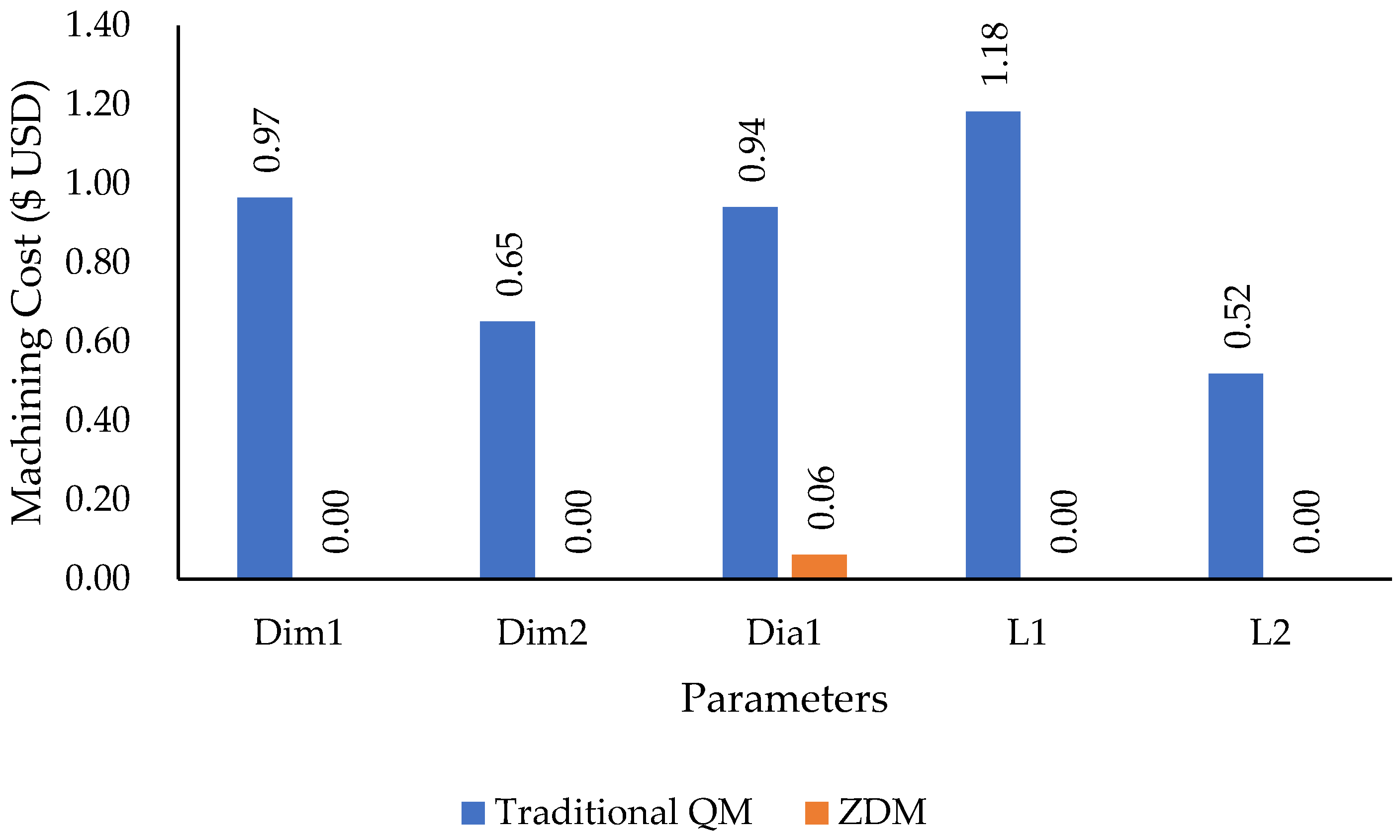
The comparison of CARD1481 manufacturing costs has been analysed and the results of the ZDM system were used to calculate the machining cost per component. The machine hour rate is an industrial standard to calculate the cost of components. In the CARD1481 process, a machine tool with standard MHRs is available. In the current study, the machining hour rate (MHR) was assumed to be constant. According to cost-per-component data, the cost-per-component with the traditional QM system has been reduced with the observed improvement of 86.36%.

3.8. Machining Process Analysis

Since implementing the ZDM, a significant amount of value-added work has been eliminated, as illustrated in Figure 12. The current system’s cost has been reduced by eliminating rework operations. A 98.59 percent improvement was observed after the implementation of the ZDM system.

3.9. Cost of Inspection

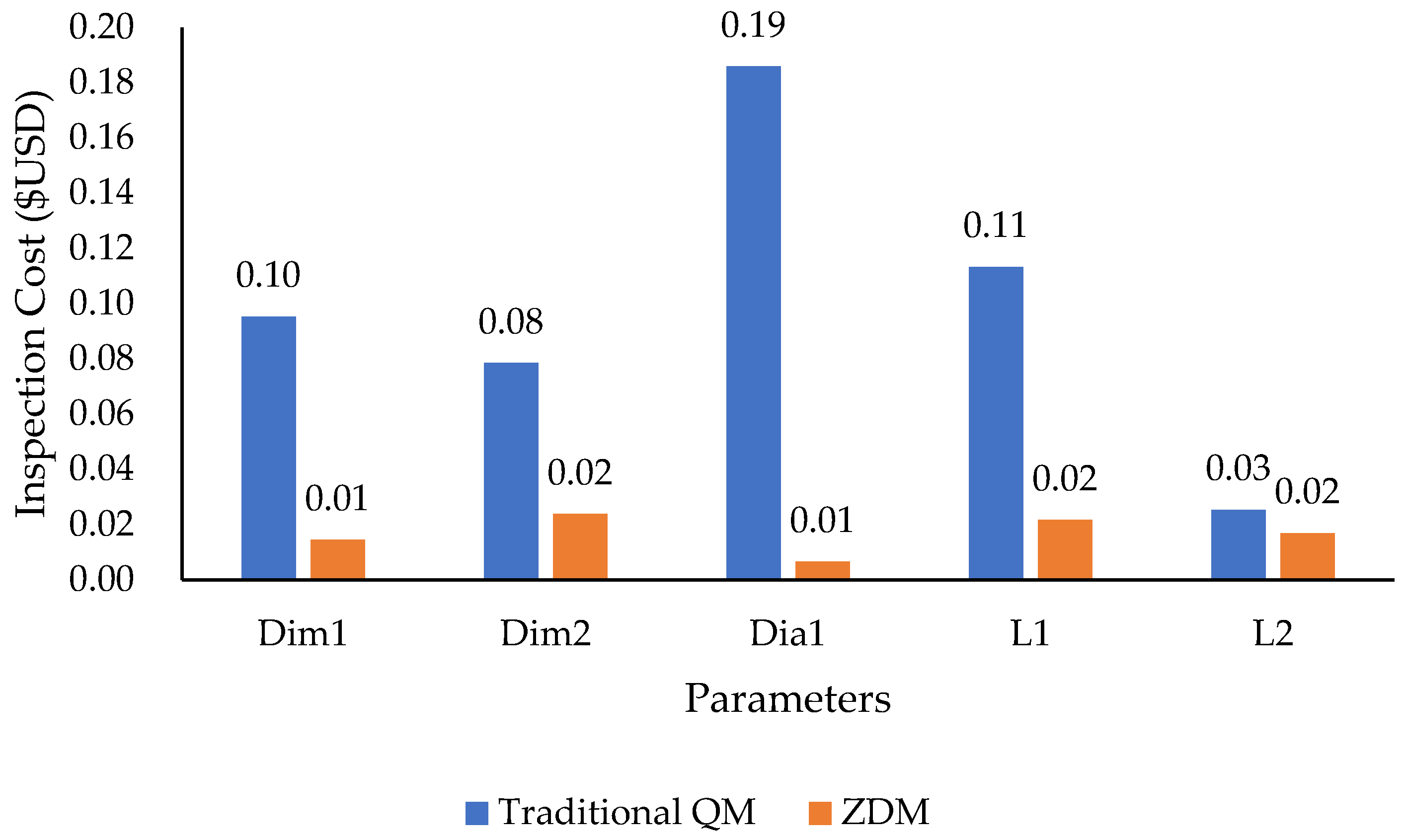
The CNC turning process required the use of several gauges and a quality inspector. The other machining processes are dependent on the prime machining operation, so it is necessary to inspect it thoroughly. Otherwise, re-inspection may be required, which will increase the costs. As stated previously, the machining process in the ZDM improved significantly. As a result, the reworking operation’s inspection costs were also eliminated. Furthermore, as illustrated in Figure 13, the implementation of ZDM has reduced the cost of quality inspection. As a result, the overall cost of the manufacturing process has been reduced by 84%.
The most important factor in tool life has been identified as unskilled labor. In most cases, untrained labor enters incorrect wear parameters into the machine after taking manual observations of the machined component. However, the machine produces inconsistent results, resulting in a shorter tool life. Drilling, tapping, boring, facing, and milling operations were performed with traditional QM tools. On the Dim1, there was a savings of 51 percent; in Dim2, 78 percent; in Dia1, 65 percent; in L1, 40 percent; and on L2, 61 percent, with an overall tool life increase of 59 percent in the CARD1481 manufacturing process, as shown in Figure 14.

4. Conclusions

In conclusion, the implementation of the ZDM in the CARD148 manufacturing process has resulted in significant improvements in product quality. The ZDM developed was effective in increasing the manufacturing process and reducing the rejection rate, leading to significant economic benefits. The process yield was greatly improved, resulting in a higher level of consistency in the quality of the turning process. The ZDM also resulted in an increase in tool life and a reduction in inspection costs. Overall, ZDM has future implications across various industries. It may reduce component rejection rates, increase process yields and tool life, while reducing inspection costs in the automotive industry. This approach may improve the quality of medical devices and reduce manufacturing costs in the medical industry. The food industry may use the approach to enhance food quality, safety, and traceability, while the pharmaceutical industry could improve drug manufacturing quality, reduce costs, and ensure regulatory compliance. The broad range of applications indicates the potential to revolutionize traditional manufacturing processes, enhance quality, and reduce costs. Therefore, the ZDM can be a valuable tool to improve the quality of the manufacturing process.

Author Contributions

Conceptualization, J.S. and I.S.A.; methodology, H.S.; software, J.S.; validation, J.S., H.S. and A.S.; formal analysis, J.S.; investigation, J.S.; resources, A.S.; data curation, J.S.; writing—original draft preparation, J.S.; writing—review and editing, A.S.; visualization, J.S.; supervision, H.S. and I.S.A.; project administration, A.S.; funding acquisition, J.S. All authors have read and agreed to the published version of the manuscript.

Funding

This research received no external funding.

Data Availability Statement

The data is currently unavailable due to privacy and ethical considerations.

Acknowledgments

The authors would like to thank M/S GS Engitech. Ltd., Ludhiana (India), for providing necessary work facilities for this research work. The authors would like to express their gratitude to AysRox Solution Pvt. Ltd. for technical assistance.

Conflicts of Interest

The authors declare no conflict of interest.

Appendix A

Table A1. Control plan of CARD 1481 manufacturing in U-bolt manufacturing section.
CONTROL PLAN NO: CP-B/120 (CARD1481)
PART FAMILY GROUP: ‘B’ VECV IC 305970-C CUSTOMER ENGG. APPROVAL (IF REQD)
PART NAME/DESCRIPTION: BOLT–11.14SUPPLIER PLANT
APPROVAL:
CUSTOMER QUALITY APPROVAL/DATE (IF REQD)
SUPPLIER: GS Engitech (SUPPLIER CODE: 110249)OTHER APPROVAL (IF REQD)OTHER APPROVAL/DATE (IF REQD)
CHARACTERISTICSSPECIAL
CHARACT. CLASS
METHODCONTROL METHOD/
ERROR PROOFING
RESPONSIBILITYREACTION PLAN/CORRECTIVE ACTION
PART/
PROCESS NO.
PROCESS NAME/
OPERATION DESCRIPTION
MACHINE
DEVICE/
JIGS/
TOOLS FOR
MANUFACTURING
NO.PRODUCTPROCESSPRODUCT/
PROCESS
SPECIFICATION TOLERANCE
EVALUATION
MEASUREMENT
TECHNIQUE
SIZEFREQUENCY
120MARKINGSPM1GS LOGO, BATCH NO. STAMP IMPRESS SHOULD BE CLEARLY VISIBLEVISUAL2 PCSSET-UPSET-UP
APPROVAL FM/QA/010
INSPECTORRE-SET
5 PCS3 hPATROL
INSPECTION FM/QA/008
INSPECTORNOTIFY THE SEC. I/C./SEGREGATE
100%EVERY PCOPERATOR INSPECTIONOPERATORRE-SET/NOTIFY THE SEC. I/C.
2 STAMP
CONDITION
WORN OUT STAMP NOT TO BE USEDPRODUCT
INSPECTION
OPERATORREPLACE STAMP
130THREADINGTHREAD
ROLLING
MACHINE
1THREAD SIZE M18 × 1.5PTHREAD RING GAUGE ‘GO & NO T GO’2 PCSSET-UPSET-UP
APPROVAL FM/QA/010
INSPECTORRE-SET
2PCS3 hPATROL
INSPECTION FM/QA/008
INSPECTORNOTIFY THE SEC. I/C./SEGREGATE
2 PCS2/200 PCSOPERATOR INSPECTIONOPERATORNOTIFY THE SEC. I/C./SEGREGATE
2MAJOR DIA 17.95/17.80MICROMETER/SNAP GAUGE2 PCSSET-UPSET-UP
APPROVAL FM/QA/010
INSPECTORRE-SET
2PCS3 hPATROL
INSPECTION FM/QA/008
INSPECTORNOTIFY THE SEC. I/C./SEGREGATE
2 PCS2/200 PCSOPERATOR INSPECTIONOPERATORNOTIFY THE SEC. I/C./SEGREGATE
3THREAD
LENGTH
75.00 + 3V.C./LENGTH GAUGE2 PCSSET-UPSET-UP
APPROVAL FM/QA/010
INSPECTORRE-SET
2PCS3 hPATROL
INSPECTION FM/QA/008
INSPECTORNOTIFY THE SEC. I/C./SEGREGATE
2 PCS2/200 PCSOPERATOR INSPECTIONOPERATORNOTIFY THE SEC. I/C./SEGREGATE
4RADIUS RIPROFILE
PROJECTOR
2 PCSSET-UPSET-UP
APPROVAL FM/QA/010
INSPECTORRE-SET
5 ROLLER
PRESSURE
80 BARSPRESSURE GAUGE SEC I/CADJUST THE TIME & PRESSURE
6 ROLLER
CONIDITION
WORN OUT ROLLER NOT TO BE USEDPRODUCT
INSPECTION
OPERATORREPLACE THE ROLLER
7 RPM35TECHOMETER AT
RANDOM
SHOP I/C-
140HEATING & BENDING (HOT)ELECTRICAL HEATER & SPM1HOT ZONE RED HOT
(SPECIFIED ZONE)
VISUAL EVERY PC OPERATORADJUST THE HEATING TIME
2STEM
LENGTH
252.00 ± 1.50V.C./SCALE/
TRY SEQUARE
2 PCSSET-UPSET-UP
APPROVAL FM/QA/010
INSPECTORRE-SET
5 PCS3 hPATROL
INSPECTION FM/QA/008
INSPECTORNOTIFY THE SEC. I/C./SEGREGATE
1 PC1/50TH PCOPERATOR INSPECTIONOPERATOR-
3DIM. (270)V.C./SCALE/
TRY SEQUARE
2 PCSSET-UPSET-UP
APPROVAL FM/QA/010
INSPECTORRE-SET
4C.D. 90.00± 0.50SPG/V.C.2 PCSSET-UPSET-UP
APPROVAL FM/QA/010
INSPECTORRE-SET
5 PCS3 hPATROL
INSPECTION FM/QA/008
INSPECTORNOTIFY THE SEC. I/C./SEGREGATE
1 PC1/50TH PCOPERATOR INSPECTIONOPERATOR-
5RADIUS R10TEMPLATE/
RADIUS GAUGE
2 PCSSET-UPSET-UP
APPROVAL FM/QA/010
INSPECTORRE-SET
5 PCS3 hPATROL
INSPECTION FM/QA/008
INSPECTORNOTIFY THE SEC. I/C./SEGREGATE
1 PC1/50TH PCOPERATOR INSPECTIONOPERATOR-
6RADIUS R97.5TEMPLATE2 PCSSET-UPSET-UP
APPROVAL FM/QA/010
INSPECTORRE-SET
5 PCS3 hPATROL
INSPECTION FM/QA/008
INSPECTORNOTIFY THE SEC. I/C./SEGREGATE
1 PC1/50TH PCOPERATOR INSPECTIONOPERATOR-
7 HEATING TIME15–25SECTIMER EVERY PCTIMEROPERATORRE SET
8 CURRENT SUPPLY60–100 AMPAM-METER EVERY PCAM-METEROPERATORRE-CALIBRATE AM-METER
150MARKINGSPM1PART NO., HEAT CODE IC 305970 -C,
RUNNING HEAT CODE
STAMP
IMPRESS SHOULD BE CLEARLY
VISIBLE
2 PCSSET-UPSET-UP
APPROVAL FM/QA/010
INSPECTORRE-SET
5 PCS3 hPATROL
INSPECTION FM/QA/008
INSPECTORNOTIFY THE SEC. I/C./SEGREGATE
100%EVERY PCOPERATOR INSPECTIONOPERATORRE-SET/NOTIFY THE SEC. I/C.
2 STAMP
CONDITION
WORN OUT STAMP NOT TO BE USEDPRODUCT
INSPECTION
OPERATORREPLACE STAMP
160HARDENINGGCF1 SOAKING TIME1.5 HTIMER/CLOCK EACH LOTTIMER/
BUZZER
OPERATORRE-SET
2 SOAKING TEMP.860 °C ± 10°TEMPERATURE
CONTROLLER
EACH LOTTEMPERATURE
CONTROLLER
RE-CALIBERATE THE EQUIPMENTS
3 QUENCHING OIL TEMP.30°–80 °CTEMPERATURE
INDICATOR
EACH LOTHAET
EXCHANGER
HTM I/C/
OPERATOR
RE-ADJUST
4HARDNESS 45 HRC. MINHARDNESS TESTER4 PCSEVERY LOTWORK
INSTRUCTION/
PROCESS
QUALIFICATION, FM/QA/078
INSPECTOR-
170TEMPERINGELECTRIC
TEMPERING
FURNACE
1 SOAKING TEMP.530 °C ± 10°TEMPERATURE
CONTROLLER
EVERY LOT OPERATORRE-ADJUST TEMP. CONTROLLER
2 SOAKING TIME2.50 HBUZZER/
TMER
BUZZER/
TIMER
OPERATORRE-SET
3HARDNESS 304–361 BHNHARDNESS TESTER4 PCSEVERY LOTSTAGE
INSPECTION, PROCESS QUALIFICATION, FM/QA/078
INSPECTORNOTIFY THE SEC. I/C./SEGREGATE
4MICRO-
STRUCTURE
TEMPERED
MARTENSITE
MICROSCOPE1 PCAS PER WI/QA/506FM/QA/004SEC. I/C. LAB. I/C.-
5THREAD DE CARB 0.10 PARTIALMICROSCOPE1PC/
LOT
FM/QA/004SEC. I/C. LAB. I/C.-
170AWASHINGPICKLING TANK1 HCL
CONCENTRATION
50%BY WEIGHT EVERY LOT OPERATORADJUST THE RATIO/NOTIFY THE SEC.I/C.
2 PICKLING TIME15–20 MIN.CLOCK -
180GAP SETTINGMANUAL11. C.D 90.00 ± 0.50C.D. GAUGE/V.C2 PCSSET-UPSET-UP
APPROVAL FM/QA/010
INSPECTORRE-SET

Appendix B

Table A2. Potential failure mode affects analysis of CARD1481.
Potential Failure Mode and Effects Analysis: PROCESS FMEA
ITEM: BOLT (VECV)CARD-1481
MODEL (S)/VEHICLE (S): (ECO-14–0601,04.04.14)
OPERATION NUMBEROPERATIONPOTENTIALPOTENTIALSEVPOTENTIAL CAUSE(S)/
MECHANISM(S) OF FAILURE
OCCURPREVENTIONDETECTIONDETRPN
80BLANK CUTTING AT
BANDSAW
LENGTH O/S/
TAPERED FACE
WASTAGE DUE TO EXCESSIVE-TO-EXCESSIVE CUT AT FACING EARLY TOOL WEAR5WRONG SET-UP BLADE WEAR2AUTOMATIC STOCK ADJUSTMENT
PROVISION IN
MACHINE SET-UP
APPROVAL BLADE CHANGE OVER
PATROL INSPEC OPERATOR
INSPECTION
660
LENGTH U/S/
TAPERED FACE
REJECTION WILL OCCUR6WRONG SET-UP- BLADE WEAR2AUTOMATIC STOCK ADJUSTMENT
PROVISION IN
MACHINE SET-UP
APPROVAL BLADE CHANGE OVER
PATROL INSPEC OPERATOR
INSPECTION
672
90FACING AND ROUGH
CHAMFERING BOTH SIDE
LENGTH VARIATIONRE-WORK MAY BE REQUIRED/WILL AFFECT FINAL LENGTH5WRONG SET-UP2STOPPER SET-UP TOOL SET-UP SET-UP
APPROVAL WI/PP021
PATROL INSPEC OPERATOR
INSPECTION
660
100STEP
TURNING
CHAMFERING BOTH SIDE
STEP DIA U/SLOOSE FITMENT OF NUT/REDUCE LIFE/PRODUCT HAS TO BE SCRAPED OFF7WRONG SET-UP2SET-UP APPROVALPATROL INSPEC OPERATOR
INSPECTION
570
STEP DIA O/SPRODUCT HAS TO BE SORTED OUT/RE-WORK HAS TO BE DONE5WRONG SET-UP2SET-UP APPROVALPATROL INSPEC OPERATOR
INSPECTION
550
110PRE-ROLL DIA
GRINDING
STEP DIA U/SLOOSE FITMENT OF NUT/REDUCE LIFE/PRODUCT HAS TO BE SCRAPED OFF7WRONG SET-UP2SET-UP APPROVALPATROL INSPEC OPERATOR
INSPECTION
570
STEP DIA O/SPRODUCT HAS TO BE SORTED OUT/RE-WORK HAS TO BE DONE5WRONG SET-UP2SET-UP APPROVALPATROL INSPEC OPERATOR INSPECTION550
120MARKINGSTAMP
IMPRESSION NOT CLEAR
SUPPLIER2WORN OUT STAMP USED2SET-UP APPROVAL STAMP CHANGE OVER AS PER SCHEDULEPATROL INSPEC OPERATOR INSPECTION520
IDENTIFICATION MAY NOT BE
POSSIBLE AT
CUSTOMER END
130THREADING BOTH SIDETHREAD SIZE
VARIATION
REJECTION WILL OCCUR6PRE-ROLL DIA
VARIATION THREAD ROLLER WEAR
2ROLLER SET-UP
APPROVAL
PATROL
INSPECTION AT PRE-ROLL DIA TURN AND THREADING STAGES
OPERATOR
INSPECTION
560

References

  1. Elena, G.; Popkova, A.A.; Polukhin, J.V.R. (Eds.) Towards an Increased Security: Green Innovations, Intellectual Property Protection and Information Security; Springer Nature: London, UK, 2022; ISBN 9783030931544. [Google Scholar]
  2. Wigboldus, S.; Klerkx, L.; Leeuwis, C.; Schut, M.; Muilerman, S.; Jochemsen, H. Systemic perspectives on scaling agricultural innovations. A review. Agron. Sustain. Dev. 2016, 36, 46. [Google Scholar] [CrossRef] [Green Version]
  3. Erohin, M.; Leonov, O.; Kataev, U.; Vergazova, U. Calculation of Fits for Cylindrical Connections with Key for Reducers in Agricultural Machinery. Eng. Rural Dev. 2019, 18, 469–474. [Google Scholar] [CrossRef]
  4. Repcic, N.; Saric, I.; Muminovic, A. Software for Calculation and Analysis of ISO System of Tolerances, Deviations and Fits. In Annals of DAAAM for 2012 & Proceedings of the 23rd International DAAAM Symposium; DAAAM International: Vienna, Austria, 2012; Volume 1, pp. 195–198. [Google Scholar] [CrossRef]
  5. Software for Calculation and Analysis of ISO System of Tolerances, Deviations and Fits|Isad Saric—Academia.Edu. Available online: https://www.academia.edu/2975066/Software_for_Calculation_and_Analysis_of_ISO_System_of_Tolerances_Deviations_and_Fits (accessed on 19 February 2023).
  6. Ashok Kumar, A.; Tewari, V.K.; Maiti, J.; Nare, B. Design and Selection of Agricultural Machinery Using a Quality Function Deployment Technique. Agric. Eng. Int. CIGR J. 2015, 17, 91–99. [Google Scholar]
  7. Chen, C.; Zhang, Q.; Keer, L.M.; Yao, Y.; Huang, Y. The Multi-Factor Effect of Tensile Strength of Concrete in Numerical Simulation Based on the Monte Carlo Random Aggregate Distribution. Constr. Build. Mater. 2018, 165, 585–595. [Google Scholar] [CrossRef]
  8. Moreira, L.C.; Li, W.D.; Lu, X.; Fitzpatrick, M.E. Supervision Controller for Real-Time Surface Quality Assurance in CNC Machining Using Artificial Intelligence. Comput. Ind. Eng. 2019, 127, 158–168. [Google Scholar] [CrossRef]
  9. Abbasi, R.; Martinez, P.; Ahmad, R. An Ontology Model to Represent Aquaponics 4.0 System’s Knowledge. Inf. Process. Agric. 2022, 9, 514–532. [Google Scholar] [CrossRef]
  10. Alsamhi, S.H.; Afghah, F.; Sahal, R.; Hawbani, A.; Al-qaness, M.A.A.; Lee, B.; Guizani, M. Green Internet of Things Using UAVs in B5G Networks: A Review of Applications and Strategies. Ad. Hoc. Networks 2021, 117, 102505. [Google Scholar] [CrossRef]
  11. Anindya, D.S.; Yuliana, M.; Hadi, M.Z.S. IoT Based Climate Prediction System Using Long Short-Term Memory (LSTM) Algorithm as Part of Smart Farming 4.0. In Proceedings of the IES 2022 International Electronics Symposium: Energy Development for Climate Change Solution and Clean Energy Transition, Proceeding, Surabaya, Indonesia, 9–11 August 2022; Yunanto, A.A., Prayogi, Y.R., Eds.; Institute of Electrical and Electronics Engineers Inc.: Piscataway Township, NJ, USA, 2022; pp. 255–260. [Google Scholar]
  12. Ayed, R.B.; Hanana, M.; Ercisli, S.; Karunakaran, R.; Rebai, A.; Moreau, F. Integration of Innovative Technologies in the Agri-Food Sector: The Fundamentals and Practical Case of DNA-Based Traceability of Olives from Fruit to Oil. Plants 2022, 11, 1230. [Google Scholar] [CrossRef]
  13. Boppana, T.K.; Bagade, P. Security Risks in MQTT-Based Industrial IoT Applications. In Proceedings of the 2022 IEEE International Conference on Omni-Layer Intelligent Systems, COINS 2022, Barcelona, Spain, 1–3 August 2022; Institute of Electrical and Electronics Engineers Inc.: Piscataway Township, NJ, USA, 2022. [Google Scholar]
  14. Chaveesuk, S.; Chaiyasoonthorn, W.; Khalid, B. Understanding the Model of User Adoption and Acceptance of Technology by Thai Farmers: A Conceptual Framework. In Proceedings of the ACM International Conference Proceeding Series; Association for Computing Machinery, Osaka, Japan, 7–9 April 2020; pp. 279–285. [Google Scholar]
  15. de Abreu, C.L.; van Deventer, J.P. The Application of Artificial Intelligence (AI) and Internet of Things (IoT) in Agriculture: A Systematic Literature Review. Commun. Comput. Inf. Sci. 2022, 1551, 32–46. [Google Scholar] [CrossRef]
  16. Dias, K.C.; Lourenço, A.M.; Silva, G.V.; Miranda Cruz, M.V.; Macêdo Barbalho, S.C. Internet of Things (IoT) in Agriculture: An Exploratory Study on the Production of Growth Tomato (Industrial) in the South of Goiás, Brazil. In Proceedings of the International Conference on Electrical, Computer, Communications and Mechatronics Engineering, ICECCME 2022, Maldives, Maldives, 16–18 November 2022; Institute of Electrical and Electronics Engineers Inc.: Piscataway Township, NJ, USA, 2022. [Google Scholar]
  17. Ee, K.Y.; Lam, M.Q.; Mah, J.K.; Merican, A. Black Soldier Fly (Hermetia Illucens L.) Larvae in Degrading Agricultural Waste as a Sustainable Protein Production: Feedstock Modification and Challenges. Int. J. Trop. Insect Sci. 2022, 42, 3847–3854. [Google Scholar] [CrossRef]
  18. Ferrag, M.A.; Shu, L.; Djallel, H.; Choo, K.-K.R. Deep Learning-Based Intrusion Detection for Distributed Denial of Service Attack in Agriculture 4.0. Electronics 2021, 10, 1257. [Google Scholar] [CrossRef]
  19. Gunawan, I.; Wasil, M. Implementation Internet of Things (IoTs) to Monitoring Temperature Oven Tobacco System Towards 4.0 Industry. In Proceedings of the Journal of Physics: Conference Series; Nahdi, K., Djamaluddin, M., Eds.; Institute of Physics Publishing: Bristol, UK, 2020; Volume 1539. [Google Scholar]
  20. Hassoun, A.; Boukid, F.; Pasqualone, A.; Bryant, C.J.; García, G.G.; Parra-López, C.; Jagtap, S.; Trollman, H.; Cropotova, J.; Barba, F.J. Emerging Trends in the Agri-Food Sector: Digitalisation and Shift to Plant-Based Diets. Curr. Res. Food Sci. 2022, 5, 2261–2269. [Google Scholar] [CrossRef] [PubMed]
  21. 1st International Conference on Engineering Software for Modern Challenges, ESMoC 2021. Commun. Comput. Inf. Sci. 2022, 1615 CCIS.
  22. 21st International Multi-Conference on Advanced Computer Systems, ACS 2018. Adv. Intell. Syst. Comput. 2019, 889.
  23. Latino, M.E.; Menegoli, M.; Lazoi, M.; Corallo, A. Voluntary Traceability in Food Supply Chain: A Framework Leading Its Implementation in Agriculture 4.0. Technol. Forecast. Soc. Change 2022, 178, 121564. [Google Scholar] [CrossRef]
  24. Mahajan, H.B.; Badarla, A. Cross-Layer Protocol for WSN-Assisted IoT Smart Farming Applications Using Nature Inspired Algorithm. Wirel. Pers. Commun. 2021, 121, 3125–3149. [Google Scholar] [CrossRef]
  25. Naqvi, S.A.H.; Kazmi, R.; Iftikhar, E. Quality Assessment Framework for IoT Based Systems for Agriculture Industry 4.0. Commun. Comput. Inf. Sci. 2022, 1615 CCIS, 134–142. [Google Scholar] [CrossRef]
  26. Ouafiq, E.M.; Saadane, R.; Chehri, A.; Jeon, S. AI-Based Modeling and Data-Driven Evaluation for Smart Farming-Oriented Big Data Architecture Using IoT with Energy Harvesting Capabilities. Sustain. Energy Technol. Assess. 2022, 52, 102093. [Google Scholar] [CrossRef]
  27. Parri, L.; Parrino, S.; Peruzzi, G.; Pozzebon, A. A LoRaWAN Network Infrastructure for the Remote Monitoring of Offshore Sea Farms. In Proceedings of the I2MTC 2020—International Instrumentation and Measurement Technology Conference, Proceedings, Dubrovnik, Croatia, 25–28 May 2020; Institute of Electrical and Electronics Engineers Inc.: Piscataway Township, NJ, USA, 2020. [Google Scholar]
  28. Patel, C.; Doshi, N. A Novel MQTT Security Framework in Generic IoT Model. In Proceedings of the Procedia Computer Science; Thampi, S.M., Madria, S., Eds.; Elsevier B.V.: Amsterdam, The Netherlands, 2020; Volume 171, pp. 1399–1408. [Google Scholar]
  29. Prapti, D.R.; Mohamed Shariff, A.R.; Che Man, H.; Ramli, N.M.; Perumal, T.; Shariff, M. Internet of Things (IoT)-Based Aquaculture: An Overview of IoT Application on Water Quality Monitoring. Rev. Aquac. 2022, 14, 979–992. [Google Scholar] [CrossRef]
  30. Prapti, D.R.; Shariff, A.R.M.; Man, H.C.; Ramli, N.M.; Perumal, T.; Shariff, M. An Overview of Water Quality Monitoring in IoT Based Aquaculture. In Proceedings of the American Society of Agricultural and Biological Engineers Annual International Meeting, ASABE 2021, Virtual, 12–16 July 2021; American Society of Agricultural and Biological Engineers: Saint Joseph, MI, USA, 2021; Volume 1, pp. 602–610. [Google Scholar]
  31. Radogna, A.V.; Latino, M.E.; Menegoli, M.; Prontera, C.T.; Morgante, G.; Mongelli, D.; Giampetruzzi, L.; Corallo, A.; Bondavalli, A.; Francioso, L. A Monitoring Framework with Integrated Sensing Technologies for Enhanced Food Safety and Traceability. Sensors 2022, 22, 6509. [Google Scholar] [CrossRef]
  32. Sabnis, V.; Kulkarni, S.S.; Gurav, S. NETra Model at Rajarambapu Institute of Technology (RIT): Transform Engineering Campus into Product Innovation Centre—Journey so Far. In Proceedings of the Procedia Computer Science; Jagadeesh Kannan, R., Jeganathan, L., Eds.; Elsevier B.V.: Amsterdam, The Netherlands, 2020; Volume 172, pp. 98–105. [Google Scholar]
  33. Sott, M.K.; Nascimento, L.S.; Foguesatto, C.R.; Furstenau, L.B.; Faccin, K.; Zawislak, P.A.; Mellado, B.; Kong, J.D.; Bragazzi, N.L. A Bibliometric Network Analysis of Recent Publications on Digital Agriculture to Depict Strategic Themes and Evolution Structure. Sensors 2021, 21, 7889. [Google Scholar] [CrossRef]
  34. Tang, C.; Yang, N. A Monitoring and Control System of Agricultural Environmental Data Based on the Internet of Things. J. Comput. Theor. Nanosci. 2016, 13, 4694–4698. [Google Scholar] [CrossRef]
  35. Tóth, M.; Felföldi, J.; Várallyai, L.; Szilágyi, R. Application Possibilities of IoT-Based Management Systems in Agriculture. Springer Optim. Its Appl. 2022, 183, 77–102. [Google Scholar] [CrossRef]
  36. Voronova, V.I.; Bezumnov, D.N.; Voronov, V.I. Development of the Research Stand «Smart City Systems» INDUSTRY 4.0. In Proceedings of the 2019 International Conference “Quality Management, Transport and Information Security, Information Technologies” (IT&QM&IS), Sochi, Russia, 23–27 September 2019; pp. 577–582. [Google Scholar] [CrossRef]
  37. Winkler, R. MeteoMex: Open Infrastructure for Networked Environmental Monitoring and Agriculture 4.0. PeerJ Comput. Sci. 2021, 7, e343. [Google Scholar] [CrossRef] [PubMed]
  38. Wójcicki, K.; Biegańska, M.; Paliwoda, B.; Górna, J. Internet of Things in Industry: Research Profiling, Application, Challenges and Opportunities—A Review. Energies 2022, 15, 1806. [Google Scholar] [CrossRef]
  39. Yahya, N. Agricultural 4.0: Its Implementation Toward Future Sustainability. In Green Urea. Green Energy and Technology; Springer: Singapore, 2018. [Google Scholar] [CrossRef]
Figure 2. Illustration of the research methodology.
Agriengineering 05 00035 g002
Figure 3. Monthly order quantity.
Agriengineering 05 00035 g003
Figure 4. Rejection rate analysis of CNC section.
Agriengineering 05 00035 g004
Figure 5. Detailed drawing of CARD1481 (units = mm).
Agriengineering 05 00035 g005
Figure 6. Illustration of CARD1481 bolt’s application.
Agriengineering 05 00035 g006aAgriengineering 05 00035 g006b
Figure 7. Six-pack analysis machine process capability assessment for the CARD1481 machine process with a traditional QM system. (a) Dim1, (b) Dim2, (c) Length1, (d) Length2, (e) Dia1.
Agriengineering 05 00035 g007
Figure 8. Six-Pack analysis of manufacturing operation capability after implementation of ZDM for Dim1 (a), (b) Dim2, (c) diameter Dia1, (d) length L1, and (e) length L2.
Agriengineering 05 00035 g008
Figure 9. Illustration of the PPM comparison.
Agriengineering 05 00035 g009
Figure 10. Monthly rejection data.
Agriengineering 05 00035 g010
Figure 11. Defect rate response for CNC machining.
Agriengineering 05 00035 g011
Figure 12. Machining cost comparison ($ USD).
Agriengineering 05 00035 g012
Figure 13. Inspection cost comparison ($ USD).
Agriengineering 05 00035 g013
Figure 14. Tool life comparison.
Agriengineering 05 00035 g014
Table 1. Process flow of CARD 1481 manufacturing machine shop.
ITEM: BOLT (VECV) (CARD-1481)PROCESS IDENTIFICATION: PF-B/120–01
OPERATION NUMBER
BRIEF DESCRIPTION
INCOMING SOURCE of
VARIATION
PRODUCT CHARACTERISTICSPROCESS
CHARACTERISTICS
10MATERIAL RECEIVED AND STORAGE- RUSTY- STORAGE IN PROPER RACK-
20RAW MATERIAL INSPECTIONIMPROPER
COMPOSITION
-COMPOSITION (ES)GRADE SAE 4140- STD. SAMPLE (NML & BCS)
DE-CARB--DE-CARB (ES) AS PER IS-6396- SPECTRO
BANDED
STRUCTURE
-MICROSTRUCTURE (ES)- WORK
INSTRUCTIONS
-SURFACE DEFECT-SURFACE (FC)
-DIA UNDER SIZE-DIA (IP) 20.00
-LENGTH
VARIATION
-LENGTH (IP) 5–6 m
30MATERIAL COLOUR CODING---------------- WI/QA/013- WI/QA/013
40ANNEALING- DE-CARB
MATERIAL
- HARDNESS (ES) 170 BHN MAX.- ANNEALING
TEMPERATURE
- BANDED
STRUCTURE
--DE-CARB (ES)- SOAKING TIME
- COOLING RATE
- FURNACE OF
TEMPERATURE
50STEP TURNING---------- STEP DIA (IP) 17.20/16.70- TOOL CONDITION
- STEP LENGTH (IP) 100–115
60PICKLING- SCALE- FREE FROM SCALE (FC)- PICKLING TIME
- CONC. OF H2SO4
70BAR DRAWING- SCALES- DIA (IP) 17.95/17.85- DIE CONDITION
- NO DIE MARKS (FC)
80BLANK CUTTING----------------LENGTH (IP) 591 + 1-BLADE CONDITION
-PUNCH/DIE
CONDITION
90END FACING AND CHEMFER ROUGH-LENGTH OVER SIZE-LENGTH (IP) 589 + 1-TOOL CONDITION
-LENGTH UNDER SIZE-CHEMFER (IP)1 × 45°
100STEP TURNING (PRE-ROLLDIA TURNING) AND CHEMFERING----------------STEP DIA (IP) 17.10/17.00-TOOL CONDITION
-STEP LENGTH (BP) 85.00 ± 1
-CHEMFER (IP) 2.00
-CHEMFER ANGLE(BP) 45°
- RADIUS (BP)
110PRE-ROLL DIA GRD.- DIA U/S and DIA O/S-DIA(IP) 16.93/16.90- GRD. WHEEL
CONDITION
- RADIUS (BP)
120MARKING---------------- GS LOGO, BATCH NO.-STAMP CONDITION
130THREADING-DIA OVER SIZE-THREAD SIZE (BP) M18 × 1.5P-THREAD ROLLER WEAR
-DIA UNDER SIZE-THREAD PROFILE (BP)-WORK REST
CONDITION
-TAPER-THREAD LENGTH (BP) 75.00 + 3-PRESSURE
-HARDNESS- MAJOR DIA (BP)17.95/17.80-RPM
- RADIUS (BP)
140HEATING AND BENDING (HOT)-LENGTH
VARIATION
-STEM LENGTH (BP) 252.00 ± 1.5-HEATING TIME
-STEM C.D (BP) 90.00 ± 0.50-ROLLER WEAR/DIE WEAR
-BEND RADIUS (BP) R97.5 × R10-CURENT SUPPLY
-NO SCALE/HEATER MARK (FC)-COPPER BLOCK
CONDITION
- LENGTH (BP)270
150MARKING---------------- PART NO IC 305970-C-STAMP CONDITION
- HEAT CODE
160HARDENING-DE-CARB-HARDNESS (IP) 45 HRC MIN-SOAKING
TEMPERATURE
-SOAKING TIME
-QUENCHING OIL TEMP.
170TEMPERING-MATERIAL
COMPOSITION
-HARDNESS (BP) 304–361 BHN-SOAKING
TEMPERATURE
-THREAD DE CARB-SOAKING TIME
-MICROSTRUCTURE (BP)(PROCESS
QUALIFICATION)
170AWASHING-SCALING- FREE FROM FOREIGN
MATERIAL/
- SOAKING TIME
SCALING-CONCENTRATION
180GAP SETTING-DISTORTION-C.D. (BP) 90.00 ± 0.50-OPERATOR SKILL
-NO ROCKING (ES)
Table 2. Rejection rate response analysis.
OperationOperationsRejectionRework
40Bar Annealing & Inspection by Lab1Possible
50Bar Step Turning to Facilitate Bar Drawing2Possible
60Pickling1Possible
70Bar Drawing1Possible
80Blank Cutting at Bandsaw1Possible
90Facing & Rough Chamfering Both Side134Not Possible
100Step Turning Chamfering Both Side123Not Possible
110Pre-Roll Dia Grinding120Not Possible
120Marking1Possible
130Threading Both Side123Not Possible
140Bending1Possible
150Marking5Possible
160Hardening1Possible
170Tempering3Possible
180Gap Setting1Possible
190Phosphating22Possible
200Hydrogen De-Embrittlement1Possible
Table 3. Comparison of process capability six pack.
ParameterCpCpkPPMPpPpkPPM
Traditional QMDim10.650.5562,593.410.680.5850,008.08
ZDMDim11.871.610.662.031.750.08
Traditional QMDim20.23−0.04615,457.240.24−0.04607,966.75
ZDMDim21.761.750.141.731.720.23
Traditional QMDia10.360.22322,722.030.350.22326,610.231
ZDMDia11.661.660.621.771.760.11
Traditional QML10.340.24334,459.050.350.25312,954.03
ZDML11.751.750.147.741.740.18
Traditional QML20.340.21348,472.530.350.22326,109.56
ZDML21.781.760.101.701.690.34
Disclaimer/Publisher’s Note: The statements, opinions and data contained in all publications are solely those of the individual author(s) and contributor(s) and not of MDPI and/or the editor(s). MDPI and/or the editor(s) disclaim responsibility for any injury to people or property resulting from any ideas, methods, instructions or products referred to in the content.