Abstract
In urban contexts, the increasing density of electronic devices equipped with Global Navigation Satellite System (GNSS) receivers and complementary positioning technologies is attracting research and development efforts devoted to an improvement of the quality of life towards the smart city paradigm. Vehicular and pedestrian positioning and navigation capabilities are among the major drivers for innovation in this process. Ultra-low-cost electronics such as smartphones and Internet of Things (IoT) sensors aim at providing accurate and reliable positioning solutions through a set of promising solutions. Among these, snapshot positioning allows to remotely perform the post-processing of GNSS signals in IoT sensor networks while Wi-Fi™ ranging and cooperative positioning provide auxiliary anchors of opportunity to enhance indoor/outdoor positioning capabilities. This paper presents an innovative platform to perform a centralised testing and assessment of such positioning and navigation technologies along with a set of results obtained in the context of the European project HANSEL, by relying on current network technologies and infrastructures (i.e., Wi-Fi™ and cellular connectivity).
1. Introduction
The issues related to the growth of the urban population are among the most important challenges of our time. The bulk consumption of non-renewable resources and emissions is occurring in urban areas. This implies that cities are the first place where innovations must guide us towards a new model of sustainable development, i.e., a development that meets the needs of the present without compromising the ability of future generations to meet their own needs [1]. This is the key meaning of urban smartness [2] and the entire city ecosystem has a key role to play to reach such a sustainable future [3,4,5,6].
Sustainable development is not achievable without taking social, economic, and environmental issues into account at the same time when innovation is claimed [7]. A sustainable economy enables cities to make long-term investments necessary to build and maintain adequate infrastructure so as to provide effective services, develop an open social environment for citizens, and foster and support business activities, without compromising the natural environment.
Information and Communication Technologies (ICTs) is not the only ingredient of a Smart City but it is undoubtedly among the enabling factors. Looking at the city as a complex system, ICTs simplify the management of complexity and allow us to approach sustainable development in an integrated fashion. ICTs allow us to measure and analyze complex phenomena and facilitate short and long-term planning and decision-making in real time. Thus, ICT acts as the foundation of a Smart City. A meaningful use of data requires the existence and development of a large-scale ICT infrastructure in the urban setting. Not only, the design of this infrastructure must itself be intelligent. It is of paramount importance to add intelligence to this system and provide scalability, robustness, and flexibility.
In such a Smart City context, a relevant aspect is the provision of location- and navigation-related services for both the users and within the network itself. This appears immediate when applications such as traffic management, access control, geofencing, autonomous mobility, precise positioning, public health and safety, critical infrastructure, or security are among the aims that drive the innovation of modern urban scenarios [8,9,10,11,12].
It comes naturally that one of the key enablers of such services is the Global Navigation Satellite System (GNSS), through its global coverage and free of charge provision of absolute positioning solutions. Together with the growing adoption and availability of GNSS signals, frequencies, and services, user technologies have evolved and disseminated in a multitude of devices and applications. In parallel to state-of-the art integration of inertial systems, other technologies have continuously emerged and evolved into the Position Navigation and Timing (PNT) Position Time Velocity (PVT) domain, such as Wi-Fi™ network and 4G/LTE/5G [13,14], by increasing even further the possibilities for positioning solutions and the synergies with GNSS in providing enhanced location and navigation capabilities to the users [15]. Other promising technologies also emerged such as network-based and collaborative positioning and navigation that are readily available examples [16,17,18,19,20,21].
In PNT technologies, the aforementioned approaches are of high interest for several applications in which size, power consumption, or computational constraints constitute the limiting factors of potential implementations.
This paper aims at providing a timely contribution to feed both the interest and research efforts in PNT technologies applied to smart contexts [22,23,24]. Few example of pioneering projects have been pursued in recent years and documented in [9,10] about the topic. The GHOST framework [10] aimed at implementing a centralised platform to address the emerging issues of modern cities and the relevant needs in terms of urban planning and maintenance, thus mostly supporting Intelligent Transportation Systems (ITS). The system described in [9] defined a similar, service-oriented approach based on mobile applications and a centralised back-end Database (DB) logic to support Location Based Services (LBS) in a university campus.
Differently from such valuable studies this work presents a set of state-of-the art technologies that are expected to pave the evolution of urban indoor and outdoor positioning and navigation in the near future. The objective of this work was indeed the design, development, and testing of an open GNSS-centered positioning platform capable of supporting the requirements that Smart City users need in terms of localisation accuracy and precision. An innovative architecture is hence presented for a testbed which was designed within HANSEL, a project funded by the European Space Agency to provide a flexible testbed to assess the added value of the proposed promising paradigms. In parallel, the research and development activities pursued and presented in this work aim at highlighting cutting-edge solutions for the definition of a complex PNT ecosystem devoted to the support of LBS through GNSS-based and network-based solutions.
The rest of the paper is organised as follows: In Section 2 the core technologies addressed by the project are introduced along with the relevant background and related previous works. Section 3 discusses the technical aspects related to the design, implementation, and deployment of the testbed and its services. In Section 4, the services included in the testbed are described while the mobile applications designed to actively interact with the services are detailed in Section 5. A summary of the project results is reported in Section 6, which also includes details about materials and the experimental setup for each proposed technology. Conclusions are eventually drawn in Section 7.
3. Testbed Architecture
HANSEL incorporates the technologies mentioned above and a set of complementary services in an expandable architecture based on the aggregation of microservices that interact between them and with the external users by means of the RESTful Application Programming Interface (API) protocol. RESTful offers a flexible interface between all building blocks, that encapsulate each of the Hansel services (detailed in Section 4) via a Docker container.
This distributed architecture allows each service to run independently and in a distributed manner, and albeit in the current implementation they are fully contained in a single computer, the system has been designed so that some (or all) of them can reside in external virtual computers or even distribute several service replicas in different clusters.
This approach makes it specially suitable to incorporate new technologies in the future or upgrade existing components without affecting the rest of the system (because of e.g., dependency renewal). In addition this architecture is specially convenient in a multi-team development environment: Each developer or team can implement their service in their environment of choice (database, programming language, etc.).
Being a distributed system, in which each service has been developed independently, with different technologies (database, programming languages, etc.), a critical limitation comes from the fact that interfaces need to be specially taken care of, specially for the services that collect data from other services (e.g., CAC service). A modification in the interface (i.e., RESTful URL or parameters) might break the testbed. In HANSEL this has been addressed by placing some tests that could potentially detect breaking conditions such as the one mentioned.
The development process is also very tied to the architecture. Developers implement in a Continuous Integration/Continuous Development (CI/CD) environment: They modify code and push their changes into ESA’s Gitlab environement, which triggers the execution of tests that, if they are successful, will immediately build the new Docker images for the service that will be also deployed into the testbed. In this way, the developer will not have to worry about the deployment process and the new changes will be instantaneously available in production.
An early implementation of the testbed was pursued through Amazon Web Services (AWS™) services and preliminary test campaigns were performed through a remote server physically far from the users connected to the different services. During the COVID-19 emergency in March 2020, an outage of the supply infrastructure occurred where the testbed was located (i.e., Universitat Autonoma de Barcelona). The agile Docker-based architecture allowed a quick, temporary remote backup of the central node to an AWS™ service and a quick restoration of the service afterwards.
4. Hansel Services
All the RESTful services implementing the technologies introduced in Section 2 are mapped in the high-level scheme in Figure 1 and described in this section. A set of ancillary tools (e.g., VIZ, CAS) were contextually designed and included in the testbed services to complement the framework by supporting research, development, and optimization activities on current and further GNSS and non-GNSS technologies.
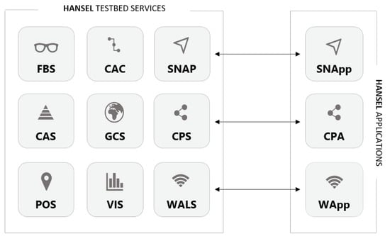
Figure 1.
HANSEL testbed high-level services scheme. Grey boxes in the set on the left represent Docker containers embedding the services running on the testbed server. The boxes included in the set on the right shows the three Android™ Applications with the links to the respective service.
All the services can be configured and monitored in real-time through the testbed url through a front-end service which provides a Graphic User Interface (GUI) for the whole framework, namely Front-end/Back-end Service (FBS).
4.1. Wi-Fi™ Access Point Location Service (WALS)
In order to exploit Wi-Fi™ routers for navigation it is necessary to know their location. Wi-Fi Access Point Location Service (WALS) is the service that ingests data points from an external application (described in further sections) and routinely computes those positions. Then, a rover receiver wishing to use a certain Wi-Fi Access Point (WAP) to navigate will query this service to know the location of this WAP. A system-level description of WALS is shown in Figure 2.
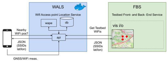
Figure 2.
High-level WALS (Wi-Fi Access Point Location Service) service description, showing the interaction of the service with the front-end.
This service can be understood as the equivalent of a GNSS orbits and clocks (ODTS) provider, but for Wi-Fi™.
The service has three main components:
- DB which stores: (a) The WAP positions and (b) both GNSS and Wi-Fi™ measurements;
- wape, a task that is routinely executed and whose sole purpose is to select a random WAP from the DB, fetch the most recent measurements associated to this WAP, and compute its position (that will be later stored in the DB);
- API the entry point of the service that will interface the external world.
The service is conceived to support indoor navigation of smartphones and mobile devices by relying on a pre-configured Wi-Fi™ network.
4.2. Command and Control Service (CAC)
This service provides the means to store the positions of the testbed users and track a user-defined route within the testbed in order to issue notifications on certain events (e.g., start, stop, accelerate, decelerate, etc.).
This service will be actually composed of two sub-services, as shown in Figure 3, one with the capabilities to upload and track certain paths (or routes), and another one that will control (monitor) the position of the user (within a path) and generate notifications to that user (command capabilities). Therefore, this service centralises all the positions computed by the other services or provided by the users/nodes interacting with the testbed.
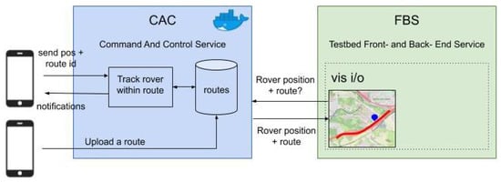
Figure 3.
High-level Command and Control service (CAC) service description, showing the interaction of the service with the front-end.
4.3. GNSS Orbit Visibility Service (VIZ)
The orbit service is in charge of providing the visibility status of the testbed in terms of GNSS satellites. It routinely fetches the most recent broadcast ephemeris that contains the orbital parameters for all satellites of the GPS, Galileo, Beidou, and GLONASS systems and generates the information to display the satellite visibility in terms of azimuth and elevation angles (so that a skyplot can be plotted). A skyplot can be generated according to any input reference position provided by the testbed operator or it can be generated according to the testbed location. The HANSEL testbed is indeed equipped with a high-end GNSS receiver to provide local observations and measurements from the testbed location.
This service allows also to override the broadcast ephemeris file fetched by the service in favour of other broadcast files provided by the user or SP3 files. In addition, while the visibility is computed in the location and local time of the testbed, other locations and epoch ranges can be specified.
4.4. JASON Based Positioning Relay Service (POS)
HANSEL offers to the testbed users the possibility to process GNSS data using Rokubun’s Jason Service ([49]) using the POS service (which is a relay service that interfaces with the Jason service in the cloud). Any user that has a set of GNSS measurements in the RINEX format can use this service to obtain an accurate navigation solution in post process using one of the following methods:
- Post-Processing Kinematics (PPK), which is the post-facto version of the Real Time Kinematic (RTK) differential technique. In this case, Jason will look and fetch the GNSS measurements from the closest reference GNSS station, chosen among a collection of more than 10,000 stations, spread among several public Continuous Operating Reference Station (CORS) networks;
- Precise Point Positioing (PPP). Depending on the age of the data set, a set of precise orbits and clocks (i.e., SP3 files from the International GNSS Service Analysis Centers) will be fetched instead of using the broadcast ephemeris. In current operations, PPP is only available after 1 or 2 weeks as it uses final products. This latency could be reduced to a few hours if ultra-rapid products were used instead.
Jason works on a best effort basis, trying to provide the best possible solution. If PPK cannot be performed (by e.g., closest reference station too far), PPP will be used instead. If everything else fails, a Single Point Positioing (SPP) solution will be provided.
4.5. GNSS Ntrip Caster (CAS) and GNSS Receiver Control Service (GCS)
The testbed includes a service that encapsulates a GNSS NTRIP caster from the Bundesamt für Kartographie und Geodäsie (BKG) ([50]). This caster streams the data from the testbed GNSS base receiver(s) to users that need to navigate accurately using RTK (who need GNSS measurements from reference receivers). In addition to the testbed receivers, this service allows also to relay already existing data from receivers that belong to other networks. The testbed NTRIP caster offers the sourcetable with a list of mountpoints in which the users of the testbed will be able to connect to.
Besides the caster service, the testbed has the GNSS Receiver Control service, that provide a means to monitor the status of the GNSS receivers of the testbed. Its API allows the front-end to provide a visual display in real time of the GNSS receiver status as well as timing information in different time-scales (i.e., local, GPS, GNSS, and UTC).
4.6. Snapshot Service (SNAP)
The framework implemented in the HANSEL testbed to support snapshot navigation applications envisages a near-real-time gathering and processing of raw GNSS measurements among a sensor network. These measurements are collected and sent asynchronously to a central computational facility built in Amazon Web Services (AWS), where the raw measurements are processed in order to obtain the desired information, typically the sensor position.
The SNAP service implemented in the HANSEL testbed provides the means to compute the sensor position by using three different technologies, namely GNSS, Cellular, and Hybrid (which combines GNSS and Cellular measurements) and to detect and locate present GNSS interferences within the sensor network. The central computational facility, aside from providing sensor/interference locations is also capable of supplying other valuable information such as the computed observables or the interference source relative emitting power.
The functional operation of the SNAP service relies on a master-slave approach, where the server collects all the requests generated by the users and stores them in a queue-like system. The built SNAP sensors contain a series of routines (SNApp) that allow them to autonomously collect the requests from the server and perform the required tasks. Being all the computational consuming processes performed in an independent cloud facility, added to the fact that the sensor-platform communication has been optimised to minimise bandwidth occupancy, the sensors have been proved to be low-power consuming devices with a long-lasting lifetime. A high-level service description can be seen in Figure 4.
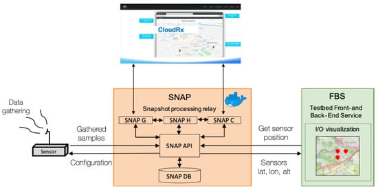
Figure 4.
High-level Snapshot Service (SNAP) service description, showing the interactions between the inner service components with the front-end.
The preliminary tests of the service have demonstrated that the platform is able to support hundreds of simultaneous connections, concurrently storing and processing requests. This was validated by means of a load test using an automated script that emulated virtual users logging into the system and launching requests/executions to the SNAP service. Users with a rate of one request/execution per minute were considered, to emulate a real-life sensor periodically requesting its position to the system. The CPU and memory load of the system was then monitored to make sure that no bottle necks were experienced as the number of users grew, and that the overall load did not degrade the performance of the rest of services running in the system. All the generated information is stored in a centralised database and easily accessible via a user-friendly interface, which allows the user to have complete knowledge about the network active devices and keep track of all the generated information.
4.7. Collaborative Positioning Service (CPS)
The framework implemented in the HANSEL testbed to support DGNSS-CP navigation and positioning algorithms foresees a near-real-time exchange of raw GNSS measurements among a set of Android™ smartphones. The devices integrate modern multi-constellation and multi-frequency GNSS chipsets and they are capable of communicating through a central node (i.e., the server running the services API). Such a node plays the role of a virtual channel and buffer between the users. Raw measurements obtained independently from each receiver are posted through a mobile application to a remote database to be downloaded by other users. A high-level scheme highlighting the data-flow and the component of the whole cooperative framework is shown in Figure 5.
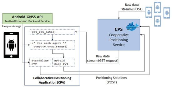
Figure 5.
High-level scheme of the cooperative framework foreseeing the exchange of GNSS raw measurements among Android™ smartphones through the Collaborative Positioning Service (CPS).
The CPS implemented in the HANSEL testbed provides a toolbox for the exchange of GNSS raw measurements through general purpose network connectivity such as Wi-Fi™ 802.11× or cellular networks (4G/LTE, 5G). The measurements are received by the CPS with a proper time stamp (aligned to the GNSS timescale) and they are stored locally for further analysis and future improved algorithms.
Preliminary analysis on the exchange of information between real network devices showed that the framework is capable of supporting near-real-time measurements exchange despite it being based on a client-server approach, non-real time operating systems, and non-ad-hoc links. Raw GNSS measurements can be effectively exchanged within the inter-epoch time of a receiver working at 1 Hz and a Extended Kalman Filter (EKF)-based tight integration scheme proposed in [51,52] can be beneficial to collaboratively improve estimation accuracy despite the possible delay introduced by the network and no error cancellation can be foreseen about these quantities. A delay in the transmission of data frames could actually affect the feasibility of an effective alignment of the asynchronous measurements sets, thus the availability of usable collaborative measurements. An inaccurate synchronisation of the local and external raw GNSS measurements can inject non-negligible biases in the baseline estimation. In the current implementation, if network latency between the agents exceeds the inter-epoch time of a given receiver, both the combination and integration of the collaborative measurements are inhibited to avoid additional errors in the position estimation. A rough time synchronisation provided by the independent PVT solutions of the smartphones w.r.t. the GNSS timescale, was hence assumed to achieve a reliable pseudorange differentiation [53,54]. By considering a reasonable latency on the network link (i.e., 50 ms), Doppler-based synchronisation has been demonstrated to be a suitable technique to achieve an accurate alignment of data [54].
By analyzing the data logged through two Xiaomi™ Mi 8 Pro, it has been assessed that the combination of raw data is feasible and regularly provided by smartphones with a measurement rate of 1 Hz (default value foreseen by Google™ API). The message format for the collaborative exchange of data has been defined to limit the bandwidth occupancy, and ensuring at the same time a simple interface. The API defined for the CPS can be used to download the data and test any collaborative navigation algorithm in post processing by exploiting local (aided agenti) and external (aiding agent) fixes and raw measurements.
4.8. Front-End/Back-End Service (FBS)
The Front-end and Back-end (i.e., FBS service) is hosted in the central server of the testbed. It is connected with every positioning service of the testbed and communicates with them in order to provide the necessary input data (input parameters, setup, etc.), as shown in the scheme in Figure 6. It also receives the output data of each service and processes it accordingly to the different application requirements (displaying data, configuration, and geographical information of services).
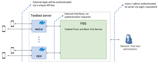
Figure 6.
Schema of the front-end role into the Hansel testbed.
The FBS is a graphical user interface to provide an easy, intuitive, and clean way of maintaining and configuring the services and visualising the output of each of them. Figure 7 shows a screenshot of the testbed dashboard summarizing on a map all the users of each service. FBS is fed from the data mainly from the API of each service depending on the particular characteristics of each of them. The API is responsible for the communication between the server and all services. It is bidirectional, being able to both, post and get data from and to the services.The front-end visualisation is customised to adapt to each particular service requirements.
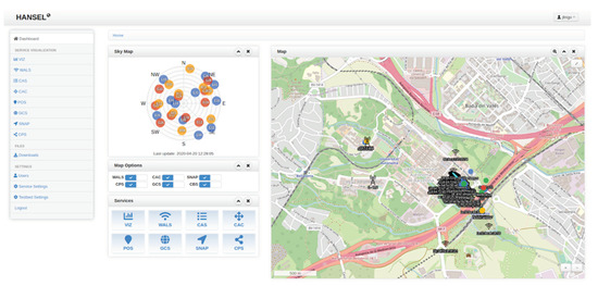
Figure 7.
Dashboard of the front-end showing the testbed map, satellite constellation, and shortcuts to all services.
FBS also provides a database service with all the information related with operators (i.e., authentication, permissions) and locations (geographical info, configuration). This allows the testbed operators to manage the testbed users and its usage permissions.
5. Hansel Mobile Applications
SNAP, CPS, and WALS are conceived to interact with their related mobile applications. All these services counterparts were developed for Android™ smartphones and their Android Package Kit (APK) are hosted by the central server of the testbed.
5.1. HANSEL App
The Hansel app serves two purposes:
- Demonstrate the capabilities of the WALS service in the context of Wi-Fi™ + GNSS hybridisation;
- Provide the means of interaction with the CAC service: Upload and follow routes and receive feedback from the testbed in the form of notifications.
In terms of the WALS demonstration, the terminal uses the GNSS and Wi-Fi™ RTT ranges for processing. The processing consists in the steps shown in Figure 8, summarised as follows:
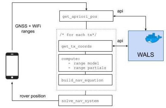
Figure 8.
Hansel app is used to demonstrate the Wi-Fi™+ GNSS hibridisation.
- Get the apriori coordinates the terminal (i.e., receiver). This apriori may come from the terminal itself (coarse cell position) or, if not provided, by an average of the positions of nearby WAP (Wi-Fi™ Access Points) seen by the terminal. If in the latter case, the app shall fetch these positions using the WALS API;
- Get the coordinates for each transmitter that is provided in the data packet (which contains the ranges). If the transmitter is a GNSS satellite, use the orbit provider (broadcast file, SP3 file, etc.). If the transmitter is a WAP (Wi-Fi™ Access Point), a query is sent to the WALS service;
- Compute the range models and partials. The range model will depend on the transmitter type (e.g., for GNSS the atmospheric delays, relativity, etc.)
- Use the computed range and partials to build the navigation equations;
- Solve the navigation equations and obtain the estimate of the rover position.
In terms of CAC, the Hansel app allows the user to upload a route (or path) to the server. This route can be later followed by the same user or other users in the testbed. When a route is followed, the app sends the position every second and the testbed checks if the position is within the boundaries of the route and notifies the user if the position is within boundaries. In addition, the route can be timed which means that not only is the position checked but also if the user is in the position at a certain expected time. This facility can be used in future to check the velocity of the user for applications such as platooning.
5.2. SNApp
The SNAP service makes possible the sensor-to-platform communication via a dedicated Application Programming Interface (API), which defines a series of predefined requests to interact with the service core facility. Routines for the sensor to execute these requests are integrated in a software package called SNAP Application (SNApp), installed in all the SNAP sensors. The software package is responsible for the following actions:
- Asynchronous configuration of the sensor parameters;
- Retrieve jobs/requests;
- Record live RF signals;
- 1-bit compression to reduce the size of the recorded signal file;
- Transmission of the recorded signal file to the cloud platform for its processing.
SNApp has been designed as an easily-installable software package conceived for sensors to interact with the SNAP API in a secure and autonomous manner. The software is also responsible for the manipulation of the sensor hardware, namely a RF front-end based in a Software Defined Radio (SDR) device, whose main purpose is to gather live RF signals, and a UNIX-based control board responsible for data forwarding over a wireless connection. A prototype of hardware sensor was developed in course of the HANSEL project and the details can be found in [55]. The routines implemented within SNApp are designed to support sensors implementing any SDR-based device, as long as its hardware configuration is properly set (i.e., sampling frequency, bit encoding, etc.). The SNApp routines are entirely implemented in Python and require the sensor control board to install Python v3.0 or higher. In our case, a Raspberry Pi Zero W [56] was used to run the SNApp routines controlling a RTL-SDR RF front end [57] and to provide Wi-Fi™ connectivity for delivering the gathered RF samples to the cloud platform.
5.3. Collaborative Positioning Application (CPA)
CPS main functionality is exercised through the API by the Collaborative Positioning Application (CPA), a scientific research-oriented Android™ application including the core algorithm for a collaborative DGNSS-based CP.
The app is conceived to perform the following set of actions:
- Negotiate the registration of smart devices to the service;
- Upload and download the GNSS raw measurements and positioning data shared by registered agents. The measurements exchange exploits User Datagram Protocol (UDP) protocol to limit the transmission delay through the possible network nodes;
- Perform a rough GNSS-only PVT solution to synchronise asynchronous measurements downloaded by means of the CPS;
- Compute the inter-agent distance by means of Double Differentiation of the pseudorange measurements retrieved w.r.t. to a set of common satellites;
- Perform the post-processing of GNSS and collaborative measurements through Bayesian EKF-based tight-integration, thus providing both GNSS-only and hybrid positioning solutions for a consistent performance self-assessment;
- Internally log the reference position estimation provided by the Google™ Fused Location Provider (GFLP);
- Store locally and upload to the testbed the output files generated during its operational timespan.
The CPA is conceived as a mobile application running on GNSS-raw-measurements-ready Android™ mobile devices and interacting with other agents through the CPS. It is designed as a Proof Of Concept (PoC) of the GNSS-based collaborative positioning. Multiple instances of the CPA (installed in a set of independent smartphones) are expected to interact with the CPS by means of the CPS API to take advantage on the aforementioned paradigm. The app is natively implemented in Java, using the Android™ Studio environment. The CPA requires at least API level 27 (Android™ 8, or more recent) to provide full support to the public class GNSSMeasurements. CPA also implement CAC functionality, thus being able to receive real-time feedbacks about pre-defined test trajectories.
The testbed architecture was proven to be a valuable central-node for real-time constrained cooperative positioning, being a buffer and data dispatcher for networked smartphones operating CPA instances.
6. Test Campaigns and Results
A set of meaningful results are collected hereafter from the HANSEL test campaigns performed during the project. For each tested technology the experimental setup is contextually described.
6.1. SNAP Positioning
A series of tests have been performed in order to assess the performance of the SNAP service in its three positioning modes: Standalone GNSS, standalone cellular, and hybrid GNSS + cellular.
6.1.1. Material and Experimental Setup
A prototype hardware sensor based on a Raspberri Pi™ Zero W and a RTL-SDR RF front end was used, controlled by the SNApp routines to manage the signal capture and transmission to the processing platform.
Live GPS L1 signals were gathered using a Cirocomm 580 GPS L1 antenna incorporated into the hardware sensor, and the RF front end was configured at a MHz bandwidth. The location of the ground truth position was surrounded by middle height buildings so that the live signal captures could be representative of a middle-size city. The snapshot length of the recorded GPS L1 signal was 20 ms. Cellular signals were simulated using the embedded 4G simulator of the SNAP service in order to circumvent the limitations of existing live cellular signals. Namely, the lack of precise knowledge on the base station (BS) positions, which becomes sensitive information that telecom operators are reluctant to release, as well as the lack of precise synchronisation between different BS. Note that BS are typically synchronised in cellular deployments to prevent inter-cell interference and to implement power-control mechanisms. However, this synchronisation is not perfect and small errors appear from one BS to another. These errors, being much smaller than in a purely asynchronous network, are accounted for into the embedded 4G simulator so that realistic results can be obtained.
A virtual deployment of four 4G BS was configured in the SNAP cellular simulator, which were all set in the surroundings of the user’s true reference position at 500 of inter BS separation. A urban macro (UMa) scenario was considered with 4G Positioning Reference Signals (PRS) of a 20 MHz bandwidth that were used by the simulator to provide OTDoA observables (one per BS and per position fix). The LOS conditions were determined based on the distance-dependent LOS probability as specified in TR 38.855 [58] while the SNR of each observable was computed with a 3GPP-like link budget [59]. Then the cellular ranging observables were generated following a physical-layer abstraction [60] using as input the LOS conditions and the SNR level. Finally, a 50 ns synchronisation error was also considered to emulate a synchronised (but not perfectly) network of 4G base stations.
6.1.2. Position Accuracy
Results are shown in Figure 9 for the Cumulative Density Function (CDF) of the 2D horizontal errors obtained with each of the three positioning modes of the SNAP service. Vertical errors were not considered in this experiment because the target application was that of positioning a user in a 2D city map, and thus vertical information was disregarded. Position errors were 95% of the time below 100 for GPS L1 position fixes with a median error of 40 , while for cellular position fixes they were below 45 m with a median error of 12 . When hybridising both GPS L1 observables and cellular observables, 2D horizontals errors went down to roughly 25 95% of the time, thus highlighting the convenience of combining different technologies in urban scenarios.
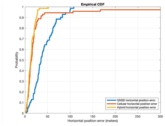
Figure 9.
Cumulative Density Function (CDF) of the 2D horizontal position errors obtained by the SNAP sensors using GNSS and cellular signals either in standalone mode or hybridised in a representative working scenario.
The results in Figure 9 are a good example on how GNSS accuracy can be improved in urban areas by relying on additional positioning technologies. This helps in mitigating situations where GNSS observables are not available, as it happens due to signal blockage by high buildings, and thus it provides an additional degree of robustness. There are two research directions where efforts could be placed for evolving the current SNAP service. The first one would be to process signals from multiple GNSS constellations (e.g., GPS, Galileo, and Beidou, which share the same band) and combine them to obtain a multi-constellation position fix. This would greatly improve the availability in urban areas due the much larger number of available satellites in the sky. The second research direction would be to expand the hybridisation algorithm of the SNAP service to consider additional technologies apart from cellular signals. The use of information coming from inertial sensors, barometers and signals of opportunity such as DVB-T/-S can certainly improve the reliability and accuracy of the user’s position [61]. Interestingly, combining several technologies does also contribute to strengthening the level of trust of the obtained position fix, since each technology is independent from one another and thus difficult to hack or to counterfeit at the same time. Securing and authenticating the user’s position is definitely an interesting research topic to explore [62].
6.2. Wi-Fi™ RTT Ranging
6.2.1. Material and Experimental Setup
In the context of data processing of Wi-Fi™ RTT measurements, the quality of the measurements has been assessed, using the setup shown in Figure 10. In particular, two criteriums were used to characterise the Wi-Fi™ RTT measurements:
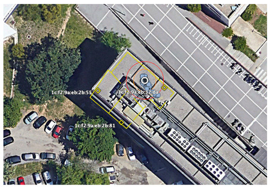
Figure 10.
Setup for the Wi-Fi™ RTT (Round Travel Time) experimentation in the HANSEL project. Yellow dots corresponds to the position of the WiFi Access Points, the white circle is the location of the smartphone, yellow and red circles are reference lines at 3 and 5 m, and blue points are the positioning solution using WiFi only.
- Variability of the measurements under static conditions (i.e., observable noise);
- Potential biases, that could be related to the WAP and/or device.
To conduct this quality assessment, a Google™ Pixel 2 smartphone was placed at an exactly well known (measured) distance relative to 3 Google™ Wi-Fi™ routers. With this setup, several data-takes were taken and analysed. Figure 11 shows the RTT ranges minus the actual range (measured with the measuring tape). In an ideal case, this difference should yield a constant 0 with a certain noise. The plot evidences a certain bias that is router dependent (see the bias values for each router MAC address in the figure) but might as well depend on the smartphone. These biases will directly impact the performance of a potential navigation solution based on RTT.
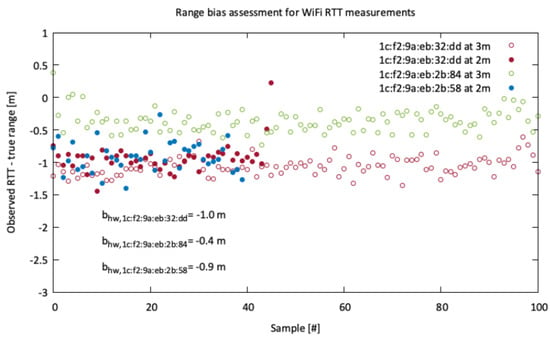
Figure 11.
Bias estimation of the RTT measurements for the 3 Wi-Fi™ routers and Google™ Pixel 2.
In addition to the biases, the noise of these ranges might be derived from this test. Note that the tests have been performed under a benign environment, where no nearby objects or bodies were present and thus the multipath patterns might be minimised. Under these circumstances, the standard deviation of the RTT time series for the 3 routers amount to ca. 20 cm.
Knowing the standard deviation (i.e., noise) of the measurements will be of relevance when setting up the parameters and configuration of the navigation filter it is based on e.g., Kalman filter. Under real conditions, the weighting of the measurements within the Kalman filter can be performed using either the RTT error measurement given by the Android API, the RSS (prioritising those measurements with higher received power), or a combination of both. However, under ideal cases a theoretical accuracy using RTT of 20 cm (driven by the RTT noise) could be in principle achieved. This is inline with previous works (see for instance [33]).
In addition to the Wi-Fi™ RTT measurement quality, the WALS service and Hansel app have been used to test and demonstrate the capability of the algorithms developed in the testbed to perform purely indoor positioning using only Wi-Fi™ RTT measurements (no GNSS data) and the known locations of the WAPs.
The data collection was done on the 25 February 2020 at the OpenLab of the UAB campus, where several Google™ Wi-Fi™ routers were deployed. The data collection was performed using the Google™ Pixel 2 smartphone of the project for roughly 20 min, placed on a table in the main room of the OpenLabs.
6.2.2. Position Accuracy and Precision
Albeit not having a true reference location of the smartphone, a first quality assessment of the positioning solution could be based on the standard deviation of the East/North/Up (ENU) components relative to the average position of the time series. The time series of the ENU components are shown in Figure 12.
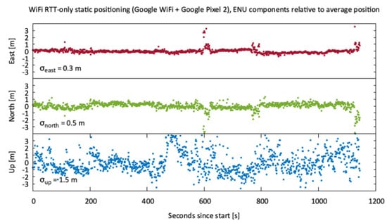
Figure 12.
East/North/Up components of the Wi-Fi™ RTT position estimates relative to the average position of the smartphone (in static). Standard deviation of each component is also included in the plot.
It can be seen that, under optimal conditions (static device with no nearby obstructions), the precision of the solution of / / in ENU respectively can be achieved. As expected, the North component is the one performing the worst due to a similar reason as in GNSS, the Dilution of Precision (DOP): All routers were placed at the same height as the device. If the WAP were located at different heights (providing more geometric diversity in the height component), the precision of the Up component would also be improved.
Albeit Wi-Fi™ RTT ranging can be a potential solution to provide indoor navigation capabilities, its main limitation, as of today, is scalability. This limitation stems from the RTT range measurements side because 802.11mc is a bi-directional protocol and therefore a high number of simultaneous users performing the RTT query might clog the router. There are already various works trying to overcome this limitation in order to convert WiFi routers closest to a one-way navigation system such as GNSS (see for instance [63]). On the testbed side (i.e., data-management side provided by WALS), there is no limitation on the number of users because the container can be replicated in mirror servers as the number of users increase.
6.3. DGNSS-Based Cooperative Positioning
Concerning CPS and CPA, baseline computation tests were initially performed to check the consistency of the information propagated by the smartphones through the network [54]. Two test-campaigns have been performed afterwards by relying on different networks and infrastructure:
- Turin-to-Dublin (TRN-DUB) co-located agents (i.e., Politecnico di Torino Campus, Turin, Italt) and remote testbed running on an AWS™ (Dublin, Ireland), trough 4G/LTE cellular connectivity;
- Barcelona-to-Barcelona (BRC-BRC) co-located agents and testbed (i.e., Universitat Autònoma de Barcelona (UAB) campus, Barcelona, Spain), trough 4G/LTE cellular connectivity.
6.3.1. Material and Experimental Setup
The following results and comments concern the use of two Xiaomi Mi 8 Pro smartphones referred to as Sm01 and Sm02, for which a pairwise cooperation was reciprocally ensured through the proposed framework. The devices were running Android™ 10 Q and Dual Frequency GNSS receiver embedded in the Broadcom BCM47755 chipset, enabled to guarantee access to both raw GNSS measurements and GFLP reference position estimates. The data transfer to the CPS was peformed through 4G/LTE civil networks locally available at the tests locations.
6.3.2. Service Availability
The availability of such a near-real-time service was measured as the ratio between the number of actual cooperations and total number of positioning solutions. Such a metric was strictly related to the congestion status of the network. Non-ideal links indeed can limit upload/download channel capacity of the raw GNSS measurements to/from the CPS database, thus making their combination unfeasible.
As observed in the test campaigns, a considerable availability of the service (higher than 75%) was experienced in the morning test sessions. Differently, late morning experiments showed a progressively decreasing availability. By comparing the results with the preliminary test campaign (TRN-DUB), it can be observed that the service availability of the experiments performed during the UAB test campaign (UAB-UAB) is lower on average. Sm01 and Sm02 tested in Turin showed an average availability of 86.96% and 81.23% respectively, while these values were dramatically reduced in the UAB test campaign. By considering only the set of best-case experiments, we observed an average availability of 74.28% (sm01) and 78.35% (sm02), which is still lower than the aforementioned values observed in TRN-DUB, but still acceptable and similarly promising.
6.3.3. Service Profitability and Accuracy Improvement
The actual benefit provided by the proposed collaborative framework can be observed in terms of reduction of the position Mean Squared Error (MSE) w.r.t. the standalone GNSS solution, namely profitability.
It accounts for the percentage of epochs in which the hybrid solution provided a better estimate (lower MSE) than the GNSS-only solution, both compared to the GFLP (self-assessed through the CPA). Figure 13 presents a qualitative view of the promising amount of profitable epochs in a sample experiments at UAB campus. Figure 14 shows the 3D profitability of the experiments belonging to each test campaign.
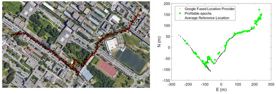
Figure 13.
Sample pedestrian trajectory across UAB Campus showing on the left the GFLP solution in red and GNSS standalone fixes in black (BRC-BRC campaign). On the right, the East/North reference frame highlights the profitable epochs in which DGNSS-CP (Cooperative Positioning) improved the positioning solution of more than the 10% in accuracy.
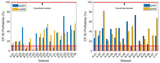
Figure 14.
Collaborative positioning 3D profitability from pairwise cooperation of two Xiaomi Mi8 Pro running independent CPA (Collaborative Positioning Application) instances. TRN-DUB Test campaign on the left and BRC-BRC Test campaign on the right. The lower red line identifies the minimum validation criteria w.r.t. the overall test duration (upper red line).
Profitability was actually normalised w.r.t. to the number of epochs in which cooperation was been successfully performed. A considerable subset of experiments overcame the validation criteria (profitability higher than the 10%) both in 2D and 3D MSE. For what concerned the profitability, the results obtained during the BRC-BRC test campaign are comparable with the results retrieved in the TRN-DUB campaign. This assessed the performance improvement which can be provided through the proposed paradigm, by considering a single aiding agent in a pairwise cooperation.
Pairwise cooperation was hence assessed to be effective and profitable with an accuracy improvement overcoming the 10% for more than the 25% of the test timespan. The actual mean profitability values computed over all the experiments were indeed % (Sm01) and % (Sm02) in 3D profitability campaign, and % (Sm01) and % (Sm02) for 3D profitability.
Such preliminary findings in non-ideal network and visibility conditions for both the devices makes DGNSS-CP a promising technology for mass-market devices and receivers in urban and mild-urban scenarios.
The implementation of the proposed DGNSS-CP paradigm also assessed the feasibility of a passive, pass-through node i.e., CPS integrated in the testbed making it relevant to the service itself. A limitation is that the actual CP service cannot be distributed among the connected devices and despite being centralised, it does not currently implement any logic for the selection of optimal collaborative contributions (also known in multi-agent-related literature as information censoring).
7. Conclusions
A Smart City requires an intelligent infrastructure to serve its urban area with heterogeneous services and applications. Today, such an infrastructure is essentially composed of three main layers. The perception layer, implemented by means of IoT, senses and interacts with the environment and collects and consumes data and information and data flows back and forth through smart gateways to the network layer. This latter interconnects the IoT with the back-end processing technologies. The network layer today is augmented with edge computing capabilities to pre-processing, cross-reference, and fuse data, to create a preliminary distributed intelligence able to interact with the perception layers and with high performance computing elements in the cloud. The application layer is finally responsible to analyse massive data and preliminary information by means of intelligent technologies [64]. Several elements of this infrastructure and the end-users (very often IoT themselves such as smartphones, vehicles, etc.) require precise location and timing information. GNSS is the natural enabler to satisfy these needs, through its global coverage and free of charge provision of location data but it is not the sole ingredient. The HANSEL project, while developing a testbed for diverse positioning and navigation technologies presented in this manuscript, has designed, developed, and tested an architecture (for positioning and timing services) that easily fit in the aforementioned Smart City infrastructure by adding relevant value. Indeed, the HANSEL architecture, once integrated in a Smart City, can be augmented with new services in a scalable fashion. The architecture is made of interoperable micro-services with standard interfaces and format. The proposed approach deviates from a monolithic philosophy and adopts a scalable attitude that allows Smart City architects to split it over the three layers of infrastructure. Microservices constitutes an architectural style structuring services and applications as a collection of (smaller) services that are highly maintainable, testable, and traceable. These microservices can be deployed independently, which reverts to greater flexibility, thus allowing better organisation around different business capabilities and use cases.
The HANSEL testbed provides a framework to gather navigation data retrieved from heterogeneous and asynchronous devices (i.e., IoT Sensors, Smartphones, and general purpose GNSS receivers). In parallel it levarages a scientific tool to investigate and support research and development of GNSS state-of-the-art and innovative technologies through a uniform multi-services system.
The framework is conceived as a centralised entity that collects data from different services by covering in turn different applications and case studies. All HANSEL services are designed to be interoperable and the service APIs can be exploited through mobile applications running on smart devices or more sophisticated tools. Currently, the service interoperability is foreseen for the CAC and CPA only. The mobile application supporting the DGNSS-CP paradigm is indeed capable of interacting with the CAC to be moniotored and retrieve navigation tips (e.g., turn left, turn right, out of path) based on the hybrid PVT solution computed through cooperation with other agents. Interoperability deserves to be ensured for all the service to support future hybridisations of the available technologies.
The development and first validation of such an architecture is an important result, no less important than having built the testbed itself because it represents a concrete and viable solution that could overcome limitations of many technologically-advanced solutions on the market today, namely the verticality, the impossibility of reuse, and their vendor lock-in nature, which allows only the manufacturers to pursue upgrades and plan technologies or products evolution.
Furthermore, improved algorithms are expected to be implemented regarding snapshot processing, Wi-Fi™ ranging, and CP and additional GNSS technologies deserve to be integrated in the future release of the HANSEL testbed. The testbed could host future technologies and it can be easily cloned to support on-field test campaigns for innovative solutions to positioning and navigation in Smart Cities. A natural follow-up of the project could address the autonomous guidance within a smart city environment as approached by the proposed CAC service, by gathering new ground-breaking PNT technologies specifically supporting autonomous mobility in urban scenarios.
Author Contributions
Conceptualization, A.M., F.D., A.V., M.G.-F., À.L.-C., J.L.T., M.M., A.P.-C., G.S.-G. and J.A.L.-S.; Data curation, A.M., M.G.-F., J.G.-F. and J.A.L.-S.; Formal analysis, A.M., M.G.-F., À.L.-C. and J.G.-F.; Funding acquisition, M.G.-F. and J.A.L.-S.; Investigation, A.M., M.G.-F., G.S.-G. and J.A.L.-S.; Methodology, A.M., M.G.-F., À.L.-C., A.P.-C. and J.A.L.-S.; Project administration, F.D., M.G.F., M.M. and J.A.L.-S.; Resources, À.L.-C.; Software, A.M., À.L.-C., J.L.T., A.P.-C., J.G.-F. and J.A.L.-S.; Supervision, M.G.-F., À.L.-C. and G.S.-G.; Validation, À.L.-C.; Visualization, A.M. and M.M.; Writing—original draft, A.M., F.D., A.V., M.G.-F., À.L.-C., J.L.T., M.M., A.P.-C., J.G.-F. and J.A.L.-S.; Writing—review & editing, A.M., F.D., M.G.-F., À.L.-C., M.M. and J.A.L.-S. All authors have read and agreed to the published version of the manuscript.
Funding
The testbed presented in this paper was designed, developed and tested in the context of HANSEL (ESA ITT number AO/1-9494/18/NL/CRS), a project founded by the European Space Agency (ESA) and led by Rokubun S.L. The authors acknowledge ESA, the Project Officer, Rui Sarnadas, and all partners of the HANSEL consortium.
Acknowledgments
The testbed presented in this paper was designed, developed, and tested in the context of HANSEL, an ESA funded Technology Research Programme (TRP) activity. The authors would like to acknowledge European Space Agency (ESA) and all the partners of the HANSEL consortium.
Conflicts of Interest
The authors declare no conflict of interest.
Disclaimer
The content of the present article reflects solely the authors’ view and by no means represents the official view of the European Space Agency (ESA). In any reproduction of this article there should not be any suggestion that ESA or this article endorse any specific organisation or products. The use of the ESA logo is not permitted. This notice should be preserved along with the article’s original URL.
References
- Brundtland, G.H. World commission on environment and development. Environ. Policy Law 1985, 14, 26–30. [Google Scholar]
- ENoLL Office. European Network of Living Labs; ENoLL Office: Brussels, Belgium, 2020. [Google Scholar]
- Leydesdorff, L.; Deakin, M. The triple-helix model of smart cities: A neo-evolutionary perspective. J. Urban Technol. 2011, 18, 53–63. [Google Scholar] [CrossRef]
- Carayannis, E.G.; Campbell, D.F. ‘Mode 3’ and ‘Quadruple Helix’: Toward a 21st century fractal innovation ecosystem. Int. J. Technol. Manag. 2009, 46, 201–234. [Google Scholar] [CrossRef]
- Stratigea, A.; Leka, A.; Panagiotopoulou, M. In search of indicators for assessing smart and sustainable cities and communities’ performance. In Smart Cities and Smart Spaces: Concepts, Methodologies, Tools, and Applications; IGI Global: Hershey, PA, USA, 2019; pp. 265–295. [Google Scholar]
- Stimmel, C.L. Building Smart Cities: Analytics, ICT, and Design Thinking; CRC Press: Boca Raton, FL, USA, 2015. [Google Scholar]
- Vesco, A. Handbook of Research on Social, Economic, and Environmental Sustainability in the Development of Smart Cities; IGI Global: Hershey, PA, USA, 2015. [Google Scholar]
- GSA. Market Report Issue 6; European Global Navigation Satellite Systems Agency (GSA): Prague, Czech Republic, 2019. [Google Scholar]
- Petcovici, A.; Stroulia, E. Location-based services on a smart campus: A system and a study. In Proceedings of the 2016 IEEE 3rd World Forum on Internet of Things (WF-IoT), Reston, VA, USA, 12–14 December 2016; pp. 94–99. [Google Scholar]
- Tadic, S.; Favenza, A.; Kavadias, C.; Tsagaris, V. GHOST: A novel approach to smart city infrastructures monitoring through GNSS precise positioning. In Proceedings of the 2016 IEEE International Smart Cities Conference (ISC2), Trento, Italy, 12–15 September 2016; pp. 1–6. [Google Scholar]
- Usman, M.; Asghar, M.R.; Ansari, I.S.; Granelli, F.; Qaraqe, K.A. Technologies and Solutions for Location-Based Services in Smart Cities: Past, Present, and Future. IEEE Access 2018, 6, 22240–22248. [Google Scholar] [CrossRef]
- Li, D.; Shan, J.; Shao, Z.; Zhou, X.; Yao, Y. Geomatics for Smart Cities–Concept, Key Techniques, and Applications. Geo-Spat. Inf. Sci. 2013, 16, 13–24. [Google Scholar] [CrossRef]
- Yin, L.; Ni, Q.; Deng, Z. A GNSS/5G Integrated Positioning Methodology in D2D Communication Networks. IEEE J. Sel. Areas Commun. 2018, 36, 351–362. [Google Scholar] [CrossRef]
- Cui, X.; Gulliver, T.A.; Li, J.; Zhang, H. Vehicle Positioning Using 5G Millimeter-Wave Systems. IEEE Access 2016, 4, 6964–6973. [Google Scholar] [CrossRef]
- Dovis, F.; Ruotsalainen, L.; Toledo-Moreo, R.; Kassas, Z.Z.M.; Gikas, V. Recent Advancement on the Use of Global Navigation Satellite System-Based Positioning for Intelligent Transport Systems [Guest Editorial]. IEEE Intell. Transp. Syst. Mag. 2020, 12, 6–9. [Google Scholar] [CrossRef]
- Lin, X.; Bergman, J.; Gunnarsson, F.; Liberg, O.; Razavi, S.M.; Razaghi, H.S.; Rydn, H.; Sui, Y. Positioning for the Internet of Things: A 3GPP Perspective. IEEE Commun. Mag. 2017, 55, 179–185. [Google Scholar] [CrossRef]
- Lucas-Sabola, V.; Seco-Granados, G.; López-Salcedo, J.A.; García-Molina, J.A.; Crisci, M. Cloud GNSS receivers: New advanced applications made possible. In Proceedings of the 2016 International Conference on Localization and GNSS (ICL-GNSS), Barcelona, Spain, 28–30 June 2016; pp. 1–6. [Google Scholar] [CrossRef]
- Yoon, D.; Kee, C.; Seo, J.; Park, B. Position Accuracy Improvement by Implementing the DGNSS-CP Algorithm in Smartphones. Sensors 2016, 16, 910. [Google Scholar] [CrossRef]
- de Ponte Muller, F.; Diaz, E.M.; Kloiber, B.; Strang, T. Bayesian cooperative relative vehicle positioning using pseudorange differences. In Proceedings of the IEEE/ION Position, Location and Navigation Symposium—PLANS 2014, Monterey, CA, USA, 5–8 May 2014; pp. 434–444. [Google Scholar]
- Frattasi, S.; Della Rosa, F. Mobile Positioning and Tracking: From Conventional to Cooperative Techniques; John Wiley & Sons: Hoboken, NJ, USA, 2017. [Google Scholar]
- Sand, S.; Dammann, A.; Mensing, C. Positioning in Wireless Communications Systems; John Wiley & Sons: Hoboken, NJ, USA, 2014. [Google Scholar]
- des Dorides, C. How Space Technologies Are Driving the Future of Smart Cities; GSA: London, UK, 2018.
- European Global Navigation Satellite Systems Agency (GSA) Satellites and the City; GSA: Prague, Czech Republic, 2019.
- Jensen, A.B.O.; Thomsen, P.L.; Larsen, S.S. Testbed Enables Infrastructure for Autonomy, Smart Cities; GPS World, North Coast Media: Cleveland, OH, USA, 2020. [Google Scholar]
- Mekki, K.; Bajic, E.; Chaxel, F.; Meyer, F. Overview of Cellular LPWAN Technologies for IoT Deployment: Sigfox, LoRaWAN, and NB-IoT. In Proceedings of the IEEE International Conference on Pervasive Computing and Communications, Athens, Greece, 19–23 March 2018; pp. 197–202. [Google Scholar]
- European Global Navigation Satellite Systems Agency (GSA). Power-Efficient Positioning for the Internet of Things; GSA: Prague, Czech Republic, 2020.
- Paek, J.; Kim, J.; Govindan, R. Energy-Efficient Rate-Adaptive GPS-Based Positioning for Smartphones. In Proceedings of the International Conference on Mobile Systems, Applications, and Services (MobiSys); Association for Computing Machinery: New York, NY, USA, 2010; pp. 299–314. [Google Scholar]
- Dao, T.K.; Nguyen, H.L.; Pham, T.T.; Castelli, E.; Nguyen, V.T.; Nguyen, D.V. User localization in complex environments by multimodal combination of GPS, WiFi, RFID, and pedometer technologies. Sci. World J. 2014, 2014, 814538. [Google Scholar] [CrossRef]
- Lucas-Sabola, V.; Seco-Granados, G.; López-Salcedo, J.A.; García-Molina, J.A. GNSS IoT Positioning: From Conventional Sensors to a Cloud-Based Solution. Inside GNSS 2018, 3, 53–62. [Google Scholar]
- Zhu, X.; Feng, Y.; others. RSSI-based algorithm for indoor localization. Commun. Netw. 2013, 5, 37. [Google Scholar] [CrossRef]
- Schauer, L.; Dorfmeister, F.; Maier, M. Potentials and limitations of wifi-positioning using time-of-flight. In Proceedings of the International Conference on Indoor Positioning and Indoor Navigation, Montbeliard-Belfort, France, 28–31 October 2013; pp. 1–9. [Google Scholar]
- IEEE Standards Association. IEEE Standard for Local and Metropolitan Area Networks—Part 11: Wireless LAN Medium Access Control (MAC) and Physical Layer (PHY) Specifications; IEEE Std 802.11-2016; IEEE: Piscataway, NJ, USA, 2016. [Google Scholar]
- van Diggelen, F.; Want, R.; Wang, W. How to Achieve 1-Meter Accuracy in Android. 2018. Available online: https://www.gpsworld.com/how-to-achieve-1-meter-accuracy-in-android/ (accessed on 8 October 2018).
- Horn, B.K. Doubling the Accuracy of Indoor Positioning: Frequency Diversity. Sensors 2020, 20, 1489. [Google Scholar] [CrossRef]
- Wi-Fi Location: Ranging with RTT. 2020. Available online: https://developer.android.com/guide/topics/connectivity/wifi-rtt (accessed on 28 August 2020).
- Mourikis, A.I.; Roumeliotis, S.I. Performance analysis of multirobot Cooperative localization. IEEE Trans. Robot. 2006, 22, 666–681. [Google Scholar] [CrossRef]
- Roumeliotis, S.I.; Bekey, G.A. Distributed multirobot localization. IEEE Trans. Robot. Autom. 2002, 18, 781–795. [Google Scholar] [CrossRef]
- Dardari, D.; Falletti, E.; Luise, M. Satellite and Terrestrial Radio Positioning Techniques: A Signal Processing Perspective; Academic Press: Cambridge, MA, USA, 2012. [Google Scholar]
- Gao, C.; Zhao, G.; Fourati, H. Cooperative Localization and Navigation: Theory, Research, and Practice; CRC Press: Boca Raton, FL, USA, 2019. [Google Scholar]
- Banville, S.; Van Diggelen, F. Precise positioning using raw GPS measurements from Android smartphones. GPS World 2016, 27, 43–48. [Google Scholar]
- Sheta, A.; Mohsen, A.; Sheta, B.; Hassan, M. Improved Localization for Android Smartphones Based on Integration of Raw GNSS Measurements and IMU Sensors. In Proceedings of the 2018 International Conference on Computer and Applications (ICCA), Beirut, Lebanon, 25–26 August 2018; pp. 297–302. [Google Scholar] [CrossRef]
- Dabove, P.; Pietra, V.D. Towards high accuracy GNSS real-time positioning with smartphones. Adv. Space Res. 2019, 63, 94–102. [Google Scholar] [CrossRef]
- Xiong, J.; Cheong, J.W.; Xiong, Z.; Dempster, A.G.; Tian, S.; Wang, R. Integrity for Multi-Sensor Cooperative Positioning. IEEE Trans. Intell. Transp. Syst. 2019, 1–16. [Google Scholar] [CrossRef]
- Ansari, K.; Feng, Y.; Tang, M. A Runtime Integrity Monitoring Framework for Real-Time Relative Positioning Systems Based on GPS and DSRC. IEEE Trans. Intell. Transp. Syst. 2015, 16, 980–992. [Google Scholar] [CrossRef]
- Gogoi, N.; Minetto, A.; Dovis, F. On the Cooperative Ranging between Android Smartphones Sharing Raw GNSS Measurements. In Proceedings of the VTC2019-Fall Honolulu Intelligent Connection and Transportation), Honolulu, HI, USA, 22–25 September 2019. [Google Scholar]
- Alam, N.; Tabatabaei Balaei, A.; Dempster, A.G. Relative Positioning Enhancement in VANETs: A Tight Integration Approach. IEEE Trans. Intell. Transp. Syst. 2013, 14, 47–55. [Google Scholar] [CrossRef]
- Liu, K.; Lim, H.B.; Frazzoli, E.; Ji, H.; Lee, V.C.S. Improving Positioning Accuracy Using GPS Pseudorange Measurements for Cooperative Vehicular Localization. IEEE Trans. Veh. Technol. 2014, 63, 2544–2556. [Google Scholar] [CrossRef]
- Minetto, A.; Dovis, F. On the Information Carried by Correlated Collaborative Ranging Measurements for Hybrid Positioning. IEEE Tran. Veh. Technol. 2019, 69, 1419–1427. [Google Scholar] [CrossRef]
- Jason. GNSS Data Processor in the Cloud. 2020. Available online: https://jason.rokubun.cat (accessed on 28 August 2020).
- BKG Professional NtripCaster (Linux, v2.0.36). 2020. Available online: https://igs.bkg.bund.de/ntrip/bkgcaster (accessed on 28 August 2020).
- Minetto, A.; Nardin, A.; Dovis, F. Tight Integration of GNSS Measurements and GNSS-based Collaborative Virtual Ranging. In Proceedings of the 31st International Technical Meeting of the Satellite Division of the Institute of Navigation (ION GNSS+ 2018), Miami, FL, USA, 25–28 September 2018; pp. 2399–2413. [Google Scholar] [CrossRef]
- Minetto, A.; Nardin, A.; Dovis, F. GNSS-only Collaborative Positioning Among Connected Vehicles. In Proceedings of the 1st ACM MobiHoc Workshop on Technologies, mOdels, and Protocols for Cooperative Connected Cars; TOP-Cars ’19; ACM: New York, NY, USA, 2019; pp. 37–42. [Google Scholar] [CrossRef]
- Hasan, K.F.; Feng, Y.; Tian, Y. GNSS Time Synchronization in Vehicular Ad-Hoc Networks: Benefits and Feasibility. IEEE Trans. Intell. Transp. Syst. 2018, 19, 3915–3924. [Google Scholar] [CrossRef]
- De Ponte Müller, F.; Steingass, A.; Strang, T. Zero-Baseline Measurements for Relative Positioning in Vehicular Environments. In Proceedings of the 6th European Workshop on GNSS Signals and Signal Processing, Munich, Germany, 5–6 December 2013. [Google Scholar]
- Gáñez Fernández, J.; Pérez-Conesa, A.; Seco-Granados, G.; López-Salcedo, J.A. Sensor de RF de Bajo Coste para el Procesado Remoto de Señales GNSS. In Proceedings of the Seminario Anual de Automática, Electrónica Industrial e Instrumentación (SAAEI), Ciudad Real, Spain, 8–10 July 2020; pp. 1–6. [Google Scholar]
- Raspberri Pi Zero W. 2019. Available online: https://www.raspberrypi.org/products/raspberry-pi-zero-w/ (accessed on 20 August 2020).
- About the RTL-SDR. 2013. Available online: https://www.rtl-sdr.com/about-rtl-sdr/ (accessed on 20 August 2020).
- 3GPP TR 38.855, Study on NR Positioning Support; Rel. 16; 3GPP: Sophia Antipolis, France, 2019.
- del Peral-Rosado, J.A.; Seco-Granados, G.; Kim, S.; López-Salcedo, J.A. Network design for accurate vehicle localization. IEEE Trans. Veh. Technol. 2019, 68, 4316–4327. [Google Scholar] [CrossRef]
- del Peral-Rosado, J.A.; Renaudin, O.; Gentner, C.; Raulefs, R.; Domínguez-Tijero, E.; Fernández-Cabezas, A.; Blázquez-Luengo, F.; Cueto-Felgueroso, G.; Chassaigne, A.; Bartlett, D.; et al. Physical-layer abstraction for hybrid GNSS and 5G positioning evaluations. In Proceedings of the IEEE Vehicular Technology Conference (VTC2019-Fall), Honolulu, HI, USA, 22–25 September 2019; pp. 1–6. [Google Scholar]
- Reuper, B.; Becker, M.; Leinen, S. Benefits of multi-constellation/multi-frequency GNSS in a tightly coupled GNSS/IMU/Odometry integration algorithm. Sensors 2018, 18, 3052. [Google Scholar] [CrossRef] [PubMed]
- Margaria, D.; Motella, B.; Anghileri, M.; Floch, J.J.; Fernandez-Hernandez, I.; Paonni, M. Signal structure-based authentication for civil GNSSs: Recent solutions and perspectives. IEEE Signal Process. Mag. 2017, 34, 27–37. [Google Scholar] [CrossRef]
- Banin, L.; Bar-Shalom, O.; Dvorecki, N.; Amizur, Y. Scalable Wi-Fi client self-positioning using cooperative FTM-sensors. IEEE Trans. Instrum. Meas. 2018, 68, 3686–3698. [Google Scholar] [CrossRef]
- Samih, H. Smart cities and internet of things. J. Inf. Technol. Case Appl. Res. 2019, 21, 3–12. [Google Scholar] [CrossRef]
Publisher’s Note: MDPI stays neutral with regard to jurisdictional claims in published maps and institutional affiliations. |
© 2020 by the authors. Licensee MDPI, Basel, Switzerland. This is an open access article distributed under the terms of the Creative Commons Attribution IGO License (http://creativecommons.org/licenses/by/3.0/igo/legalcode), which permits unrestricted use, distribution, and reproduction in any medium, provided the original work is properly cited.