
5G/B5G Internet of Things MIMO Antenna Design


School of Information Technology and Electrical Engineering, University of Queensland (UQ), Brisbane 4072, Australia
Signals 2022, 3(1), 29-37; https://doi.org/10.3390/signals3010003
Submission received: 2 December 2021
/
Revised: 27 December 2021
/
Accepted: 4 January 2022
/
Published: 6 January 2022
(This article belongs to the Special Issue Internet of Things for Smart Planet: Present and Future)
Abstract
:The current and future wireless communication systems, WiFi, fourth generation (4G), fifth generation (5G), Beyond5G, and sixth generation (6G), are mixtures of many frequency spectrums. Thus, multi-functional common or shared aperture antenna modules, which operate at multiband frequency spectrums, are very desirable. This paper presents a multiple-input and multiple-output (MIMO) antenna design for the 5G/B5G Internet of Things (IoT). The proposed MIMO antenna is designed to operate at multiple bands, i.e., at 3.5 GHz, 3.6 GHz, and 3.7 GHz microwave Sub-6 GHz and 28 GHz mm-wave bands, by employing a single radiating aperture, which is based on a tapered slot antenna. As a proof of concept, multiple tapered slots are placed on the corner of the proposed prototype. With this configuration, multiple directive beams pointing in different directions have been achieved at both bands, which in turn provide uncorrelated channels in MIMO communication. A 3.5 dBi realized gain at 3.6 GHz and an 8 dBi realized gain at 28 GHz are achieved, showing that the proposed design is a suitable candidate for multiple wireless communication standards at Sub-6 GHz and mm-wave bands. The final MIMO structure is printed using PCB technology with an overall size of 120 × 60 × 10 mm3, which matches the dimensions of a modern mobile phone.
1. Introduction
The exponential growth in data rates is an important aspect of modern research in mobile Internet of Things (IoT) communication. Substantial work has been done to improve the data rates and to fulfill ever-increasing requirements, such as 4G, 4G Long Term Evolution (LTE), and 5G [1,2,3]. However, data-hungry devices in IoT still need more and more data rates. Currently, 5G bands at Sub-6 GHz and mm-wave bands have been officially assigned by the Federal Communication Commission (FCC) to be used for 5G mobile communication to improve data rates [4]. Moreover, multiple-input multiple-out (MIMO) can further enhance data rates (channel capacity) by increasing the number of antennas [5,6,7,8,9].
One possible IoT-based communication scenario is shown in Figure 1, which demonstrates that in IoT communication, microwave Sub-6 GHz and mm-wave bands will be combined to access high data rates in large geographical coverage areas [10,11]. Therefore, in this work, the implementation of a Sub-6 and mm-wave MIMO antenna design is realized by utilizing the concept of a shared aperture antenna, as shown in Figure 1. The proposed design operates at the Sub-6 GHz band with wider antenna beamwidth and at the mm-wave band with a sharp directive antenna beam. The sharp directive beam with high gain is important in sending and receiving high-frequency signals at mm-wave bands. Additionally, high gain is required to mitigate high path loss at mm-wave bands [12,13].
Shared aperture or common aperture antennas have attracted considerable attention and interest recently. They have been proposed to operate at microwave Sub-6 GHz and mm-wave bands to satisfy the requirements of compact size, operating band, and directive radiation patterns at both bands [14,15,16,17]. To date, few designs have been presented that can simultaneously satisfy those requirements. In this article, a simple method for designing a dual-band tapered slot antenna is presented, targeting 3.6 GHz and 28 GHz bands for 5G/B5G applications.
2. MIMO Antenna & Design Procedure
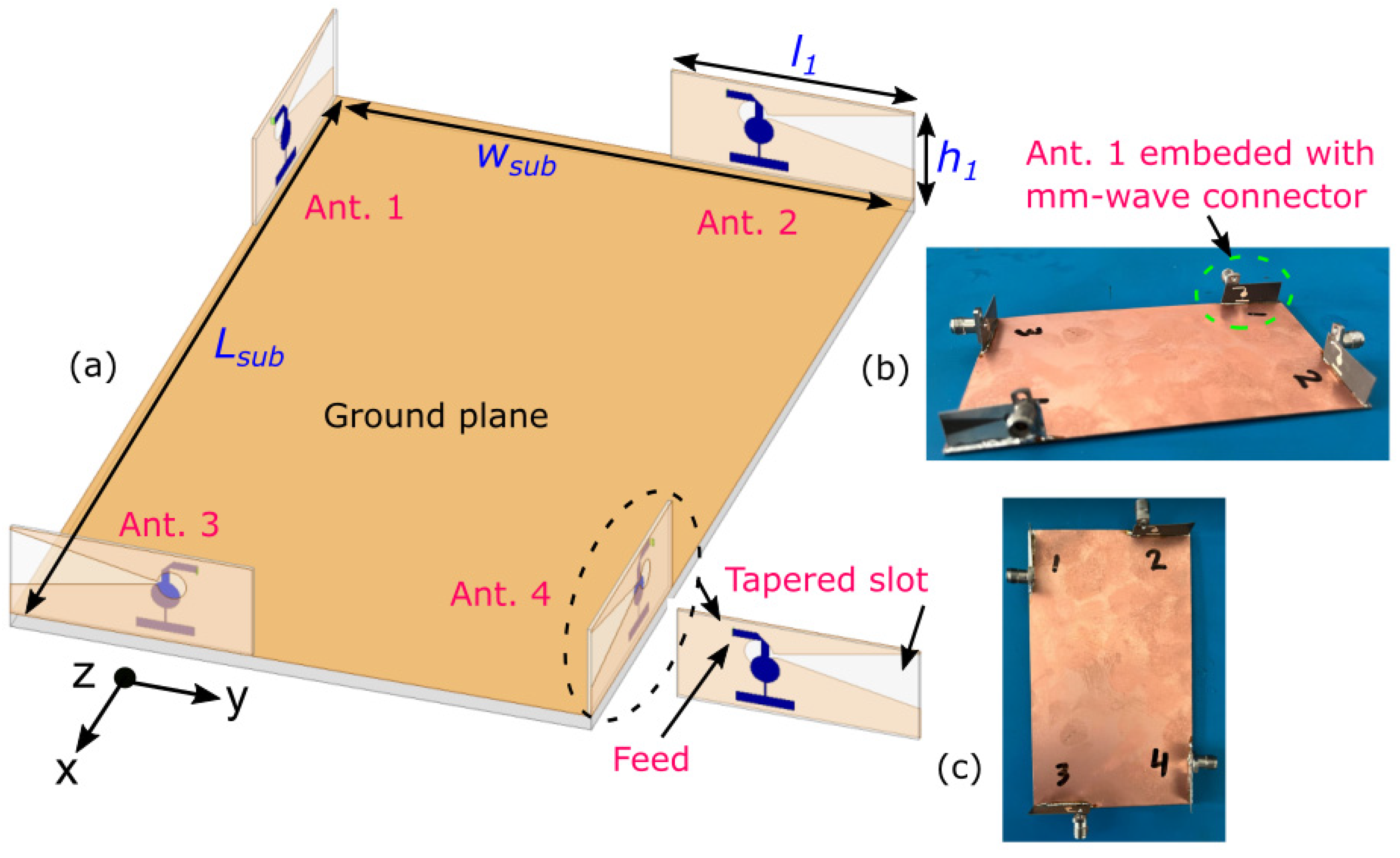
The proposed design is shown in Figure 2, where it has an overall dimension of 120 × 60 × 10 mm3, which is comparable to existing designs [18,19]. The tapered slot and its feeding 50 Ω transmission line are printed on the sidewall of the design using a RO-5880 substrate (length (l1) = 25 × width (h1) = 10 mm2) with a thickness of 0.254 mm, a loss tangent of 0.0009, and relative permittivity (εr) of 2.2. A detailed view of the tapered slot antenna is shown in Figure 2. The radiating antenna part contains a microstrip feedline of 50 Ω and a tapered slot antenna. The tapered slot operates as an open-ended slot antenna at the 3.6 GHz band and, at the same time, as an end-fire Vivaldi antenna at the 28 GHz band, resulting in a shared- aperture and dual-function design. Both the feeding microstrip line and the tapered slot are attached with λ/4 (λ is a free space wavelength at 28 GHz) circular stubs [20]. This circular stub is optimized to improve impedance matching. A low pass filter is also added to the 50 Ω microstrip line to block the high-frequency signal and to work as a stub at low frequency to improve impedance matching. Hence, the low pass filter provides dual functionality. These features of the proposed design make it attractive for installation in mobile phones and other handheld devices in IoT communications.
To achieve a pattern of diversity at both Sub-6 GHz and mm-wave bands, the tapered slot antenna design is integrated along the four sides of the substrate, establishing an MIMO antenna design. The performance of Ant. 1 is depicted in Figure 3. It can be seen from the S-parameters curves that Ant. 1 operates at 3.6 GHz in the 3.5 to 3.8 GHz band as an open slot antenna, and at 28 GHz in the 25 GHz to 29 GHz band as a Vivaldi antenna. These observations can be verified by the 3D radiation patterns shown in Figure 3. Ant. 1 provides a wide beam width at the 3.6 GHz band with a 4 dBi realized gain, and a narrower beam width with a higher realized gain of 8 dBi at 28 GHz. Since Ant. 1 is based on a tapered slot structure, the direction of the radiation is end-fire, as shown in Figure 3. The operating band resonances can be tuned by changing the width and length of the tapered slot. A detailed design procedure with all dimensions is provided [20].
Due to large inter-antenna element spacing and antenna placement orientation, the isolation (coupling) between adjacent antenna elements is low, i.e., more than 17 dB between Ant. 1 and Ant. 2. Moreover, the MIMO design has four directional radiation beams pointing to four different locations (φ = 180°, φ = 0°, φ = −90°, and φ = 90°) in the azimuth plane (the X-Yplane) at both the 3.6 GHz and the 28 GHz bands. This indicates a low correlation coefficient (ρ) value between adjacent antenna radiation beams, i.e., between Ant. 1 & Ant. 2, resulting in a design that is a favorable candidate for MIMO communications [21,22,23]. This design is also justified by the 3D radiation patterns shown in Figure 4. The verified simulation and measurement results are presented in Section 3 to validate the design.
3. Simulation and Measurement Results and Discussions
The proposed MIMO antenna is simulated using a high frequency structured simulator (HFSS). The design was fabricated and tested at the University of Queensland, Australia. A photograph of the fabricated prototype is provided in Figure 2. A DC-40 GHz 2.92 mm connector was assembled, with each antenna feeding via soldering for measurement purposes. Figure 5 shows the measurement setup used in an anechoic chamber for radiation and gain patterns.
The simulated S-parameter curves for Ant. 1, Ant. 2, Ant. 3, and Ant. 4 are shown in Figure 6a, while the measured S-parameter curves for Ant. 1, Ant. 2, Ant. 3, and Ant. 4 are shown in Figure 6b. These results are plotted for the Sub-6 GHz band. It can be seen that the proposed MIMO antenna (S11, S22, S33, and S44) operates at 3.6 GHz. An impedance matching bandwidth of approximately 300 MHz with −10 dB impedance matching is achieved in the simulation and measured versions. A slight shift in measurements is observed, attributable to the fabrication and measurement tolerances. Isolation in both simulated and measured versions is more than 17 dB in the whole operated band. See Figure 6a for S12 (Ant. 1 and Ant. 2), S13 (Ant. 1 and Ant. 3), and S24 (Ant. 1 and Ant. 2).
The simulated and measured S-parameter curves for Ant. 1, Ant. 2, Ant. 3, and Ant. 4 for mm-wave bands are shown in Figure 7a,b. Both the simulated and measured results show good agreement. All the antenna elements (S11, S22, S33, and S44) show −10 dB impedance matching from 25 GHz to 29 GHz. A slight discrepancy in the measured curves, especially for Ant. 3, is attributable to fabrication and measurement tolerances. The isolation in the mm-wave band is more than 30 dB between all antennas (Ant. 1 to Ant. 4).
The normalized simulated and measured 2D radiation patterns, in terms of gain for Ant. 1, Ant. 2, Ant. 3, and Ant. 4 at 3.6 GHz, are shown in Figure 8. The simulated plots follow the measured plot trend, showing good agreement. Each plot has a directional radiational pattern with wider beamwidth, illustrating the MIMO pattern diversity performances.
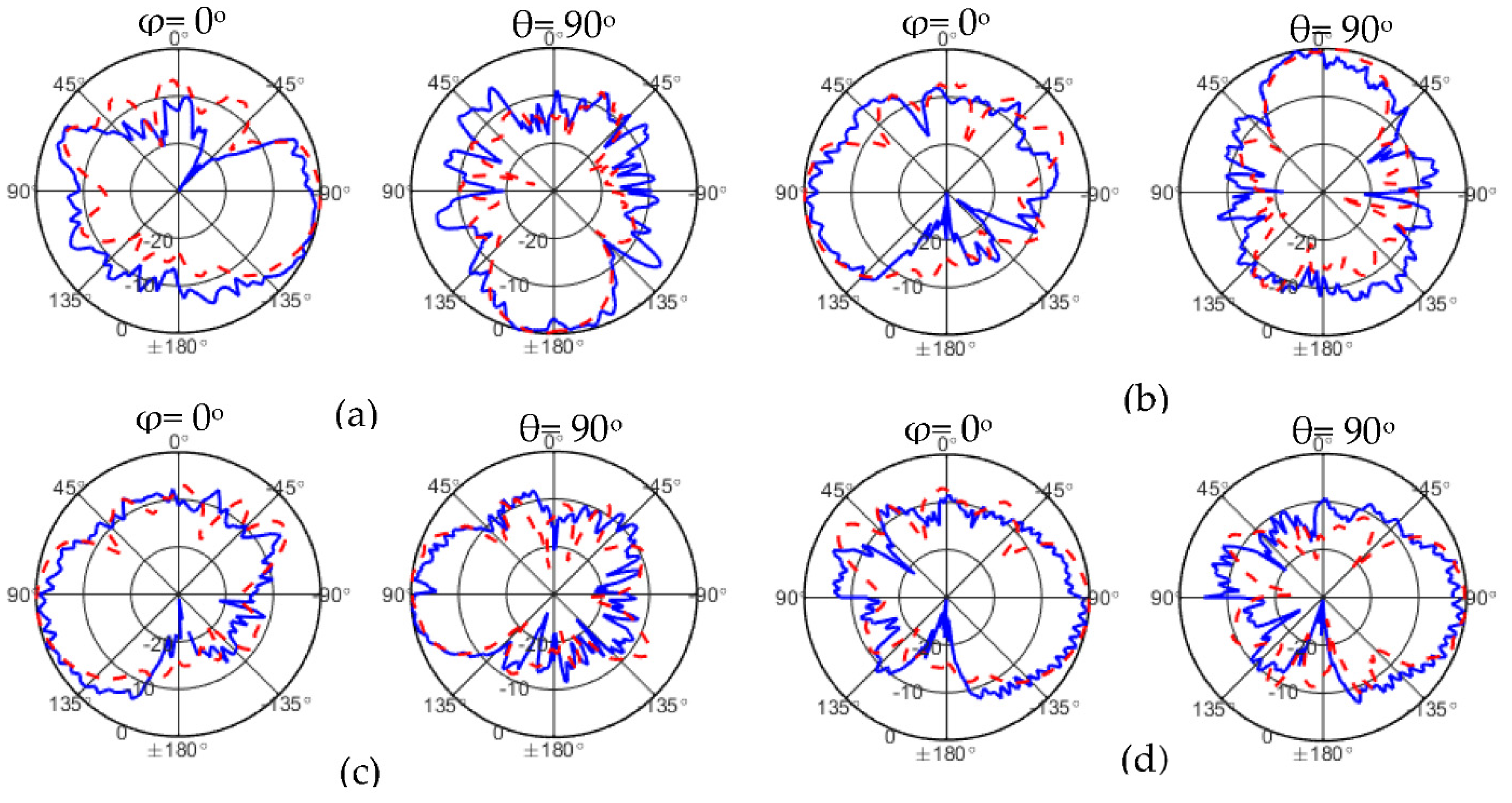
The normalized simulated and measured 2D radiation patterns, in terms of gain for Ant. 1, Ant. 2, Ant. 3, and Ant. 4 at 28 GHz, are shown in Figure 9. The simulated plots follow the measured plot trend, showing good agreement. Each plot has a more directional radiational pattern with a narrow beamwidth, compared to the 3.6 GHz band. This is an advantage, because more directive antennas are needed at the mm-wave band to compensate for higher path loss. The results also indicate that MIMO radiation pattern diversity performances are at the mm-wave band. As shown in Figure 8, at θ = 90° (X-Y plane), the main beam of Ant. 1 is pointing (i.e., the propagating direction of the signal) in the x-direction (φ = 180°); Ant. 2 is pointing in the x-direction (φ = 0°); Ant. 3 is pointing in the-y-direction (φ = −90°); and Ant. 4 is pointing in the y-direction (φ = 90°), covering most of the azimuth plane (X-Y plane) of special coverage.
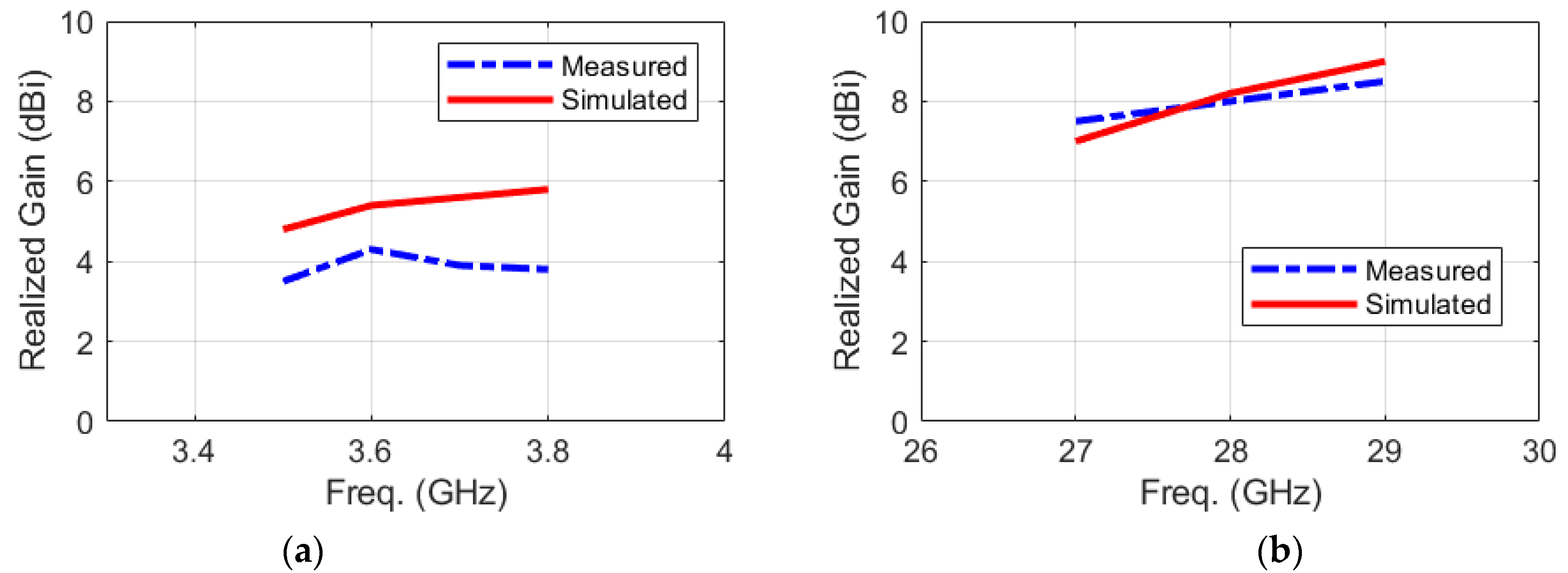
The peak simulated and measured realized gain of each antenna is more than 3.5 dBi in the whole covered band at Sub-6 GHz band, as shown in Figure 10a. While, the peak simulated and measured realized gain of each antenna is more than 8 dBi in the whole covered band at mm-wave, as shown in Figure 10b. Good agreement between simulated and measured realized gain is achieved.
4. Comparison with State-of-the-Art Designs
The proposed MIMO antenna design is compared with the recent state-of-the-art shared aperture MIMO antenna designs in Table 1. The MIMO design [13] only covers the mm-wave band and is not a shared aperture antenna, while other designs [14,16,17] covered both Sub-6 GHz and mm-wave bands. However, [17] does not have MIMO configurations and others have somewhat larger-sized and comparatively complex structures. The proposed design, which operates at Sub-6 GHz and mm-wave bands using a single tapered slot structure and provides MIMO characteristics at both bands, has a compact size and a simple structure.
5. Conclusions
In this work, a multi-band and multi-beam antenna for 5G MIMO Internet of Things (IoT) has been presented. The antenna structure consists of four tapered slots and has been placed on the corner of a smartphone to realize pattern diversity. The tapered slot has dual functionality: It operates as an open-ended slot antenna at band 3.6 GHz with a measured impedance bandwidth of 300 MHz, and as an end-fire tapered slot antenna at 28 GHz, with a measured impedance bandwidth of 4 GHz. The measured realized gains at Sub-6 GHz and mm-wave bands are 3.5 dBi and 8 dBi, respectively. The measured results show that the proposed design fulfills the requirements of multiple wireless communication standards (5G/B5G) at both the Sub-6 GHz and mm-wave bands.
Funding
This research received no external funding.
Institutional Review Board Statement
Not applicable.
Informed Consent Statement
Not applicable.
Data Availability Statement
Not applicable.
Conflicts of Interest
The author declares no conflict of interest.
References
- Andrews, J.G.; Buzzi, S.; Choi, W.; Hanly, S.V.; Lozano, A.; Soong, A.C.; Zhang, J.C. What will 5G be? IEEE J. Sel. Areas Commun. 2014, 32, 1065–1082. [Google Scholar] [CrossRef]
- Asad, S.M.; Ansari, S.; Ozturk, M.; Rais, R.N.B.; Dashtipour, K.; Hussain, S.; Abbasi, H.Q.; Ali Imran, M. Mobility management-based autonomous energy-aware framework using machine learning approach in dense mobile networks. Signals 2020, 1, 170–187. [Google Scholar] [CrossRef]
- Pinto, J.F.; Silva, d.H.S.; Melo, F.; Fred, A. ScientIST: Biomedical Engineering Experiments Supported by Mobile Devices, Cloud and IoT. Signlas 2020, 1, 110–120. [Google Scholar] [CrossRef]
- Basenese, L. 5 Reasons to Let It Ride on 5G. Available online: https://www.smarteranalyst.com/bloggers-corner/resonant-resn-5-reasons-to-let-it-ride-on-5g/ (accessed on 10 December 2021).
- Parchin, N.O.; Al-Yasir, Y.I.A.; Ali, A.H.; Elfergani, I.; Noras, J.M.; Rodriguez, J.; Abd-Alhameed, R.A. Eight-element dual-polarized MIMO slot antenna system for 5G smartphone applications. IEEE Access 2019, 7, 15612–15622. [Google Scholar] [CrossRef]
- Sharawi, M.S.; Ikram, M.; Shamim, A. A two concentric slot loop based connected array MIMO antenna system for 4G/5G terminals. IEEE Trans. Antennas Propag. 2017, 65, 6679–6686. [Google Scholar] [CrossRef] [Green Version]
- Krishna, S. Design and Development of 5G Spectrum Massive MIMO Array Antennas for Base Station and Access Point Applications; Sharma, S.K., Ed.; ProQuest Dissertations Publishing: Ann Arbor, MI, USA, 2018. [Google Scholar]
- Ikram, M.; Sharawi, M.S.; Klionovski, K.; Shamim, A. A switched-beam millimeter-wave array with MIMO configuration for 5G applications. Microw. Opt. Technol. Lett. 2018, 60, 915–920. [Google Scholar] [CrossRef]
- Khalid, M.; Iffat Naqvi, S.; Hussain, N.; Rahman, M.; Mirjavadi, S.S.; Khan, M.J.; Amin, Y. 4-port mIMO antenna with defected ground structure for 5G millimeter wave applications. Eletronics 2020, 9, 71. [Google Scholar] [CrossRef] [Green Version]
- Gui, G.; Liu, M.; Tang, F.; Kato, N.; Adachi, F. 6G: Opening new horizons for integration of comfort, security, and intelligence. IEEE Wirel. Commun. 2020, 27, 126–132. [Google Scholar] [CrossRef]
- Bariah, L.; Mohjazi, L.; Muhaidat, S.; Sofotasios, P.C.; Kurt, G.K.; Yanikomeroglu, H.; Dobre, O.A. A prospective look: Key enabling technologies, applications and open research topics in 6G networks. IEEE Access 2020, 8, 174792–174820. [Google Scholar] [CrossRef]
- Hong, W. Solving the 5G mobile antenna puzzle: Assessing future directions for the 5G mobile antenna paradigm shift. IEEE Microw. Mag. 2017, 18, 86–102. [Google Scholar] [CrossRef]
- Sehrai, D.A.; Abdullah, M.; Altaf, A.; Kiani, S.H.; Muhammad, F.; Tufail, M.; Irfan, M.; Glowacz, A.; Rahman, S. A novel high gain wideband MIMO antenna for 5G millimeter wave applications. Eletronics 2020, 9, 1031. [Google Scholar] [CrossRef]
- Islam, S.; Zada, M.; Yoo, H. Low-pass filter based integrated 5G smartphone antenna for Sub-6-GHz and mm-wave bands. IEEE Trans. Antennas Propag. 2021, 69, 5424–5436. (In English) [Google Scholar] [CrossRef]
- Ikram, M.; Abbas, E.A.; Nguyen-Trong, N.; Sayidmarie, K.H.; Abbosh, A. Integrated frequency-reconfigurable slot antenna and connected slot antenna array for 4G and 5G mobile handsets. IEEE Trans. Antennas Propag. 2019, 67, 7225–7233. [Google Scholar] [CrossRef]
- Ikram, M.; Nguyen-Trong, N.; Abbosh, A. Hybrid antenna using open-ended slot for integrated 4G/5G mobile application. IEEE Antennas Wirel. Propag. Lett. 2020, 19, 710–714. [Google Scholar] [CrossRef]
- Bae, J.H.; Yoon, Y.J. 5G dual (S-/Ka-) band antenna using thick patch containing slotted cavity array. IEEE Antennas Wirel. Propag. Lett. 2021, 20, 1008–1012. (In English) [Google Scholar] [CrossRef]
- Wong, K.-L.; Tsai, C.-Y. Half-Loop frame antenna for the LTE metal-casing tablet device. IEEE Trans. Antennas Propag. 2017, 65, 71–81. [Google Scholar] [CrossRef]
- Rodriguez-Cano, R.; Zhang, S.; Zhao, K.; Pedersen, G.F. Reduction of main beam-blockage in an integrated 5G array with a metal-frame antenna. IEEE Trans. Antennas Propag. 2019, 67, 3161–3170. [Google Scholar] [CrossRef] [Green Version]
- Ikram, M. Multi-Functional Antenna Structures for 4G/5G Wireless Communication Devices. Ph.D. Thesis, The University of Queensland, St. Lucia, Australia, 2021. [Google Scholar]
- Sharawi, M.S. Printed multi-band MIMO antenna systems and their performance metrics [Wireless corner]. IEEE Antennas Propag. Mag. 2013, 55, 218–232. [Google Scholar] [CrossRef]
- Qureshi, U.; Khan, M.U.; Sharawi, M.S.; Burokur, S.N.; Mittra, R. Field decorrelation and isolation improvement in an MIMO antenna using an all-dielectric device based on transformation electromagnetics. Sensors 2021, 21, 7577. [Google Scholar] [CrossRef] [PubMed]
- Ikram, M.; Nguyen-Trong, N.; Abbosh, A. Multiband MIMO microwave and millimeter antenna system employing dual-function tapered slot structure. IEEE Trans. Antennas Propag. 2019, 67, 5705–5710. [Google Scholar] [CrossRef]
Figure 1.
Integrated Sub-6 GHz and mm-wave bands IOT-based communication system and potential utilization of the proposed MIMO antenna design.
Figure 1.
Integrated Sub-6 GHz and mm-wave bands IOT-based communication system and potential utilization of the proposed MIMO antenna design.
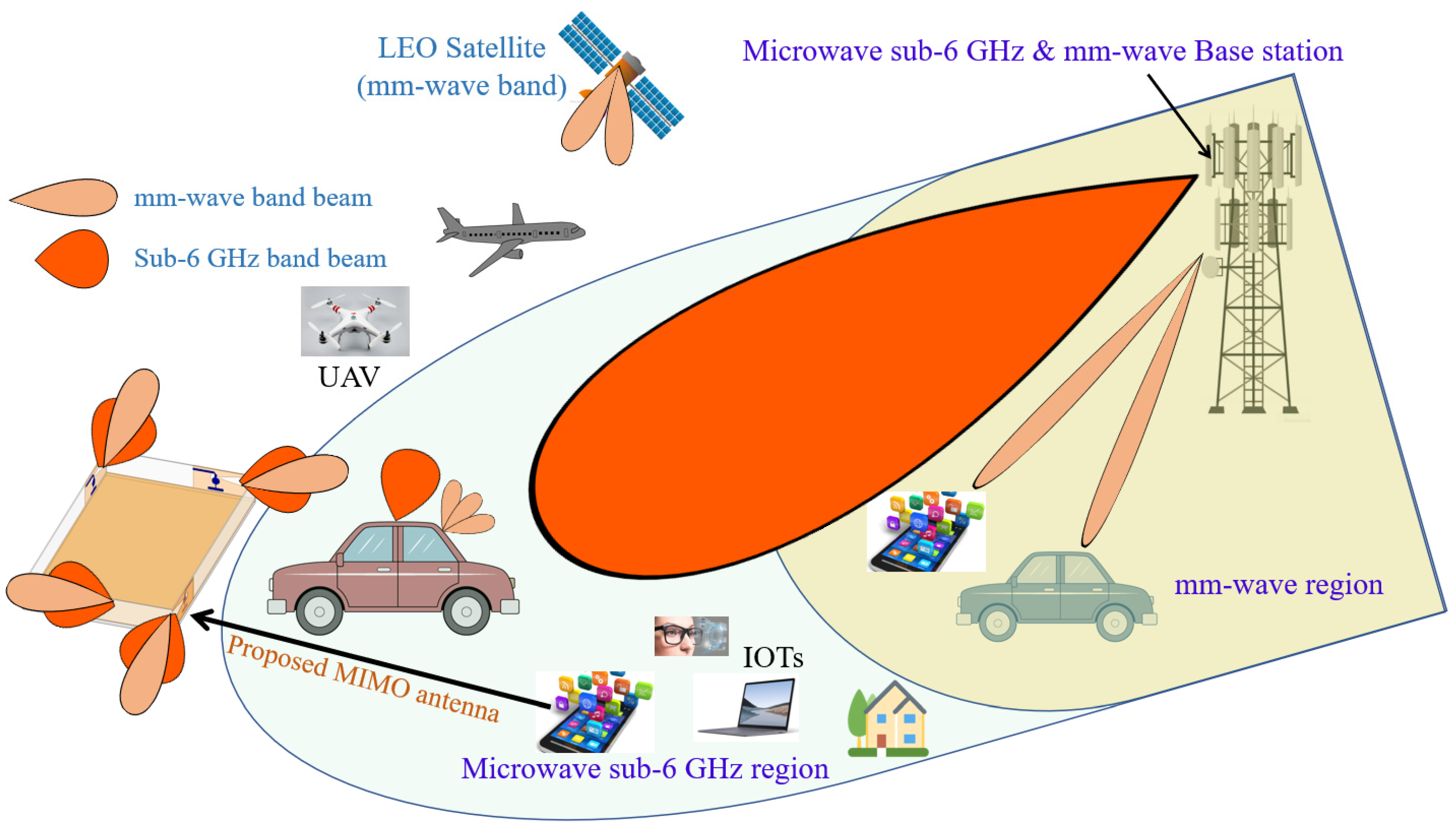
Figure 2.
The proposed MIMO antenna design: (a) full configuration; (b,c) fabricated prototype.

Figure 3.
The performance of the proposed MIMO antenna design when only Ant. 1 is excited (operating).
Figure 3.
The performance of the proposed MIMO antenna design when only Ant. 1 is excited (operating).
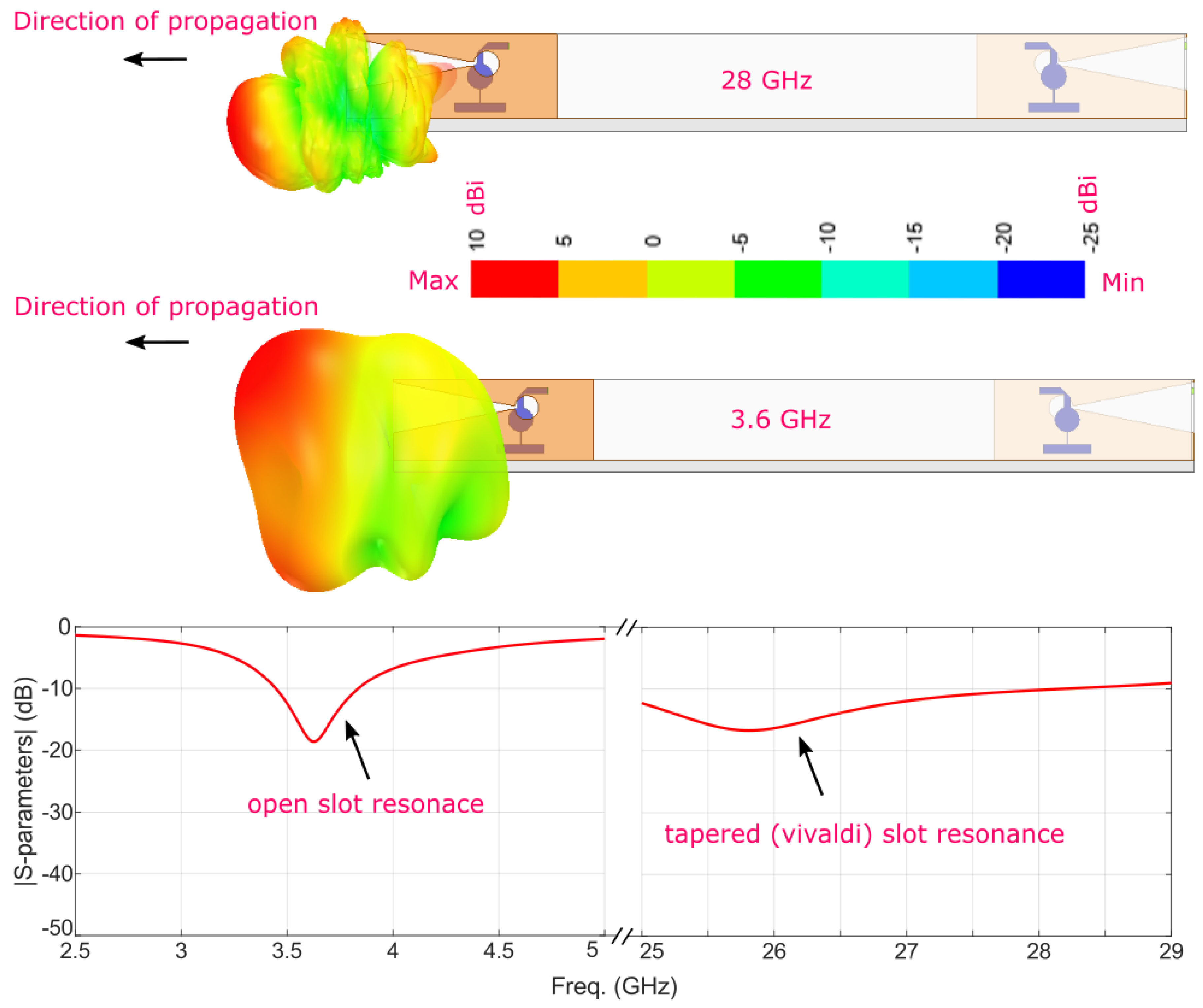
Figure 4.
The 3D radiation patterns of the proposed MIMO antenna at (a) 28 GHz and (b) 3.6 GHz.
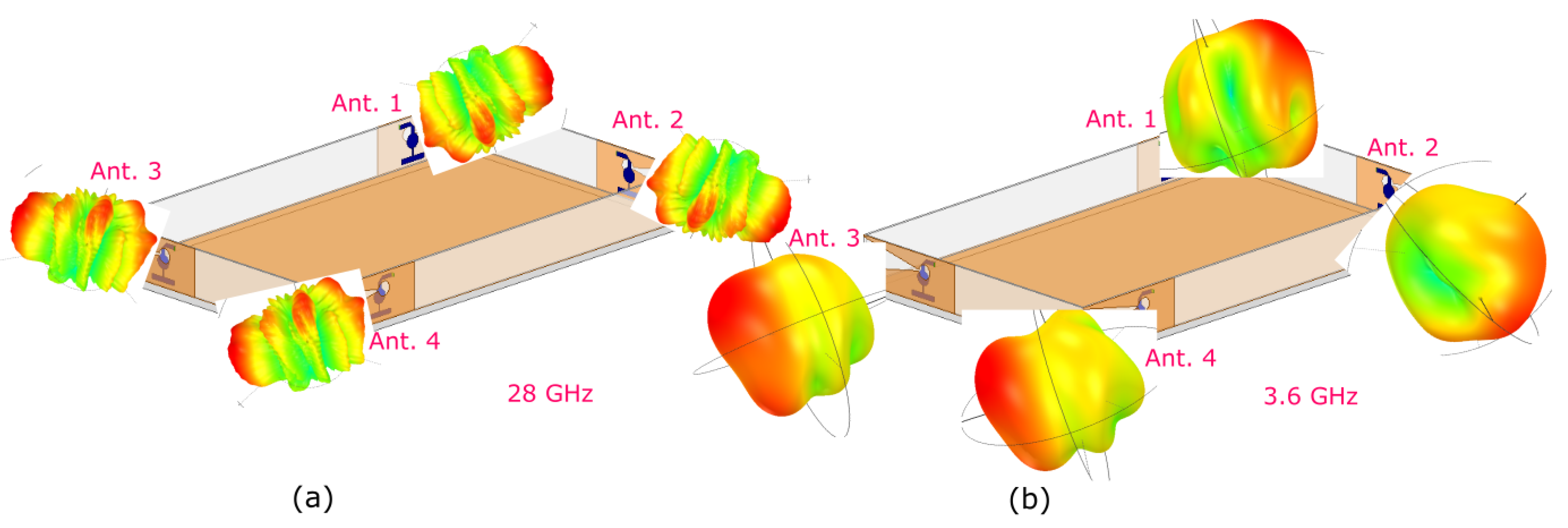
Figure 5.
The proposed MIMO antenna design installed inside an anechoic chamber in the antenna measurement lab.
Figure 5.
The proposed MIMO antenna design installed inside an anechoic chamber in the antenna measurement lab.

Figure 6.
S-parameter curves for Ant. 1 to Ant. 4 at 5G Sub-6 GHz band: (a) simulated and (b) measured.
Figure 6.
S-parameter curves for Ant. 1 to Ant. 4 at 5G Sub-6 GHz band: (a) simulated and (b) measured.

Figure 7.
S-parameter curves for Ant. 1 to Ant. 4 at 5G mm-wave band: (a) simulated and (b) measured.
Figure 7.
S-parameter curves for Ant. 1 to Ant. 4 at 5G mm-wave band: (a) simulated and (b) measured.
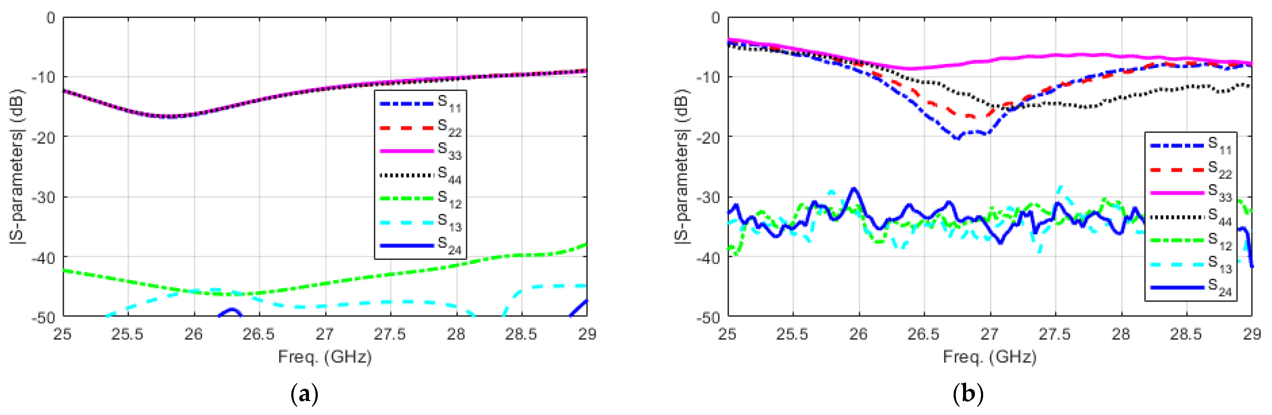
Figure 8.
The simulated and measured 2D radiation patterns in terms of gain at 3.6 GHz: (a) Ant. 1, (b) Ant. 4, (c) Ant. 2, and (d) Ant. 3. Simulated: dashed red curves; measured: solid blue curves.
Figure 8.
The simulated and measured 2D radiation patterns in terms of gain at 3.6 GHz: (a) Ant. 1, (b) Ant. 4, (c) Ant. 2, and (d) Ant. 3. Simulated: dashed red curves; measured: solid blue curves.

Figure 9.
The simulated and measured 2D radiation patterns in terms of gain at 28 GHz: (a) Ant. 1, (b) Ant. 4, (c) Ant. 2, and (d) Ant. 3. Simulated: dashed red curves; measured: solid blue curves.
Figure 9.
The simulated and measured 2D radiation patterns in terms of gain at 28 GHz: (a) Ant. 1, (b) Ant. 4, (c) Ant. 2, and (d) Ant. 3. Simulated: dashed red curves; measured: solid blue curves.

Figure 10.
The simulated and measured realized gain at (a) Sub-6 GHz and (b) mm-wave bands.


Table 1.
Comparison of the proposed MIMO antenna design with state-of-the-art designs.
| References | Overall Size (mm3) | Sub-6 GHz Bands | mm-Wave Bands | MIMO Configurations | Realized Gain @ 28 GHz |
|---|---|---|---|---|---|
| [13] | 80 × 80 × 1.57 | Not covered | 28, 38 | 4-element at mm-wave | 10 |
| [14] | 157.7 × 70 × 0.51 | 3.5 | 28, 38 | 8-element at Sub-6 GHz 8-element at mm-wave | 8 |
| [16] | 150 × 75 × 0.51 | 0.8, 2 | 28 | 2-element at Sub-6 GHz 4-element at mm-wave | 11 |
| [17] | 22.8 × 22.8 × 3.4 | 3.5 | 28 | No | 12 |
| This Work | 100 × 60 × 10 | 3.6 | 28 | 4-element at Sub-6 GHz 4-element at mm-wave | 8 |
Publisher’s Note: MDPI stays neutral with regard to jurisdictional claims in published maps and institutional affiliations. |
© 2022 by the author. Licensee MDPI, Basel, Switzerland. This article is an open access article distributed under the terms and conditions of the Creative Commons Attribution (CC BY) license (https://creativecommons.org/licenses/by/4.0/).
Share and Cite
MDPI and ACS Style
Ikram, M. 5G/B5G Internet of Things MIMO Antenna Design. Signals 2022, 3, 29-37. https://doi.org/10.3390/signals3010003
AMA Style
Ikram M. 5G/B5G Internet of Things MIMO Antenna Design. Signals. 2022; 3(1):29-37. https://doi.org/10.3390/signals3010003
Chicago/Turabian StyleIkram, Muhammad. 2022. "5G/B5G Internet of Things MIMO Antenna Design" Signals 3, no. 1: 29-37. https://doi.org/10.3390/signals3010003