Abstract
A new approach to accelerating the evaluation of monopole and dipole source integrals via the fast multipole method (FMM) in the time domain for general three-dimensional (3-D) aeroacoustic problems is presented in this paper. In this approach, the aeroacoustic field is predicted via a hybrid method that uses computational fluid dynamics (CFD) for near-field flow field calculations and the Ffowcs Williams–Hawkings (FW-H) acoustic analogy for far-field sound field predictions. The evaluation of the surface integrals of the monopole and dipole source terms appearing in the FW-H formulation is accelerated by a 3-D FMM to reduce computational cost. The proposed method is referred to as Fast FW-H in this work. The performance and efficiency of the proposed methodology are demonstrated using several examples. First, aeroacoustic predictions for the cases of a stationary acoustic monopole, moving acoustic monopole and stationary acoustic dipole in a uniform flow are studied, generally showing good agreement with the analytical solutions. Second, the sound field radiating from a flow passing a finite-length circular cylinder and the propeller of an unmanned aerial vehicle (UAV) during forward flight are studied, and the computed results obtained via the FW-H and Fast FW-H methods in the time domain with a stationary, permeable surface are compared. The overall computational efficiency of the sound field solutions obtained via the Fast FW-H method is found to be approximately two times faster than the computational efficiency of the original FW-H method, indicating that this proposed approach can be an accurate and efficient computational tool for modelling far-field aeroacoustic problems.
1. Introduction
The development of aeroacoustic noise prediction tools for analysing the aeroacoustic characteristics of a source, a propagation path and the region of a far-field sound receiver is of great interest. The demand for a low level of aeroacoustic noise in the initial design of aircraft, propellers, high-speed trains, cars and fans should be considered since noise regulations have become more stringent []. Therefore, more robust, accurate and efficient computational aeroacoustic methods are needed to achieve the desired noise reduction without causing a significant loss of performance. The far-field sound receiver region is often of interest in evaluating the impact of environmental noise. With the increasing power of computers, using numerical methods to investigate the sound field is becoming a popular approach. Compared with the use of a direct calculation method for an aeroacoustic prediction, a hybrid calculation method uses less storage space and less calculation time []. Consequently, hybrid aeroacoustic calculation methods are currently widely used; namely, the computational fluid dynamics (CFD) approach is applied to capture the sound generation and propagation of a fluid flow in the near field, while in the far field, the acoustic analogy theory is adopted to compute the sound field distribution. Additionally, as calculation models become increasingly complex, larger storage spaces are required for hybrid calculation methods, resulting in longer calculation times despite the rapidly increasing capacity of computers. Therefore, solving the storage space difficulty with using computational aeroacoustic models and improving computing efficiency are also urgent problems that need to be addressed.
The sound generated by a fluid flow can be described using the basic equations of fluid mechanics, namely, the Navier–Stokes equations. In 1952, Lighthill [] rearranged the flow continuity and momentum equations and took the fluctuating density as an independent variable to obtain an acoustic analogy; this marked the birth of aeroacoustics. Under conditions in which the source terms can be obtained independently, such as via CFD methods, Lighthill’s acoustic analogy can describe the sound generated by an unsteady flow in an unbounded domain. Subsequently, to eliminate the influence of rigid boundaries on aeroacoustics, Curle [] extended Lighthill’s acoustic analogy to Curle’s equation in 1955 by using Kirchhoff’s method, which acts as dipole source terms contributed by the loads of a rigid boundary surface. Considering the influence of arbitrary moving boundaries on aeroacoustics, Ffowcs Williams and Hawkings [] further extended Curle’s equation in 1969 by using the generalised function method to obtain the well-known Ffowcs Williams–Hawkings (FW-H) acoustic analogy equation. The FW-H equation is an inhomogeneous wave equation, and the right-hand side of the FW-H equation includes the original noise terms, comprising monopole, dipole and quadrupole terms.
Since the FW-H equation was proposed, most of the research studies in engineering applications have focused on means of calculating the sound generated by various sound sources through an acoustic analogy method. However, in many cases, calculating a quadrupole sound source in relation to fluid nonlinearity is difficult. Therefore, some researchers have attempted to find new ways to calculate the total aerodynamic noise, including nonlinear fluid effects. In 1979, Hawkings [] established an aeroacoustic model of a high-speed open rotor by using Kirchhoff’s integral formulation and obtained satisfactory results to solve the generation of sound in non-uniform flow. In 1988, Farassat and Myers [] extended Kirchhoff’s formulation to a more general case that could be used to calculate the sound field generated by any moving flow medium. However, the application of the FW-H method was greatly limited due to its requirement of fluid impenetrability on the integral surface []. In 1997, Brentner et al. [,] focused on the quadrupole source terms in the FW-H equation and converted the volume component of the quadrupole source terms into a surface integral form, thereby forming a formulation Q1A method for solving the quadrupole source contribution. In 1997, Di Francescantonio [] combined Kirchhoff’s integral formulation and the FW-H equation to deduce the K-FWH formulation, which breaks the impenetrability limit of the integral surface. This development enabled the FW-H equation to be widely applied in the numerical prediction of aeroacoustic problems.
At present, the retarded time method [,] is mainly used to solve actual aeroacoustic problems. This method requires a numerical solution for the retarded time terms, which form a transcendental equation. In addition, the retarded time method needs to store a large amount of aerodynamic data for a period of time and to conduct numerical interpolation, so this method is very inefficient for solving large-scale problems, such as those with a large number of cells on the integral surface and a large number of receiver points. Therefore, to improve the calculation efficiency, for the FW-H equation derived by Farassat [], the retarded time terms of the Farassat 1 and Farassat 1A equations were solved in 2003 by Casalino [], who proposed an advanced time approach for FW-H acoustic analogy predictions. This approach further improved the aeroacoustic calculation efficiency.
The above-mentioned solution method for solving the FW-H equation is in the time domain, referred to as the “time-domain method”. The topic of helicopter noise and open rotor noise has been studied extensively using such methods []. To avoid the Doppler singularity when the source velocity is supersonic and to improve the computational efficiency in the time-domain method, Gennaretti et al. [] adopted a frequency response function to predict the tonal noise emitted by rotors in arbitrary steady motion and derived a frequency domain method of predicting the monopole and dipole terms of the harmonic noise generated by the open rotors, hereinafter referred to as the “frequency-domain method”. Tang et al. [] used the free-space frequency-domain Green’s function to obtain a frequency-domain solution for the FW-H equation which can solve the monopole, dipole and quadrupole terms of the FW-H equation for problems involving radiation from a penetrating sound source. In addition, the frequency-domain method can avoid the retarded time terms and avoid the interpolation in the time-domain method due to the integral calculation on the surface of the sound source, further improving the solution efficiency [,,,,]. Some other recent contributions in the research on computational aeroacoustics using FW-H integrals, CFD, boundary elements, finite volume methods and/or experimental validations can be found in Refs. [,,,,,].
With the increases in the sizes of the models used in the analysis of aeroacoustic problems, such as the increase in the length scale of the sound field and the increase in the number of sound receiver points, the above-mentioned traditional numerical methods (either the time-domain method or frequency-domain method) have difficulty meeting the requirements of large-scale numerical simulations with respect to calculation time, storage capacity and lower computational costs. Therefore, studies of other methods, such as the fast multipole method (FMM), to accelerate aeroacoustic calculation, reduce the prediction time and improve the calculation accuracy are urgently needed for solving large-scale aeroacoustic models. The boundary element method (BEM) has attracted the attention of researchers in recent years.
The FMM was first proposed by Greengard and Rokhlin [,] to accelerate the Laplace equation solutions, promising to reduce the computation cost in a FMM-accelerated BEM from O(N2) to O(N) (with N being the number of unknowns). The key idea behind the FMM is a multipole expansion of the kernel function in which the connection between the receiver point and the source point is separated. Many research works have been published since then to improve and extend the applicability of the FMM []. The FMM was later extended to the solutions of the traditional acoustic Helmholtz equation [,,,]. A comprehensive review on the FMM was provided by Nishimura [] and Liu [,,]. Subsequently, the FMM was also applied to the study of fast aeroacoustic algorithms in the frequency domain. Cheng et al. [] used a three-dimensional (3-D) broadband adaptive FMM to calculate high-frequency cases and used the partial wave expansion formulation of rotating coaxial translation to calculate low-frequency cases, and this approach effectively accelerated the sound field calculation in the wide frequency domain. Wolf et al. [,] adopted a hybrid calculation method in which the near-field aerodynamic information was obtained via CFD and the far-field sound field was calculated using the accelerated FW-H equation. The results showed that the sound field solution obtained via the accelerated FW-H equation is more efficient than the solution obtained via the conventional FW-H equation. Wolf et al. [] numerically predicted the convective effect of quadrupole noise caused by the airflow of an NACA0012 aerofoil. The results showed that the aerofoil’s convective effects appeared for all frequencies, and the quadrupole source had a more pronounced effect for medium and high frequencies at a higher Mach number. Mao and Xu [] used the spherical harmonic series expansion method to accelerate the solution of the FW-H equation and numerically verified the correctness of the numerical acceleration method for aerodynamic noise. However, this method is only suitable for evaluating far-field aerodynamic noise and cannot be used to predict near-field noise.
In general, the FW-H accelerated by the FMM in the frequency domain is advantageous when the discrete frequency or the tonal noise phenomena are of great interest. However, with the frequency numbers increasing, the frequency-domain method causes the sound field computation to be more time-consuming than when the time-domain method is used. A more efficient method for solving large-scale aeroacoustic problems with multiple receiver points in the far field must be proposed. To the best knowledge of the authors, the computation of aeroacoustic integrals accelerated by the FMM has been limited to the frequency domain, and there are no studies in the literature regarding the related research on accelerating the aeroacoustic integral formulation in the time domain.
In this work, a time-domain numerical method accelerated by the FMM (termed the Fast FW-H method) is proposed for calculations of 3-D aeroacoustic problems. The sound field is predicted via a hybrid method that uses the CFD for the near-field flow field calculation and the FW-H formulation accelerated by the FMM to predict the far-field sound field to reduce the computational cost. The performance and efficiency of the proposed approach are demonstrated using several benchmark examples, including a comparison of the results with experimental data.
The rest of this paper is organised as follows. In Section 2, an improved delayed, detached eddy simulation (IDDES) turbulence model and the monopole source and dipole source terms of the FW-H acoustic analogy are reviewed, and an FW-H formulation in the time domain, accelerated by an FMM (referred to as Fast FW-H), is proposed. In Section 3, sound predictions made using the proposed method are demonstrated, and the results are compared with analytical solutions. In Section 4 and Section 5, applications of the method to the generation of aerodynamic noise via vortex shedding from a finite-length circular cylinder and the propeller of an unmanned aerial vehicle (UAV) during forward flight are demonstrated, validations are provided using experimental results, and comparisons of the computational efficiencies between the conventional FW-H and Fast FW-H methods are demonstrated. In Section 6, a summary is provided to conclude the paper.
2. Formulations
2.1. IDDES Model
Combining the Reynolds-averaged Navier–Stokes (RANS) equations and the large eddy simulation (LES), the detached eddy simulation (DES) [] uses the RANS equations to approximate the behaviour of the mean boundary layer and adopts the LES to more accurately obtain time-dependent flow structures far from geometric surfaces. This combination can effectively reduce the cost of high-Reynolds-number simulations using the LES and guarantee the accuracy of the results. Furthermore, the IDDES turbulence model is a hybrid RANS-LES model consisting of a combination of various new and existing techniques that provides a more flexible and convenient scale-resolving simulation model for high-Reynolds-number flows []. In this paper, an IDDES turbulence model based on Menter’s shear stress transport (SST) two-equation eddy-viscosity turbulence model [] was solved using a finite volume method, and this model was employed to simulate the aerodynamic performance.
2.2. FW-H Acoustic Analogy
We begin with the acoustic analogy formulation developed by Ffowcs Williams and Hawkings. Then, the FW-H equation can be written as the following inhomogeneous wave equation []:
with
where and represent the surface source distributions of mass and linear momentum, respectively []; is the Lighthill stress tensor; is the Dirac delta function; is the speed of sound; is the time; is the space in the () direction; is the Heaviside function; is the sound pressure; is the static fluid pressure in the quiescent medium; is the mean fluid pressure; is the static fluid density; is the initial fluid density in the quiescent medium; is the normal flow velocity; is the normal integral surface velocity in the moving medium; represents the components of the flow velocity; represents the components of the integral surface velocity in the moving medium; represents the components of the unit external normal vector on the integral surface; is the Kronecker delta symbol; is the viscous stress tensor; and is an implicit function that describes the boundary integral surface, as shown in Figure 1. Additionally, in the interior region, and in the outside region, and the implicit function satisfies [] in which denotes the unit normal vector that points towards the outside of the integral surface.
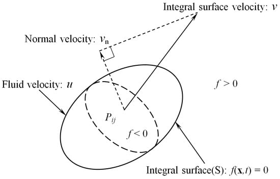
Figure 1.
Boundary integral surface.
The right-hand side of Equation (1) represents the thickness (monopole), loading (dipole) and quadrupole sound source terms. For a flow with a low Mach number, the sound contribution from the quadrupole source becomes small. In this case, the quadrupole source can be neglected [].
Green’s time-domain function in the unbounded 3-D space [] is used to solve Equation (1), and the integral solution of Equation (1) is thus given by []
where is the expression of the sound pressure of the thickness (monopole) source terms, and is the sound pressure of the loading (dipole) source terms.
Finally, the monopole source terms of the FW-H equation (MSFW-H) are obtained as follows []:
where the dots above the quantities denote the time derivative with respect to the source time ; it takes a certain time for the sound from the source location to reach the location of the sound receiver, and this time difference is expressed in terms of the retarded time, denoted as , which means that the time-dependent variable inside the brackets is evaluated at the retarded time ; and are the locations of the receiver points and the integral surface, respectively; and are the point time of the receiver and the retarded time of the integral surface, respectively; and represents the distance between the location of the source’s integral surface and the receiver point; represents the components of the source’s Mach number vector in the direction of the observer; represents the components of the Mach number in the direction; and is a unit vector from a sound source point to a receiver point.
The dipole source terms of the FW-H equation (DSFW-H) are also obtained as follows []:
A flowchart of the FW-H aeroacoustic solution method is given in Figure 2. All the sound field calculations are solved using a Fortran code. The flowchart of the FW-H code shows the main tasks of the program. The program begins by reading the CFD data to identify the nodes and cells of the integral surface and cells and the CFD parameters applied in the FW-H method, such as the fluid pressure and the velocity in the nodes of the cells. For a specific microphone (receiver point) location, the MSFW-H and DSFW-H method can be used to calculate the values of the integrand, such as the cell coordinate information, cell direction vector, and the distance between the cell centre and the microphone. Note that the above solutions are performed within the retarded time . Finally, the time history of the sound pressure for a specific microphone position can be obtained.
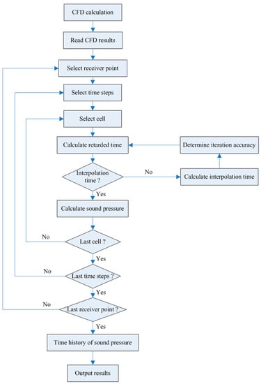
Figure 2.
Flowchart of the FW-H code.
2.3. Fast Multipole Method
In the CFD calculation process, regardless of the sound sources (translation or rotation), any moving object can be dealt with similarly to the model case of a wind tunnel [], as shown in Figure 3. Therefore, a permeable surface is used to enclose the sound source to obtain the flow field information (fluid pressure, fluid velocity, etc.), the aeroacoustic integral equation is further calculated for the permeable integral surface, and the sound pressure of the sound receiver points can be obtained. Research shows that a reasonable permeable integral surface can ensure calculation accuracy [,].
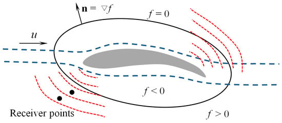
Figure 3.
Schematic of the permeable integral surface.
Therefore, the stationary permeable surface that surrounds the sound source is chosen as the integral surface of the FW-H. In this paper, the permeable surface remains at rest in the fluid domain; therefore, , , . In practice, it is common to neglect the viscous stress tensor for high-Reynolds-number flows, giving simply . Subsequently, the MSFW-H and DSFW-H formulations can be simplified as
An FMM is employed to solve the FW-H formulation (8) and (9). The MSFW-H and DSFW-H formulations in the time domain accelerated by the FMM are referred to as the Fast MSFW-H method and Fast DSFW-H method, respectively. Several expansions and translations are needed in the FMM, and most formulations for potential problems are well documented in Refs. [,,].
2.3.1. Fast MSFW-H Method
The fundamental solution for 3-D potential problems can be expanded with a series expansion as follows [,,,,]:
where is the expansion centre close to the node of the cell in the integral surface, is the complex conjugate, and is the number of expansion terms (set at 15 in this study). The two functions and are called solid harmonic functions [].
Using the static kernel and the integrand function (Equation (8)) related to the integral surface of the sound source, which is only concerned with the flow field information on the permeable integral surface. Therefore, the MSFW-H equation can also be expanded as follows:
By applying the expansion in Equation (10), one can evaluate the integrals in Equation (11) in a representation of the conventional boundary integral equation (CBIE) for as follows:
where represents the multipole moments centred at .
The moment-to-moment (M2M), moment-to-local (M2L) and local-to-local (L2L) translations are present for the kernel integral with the moment [].
2.3.2. Fast DSFW-H Method
First, the kernel is used to accelerate the first terms of the right-hand side of the DSFW-H formulation (given by Equation (9)). The integrand function related to the integral surface of the sound source is also called the function and is only concerned with information about the flow field on the integral surface.
Next, the kernel of the fundamental solution for a three-dimensional potential problem [] is used to accelerate the second terms of the right-hand side of the DSFW-H equation (as shown in Equation (9)). The normal derivative of the kernel with respect to the normal direction of the integral surface can be obtained as follows []:
The second terms of the right-hand side of the DSFW-H equation in Equation (9) related to the integral surface are referred to as the function in this work; this function is only concerned with information about the flow field on the integral surface. Therefore, the right-hand side of the DSFW-H (Equation (9)) can also be expanded as follows:
By applying the expansion in Equations (10) and (13), one can evaluate the integrals in Equation (14) in a CBIE for as follows:
where is the multipole moment centred at .
The same M2M, M2L and L2L translations are also valid for the kernel integral with the moment [].
The details of the implementations of the FMM and the various parameters used in the FMM can be found in Ref. []. All the sound field calculations are solved using a Fortran code. The program begins by reading the CFD data to identify the nodes and cells of the integral surface and the CFD parameters applied in the FW-H method, such as the fluid pressure and the velocity in the nodes of the cells. All computations are performed on a desktop workstation with an Intel Xeon Gold 6132 processor working at 2.6 GHz with 128 GB of memory.
3. Numerical Examples and Verification
In this study, the software package ANSYS Fluent 19.2 is used to carry out the flow field calculations. The aeroacoustic numerical simulation is solved via the conventional FW-H and Fast FW-H method codes. The scenarios of a stationary acoustic monopole and a moving acoustic monopole in a uniform flow medium are employed to verify the MSFW-H and Fast MSFW-H methods. Next, a stationary point dipole source in a moving medium is studied numerically to verify the accuracy of the DSFW-H and Fast DSFW-H methods.
3.1. Test Case 1: A Stationary Acoustic Monopole in a Uniform Flow
As the first problem, a stationary acoustic monopole in a uniform background flow is used to verify the MSFW-H (Equation (8)) and Fast MSFW-H (Equation (12)) methods. Lockard [] provided a harmonic velocity potential function from the sound field generated by a stationary acoustic monopole in a uniform flow as follows:
where is the single frequency of the sound source; is the velocity potential amplitude, in all cases; and the ambient speed of sound is set to 340 m/s.
The other variables are defined as
where denotes the initial Mach number. When the sound source moves in the −x1 direction at a uniform flow velocity , an equivalent flow involves a fixed source at the origin in a uniform flow in the +x1 direction at a flow velocity . Additionally, the induced particle velocity is obtained from
Therefore, the sound pressure of the monopole source terms can be expanded as follows:
where is the density of the acoustic medium. The initial flow density is equal to 1.225 kg/m3 in this paper.
Maintaining a focus on the numerical implementation and verification, to avoid any bias relating to the numerical accuracy caused by the CFD calculation, the flow properties of the sound source’s surface are obtained from the exact solution of the flow field generated by the stationary acoustic monopole, i.e., Equations (16)–(19). A closed spherical, permeable surface with a radius is used as the flow data surface. Note that closed spherical, permeable surfaces with different radii, e.g., , are also verified, and the numerical results match well with the analytical solution (the sound pressure in Equation (20) is referred to as the analytical solution). The theoretical analysis results are then used as the flow field input to the MSFW-H and Fast MSFW-H code for this problem.
The monopole point source is placed at the origin of the coordinate system, and a nondimensional variable R (also called the reference length) is adopted. The receiver points are located at a geometrical centre of 340R (far field) or 5R (near field) from the acoustic monopole source. In this work, the frequency bandwidth is set to 5 Hz, and two Mach numbers, and , are verified. In addition, the aeroacoustic Formulation 1C prediction model proposed by Najafi-Yazdi et al. [] is also verified. Figure 4 shows a comparison of the root mean square (RMS) values of the sound pressure generated by a stationary acoustic monopole in a uniform flow with receiver points located at . The sound directivity pattern is biased towards the upstream position, and the amplitude of the sound pressure is larger than the amplitude of the sound pressure downstream due to the convection effect []; the same conclusion was also reached by Ghorbaniasl et al. []. With an increase in the mean flow or Mach number, the difference in the amplitude of the sound pressure becomes more obvious. Compared with the analytical solution, the errors generated by the MSFW-H and Fast MSFW-H codes are less than 0.25%. The MSFW-H and Fast MSFW-H methods are adequate for numerically accurate far-field predictions, as shown in Figure 4.
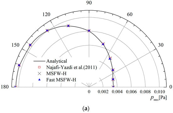
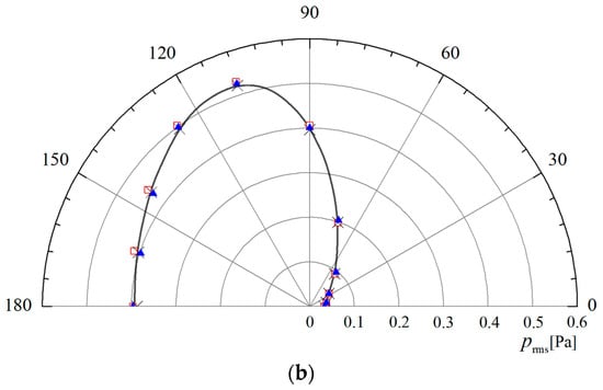
Figure 4.
Comparison of the RMS values of the sound pressure of an acoustic monopole, obtained via the MSFW-H method and Fast MSFW-H method at in the far field: (a) ; (b) [].
Figure 5 shows a comparison of the RMS values of the sound pressure generated by an acoustic monopole in a uniform flow in the near field with receiver points located at . Excellent agreement is obtained between the sound pressure amplitudes and the sound directivity patterns compared with the analytical solution results. Compared with the analytical solutions, the errors generated by the MSFW-H and Fast MSFW-H formulations are less than 0.4%. The main reason for the small deviation between the results of the numerical simulation algorithms and the analytical solution is that the numerical predictions were made very close to the permeable integral surface; as a result, the mesh cells were no longer acoustically compact [].
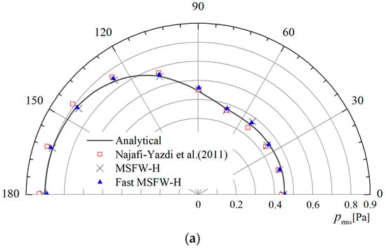
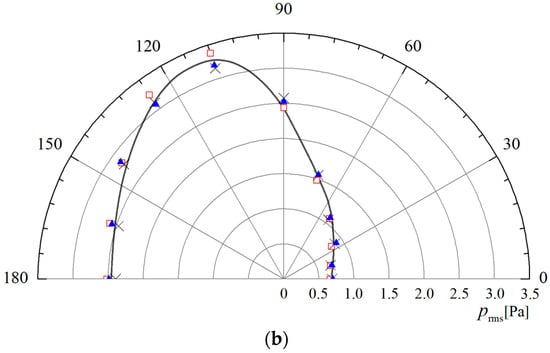
Figure 5.
Comparison of the RMS values of the sound pressure of an acoustic monopole, obtained via the MSFW-H method and Fast MSFW-H method measured at in the near field: (a) ; (b) [].
3.2. Test Case 2: A Rotating Acoustic Monopole in a Uniform Flow
The MSFW-H and Fast MSFW-H methods were verified for a stationary monopole in a uniform flow via the previous test case. This section mainly verifies the correctness of the aeroacoustic equation for a rotating acoustic monopole in a uniform flow. This case is equivalent to a wind tunnel test and can be applied to predict the aerodynamic noise of fans, helicopter propellers, rotating machinery, and so on. Figure 6 shows a 2-D sketch of the motion of a rotating acoustic monopole in a uniform flow. The angular speed of the rotating monopole is , the rotating centre of the monopole is at the origin of the coordinate system, the rotating monopole is initially located at the coordinate (0.7R, 0, 0), the Mach number is in the direction, the axis of the acoustic monopole rotates around the direction and the rest of the parameter settings are as listed for the previous case. The stationary permeable surface that surrounds the rotating acoustic monopole is chosen as the integral surface of the MSFW-H and Fast MSFW-H methods.
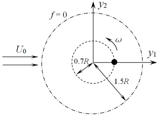
Figure 6.
Sketch of a rotating acoustic monopole in a uniform flow.
Figure 7 shows the time history of the sound pressure generated by a rotating acoustic monopole in a uniform flow with receiver points located at . The results show that the sound pressure predictions made via the MSFW-H and Fast MSFW-H methods have high levels of consistency with the analytical solution data in the time domain. All the above results confirm that the proposed Fast MSFW-H method is accurate for a monopole source in subsonic inflow.
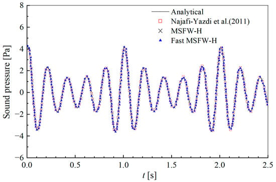
Figure 7.
Comparison of the time history of the sound pressure of a rotating acoustic monopole, obtained via the MSFW-H method and Fast MSFW-H method and measured at [].
3.3. Test Case 3: A Stationary Point Dipole in a Moving Medium
A stationary point dipole source in a moving medium is employed to verify the DSFW-H (Equation (9)) and Fast DSFW-H (Equation (15)) methods. The point dipole axis was aligned with the orientation of the -axis. Lockard [] provided a harmonic velocity potential function from the sound field generated by a stationary acoustic monopole in a uniform flow medium. Then, Najafi-Yazdi et al. [] further extended the velocity potential function for such a dipole source in a uniform flow as follows:
when the sound source moves in the direction of the −x2 axis at a uniform flow velocity . An equivalent flow involves a fixed source at the origin in the direction of the +x2 axis at a flow velocity . This problem is similar to the aerodynamic noise measurement conducted in a wind tunnel test.
In this study, two Mach numbers, and , are verified. Figure 8 shows a comparison of the RMS values of the sound pressure generated by the dipole in a uniform flow medium with receiver points located at . The sound directivity pattern is biased towards the upstream position, and the sound pressure amplitude of the upstream location is larger than that of the downstream location due to the convection effect []. Compared with the analytical solution, the errors generated by the DSFW-H and Fast DSFW-H formulation are less than 0.3%. The DSFW-H and Fast DSFW-H methods are adequate for numerically accurate aeroacoustic predictions.
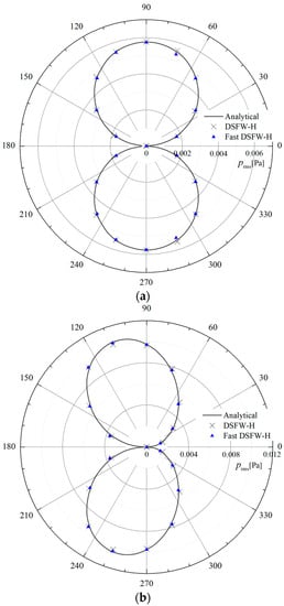
Figure 8.
Comparison of the RMS values of the sound pressure of a point dipole source, obtained via the DSFW-H method and Fast DSFW-H method and measured at : (a) ; (b) .
4. Applications to a Circular Cylinder in a Uniform Flow
4.1. The Aeroacoustic Simulation
To compare the computational efficiencies, we conduct a study of a flow moving past a circular cylinder of a finite length, which has been extensively studied and is reported in refs. [,,,]. The circular cylinder’s diameter D is 20 mm, the circular cylinder’s spanwise length is 9D, the streamwise velocity of the uniform flow is 64 m/s, the pressure at the outlet boundary is 101,325 Pa, the initial flow velocity is (64, 0, 0) m/s and the initial turbulence intensity is 0.1%. Under the above flow conditions, the Reynolds number based on the circular cylinder diameter is 0.876 × 10⁵.
A 2-D schematic diagram of the calculation domain and boundary condition set for modelling the circular cylinder case is shown in Figure 9. The width and height of the calculation domain are 50D and 30D, respectively. The length from the circular cylinder centre to the velocity inlet boundary is set to 15D, and the length from the circular cylinder centre to the pressure outlet boundary is 60D. The total number of cells in this circular cylinder case is approximately 11.8 million. A grid convergence test is also performed by running a case with a mesh of approximately 27.4 million cells, and the test proves that the mesh with 11.8 million cells is sufficiently fine for the current study. The distance from the inner solid wall to the centroid of the first cell is 1 × 10⁻⁶ m, and the distance from the interface to the first cell is 1 × 10⁻⁵ m. The diameter of the permeable integral surface is 3D. In this case, the near-field unsteady flow behaviour around the circular cylinder model is analysed using an IDDES turbulence model based on the two-equation eddy-viscosity model. The sound from the circular cylinder obtained via the FW-H (the sum of the sound pressures of MSFW-H and DSFW-H) and Fast FW-H (the sum of the sound pressures of Fast MSFW-H and Fast DSFW-H) methods were used to compare their computational efficiencies.
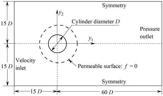
Figure 9.
Calculation domain and boundary condition for modelling a circular cylinder.
4.2. Sound Characteristics in the Time/Frequency Domain
Figure 10a shows the simulation results of the pressure coefficients () around the circular cylinder’s surface. Two different experimental results, those of Giedt [], Cantwell et al. [], and the LES simulation results from Karthik et al. [] are chosen for a comparison with those of the present study. Although the IDDES simulation results do not overlap with the experimental results, they are in reasonably good agreement. In Figure 10b, the time history of the drag coefficients and the lift coefficients ( and , where and are the drag forces and lift forces on the circular cylinder, respectively), around the circular cylinder also prove the validity of the IDDES turbulence model. The RMS lift coefficients are 0.51, and the averaged drag coefficients are 1.08. We can see that the RMS lift coefficients and the averaged drag coefficients are within the appropriate ranges of [0.48, 0.61] and [0.98, 1.19], respectively, as shown in [,].
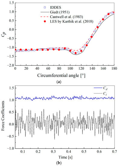
Figure 10.
(a) Comparison of pressure coefficients of the circular cylinder with experiments; (b) time history of drag and lift coefficients [,,].
Figure 11 shows a comparison of the time history of the sound pressure generated by the circular cylinder using the FW-H and Fast FW-H methods. The receiver point is located on (0, 70D, 0). As shown in Figure 11, the time history curves of the sound pressure obtained via the FW-H and Fast FW-H methods exhibit little difference within the range of 0.7 s, and the maximum relative error is 0.35. The sound pressure predictions of the Fast FW-H method correspond fairly well with the data of the FW-H method for the sound pressure amplitude and the shape of the sound pressure distribution.

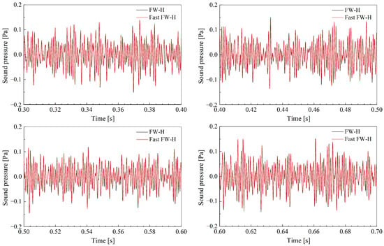
Figure 11.
Comparison of the time history of the sound pressure of a circular cylinder obtained via the FW-H and Fast FW-H methods measured at (0, 70D, 0).
The sound pressure level (SPL) is defined in Equation [] with the unit dB.
where PSD is the power spectral density of the sound pressure , and is the reference sound pressure of . The PSD of the computing time history of the sound pressure is obtained using the Welch method, adopting a Hanning window with five segments, each with 50% overlap.
Figure 12 displays the SPL received by the receiver point placed at (0, 70D, 0). The time step size is set to 1 × 10⁻⁴ s. The total time of the aerodynamic noise prediction is set to 0.7 s. This figure shows that the FW-H and Fast FW-H methods can successfully calculate a flow passing a finite-length circular cylinder in a uniform flow medium, and the two approaches capture the vortex shedding noise accurately. The simulated results are compared to the experimental data available in the results in [], and good agreements are observed in terms of the frequencies of the primary tone and its harmonics, the tonal noise amplitude and the shape of the spectral distribution.
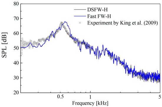
Figure 12.
SPL of the sound pressure generated by the circular cylinder [].
4.3. Convergence and Computational Efficiency
To compare the convergence of the Fast FW-H method, the receiver points are located on a hemisphere concentric with the circular cylinder, and the distance between the receiver points and the origin of the coordinate system is 10D. Figure 13 shows the sound radiation patterns with different numbers of receiver points (RPNs) at t = 0.3 s. The sound pressure of the receiver surface is solved via the Fast FW-H method. The maximum positive sound pressure occurs in the direction perpendicular to the direction of the flow movement in the +y1 axis orientation. In addition, the maximum negative sound pressure appears in the windward direction of the circular cylinder in the −y1 axis orientation. With an increase in the RPN, the sound pressure distribution on the hemispherical sphere reaches computational convergence in a certain time with little difference, and the noise radiation direction is a typical dipole pattern of directivity for the circular cylinder. This is because the aerodynamic noise generated from vortex shedding is a dipole source.
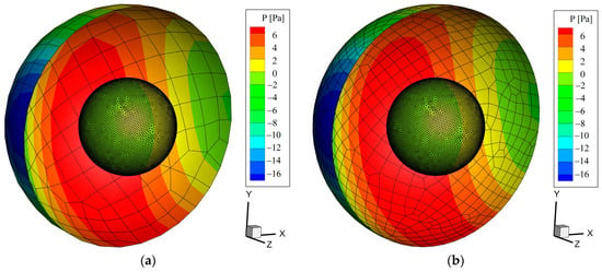
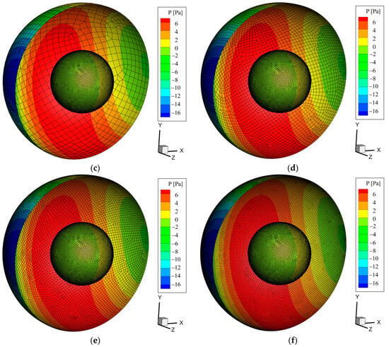
Figure 13.
Sound radiation patterns with different RPNs at t = 0.3 s: (a) RPN = 197; (b) RPN = 711; (c) RPN = 1110; (d) RPN = 4263; (e) RPN = 7301; (f) RPN = 16,003.
The values of the total wall-clock time used by the FW-H and Fast FW-H approaches in these calculations to solve the noise source generated by the above circular cylinder with different numbers of cells from the integral surface and different RPNs are plotted in Figure 14, which shows the significant advantage of the Fast FW-H method over the FW-H method with respect to time savings. For example, for the largest model with 60,789 integral surface cells, the Fast FW-H method took less than 2600 s, while the FW-H method took approximately 4958 s of wall-clock time, as shown in Figure 14a. With an increase in the RPNs, there exists a linear relationship between the wall-clock time of all sound pressure calculations and the RPNs, as shown in Figure 14b, because the FW-H and Fast FW-H methods gradually integrate and calculate the sound pressure of the receiver points using a numerical algorithm. In this studied case, the Fast FW-H method is found to be approximately 51% faster than the FW-H method for solving the circular cylinder model (with 16,003 receiver points and 16,262 integral surface cells) of a flow passing a finite-length circular cylinder.
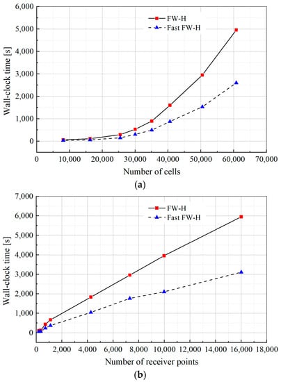
Figure 14.
Comparison of the values for the total wall-clock time used to solve the noise source generated by a circular cylinder vs: (a) the number of cells; (b) the number of receiver points.
Additionally, compared with the FW-H method, the Fast FW-H method can solve larger-scale aeroacoustic problems with larger RPNs. This is because the node-to-node interactions in the FW-H method are replaced with cell-to-cell interactions in the Fast FW-H method by a hierarchical tree structure of cells containing groups of nodes []. The adoption of FMM acceleration will greatly reduce the computer storage space and the calculation dimension. The Fast FW-H method accelerated by the FMM has a powerful advantage in solving large NRPs in the far field and can be used to predict the aerodynamic noise for a large number of receiver locations.
5. Applications to a UAV Propeller during Forward Flight
5.1. The Aeroacoustic Experiment and Simulation
An aeroacoustic performance test for a UAV propeller was conducted in a 14 m × 5.5 m × 4 m (L × W × H) full anechoic chamber (Figure 15) with a cut-off frequency of 100 Hz. The diameter of the UAV propeller was 0.206 m. The 3/4 length of the radial position chord of the UAV propeller was 0.0163 m and the maximum design speed was 6000 RPM, as shown in Figure 15a. The full-scale UAV propeller model was supported by a cantilever column in the full anechoic chamber, and one microphone was used to measure the flow-induced sound pressure, as shown in Figure 15b. The microphone is arranged 0.8 m from the centre of the UAV’s propeller.
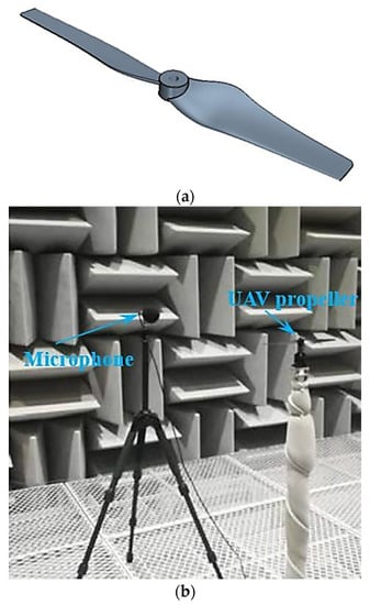
Figure 15.
A full-scale UAV propeller in a full anechoic chamber: (a) UAV propeller; (b) anechoic chamber experiment.
For the computational model, the flow field calculation domain and boundary condition of the UAV propeller are shown in Figure 16. The fluid space comprises stationary and rotating computational regions, and the fluid field of the UAV propeller is set as a rotating computational region, while the fluid fields of the other parts are set as stationary computational regions. The slipping grid technique is used to implement the relative motion between the stationary and rotating computational regions in a numerical simulation with one interface between them during forward flight. A spherical computational domain with a diameter of 3R is adopted in the rotating computational region, and the interface surface is used for data transfer between the rotating computational region and the stationary computational regions. The rotating speed of the UAV propeller is set as 5000 RPM. The pitch angle of the propeller is 10°, according to the anechoic chamber experimental conditions. The wind velocity is 20 m/s, corresponding to the forward flight speed in this study.
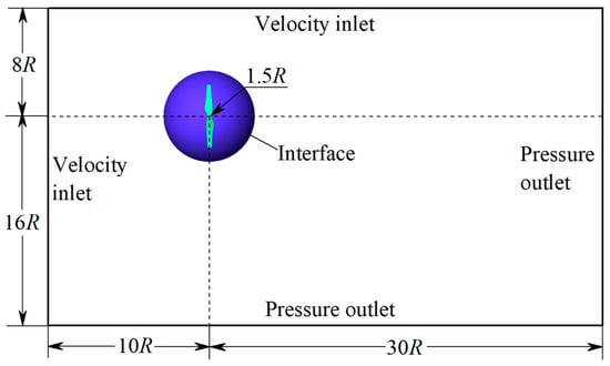
Figure 16.
Calculation domain and boundary condition for modelling a UAV propeller.
A grid dispersion and grid-independent verification of the UAV propeller model were conducted and the details are not elaborated here. The total number of cells in this UAV propeller case is approximately 39.2 million. The IDDES, the FW-H and the Fast FW-H methods are used under the aforementioned conditions to compute the UAV propeller’s aeroacoustic responses. The interface is selected as the permeable integral surface.
5.2. Sound Characteristics in the Time/Frequency Domain
The time history of the calculated sound pressure at r = 0.8 m is shown in Figure 17. As can be seen, the sound pressure changes periodically due to the vortex shedding in the flow passing the UAV propeller. The sound pressure amplitude is approximately 0.17 Pa. The time cycle of the sound pressure is 0.006 s, corresponding to a frequency of 166.7 Hz. For the UAV propeller composed of two blades, the radiation noise has a dominant frequency of 333 Hz.
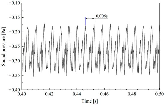
Figure 17.
Time history of sound pressure generated by a UAV propeller.
Figure 18 presents the spectral comparison of the aerodynamic noise obtained via the simulation and experimental data. The background noise plotted by the dotted line is at least 10 dB lower than the UAV propeller’s noise. The noise spectra have maximum values at 1 BPF (BPF is the blade passing frequency, , where is the UAV propeller rotating speed of 5000 RPM, and is the number of propeller blades, which is two in this study), corresponding to a main frequency of approximately 333 Hz. In addition, the BPF magnitude decreases with higher harmonics.
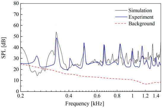
Figure 18.
Spectral comparison of the simulation result and the experimental result.
In addition, the SPL predictions of the Fast FW-H method correspond fairly well with the experimental result in the range of 1500 Hz. The high consistencies are mainly reflected in the following three aspects: the distribution range of the tonal frequency peak, the tone amplitudes and the shape of the harmonic behaviour [].
Figure 19 displays the spectra of the monopole and dipole source terms from the total noise spectrum parts shown in Figure 18. As can be seen from Figure 19, the aerodynamic noise is mainly the contribution of the dipole noise as the aerodynamic noise radiated by the UAV propeller is mainly determined by the pressure fluctuations on the surface of the source of the noise.
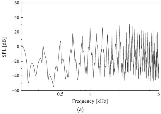
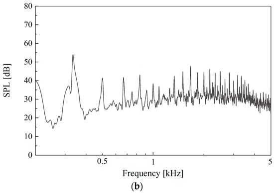
Figure 19.
The spectra of monopole and dipole noise from the total noise: (a) monopole source; (b) dipole source.
5.3. Computation of Sound in the Far Field
In this subsection, the far-field sound propagation features of the UAV during forward flight in a moving medium which contains numerous receiver points are computed using the FW-H and Fast FW-H methods, respectively. The primary aim of this subsection is to investigate the computational efficiency of the Fast FW-H and to validate the numerical simulation results of the above-mentioned methods in a moving medium. Figure 20 gives the far-field sound receiver points in which a receiver point is an annulus with inner and outer radii of 10R (1 m) and 30R (3 m), respectively. The RPN in the sound field is 156 (circumferential direction) × 40 (radial direction) = 6240. The sound pressure of the far-field sound field is computed in the time domain.
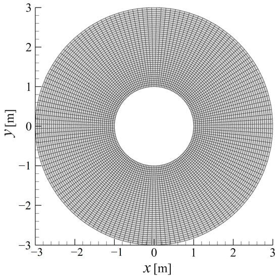
Figure 20.
A mesh of the far-field receiver points.
Figure 21 displays the sound pressure field around the UAV propeller during forward flight, as obtained via the FW-H and Fast FW-H methods. This figure shows that the horizontal dipole patterns of the sound radiating from the rotating UAV propeller are dominant. The maximum sound pressure appears on the windward or leeward side of the UAV propeller during forward flight. All the aforementioned results indicate that the results obtained from the Fast FW-H method are consistent with those obtained from the FW-H method, further validating the proposed Fast FW-H method. In addition, the fast FW-H method is found to be approximately 48% faster than the FW-H method for solving the UAV propeller model with 6240 RPN and 36,510 cells. Therefore, it can be seen that for multiple RPNs, the computational efficiency advantage of the Fast FW-H method is more obvious. Compared with the FW-H method, the computational time taken to solve the far-field sound field is reduced by about half.
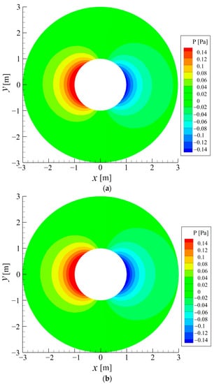
Figure 21.
The sound pressure field around the UVA propeller: (a) FW-H method; (b) Fast FW-H method.
6. Conclusions
A new method for calculating the monopole and dipole source terms appearing in the FW-H formulation accelerated via the FMM in the time domain is presented in this paper; this method has not been reported in the literature.
The performance and efficiency of the proposed method with respect to calculating the monopole source terms in FW-H formulation accelerated via the FMM in the time domain are demonstrated by studying sound predictions for a stationary and moving acoustic monopole in a uniform flow. The test case of the stationary acoustic monopole indicates that the sound directivity pattern is biased towards the upstream position, and the amplitude of the sound pressure is larger than the amplitude of the sound pressure downstream due to the convection effect. The predictions match very well with the analytical solution in general, with a relative error of less than 0.4%.
The correctness of the aeroacoustic equation for a rotating acoustic monopole in a uniform flow is verified for the monopole source terms in FW-H formulation accelerated via the FMM in the time domain. The results show that the sound pressure predictions made using the above methods have high levels of consistency with the data using the analytical solution in the time domain.
A stationary point dipole source in a moving medium is verified using the dipole source terms in a FW-H formulation accelerated via the FMM in the time domain. The sound directivity pattern is biased towards the upstream position, and the amplitude of the sound pressure of the upstream location is larger than the amplitude of the sound pressure of the downstream location due to the convection effect. The predictions match very well with the analytical solution in general, with a relative error of less than 0.3%.
Next, the application of the developed approach to aeroacoustic problems include the generation of noise by a finite-length circular cylinder. The time history curves of the sound pressure generated by the finite-length circular cylinder obtained via the FW-H and Fast FW-H methods exhibit negligible differences within the range of 0.7 s, and the maximum relative error is 0.35%. Good agreements are observed in terms of the frequencies of the primary tone and its harmonics, the tonal noise amplitude and the shape of the spectral distribution.
Then, the method’s application the aeroacoustic problems includes the noise generated by a UAV propeller during forward flight. The high consistencies are mainly reflected in the following three aspects: the tonal frequency peak distribution range, the tone amplitudes and the shape of the harmonic behaviour.
Additionally, the fast FW-H method is found to be approximately 50% faster than the FW-H method in solving the circular cylinder model (with 16,003 RPN and 11.8 million cells) and the UAV propeller model (with 6240 RPN and 39.2 million cells), respectively.
The proposed method of accelerating monopole source and dipole source terms via the FMM can also be extended to accelerate volume quadrupole source terms. The acceleration of the remaining noise source terms in the FW-H formulation will be the focus of future work to improve the Fast FW-H method.
Author Contributions
Methodology, Y.Z. and Y.L.; software, Y.Z. and Y.L.; validation, Y.Z.; formal analysis, Y.Z.; investigation, Y.Z.; resources, Y.L.; writing—original draft preparation, Y.Z.; writing—review and editing, Y.Z. and Y.L.; supervision, Y.L. All authors have read and agreed to the published version of the manuscript.
Funding
The authors would like to acknowledge the support via funding from the National Natural Science Foundation of China (Project No. 11972179) and the Guangdong Basic and Applied Basic Research Foundation (Project No. 2019A1515111005).
Data Availability Statement
Not applicable.
Conflicts of Interest
The authors declare no conflict of interest.
Nomenclature
| speed of sound | |
| flow velocity | |
| surface velocity | |
| unit external normal vector | |
| receiver point time | |
| location integral surface retarded time | |
| location of the receiver points | |
| location of the integral surface | |
| expansion centre close to the node | |
| distance between the source and the receiver, | |
| evaluated at the retarded time | |
| complex conjugate | |
| Mach number, | |
| Lighthill stress tensor | |
| Kronecker delta symbol | |
| viscous stress tensor | |
| Dirac delta function | |
| Heaviside function | |
| sound pressure | |
| static fluid pressure | |
| static fluid density | |
| number of expansion terms | |
| multipole moments centred at | |
| Subscripts | |
| 0 | initial number |
| index number in three-dimensional space | |
| normal direction | |
| observer quantity | |
| source quantity | |
| vector quantity | |
| thickness (monopole) source quantity | |
| loading (dipole) source quantity | |
| Abbreviations | |
| FMM | fast multipole method |
| CFD | computational fluid dynamics |
| FW-H | Ffowcs Williams–Hawkings |
| MSFW-H | monopole source terms of FW-H |
| DSFW-H | dipole source terms of FW-H |
| CBIE | conventional boundary integral equation |
| M2M | moment-to-moment |
| M2L | moment-to-local |
| L2L | local-to-local |
| PSD | power spectral density |
| RPN | number of receiver point |
| IDDES | improved delayed, detached eddy simulation |
References
- Stuermer, A.; Yin, J.; Akkermans, R. Progress in aerodynamic and aeroacoustic integration of CROR propulsion systems. Aeronaut. J. 2014, 118, 1137–1158. [Google Scholar] [CrossRef]
- Zhong, S.; Zhang, X. A sound extrapolation method for aeroacoustics far-field prediction in presence of vortical waves. J. Fluid Mech. 2017, 820, 424–450. [Google Scholar] [CrossRef]
- Lighthill, M.J. On sound generated aerodynamically I. General theory. Proc. R. Soc. Lond. Ser. A Math. Phys. Sci. 1952, 211, 564–587. [Google Scholar]
- Curle, N. The influence of solid boundaries upon aerodynamic sound. Proc. R. Soc. Lond. Ser. A Math. Phys. Sci. 1955, 231, 506–514. [Google Scholar]
- Ffowcs-Williams, J.E.; Hawkings, D.L. Sound generation by turbulence and surfaces in arbitrary motion. Philos. Trans. R. Soc. Lond. Ser. A Math. Phys. Sci. 1969, 264, 321–342. [Google Scholar]
- Hawkings, D.L. Noise generation by transonic open rotors. In Mechanics of Sound Generation in Flows, Proceedings of the Joint Symposium, Goettingen, Germany, 28–31 August 1979; Springer: Berlin/Heidelberg, Germany, 1979; pp. 294–300. [Google Scholar]
- Farassat, F.; Myers, M.K. Extension of Kirchhoff’s formula to radiation from moving surfaces. J. Sound Vib. 1988, 123, 451–460. [Google Scholar] [CrossRef]
- Brentner, K.S.; Farassat, F. Analytical comparison of the acoustic analogy and Kirchhoff formulation for moving surfaces. AIAA J. 1998, 36, 1379–1386. [Google Scholar] [CrossRef]
- Brentner, K.S. An efficient and robust method for predicting helicopter high-speed impulsive noise. J. Sound Vib. 1997, 203, 87–100. [Google Scholar] [CrossRef]
- Brentner, K.S.; Farassat, F. Modeling aerodynamically generated sound of helicopter rotors. Prog. Aerosp. Sci. 2003, 39, 83–120. [Google Scholar] [CrossRef]
- Di Francescantonio, P. A new boundary integraI formuIation for the prediction of sound radiation. J. Sound Vib. 1997, 202, 491–509. [Google Scholar] [CrossRef]
- Farassat, F.; Succi, G.P. The prediction of helicopter rotor discrete frequency noise. Vertica 1983, 7, 309–320. [Google Scholar]
- Farassat, F. Derivation of Formulations 1 and 1A of Farassat; NASA/TM-2007-214853; National Aeronautics and Space Administration: Hampton, VA, USA, 2007.
- Casalino, D. An advanced time approach for acoustic analogy predictions. J. Sound Vib. 2003, 261, 583–612. [Google Scholar] [CrossRef]
- Gennaretti, M.; Testa, C.; Bernardini, G. Frequency-domain method for discrete frequency noise prediction of rotors in arbitrary steady motion. J. Sound Vib. 2012, 331, 5502–5517. [Google Scholar] [CrossRef]
- Tang, H.; Qi, D.; Mao, Y. Analysis on the frequency-domain numerical method to compute the noise radiated from rotating sources. J. Sound Vib. 2013, 332, 6093–6103. [Google Scholar] [CrossRef]
- Chen, X.; Mao, Y.; Qi, D. Frequency-domain acoustic pressure formulation for rotating source in uniform subsonic inflow with arbitrary direction. J. Sound Vib. 2014, 333, 3081–3091. [Google Scholar]
- Mao, Y.; Xu, C.; Qi, D. Computation of instantaneous and time-averaged active acoustic intensity field around rotating source. J. Sound Vib. 2015, 337, 95–115. [Google Scholar] [CrossRef]
- Mao, Y.; Xu, C.; Qi, D. Analytical solution for sound radiated from the rotating point source in uniform subsonic axial flow. Appl. Acous. 2015, 82, 6–11. [Google Scholar] [CrossRef]
- Huang, Z.; Siozos-Rousoulis, L.; De Troyer, T.; Ghorbaniasl, G. Helicopter rotor noise prediction using a convected FW-H equation in the frequency domain. Appl. Acous. 2018, 140, 122–131. [Google Scholar] [CrossRef]
- Siozos-Rousoulis, L.; Amoiridis, O.; Huang, Z.; De Troyer, T.; Kalfas, A.I.; Ghorbaniasl, G. A convected frequency-domain equivalent source approach for aeroacoustic scattering prediction of sources in a moving medium. J. Sound Vib. 2018, 431, 88–104. [Google Scholar] [CrossRef]
- Lyrintzis, A. Surface integral methods in computational aeroacoustics—From the (CFD) near-field to the (acoustic) far-field. Int. J. Aeroacoust. 2003, 2, 95–128. [Google Scholar] [CrossRef]
- Spalart, P.R.; Travin, A.K.; Shur, M.L.; Strelets, M.K. Initial noise predictions for open rotors using first principles. In Proceedings of the 16th AIAA/CEAS Aeroacoustics Conference AIAA, Stockholm, Sweden, 7–9 June 2010. [Google Scholar]
- Dawi, A.; Akkermans, R.A.D. Spurious noise in direct noise computation with a finite volume method for automotive applications. Int. J. Heat Fluid Flow 2018, 72, 243–256. [Google Scholar] [CrossRef]
- Dawi, A.H.; Akkermans, R.A.D. Direct and integral noise computation of two square cylinders in tandem arrangement. J. Sound Vib. 2018, 436, 138–154. [Google Scholar] [CrossRef]
- Sezen, S.; Atlar, M.; Fitzsimmons, P. Prediction of cavitating propeller underwater radiated noise using RANS & DES-based hybrid method. Ships Offshore Struct. 2021, 16 (Suppl. S1), 93–105. [Google Scholar]
- Fu, J.; Vigevano, L. Aeroacoustic modeling of helicopter transonic rotor noise. Aerosp. Sci. Technol. 2002, 122, 107430. [Google Scholar] [CrossRef]
- Greengard, L.; Rokhlin, V. A fast algorithm for particle simulations. J. Comput. Phys. 1987, 73, 325–348. [Google Scholar] [CrossRef]
- Rokhlin, V. A fast algorithm for the discrete Laplace transformation. J. Complex. 1988, 4, 12–32. [Google Scholar] [CrossRef]
- Cheng, H.; Greengard, L.; Rokhlin, V. Regular article: A fast adaptive multipole algorithm in three dimensions. J. Comput. Phys. 1999, 155, 468–498. [Google Scholar] [CrossRef]
- Shen, L.; Liu, Y.J. An adaptive fast multipole boundary element method for three-dimensional acoustic wave problems based on the Burton–Miller formulation. Comput. Mech. 2006, 40, 461–472. [Google Scholar] [CrossRef]
- Greengard, L.; Rokhlin, V. A new version of the Fast Multipole Method for the Laplace equation in three dimensions. Acta Numer. 1997, 6, 229–269. [Google Scholar] [CrossRef]
- Liu, Y.J.; Nishimura, N. The fast multipole boundary element method for potential problems: A tutorial. Eng. Anal. Bound. Elem. 2006, 30, 371–381. [Google Scholar] [CrossRef]
- Liu, Y.J. Fast Multipole Boundary Element Method: Theory and Applications in Engineering; Cambridge University Press: Cambridge, UK, 2009. [Google Scholar]
- Nishimura, N. Fast multipole accelerated boundary integral equation methods. Appl. Mech. Rev. 2002, 55, 299–324. [Google Scholar] [CrossRef]
- Liu, Y.J. On the BEM for acoustic wave problems. Eng. Anal. Bound. Elem. 2019, 107, 53–62. [Google Scholar] [CrossRef]
- Cheng, H.; Crutchfield, W.Y.; Gimbutas, Z.; Greengard, L.F.; Ethridge, J.F.; Huang, J.; Rokhlin, V.; Yarvin, N.; Zhao, J. A wideband fast multipole method for the Helmholtz equation in three dimensions. J. Comput. Phys. 2006, 216, 300–325. [Google Scholar] [CrossRef]
- Wolf, W.R.; Lele, S.K. Acoustic analogy formulations accelerated by fast multipole method for two-dimensional aeroacoustic problems. AIAA J. 2010, 48, 2274–2285. [Google Scholar] [CrossRef]
- Wolf, W.R.; Lele, S.K. Aeroacoustic integrals accelerated by fast multipole method. AIAA J. 2011, 49, 1466–1477. [Google Scholar] [CrossRef]
- Wolf, W.R.; Azevedo, J.L.F.; Lele, S.K. Convective effects and the role of quadrupole sources for aerofoil aeroacoustics. J. Fluid Mech. 2012, 708, 502–538. [Google Scholar] [CrossRef]
- Mao, Y.; Xu, C. Accelerated method for predicting acoustic far field and acoustic power of rotating source. AIAA J. 2016, 54, 603–615. [Google Scholar] [CrossRef]
- Spalart, P.R. Comments on the feasibility of LES for wings, and on a hybrid RANS/LES approach. In Proceedings of the First AFOSR International Conference on DNS/LES, Ruston, LA, USA, 4–8 August 1997; pp. 4–8. [Google Scholar]
- Shur, M.L.; Spalart, P.R.; Strelets, M.K.; Travin, A.K. A hybrid RANS-LES approach with delayed-DES and wall-modelled LES capabilities. Int. J. Heat Fluid Flow 2008, 29, 1638–1649. [Google Scholar] [CrossRef]
- Spalart, P.R. Detached-eddy simulation. Ann. Rev. Fluid Mech. 2009, 41, 181–202. [Google Scholar] [CrossRef]
- Farassat, F. Linear acoustic formulas for calculation of rotating blade noise. AIAA J. 1981, 19, 1122–1130. [Google Scholar] [CrossRef]
- Najafi-Yazdi, A.; Brès, G.A.; Mongeau, L. An acoustic analogy formulation for moving sources in uniformly moving media. Proc. R. Soc. A Math. Phys. Eng. Sci. 2010, 467, 144–165. [Google Scholar] [CrossRef]
- Zhong, S.; Zhang, X. A generalized sound extrapolation method for turbulent flows. Proc. R. Soc. A Math. Phys. Eng. Sci. 2018, 474, 20170614. [Google Scholar] [CrossRef]
- Shen, L.; Liu, Y.J. An adaptive fast multipole boundary element method for three-dimensional potential problems. Comput. Mech. 2006, 39, 681–691. [Google Scholar] [CrossRef]
- Yoshida, K. Applications of Fast Multipole Method to Boundary Integral Equation Method; Department of Global Environment Engineering, Kyoto University: Kyoto, Japan, 2001. [Google Scholar]
- Lockard, D. A comparison of Ffowcs Williams-Hawkings solvers for airframe noise applications. In Proceedings of the 8th AIAA/CEAS Aeroacoustics Conference and Exhibition, Washington, DC, USA, 17–19 June 2022; pp. 2002–2580. [Google Scholar]
- Ghorbaniasl, G.; Lacor, C. A moving medium formulation for prediction of propeller noise at incidence. J. Sound Vib. 2012, 331, 117–137. [Google Scholar] [CrossRef]
- Jacob, M.C.; Boudet, J.; Casalino, D.; Michard, M. A rod-airfoil experiment as a benchmark for broadband noise modeling. Theor. Comput. Fluid Dyn. 2004, 19, 171–196. [Google Scholar] [CrossRef]
- King, W.; Pfizenmaier, E. An experimental study of sound generated by flows around cylinders of different cross-section. J. Sound Vib. 2009, 328, 318–337. [Google Scholar] [CrossRef]
- Zhang, Y.; Zhang, J.; Li, T.; Zhang, L. Investigation of the aeroacoustic behavior and aerodynamic noise of a high-speed train pantograph. Sci. China Technol. Sci. 2017, 60, 561–575. [Google Scholar] [CrossRef]
- Iglesias, E.L.; Thompson, D.; Smith, M. Experimental study of the aerodynamic noise radiated by cylinders with different cross-sections and yaw angles. J. Sound Vib. 2016, 361, 108–129. [Google Scholar] [CrossRef]
- Giedt, W.H. Effect of turbulence level of incident air stream on local heat transfer and skin friction on a cylinder. J. Aeronaut. Sci. 1951, 18, 725–730. [Google Scholar] [CrossRef]
- Cantwell, B.J.; Coles, D. An experimental study of entrainment and transport in the turbulent near wake of a circular cylinder. J. Fluid Mech. 1983, 136, 321–374. [Google Scholar] [CrossRef]
- Karthik, K.; Vengadesan, S.; Bhattacharyya, S.K. Prediction of flow induced sound generated by cross flow past finite length circular cylinders. J. Acoust. Soc. Am. 2018, 143, 260–270. [Google Scholar] [CrossRef] [PubMed]
- Norberg, C. Flow around a circular cylinder: Aspects of fluctuating lift. J. Fluids Struct. 2001, 15, 459–469. [Google Scholar] [CrossRef]
- Yang, Y.; Liu, Y.; Li, Y.; Arcondoulis, E.; Wang, Y. Aerodynamic and aeroacoustic performance of an isolated multicopter rotor during forward flight. AIAA J. 2020, 58, 1171–1181. [Google Scholar] [CrossRef]
Disclaimer/Publisher’s Note: The statements, opinions and data contained in all publications are solely those of the individual author(s) and contributor(s) and not of MDPI and/or the editor(s). MDPI and/or the editor(s) disclaim responsibility for any injury to people or property resulting from any ideas, methods, instructions or products referred to in the content. |
© 2023 by the authors. Licensee MDPI, Basel, Switzerland. This article is an open access article distributed under the terms and conditions of the Creative Commons Attribution (CC BY) license (https://creativecommons.org/licenses/by/4.0/).