1. Introduction
Automotive silencers, also known as mufflers, are a key component of an automobile as they reduce harmful noise outputs from the engine to the environment. Unattenuated engine noise can be over 100 dB and this noise level is detrimental to the health of both humans and wildlife [
1,
2,
3]. The World Health Organization have noted that noise is a “growing concern”. Several adverse health effects have been linked to an over exposure [
4].
The goal of an automotive silencer varies depending on automotive type; however, in general, the main goal is to enhance the attenuation performance of the exhaust system while minimising the effect on engine power output. The silencer industry is growing despite the shift towards electric vehicles [
5]. This is due to the increase in the number of automobiles and disposable income within developing countries. Therefore, research to enhance silencer performance remains an important topic. This work focuses on the implementation of acoustic metamaterials in an automotive silencer to improve the performance. Advancements in additive manufacturing and large investments in this technology from automotive companies make acoustic metamaterials a new and viable way to improve sound attenuation within the exhaust system [
6,
7,
8].
There are two main categories of silencer—absorptive and reactive silencers—with most commercial silencers incorporating elements of both. Absorptive silencers allow sound waves to propagate throughout the material which causes friction between the vibrating air molecules and the molecules in the porous material. The sound energy is dissipated in the form of heat due to the friction within the porous medium [
9]. In general, an absorptive silencer is not a sufficient sound attenuator for an automotive application. It increases the overall transmission loss across a broad range of frequencies, especially higher frequencies, and has an almost negligible contribution to backpressure in the exhaust system. However, it does not target specific frequencies and does not yield high transmission loss values at lower frequencies in comparison to reactive silencers [
10].
Reactive silencers utilise geometric discontinuities within the silencer to increase the number of wave interactions and therefore increase the likelihood of destructive interference between sound waves [
11]. Automotive companies utilise baffles, internal cylinders/ducts, side resonators and expansion and contraction chambers to attenuate specific unwanted frequencies. A major drawback of including these geometric discontinuities is an increase in the amount of backpressure within the system. The power output of an engine is directly proportional to the amount of oxygen in the system, backpressure reduces the oxygen capacity of the engine and therefore the power output. Increasing the amount of geometrical discontinuities increases the restriction on the exhaust flow and thus the amount of backpressure [
10]. Combining the two types of silencers allows engineers to increase overall transmission loss, target certain frequencies for sound attenuation and obtain decent ratios between transmission loss and backpressure.
The next generation of automotive silencers may incorporate acoustic metamaterials. A metamaterial is a human-made compound, a structured material engineered to achieve a response not available in nature and for which the model of an equivalent continuum can be defined [
12]. In order to unlock the potential for metamaterials within the automotive industry efficient, low computational costs design tools are required. With these tools designers will be able to enhance target frequencies within the silencer through the addition of acoustic metamaterials. A novel reactive silencer could incorporate acoustic metamaterials into the existing baffles and structures within the silencer. These metamaterial enhanced silencers could incorporate repeated structures into a baffle containing a cellular lattice. The behavior of this lattice can be modelled by building up a macro model from a detailed analysis of the repeated cell. In order to develop the toolchain required for industrial design, benchmark materials are required to validate numerical codes [
13,
14].
The future potential for silencers based on metamaterials is highlighted by recent papers on on optimal sound absorber design [
15,
16,
17,
18,
19]. These papers demonstrate the potential for additive manufacturing to realise complex metamaterial designs suitable for inclusion in automotive silencers. This research aims to evaluate and validate the performance of acoustic metamaterials in a representative automotive silencer using industrially relevant design tools. This will be executed by creating a modular representative silencer which enables the testing of various traditional sound attenuating techniques. The numerical results achieved using COMSOL Multiphysics software [
20] will be validated experimentally. The validated traditional techniques will then be modified to include acoustic metamaterials. Comparisons between the traditional and modified technique results will help to gauge the effectiveness of the acoustic metamaterials. The metamaterial results will then be compared with an analytical model which predicts the performance of the chosen DENORMS metamaterial design [
14]. This design has been put forward as a benchmark material design suitable for the development of modelling strategies by the EU COST Action Design for noise reducing materials and structures (DENORMS).
This study aims to show that the performance of an automotive silencer can be enhanced with an acoustic metamaterial and that this metamaterial can be designed and implemented using low cost modelling tools. The work will begin by outlining the design and describing an analytical model for its performance. The performance of the model will be validated using a normal incidence impedance tube test on a sample of additively manufactured material. The impact of the manufacturing tolerances and the change to grazing incidence will be investigated experimentally with a correction applied to the surface impedance values. The grazing surface impedance values will be implemented as a boundary condition within a model of an automotive silencer. The numerical results will be experimentally validated.This study demonstrates that acoustic metamaterials can be used in an automotive silencer to improve the sound attenuation performance with tuneable frequency characteristics.
2. Modular Silencer Design
The most important acoustic performance characteristics for a silencer are insertion loss and transmission loss. Insertion loss is the difference in sound pressure at a point near the termination with and without a silencer installed. It is a property of the source and termination impedance as well as the lengths of the inlet/outlet ducts of the silencer [
21]. This is an extremely useful measurement in the field and many automotive manufacturers will use this method to test the performance of the whole exhaust system. However, for this research it is not the most suitable performance characteristic as it measures the entire exhaust system and does not target the silencer performance in particular.
In this case, transmission loss is a better performance characteristic as it isolates the sound attenuation properties of the silencer. The transmission loss is the difference in the sound power level between the incident wave entering and the transmitted wave exiting the silencer when the silencer termination is anechoic [
21], and can be given by the equation [
22]:
where
is the incident sound power and
is the transmitted sound power. The units for the transmission loss are given in decibel (dB).
The transmission loss can be modelled and simulated with the software COMSOL Multiphysics and this tool is commonly used in the literature for the analysis of both acoustic metamaterials and automotive silencers [
23,
24,
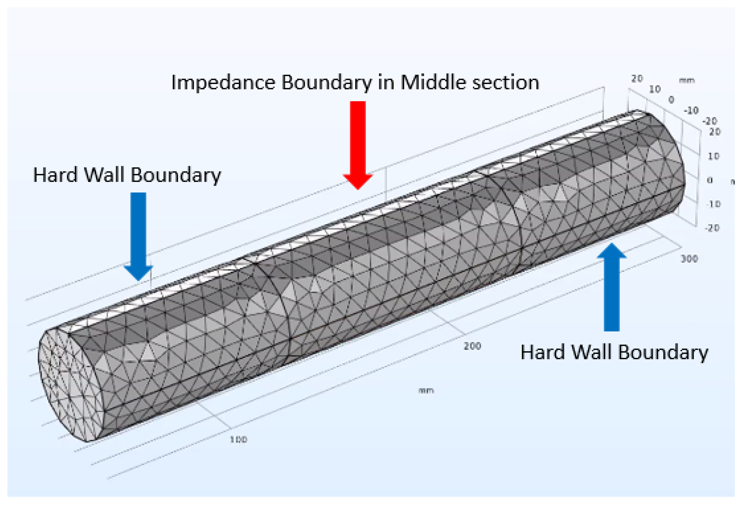
25]. This model solves the problem in the frequency domain using the Pressure Acoustics module within COMSOL with the frequency domain interface. The model equation is a slightly modified version of the Helmholtz equation. At the solid boundaries the model uses sound hard wall boundary conditions. The condition imposes that the normal velocity at the boundary is zero. The inclusion of the metamaterial can be achieved at low cost through the use of a surface impedance boundary condition within the model. This avoid the need for expensive thermoviscous modelling within the porous structure.
The transmission loss can be measured experimentally using the decomposition method, the two-source method and the two-load method [
26]. Based on the findings of Z. Tao and A. F. Seybert [
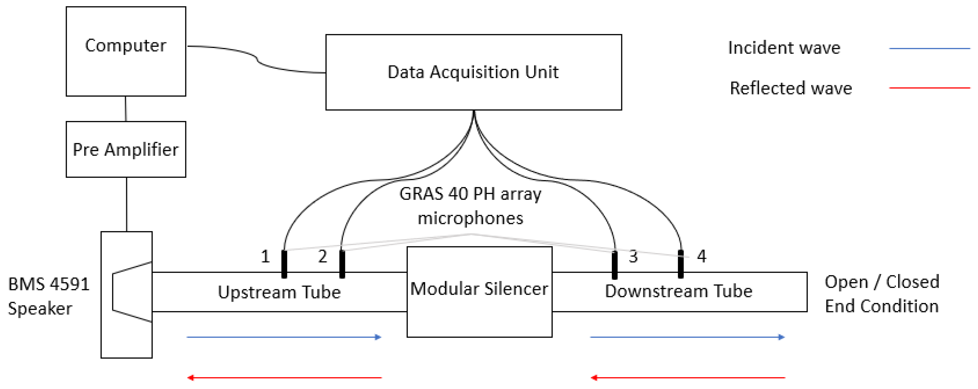
22], it was determined that the most suitable test rig to use for this application was the two-load method. In this method the silencer performance is measured using a test rig as shown in
Figure 1. The measurements are made with two end conditions for the test rig—a hard wall and an anechoic termination. In this case the anechoic termination is achieved with a 35 cm long cone of melamine acoustic foam mounted at the end of the test rig.
The test rig was constructed to comply with the ASTM standard E2611 for the determination of the silencer transmission loss in an impedance tube. In the two-load method there are four waves, two incident and two reflected labelled in
Figure 1. The two-load method utilised the transfer matrix approach. Any acoustic element can be modelled off its four-pole parameters:
p is the sound pressure amplitude at the inlet (
) and outlet (
) of the silencer, and
u is the velocities amplitude at the inlet (
) and outlet (
).
is the cell transfer matrix of the acoustic system, giving the four pole parameters. By changing the load condition from the hard wall to the anechoic termination and repeating the measurement, the four poles can be easily obtained. The transmission loss can then be expressed in terms of these four poles and the tube areas [
27]:
where
and
are the silencer inlet and outlet tube areas respectively,
is the fluid density and
c is the speed of sound in air. Using the transfer matrix approach, the experimental transmission loss can be obtained and compared with the COMSOL simulation results.
The test rig was instrumented with GRAS 40 PH array microphones. The calibration of the microphones was executed by using the switching methods, as described in the standards [
28,
29], to achieve a calibration transfer function which corrects for any differences in the behavior of the microphones. The correction for the microphone mismatch is determined by interchanging microphone 1 with each of the other positions within the tube. The calibration transfer functions between microphone 1 and each other microphone are determined and then applied to the subsequent measurements.
These microphones have a frequency response of ±1 dB within 50–5000 Hz and an upper limit of the dynamic range of 135 dB [
12]. These values for frequency and sound pressure lie within the range experienced by a silencer and therefore are suitable for this application.
The standards specify a cut off frequency for the impedance tube used to avoid the occurrence of non-plane wave mode propagation. For the 40 mm diameter tube used in this experiment the cut off frequency is 4800 Hz. The lower limit is dependent on the speaker, which in this experiment is the BMS 4591 speaker and has a lower limit of 300 Hz [
12]. This limitation had a bearing on the geometry of the silencer, as the frequencies were required to be over 300 Hz for experimental validation of COMSOL results.
Silencers come in a wide variety of shapes and sizes depending on a wide variety of factors which include the mass of exhaust gas, maximum horsepower, RPM, the type of automobile etc. There is no universal sizing for a silencer however there are a number of key components which all silencers share. The length should be 2–2.5 times greater than the width [
10] to allow sufficient gas flow. In general, the larger the silencer, the more sound it attenuates as there is more chance for interaction between sound waves. The main constraint on the size of a silencer is the spacing and the weight.
The representative modular silencer created was designed as a cuboid. This shape allowed for easy manufacturing and modification of the modular aspects of the design. It has been noted and accepted that a circular shape is better for sound attenuation [
30], however a compromise for simplicity of construction has been made. Different variations of length, width and height were investigated, however, it was found that the internal dimensions of Length = 600 mm, Height = 120 mm and Width = 300 mm were the most suitable for the application. This geometry gives low transmission loss at frequencies over 500 Hz. This makes it easier to accurately measure the increase in the transmission loss achieved by the metamaterial experimentally as the frequencies of interest lie within the operating range of the test rig. It is more difficult to attenuate sound at lower frequencies (under 300 Hz) as the wavelength is longer and takes more time to fully develop [
31]. This complies with the lower limit for the frequency of the BMS 4591 speaker of 300 Hz; the significant reduction in transmission loss after the 300 Hz threshold can be validated experimentally. Furthermore, the geometry is large enough to allow for easy modifications of internal geometries.
The most commonly used internal silencer features, which could be modified to include acoustic metamaterials, were considered. The main contributors to increased sound attenuation, in terms of the inlets and outlets, based on research by A. Selamet, F.D. Denia and A.J. Besa [
32], are having a side inlet/outlet and intruding internal cylinders. Many silencers use an offset or side inlet/outlet to increase the number of sound wave interactions within the silencer. When the inlet and outlet are in line, the sound waves often will pass straight through and out into the environment with little attenuation [
33]. The presence of intruding inlet/outlet internal cylinders in a reactive expansion chamber are known to provide increased transmission loss [
34]. Selecting a suitable length for the internal cylinders enables the matching of resonances with the pass-band frequencies. This improves the acoustic performance over the frequency range in both single and multi-chamber silencers [
32]. Furthermore, this intrusion also creates extra chambers within the silencer, known as inlet/outlet chambers. These chambers act as side branch resonators which increase the reflections within the silencer, increasing the number of destructive interference interactions and thus increasing transmission loss.
The intruding cylinders that are used in silencers are usually perforated to increase sound attenuation. This pipe directs exhaust flow towards the outlet while simultaneously allowing sound to dissipate into the absorbing material through the perforations. This feature improves both the transmission loss and backpressure values. The most important factors when designing the perforated pipes are the diameter and porosity of the perforations [
25]. These features of the intruding cylinders are amenable to incorporating the acoustic metamaterial treatments to be discussed later.
The acoustic metamaterial chosen for this research is the DENORMS benchmark design [
14,
35]. This design is amenable to additive manufacture and the normal incidence absorption characteristics have previously been reported [
14,
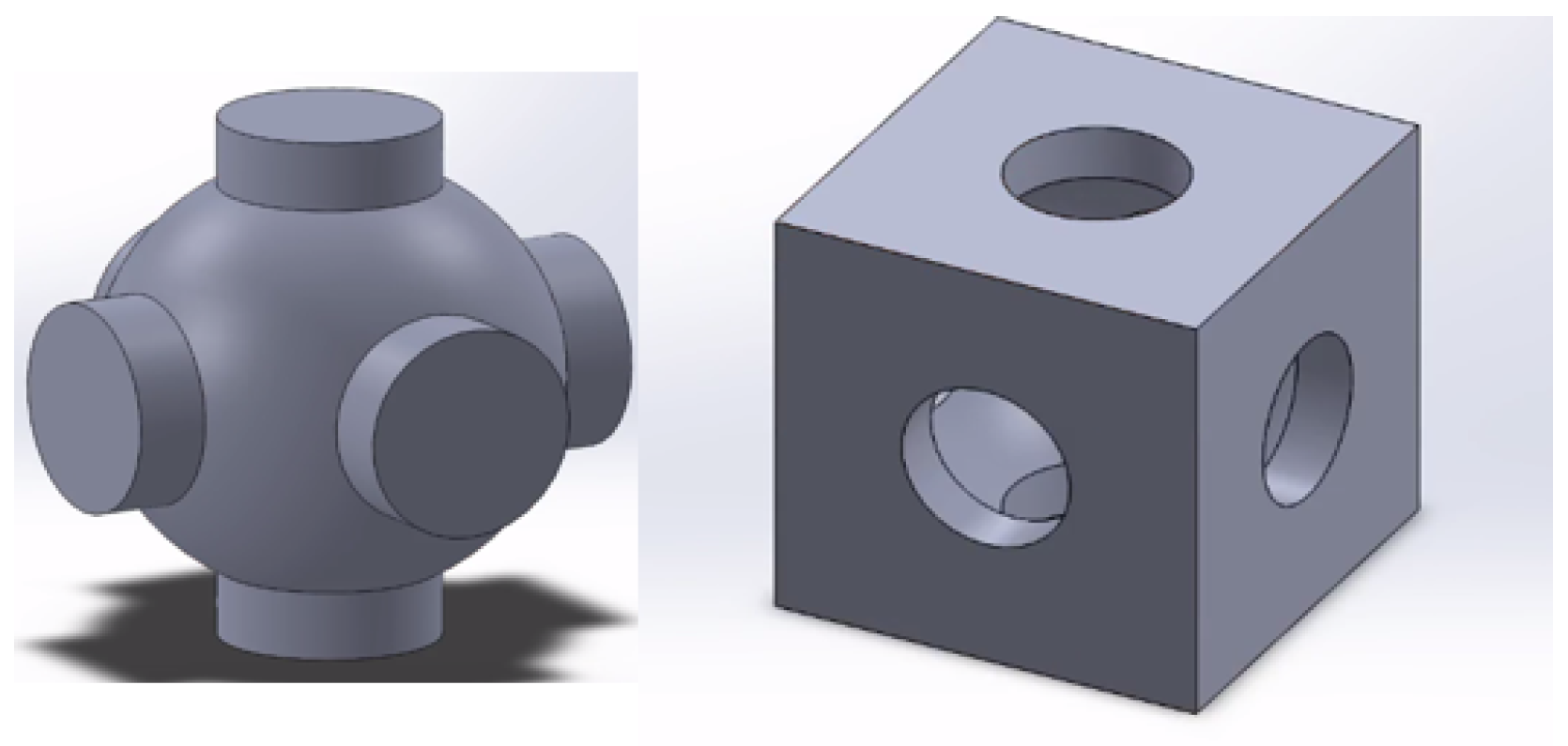
35]. The performance of this design in a grazing incidence configuration as found in a silencer has not previously been investigated. This material consists of a periodic unit cell structure of cubes with spherical internal cavities connected through cylindrical openings on each face of the cube [
14].
The cavity design and unit cell shown in
Figure 2 is the benchmark DENORMS design. It can be easily incorporated into acoustic metamaterial cylinders due to the simple shape and internal geometry. The benchmark unit cell is 5mm in length, width and height, and includes a 4.2 mm diameter spherical cavity. The silencer cylinder sizing should be evenly divisible by the unit cell size in all dimensions.
Each unit cell within a metamaterial acts as an individual resonator, and when these resonators are connected, the sound attenuation properties of the material change. The propagation of sound waves through the material is hindered, thereby achieving a sound absorption [
23].
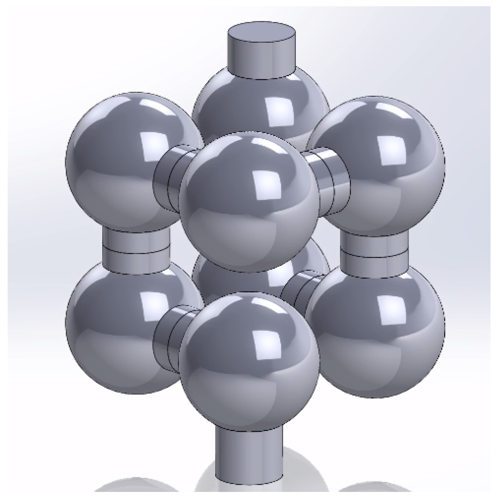
The sound absorption is frequency dependant. The operational frequency of a DENORMS material is dependant on the number of cells in the chain. As previously discussed, the lower limit of the two-load test rig is 300 Hz and the upper limit is 4800 Hz, therefore the metamaterial design must lie within this range to accurately capture the effectiveness within the silencer. To achieve this, a labyrinthine DENORMS design was implemented. A labyrinthine structure increases the length of the chain of unit cells for a given thickness by altering the number and position of the openings of the unit cell, the design of this structure is shown in
Figure 3.
The acoustic metamaterials were created using Fused Deposition Modelling (FDM) 3D printing on a Prusa mini machine and the material used was polylactic acid (PLA). It is noted that this material would not be suitable to withstand the high thermal impact, chemical corrosion and vibrations within a real automobile exhaust system. As this is a representative silencer it will not be connected to an engine and therefore won’t need to be created to withstand the temperature and chemicals produced by an engine. The materials often used in a silencer are stainless steel or mild steel and can be coated in an aluminium alloy for further corrosion resistance. The DENORMS baffles and cylinders have previously been manufactured in stainless steel using selective laser melting (SLM) which may be suitable for use in the automotive industry [
14,
35]. The behavior of the DENORMS design does not depend on the material properties and only on the geometry of the interior air cavities. For this reason the acoustic behavior is independent of additive manufacturing technique apart from the impact of geometric accuracy and surface roughness which vary between processes and machines.
This labyrinthine design is suitable for implementation into the internal cylinders. The performance will be evaluated analytically and experimentally to determine if acoustic metamaterials can be used to attenuate sound in an automotive silencer.
3. Analytical Model
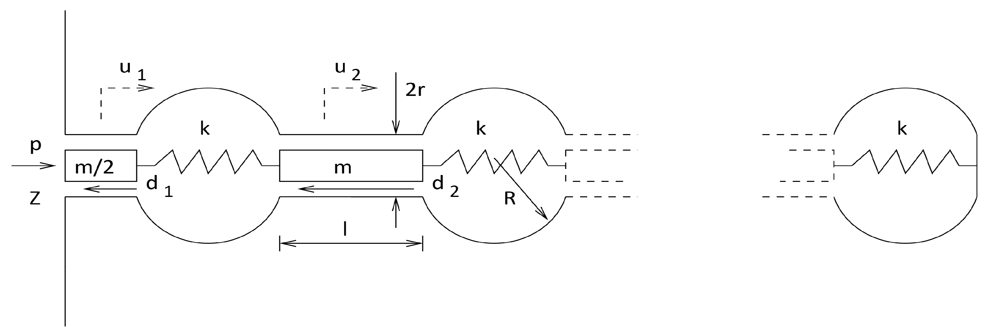
The acoustic labyrinthine structure described above and embedded in the cylinder walls can be modelled as a series of interconnected Helmholtz resonators as shown in
Figure 4. The inertial elements with mass
m and viscous losses modelled by the drag
d are assumed to be confined to the interconnecting cylindrical elements with length
l and radius
r whilst adiabatic dilatation is assumed to occur in the spherical elements of radius
R. The volumetric compressibilty within these is dynamically modelled as interconnecting springs of stiffness
k. Thus the entire system may be modelled as a coupled spring mass damped system driven by the external pressure
p with each mass element having a notional velocity
. Note that the length of the first cylinder is halved.
The effective silencer inner wall frequency dependent impedance for the cylinder will be:
where
is the velocity of the first inertial element and where the porosity
is given by:
where
is the (rectangular) surface spacing between the pores. The connecting (stiffness) elements
k in the structure are given following eg Dowling et al. [
36] by
where
c is the sonic speed,
is the air density, and
is the circular frequency. This will be valid as the wavelengths under consideration are much longer than the dimension
R of the chambers.
The inertial elements are given by:
To estimate the drag forces
d we follow Allard and Atalla [
37] who provided a model for a frequency dependant flow resistivity
per unit length in a cylindrical tube of radius
r as
where
s is given by:
Here,
is the dynamic viscosity and
is a correction for surface roughness. Based on increased hydraulic radius from optical observations of the surface profile in this study this was set at 1.2. Additionally there is a Rayleigh resistance associated with spreading on the surface of an infinite half plane [
37]. This is given by:
The total loss force on a mass element
i is therefore:
Again, following [
37] the effective length of the cylinder is lengthened to model acoustic action external to the ends of the ducts.
In the case of the first node the loss force changes to:
on account of the shorter duct length
.
A dynamical system may now be established in the form:
where
M is diagonal with elements
,
C which is frequency dependent is also diagonal with elements
and the stiffness matrix
is tri-diagonal of the form
The subdiagonal zero term on the last row above implements the fixed boundary condition at the end of the labyrinthine sequence.
The forcing vector is of the form .
The complete system
13 may now be solved for
and the (frequency dependent) wall impedance
Z was determined using Equation (
4).
The absorptivity
a then follows from:
4. Performance Validation
The accuracy of the analytical model was initially established through the measurement of a sample under normal incidence. The labyrinthine structure shown in
Figure 3 was incorporated into a cylindrical impedance tube sample. The labyrinthine metamaterial sample shown in
Figure 5 was printed and then tested according to ISO 10534-2 using the same experimental rig as the silencer but reconfigured into an absorption measurement setup,
Figure 1.
The absorption coefficient from the experimental normal incidence test was compared with the analytical model.
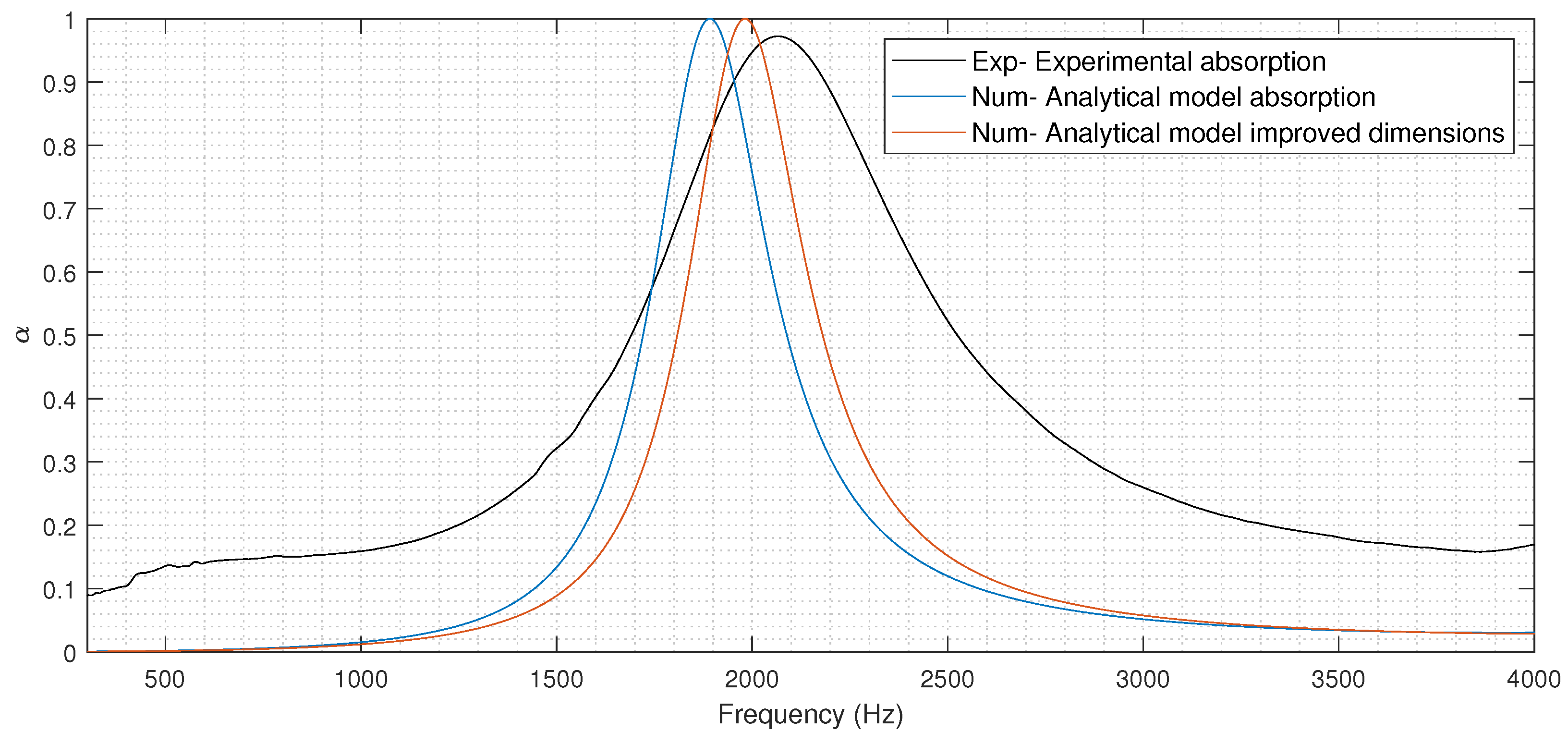
From
Figure 6, it can be seen that the frequency peak for the analytical model and the experimental results for the normal incidence do not correspond. Using the designed dimensions, the analytical model predicts the behavior of the DENORMS labyrinthine design to operate at a lower frequency than that of the actual experimental values. To improve the accuracy, the input parameters of the analytical model can be altered. The tolerance of the machine used to print the metamaterial structure was investigated. A section through the DENORMS cylinder was printed and the exact internal geometries of the DENORMS labyrinthine structure were established. The diameter of the internal spherical cavities is reduced slightly in the additively manufactured parts. These new internal dimensions were inputted into the analytical model with improved results. The higher broadband absorption of the experimental results is likely due to the high surface roughness of the additively manufactured parts [
14,
38]. The agreement with the analytical model under normal incidence is sufficient to be used as an input for the subsequent modelling step which will involve an iterative fit with experimental data under grazing incidence.
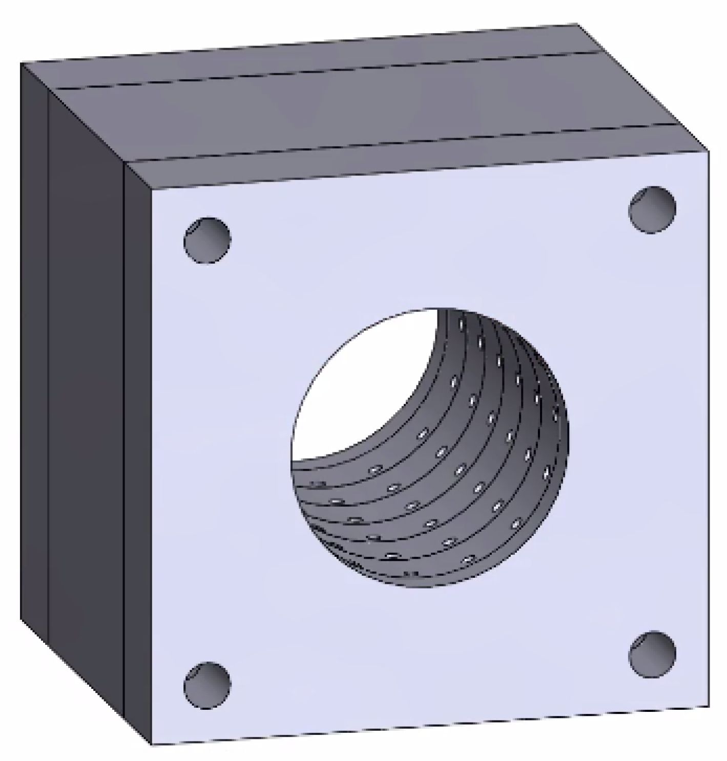
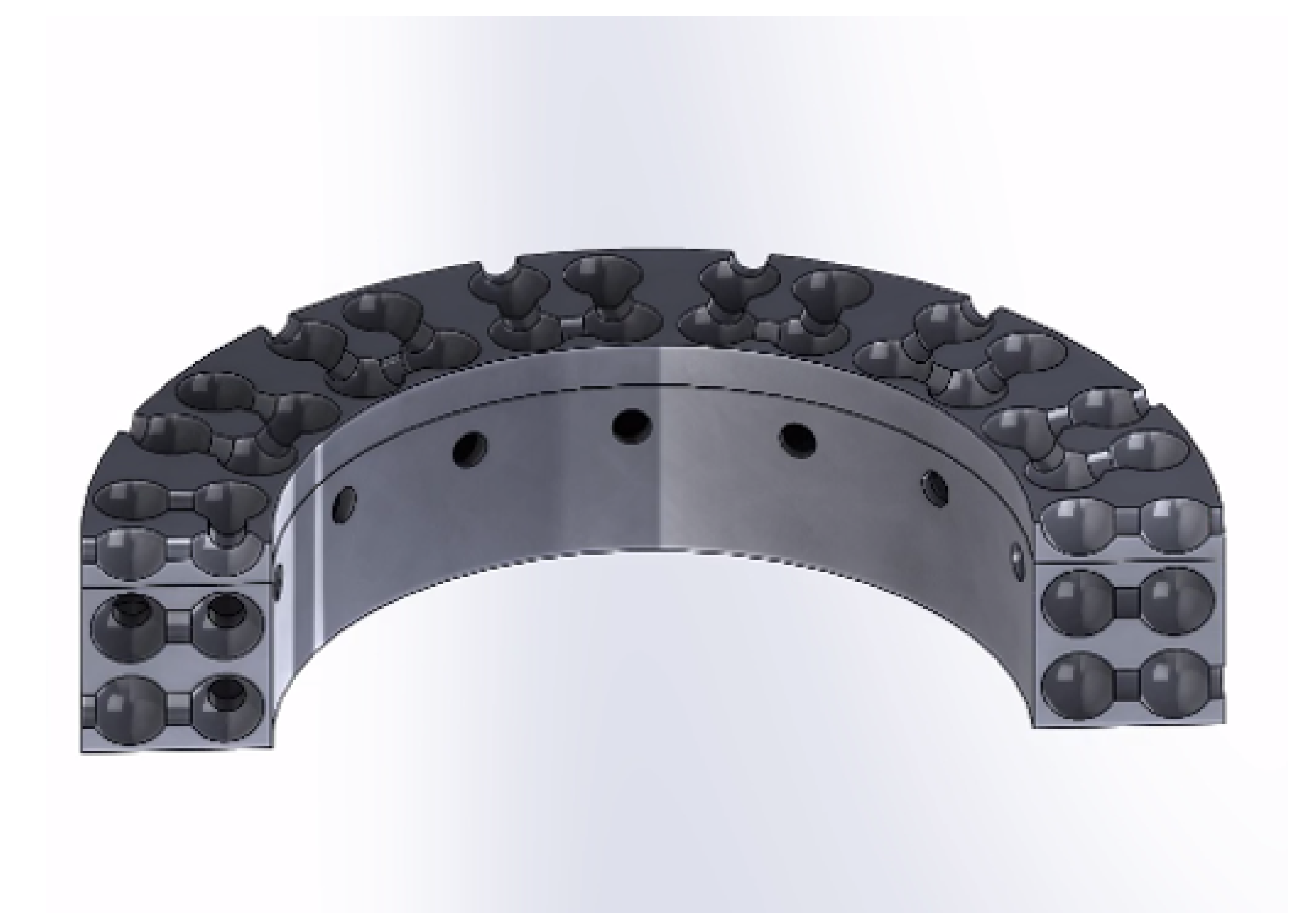
The sound waves interact with the DENORMS cylinder within the automotive silencer under grazing incidence. The accuracy of the analytically predicted impedance needs to be validated under grazing incidence. The DENORMS labyrinthine cavity block was set up shown in
Figure 7, a cross section of this design is shown in
Figure 8. This sample was manufactured using FDM printing and tested in the transmission loss test rig.
The analytical model obtains the real and imaginary impedance of the acoustic metamaterial structure. These results are implemented as a boundary condition in the COMSOL simulations to allow the comparison of the experimental and analytical results for performance validation of the metamaterial cylinder, as shown in
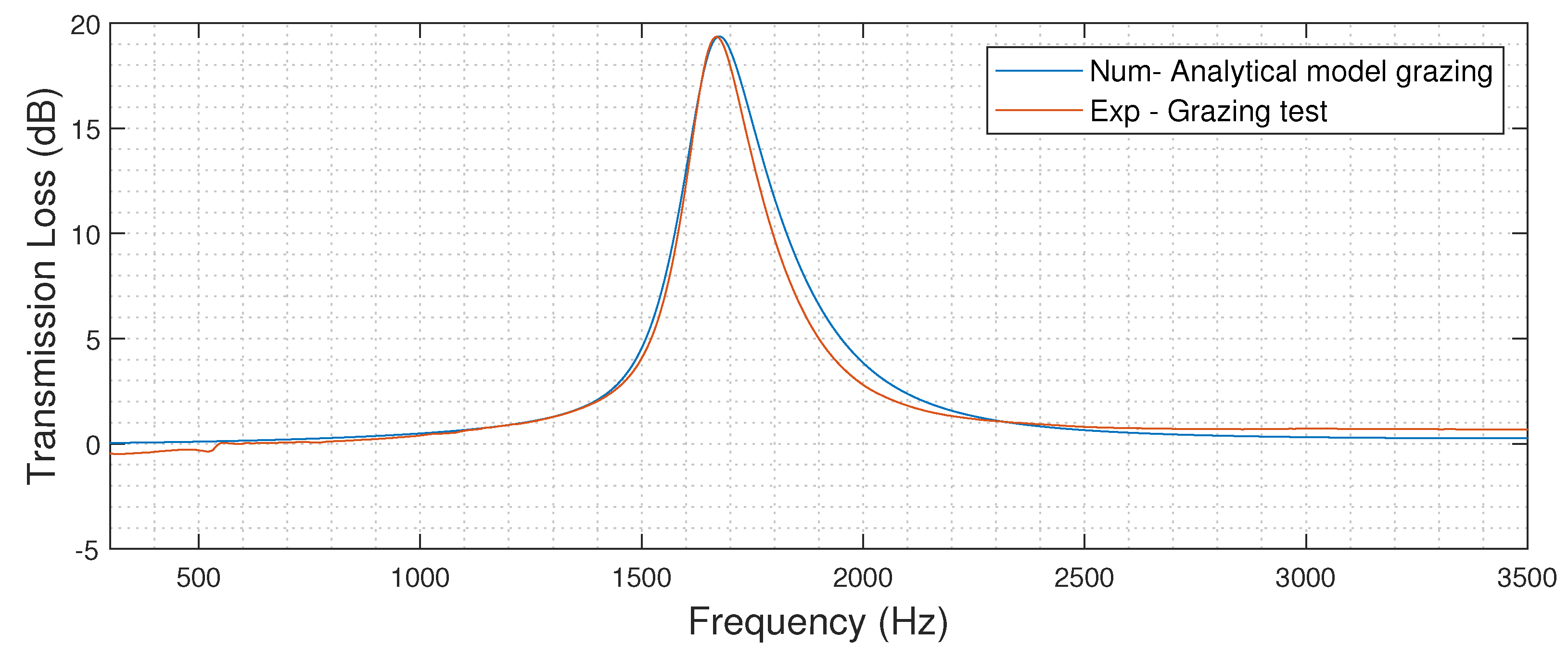
Figure 9. Initial results over estimated the frequency at which the metamaterial operated. An iterative fitting procedure was implemented to adjust the internal dimensions of the metamaterial, within manufacturing tolerances, until a match was achieved with experimental results. This fitting procedure also has the possibility of correcting for any change from normal incidence to grazing incidence in the model. The results of the experimental and numerical comparison following the fitting procedure are shown in
Figure 10. This surface impedance boundary condition can now be used within the modelling of the automotive silencer to represent the acoustic metamaterial without the need for detailed sub-surface modelling.
6. Experimental Silencer Performance
In order to match the COMSOL simulation resolution of 5Hz, the experimental sample rate was set to 40,000 Hz with an FFT block length of 8192 giving a resolution of 4.88 Hz. Tests are carried out with a duration of 240 seconds for each load, which achieves a minimum of 2000 averages in the transfer function estimations.
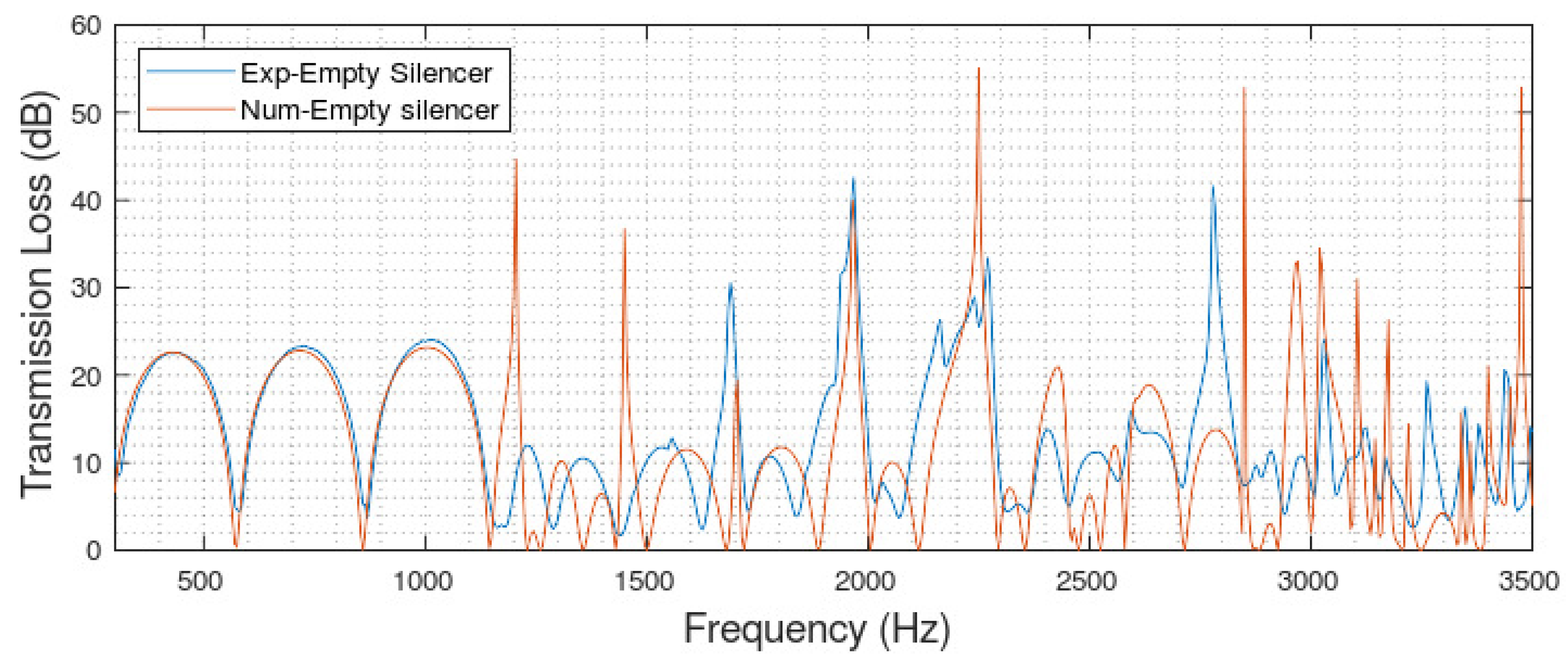
Results for transmission loss versus frequency are presented in narrowband or octave band plots, with an increase in the transmission loss representing an increase in silencer performance. The performance of the experimental baseline silencer configuration was validated using COMSOL simulations. The results shown in
Figure 11 demonstrate satisfactory agreement between the numerical and experimental performance of the silencer. This demonstrates that the COMSOL model created for the empty silencer is an accurate representation of the real-world performance. Furthermore, the two-load test rig method used to experimentally evaluate the silencer performance is shown to be suitable for use in this application.
The experimental silencer has dampening associated with the type of material used. This dampening reduces the peak of the transmission loss and increases the width of the resonance peak. The numerical results assume a lossless system with acoustically hard walls, which cannot be replicated precisely in the physical set up. Slight differences are to be expected and the good match, considering the expected differences, between the experimental and numerical data for the tested configurations demonstrates that both the COMSOL and the experimental set up are accurate and representative.
The uncertainty in the experimental test rig was evaluated through a series of repeat measurements. Three tests were conducted for the most basic internal geometry and the results are shown in
Figure 12.
To ensure that the tests were accurately capturing the error, the silencer was tested on different days with different microphone calibrations. Furthermore, the silencer was completely disassembled and reassembled before each test. The standard deviation between the three experimental results was calculated for every frequency point result. The mean standard deviation across the entire frequency range for the most basic internal setup was found to be 1.2 dB.
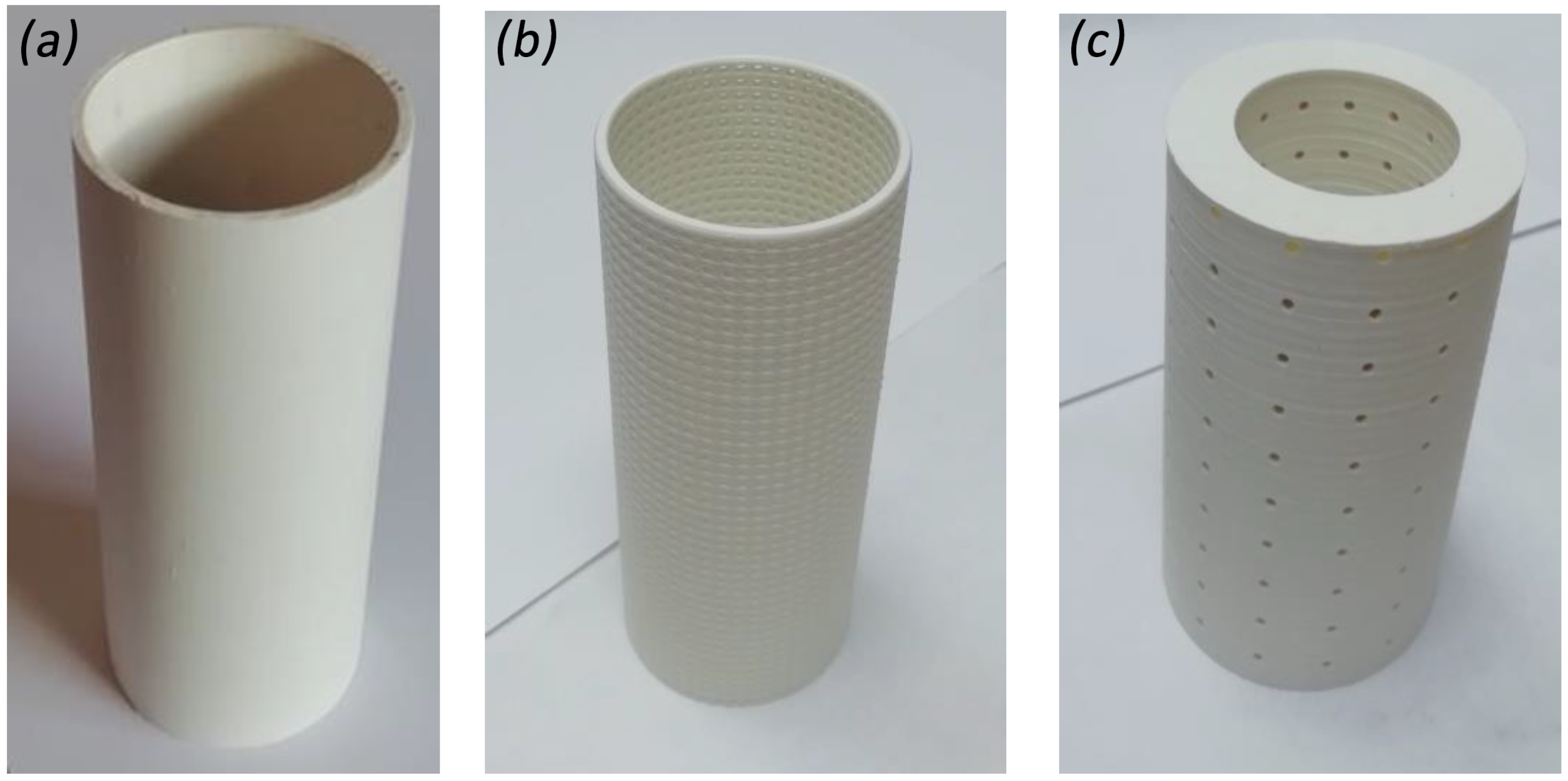
A labyrinthine DENORMS cylinder was designed and printed, shown in
Figure 13, to establish if performance could be enhanced with the use of acoustic metamaterials. The metamaterial cylinder was experimentally compared to a silencer with no cylinders, hard cylinders and perforated cylinders also shown in
Figure 13.
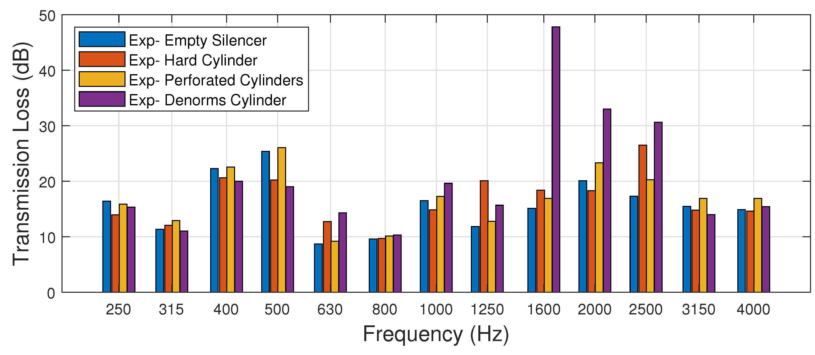
The experimental results are shown in
Figure 14. All of the tested cylinder types behave similarly between 0 and 1000 Hz. The metamaterial cylinder has a transmission loss spike between 1600 and 2500 Hz. It provides an improved transmission loss value of 40 dB when compared to the other internal cylinder types. This metamaterial cylinder consists of a labyrinthine chain of 8-unit cell layers and corresponds to the anticipated frequency range for increased performance.
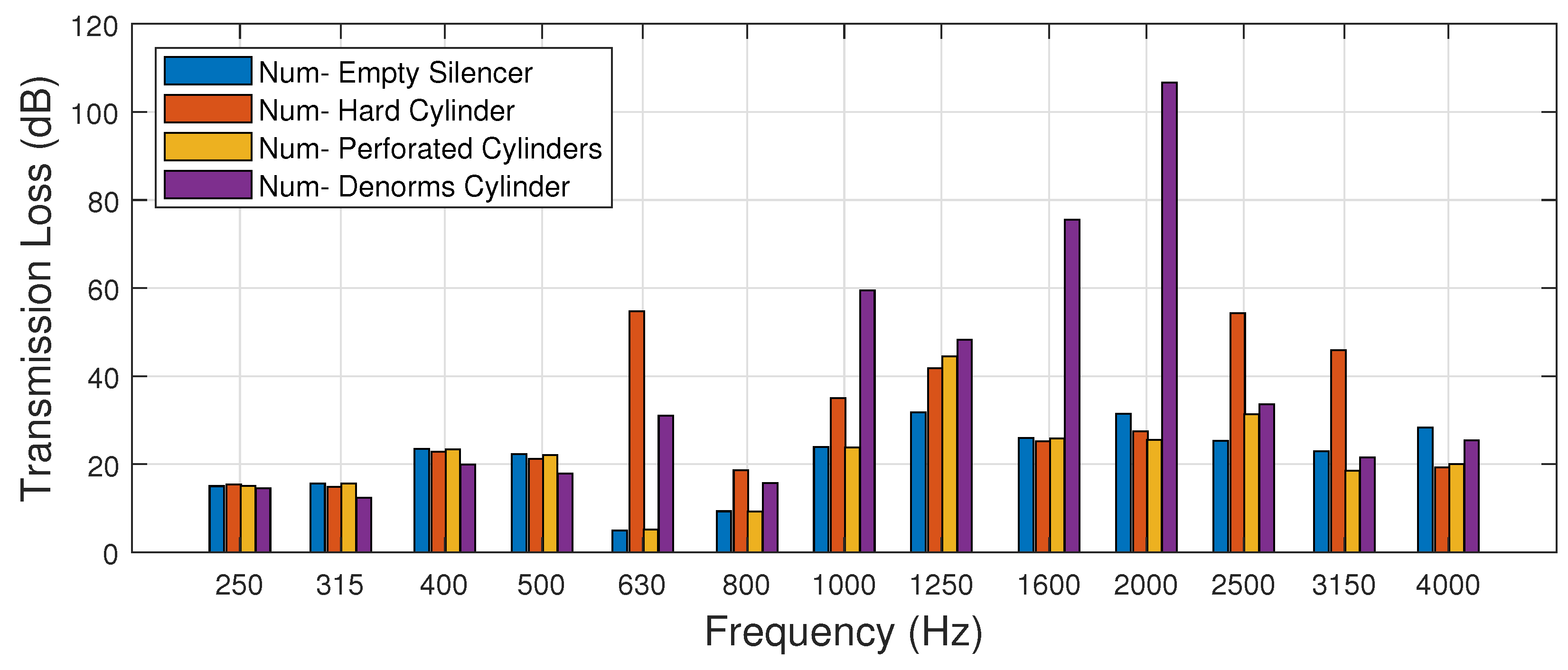
The numerical results are shown in
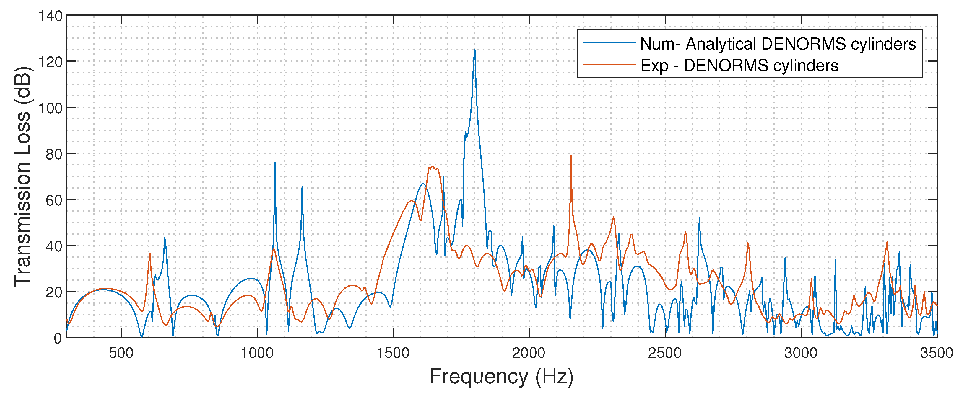
Figure 15. Excellent agreement is observed with the experimental results in terms of the frequency range of the performance increase. The numerical model predicts an increase in performance above what can be experimentally tested. The signal to noise ratio of the experimental tests limits measurements to an 80 dB transmission loss. Therefore the numerically predicted values are greater than what can be measured experimentally. This is more clearly visible in
Figure 16 where experimental values are limited to 80 dB and numerical values exceed 120 dB. A 120 dB reduction cannot be validated experimentally and so it remains possible that the silencer does achieve this reduction in practice, an 80 dB drop is significantly above current commercial silencer design criteria [
2]. Deviations in frequency location could be attributed to the difficulty of achieving an accurate representation of the geometry of the 3D printed parts. The influence of the additive manufacturing layer height on the location of the absorptive peak is currently unknown. Increased manufacturing layer heights lead to a higher surface roughness and a systematic change to the geometry, the impact of which needs to be assessed and incorporated in the model in future work.
The DENORMS labyrinthine cylinders have been demonstrated to improve the performance of the silencer when compared with the traditional perforated and hard walled cylinders. There is satisfactory agreement when considering the very low computational cost of the modelling between the numerical and experimental results for the representative silencer, with the numerical model potentially overestimating the increase in performance.
