
Comprehensive Methodology for Quality Assurance Following Installation and Backfilling of Polymer-Coated Steel Pipelines



Highlights
- Establishing the new criteria for 3LPE coating of underground steel pipelines, including re-definition of defect severity classification, and stricter minimum performance thresholds for oil/gas and water pipelines.
- First systematic QA framework for post-installation/backfilling assessment of polymer coatings.
- Introduction of quantitative criteria for average specific electrical resistance of polymer coatings.
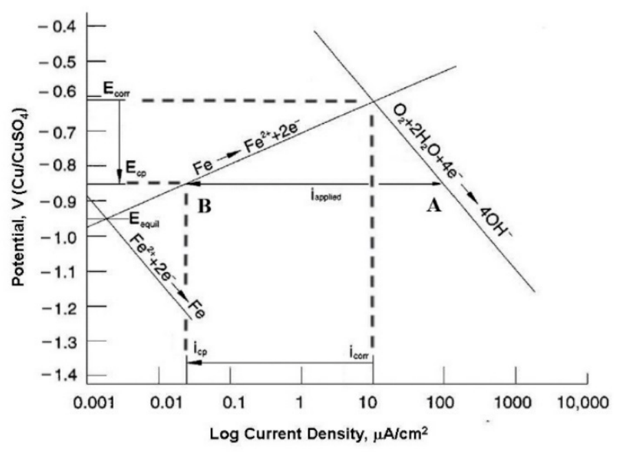
- Direct correlation between coating defects, dielectric degradation, and cathodic protection (CP) current demand.
- Introduction of a physically based new parameter: specific coating defect ratio (Ae).
- Integration of complementary NDT methods into a unified polymer coating QA protocol.
- Enhanced coating reliability and service life through early post-installation QA, enabling detection of installation-induced defects and control of corrosion protection performance from initial service stages.
- Optimized inspection strategy through integration of DT (Drainage Test) and DCVG (Direct Current Voltage Gradient) results into a unified polymer coating QA protocol, enabling efficient staged diagnostics and reducing unnecessary excavations.
- Defect-controlled integrity management linking defect density (Ae), electrical resistance, and CP current, enabling predictive maintenance focused on localized damage rather than bulk polymer degradation.
- Transition from qualitative to quantitative QA through resistance-based criteria and defect metrics, enabling standards revision aligned with the dielectric performance of modern 3LPE coatings.
Abstract
1. Introduction
- North American regulation, like [38], requires the utilization of non-shielding coatings for buried pipelines. A non-shielding coating allows cathodic protection current to reach the pipeline surface even if the coating is disbonded. Disbondment is the loss of adhesion and separation of a protective polymer coating from the underlying steel substrate [39]. Therefore, the prevalent external pipeline coating in the USA is Fusion Bonded Epoxy (FBE) with the above required characteristics according to international standards [40,41,42].
- In Europe and the Middle East, pipelines are typically protected from corrosion using a three-layer extruded polyethylene (3LPE) coating system combined with Impressed Current Cathodic Protection (ICCP). This combination has been proven highly effective over time. This type of coating constitutes a shielding coating that prevents cathodic protection (CP) current from reaching the pipeline surface [43].
2. The Polymer Coating’s Specific Electrical Resistance
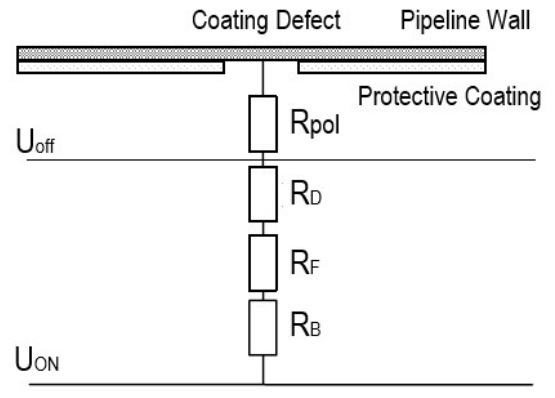
- Rpol—polarization resistance in coating defect (Ω).
- ΔU—polarization shift in defect potential (0.3 ÷ 0.6 V)
- ΔU = Uoff − Un (Uoff—Instant Off potential, V (without current); Un—natural potential, V)
- j—current density of polarized defect (0.1–0.5 A/m2)
- AD—Defect area (m2)
- rpol—specific polarization resistance (Ω·m2); rp = 0.3V/0.3A·m−2~1 Ω·m2
- RD—resistance of the polarization film (Ω).
- rD—Average electrical resistance of the defect’s coating layer formed on the surface of cathodically protected steel (Ω·m2); rp = 1 ÷ 10 Ω·m2 (rp(average) ≈ 5 Ω·m2).
- AD—Defect area (m2).
- RF—The longitudinal resistance in the fault location (Ω).
- ρ—Specific electrical soil resistivity (Ω·m).
- l—coating thickness (m).
- AD—Defect area (m2).
- RB—Resistance to defect current spreading through the soil/The resistance to remote earth (Ω).
- ρ—Specific electrical soil resistivity (Ω·m).
- d—equivalent diameter of surface (m).
3. Coatings Defects in Conjunction with Cathodic Protection
- a.
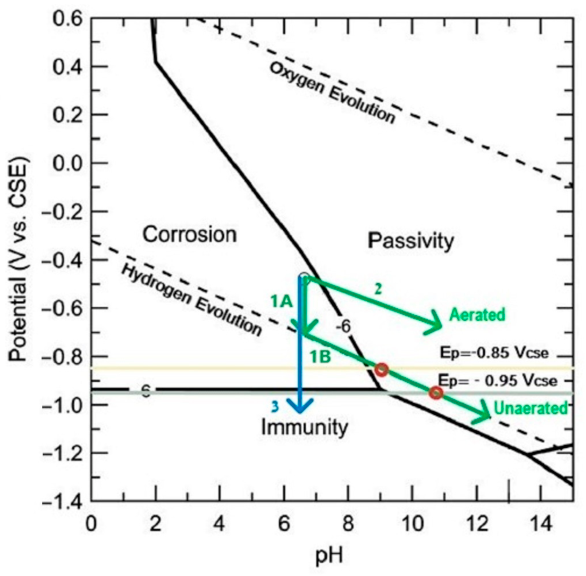
- Protective potentials criteria of −0.85 VCSE and −0.95 VCSE—both, the increased oxygen reduction (lower concentration of oxygen dissolved in the electrolyte) and the hydrogen evolution
- ○
- At −0.85 VCSE (IR-free potential), the steel surface reaches a pH of 9, a level that ensures passive film formation in normal and aerobic soil conditions.
- ○
- At −0.95 VCSE (IR-free potential), the steel surface reaches a pH of 10.5, a level that supports passivity in anaerobic and aggressive soils.
- b.
- Protective potentials criteria of −0.65 VCSE and −0.75 VCSE—Overpotential oxygen reduction
- c.
- Poor bedding or presence of SRB (Sulfate Reducing Bacteria)
4. The Current Comparison Method
- -
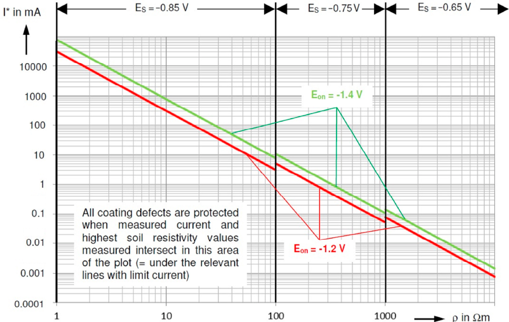
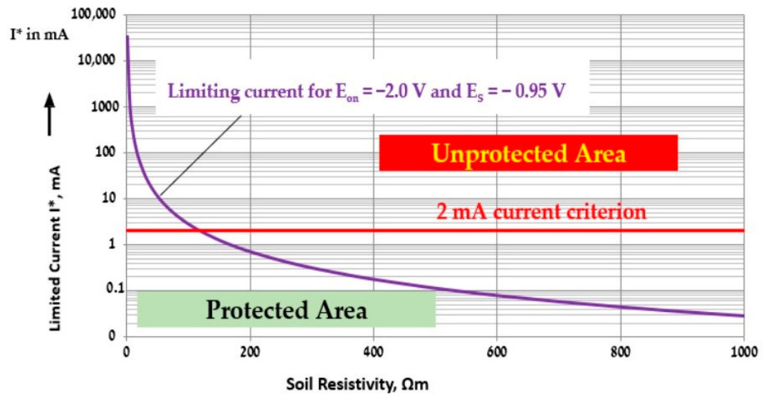
- Calculation (based on a worst-case quality) of the limiting current I* value needed to achieve a protection potential or IR-Free potential (Es).
- -
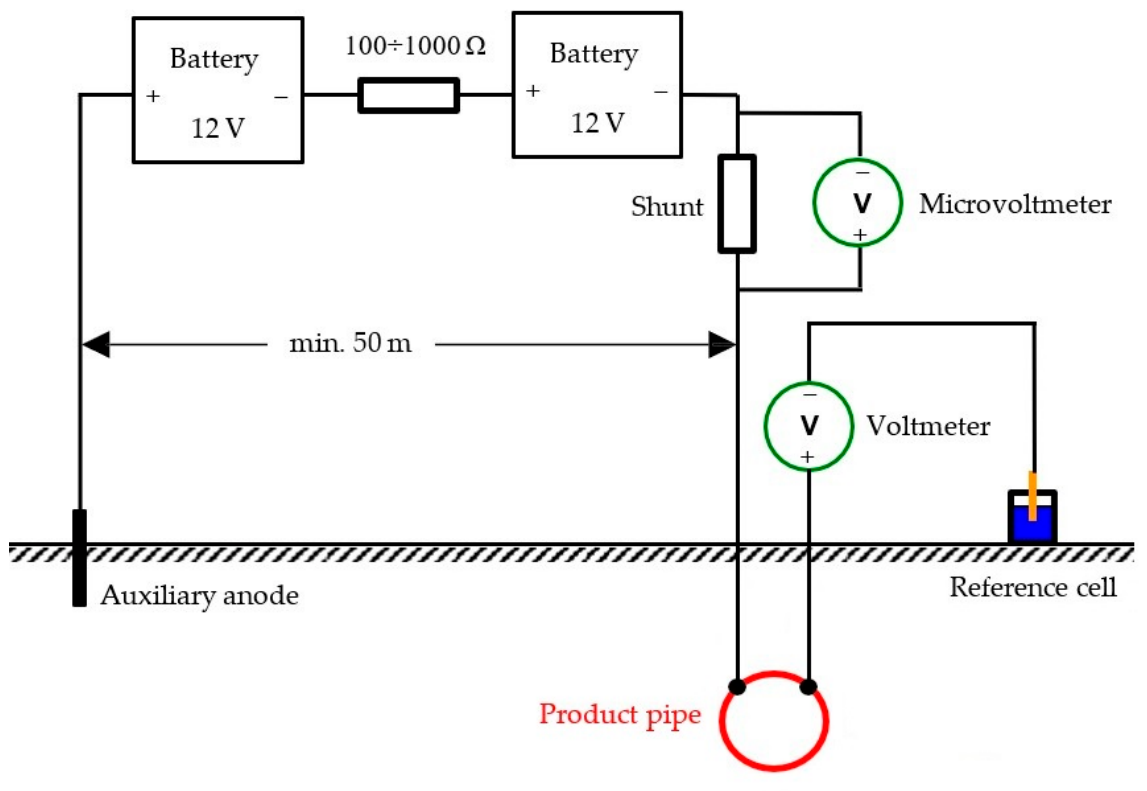
- Performing a Drainage Test (cathodic polarization) to measure the actual polarization current I.
- -
- Calculation of the I* value compared with the actual measured I value to evaluate whether the pipeline is protected against corrosion.
- ΔE—IR drop in soil caused by the current running to a coating defect
- Eon—Potential of coating defect (i.e., pipeline) as measured in remote earth
- EIR-free—Potential at the coating defect
- I—Protection current (A).
- ΔE—IR drop in soil caused by the current flowing to a coating defect, V (ΔE = Eon − EIR-free).
- J—Current density (A/m2).
- ρ—specific soil resistivity (Ω·m).

| Medium | Protection Current Density in mA/m2 |
|---|---|
| Soils with sand and gravel | 500 |
| Mixed soil | 200 |
| Cohesive soils of clay | 100 |
| Standing groundwater | 100 |
| Flowing groundwater (for example on slopes) | 200 |
5. Criteria for Protection Potentials
- -
- The Off potential measured at the drain point must fulfill the protection potential ES.
- -
- The intersection points of the measured polarization current and the highest soil resistivity measured along the pipeline must be located below the relevant line with limit current, as shown in Figure 2.
6. Experimental Procedure
6.1. General
6.2. Determination of Coating Average Specific Electrical Resistance and Consumed Electrical Current Criteria in Newly Installed and Backfilled Buried Pipes
- The Drainage Test (Cathodic Polarization) Procedure
- The auxiliary anode must be installed at a distance of at least 50 m from the pipeline under investigation.
- The spreading resistance of the anode must be low enough to achieve an On potential of 24 V at the pipeline (usually up to 5 Ω).
- The Voltmeter for the potential measurement should have an internal resistance Ri ≥ 10 MΩ. Furthermore, the voltmeter must be disconnected when the current is measured.
6.3. Indirect Above-Ground Methods for Identifying Coating Defects
- OL/RE—potential difference from the indication epicenter to remote earth (mV).
- P/RE—Pipe to remote earth signal magnitude (mV).
7. Results
- The steel grade for pipes is X42, with a typical length of 12.2 m and varying wall thicknesses
- The factory-applied external coating: 3-layer extruded HDPE (3LPE) with varying coating thicknesses according to the standard [24]:
- ○
- For oil/gas pipelines—the top layer was stabilized (antioxidant-containing) HDPE;
- ○
- For water pipelines—the top layer was unstabilized (antioxidant-free) HDPE;
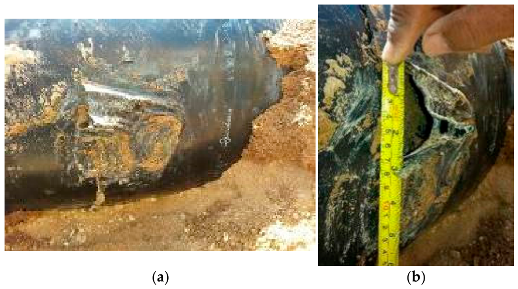
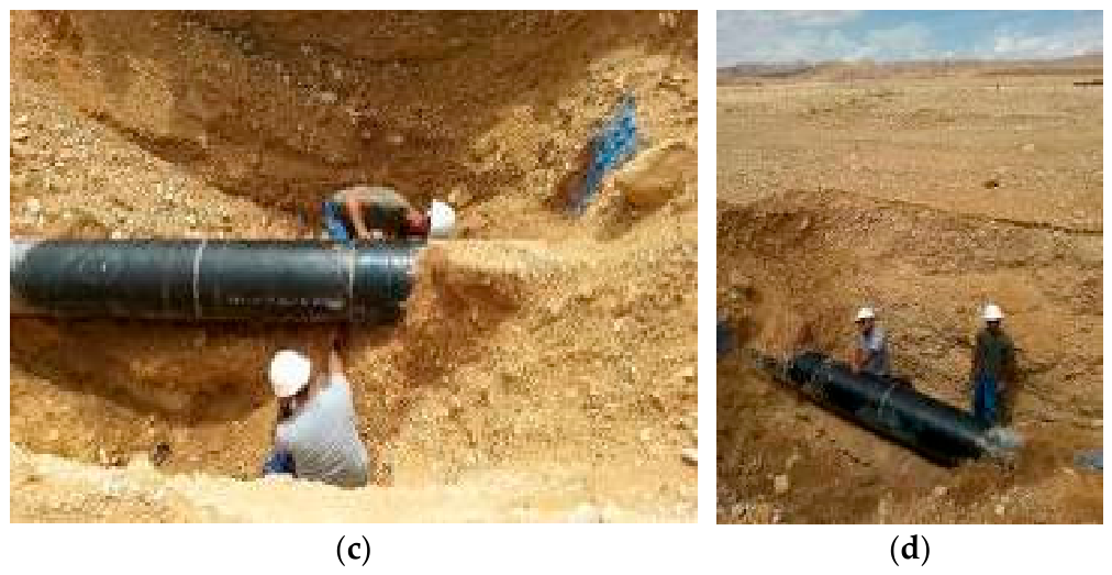
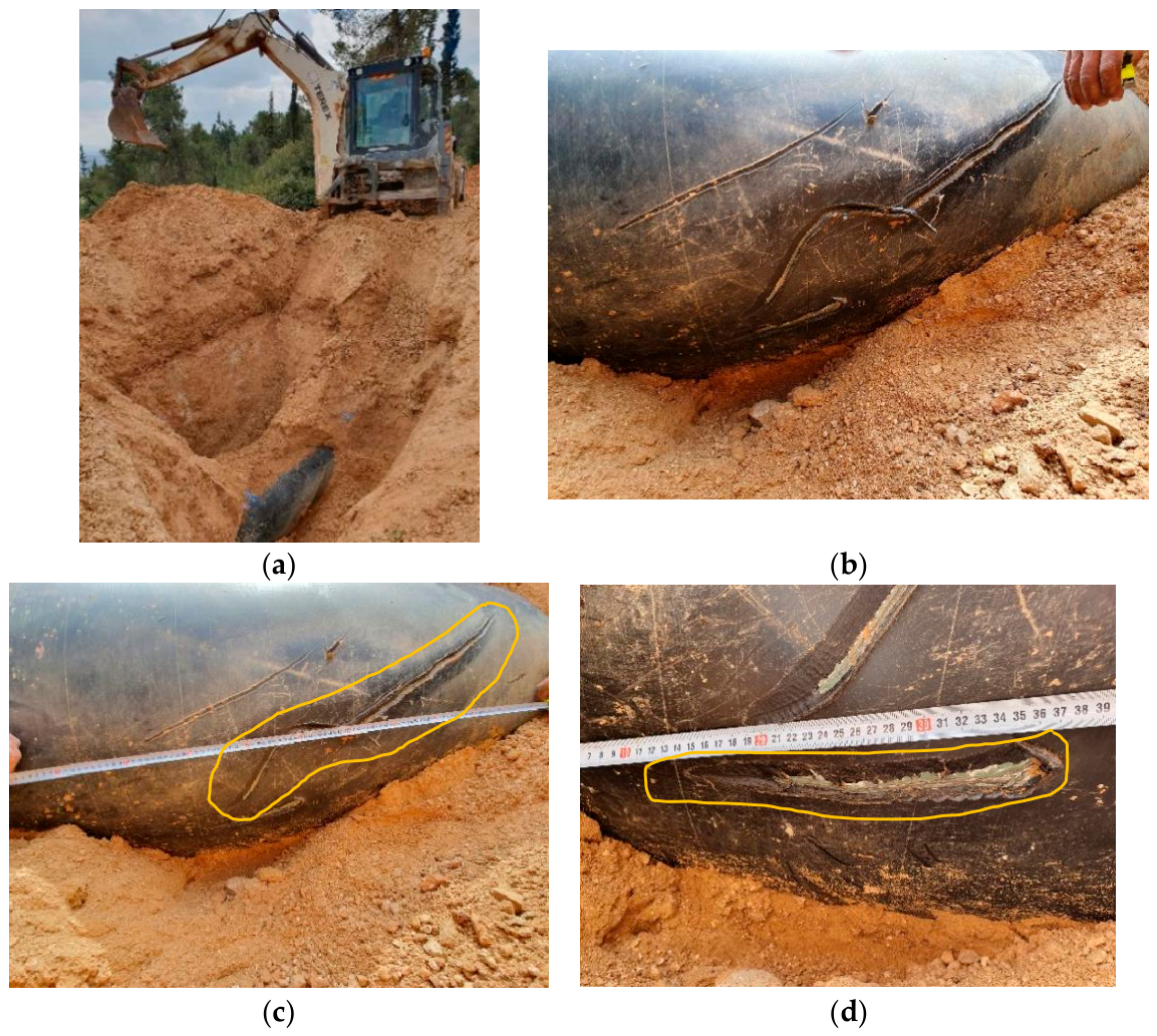
The Last Stage: Direct Examination
8. Discussion
- a.
- Coating Thickness Decrease (Uniform Wear/Thinning)
- Sensitivity: Our method is not sensitive to the decrease in the coating thickness.
- Mechanism: Direct Current Voltage Gradient (DCVG) and Drainage Tests rely entirely on the flow of electric current through a holiday (defect/hole) from the soil to the steel surface. As long as the 3LPE polymer coating remains continuous, even if its thickness is significantly reduced due to mechanical scraping or soil stress, the electrical resistance remains extremely high.
- Implication: Thinning without a physical puncture will not trigger a voltage gradient or an increase in current demand. Therefore, these methods cannot map gradual thickness degradation.
- b.
- Size of Cracks and Holidays (Through-Thickness Defects)
- Sensitivity: Extremely High. The experienced DCVG operator detects very small polymer coating flaws (holidays) exposing up to 1 cm2 of the steel substrate at a trench depth of 2 m, under high resistivity backfill soil conditions (>100 Ω·m). In highly resistant soil conditions (>100 Ω·m), it is recommended to wet the contact areas around the reference electrodes for optimizing electrolytic coupling, thereby enhancing the sensitivity required to detect structural anomalies and flaws within the dielectric polymer insulation during DCVG surveys.
- Mechanism: When a crack or puncture penetrates the full thickness of the polymer coating to achieve the bare steel, an electrical path is established. The sensitivity of the DCVG method is quantified by calculating the defect severity (%IR).
- c.
- Precision of Localized Corrosion Areas for Excavation
- Spatial Precision: The methodology demonstrates a high pinpoint precision up to ±0.5 m along the pipeline axis.
- Epicenter Determination: By utilizing the DCVG reference electrodes in a “null” balance or peak-signal configuration directly over the centerline of the pipe, operators can identify the exact epicenter (zero-point) where the current vectors converge.
- Directional Resolution: The method not only finds the longitudinal location but can often indicate whether the defect is on the top, side, or bottom of the pipe based on the symmetry of the voltage gradient fields mapped on the ground surface.
- 207 defects (94%) are identified with a relative size %IR ≤ 15 and considered as nonsignificant defects. They are distributed as follows: very small (0 < %IR ≤ 1)—127 defects (58%), small (1 < %IR ≤3)—58 faults (26%), moderate (3 < %IR ≤ 15)—22 defects (10%).
- Other 13 defects (6%) with relative sizes of %IR > 15 are considered as significant faults and are distributed as follows: medium (15 < %IR ≤ 35)—7, significant (35 < %IR ≤ 60)—3, critical (%IR > 60)—3.
- The above distribution of defects across different relative sizes varies from the definitions found in the two versions of the standard [9] from 2002 and from 2008. These versions of the standard are more applicable to previous coating generations with an equal distribution of defects, such as coal tar, bitumen, cold tapes, and even FBE. In the latest version of the standard (2010), the categories of fault distributions have been abolished.
- The different benchmark classification of %IR distribution has been proposed in this study for 3LPE coating with unequal distribution of defects: small (0 < %IR ≤ 1); moderate (1 < %IR ≤ 3) and significant (%IR > 3).
9. Conclusions
- First systematic quality assurance (QA) framework for post-installation/backfilling coating assessment
- Introduction of quantitative criteria for average specific coating electrical resistance
- Proposal for a new physically meaningful parameter: specific coating defect ratio (AE)
- Integration of complementary NDT methods into a unified QA protocol
- Re-definition of defect severity classification for modern 3LPE coatings
- Small defects (%IR < 1%). Typically correspond to small punctures, scratches, or narrow cracks. The methodology classifies these as low priority, often requiring only continuous monitoring rather than immediate excavation, as the cathodic protection (CP) system can easily mitigate corrosion at these discontinuities.
- Medium (1 ≤ %IR < 3%) and large defects (%IR ≥ 3). Correspond to moderate and severe mechanical damage, wide cracks, or large chunks of missing coating. These create moderate and large voltage gradients in the soil, making them highly visible to the DCVG operator.
- Establishment of stricter, application-specific performance criteria for HDPE-based coatings
- Direct linkage between coating defects, dielectric degradation, and CP current demand
Author Contributions
Funding
Data Availability Statement
Acknowledgments
Conflicts of Interest
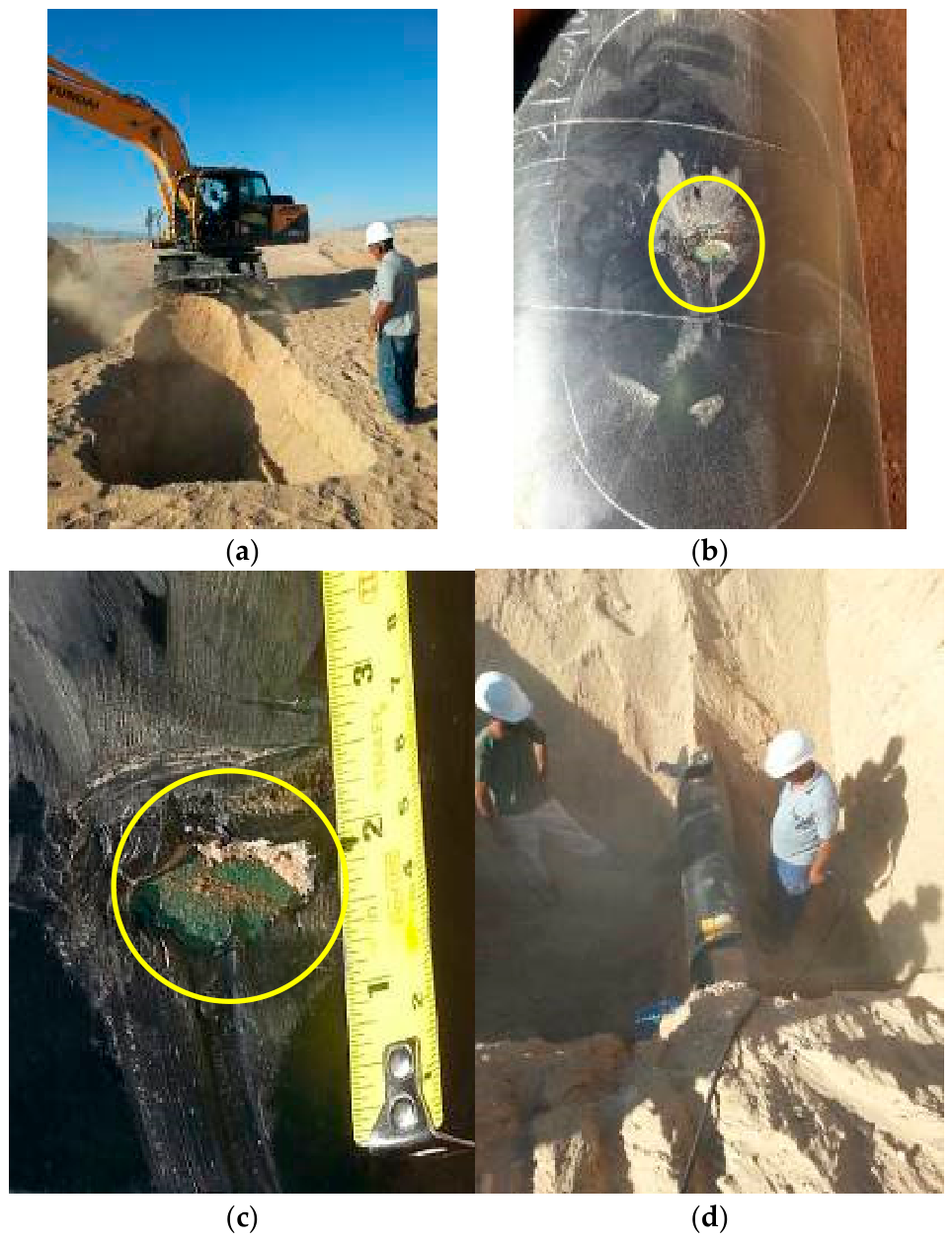
Appendix A. The Typical Examples of Various Defects and Their Severity Identified by DCVG Indirect ECDA Method


References
- Corrosion Cost and Preventive Strategies in the United States; Publication/Report Number: FHWA-RD-01-156, R315-01; Federal Highway Administration: Washington, DC, USA, 2001. Available online: https://rosap.ntl.bts.gov/view/dot/40697/dot_40697_DS1.pdf (accessed on 16 March 2026).
- Roberge, P.R. Corrosion Engineering: Principles and Practice, 1st ed.; McGraw-Hill Education: New York, NY, USA, 2008. [Google Scholar]
- API RP572-2016; Inspection Practices for Pressure Vessels, 4th Edition. The American Petroleum Institute (API): Washington, DC, USA, 2016.
- Liu, Z.; Kleiner, Y.; Rajani, B. Condition Assessment Technologies for Water Transmission and Distribution Systems; EPA600R-12017; U.S. Environmental Protection Agency: Washington, DC, USA, 2012.
- Rajani, B.; Kleiner, Y.; Rajani, B.; Kleiner, Y. Selecting Cost-Effective Condition Assessment Technologies for High-Consequence Water Mains; Project #4553; Water Research Foundation: Denver, CO, USA; AWWA: Denver, CO, USA, 2017. [Google Scholar]
- NACE SP0102-2017; In-Line Inspection of Pipelines. NACE International: Houston, TX, USA, 2017. [CrossRef] [Scilit]
- NACE TM0109-09; Aboveground Survey Techniques for the Evaluation of Underground Coating Condition. NACE International: Houston, TX, USA, 2009.
- NACE SP0207-2007; Performing Close-Interval Potential Surveys and DC Surface Potential Gradient Surveys on Buried or Submerged Metallic Pipelines. NACE International: Houston, TX, USA, 2007.
- ANSI/NACE SP0502-2010; Pipeline External Corrosion Direct Assessment Methodology. NACE International: Houston, TX, USA; AMPP: Houston, TX, USA, 2010. [CrossRef] [Scilit]
- Fontana, M.G. Corrosion Engineering, 3rd ed.; McGraw-Hill Book Co.: Singapore, 1987. [Google Scholar]
- Groysman, A. Corrosion for Everybody; Springer: Dordrecht, The Netherlands, 2010. [Google Scholar] [CrossRef] [Scilit]
- Parker, M.E.; Peattie, E.G. Pipe Line Corrosion and Cathodic Protection: A Practical Manual for Corrosion Engineers, Technicians, and Field Personnel, 3rd ed.; Gulf Publishing Co.: Houston, TX, USA, 1984. [Google Scholar]
- Schweitzer, P.A. Corrosion of Linings and Coatings: Cathodic and Inhibitor Protection and Corrosion Monitoring, 2nd ed.; CRC Press, Taylor & Francis Group: Boca Raton, FL, USA, 2007. [Google Scholar] [CrossRef] [Scilit]
- Best Management Practice: Mitigation of External Corrosion on Buried Pipeline Systems; The Canadian Association of Petroleum Producers (CAPP): Calgary, AB, Canada, 2026.
- Romanoff, M. Underground Corrosion; U.S. Department of Commerse: Washington, DC, USA; National Bureau of Standards: Washington, DC, USA, 1957. [CrossRef] [Scilit]
- Schwerdtfeger, W.J. Soil resistivity as related to underground corrosion and cathodic protection. J. Res. Natl. Bur. Stand. Sect. C Eng. Instrum. 1965, 69C, 71. [Google Scholar] [CrossRef] [Scilit]
- Baker, M. Pipeline Corrosion, Final Report; U.S. Department of Transportation Pipeline and Hazardous Materials Safety Administration Office of Pipeline Safety: Washington, DC, USA, 2008.
- NACE SP0169-2013; Control of External Corrosion on Underground or Submerged Metallic Piping Systems. NACE International: Houston, TX, USA, 2013. [CrossRef] [Scilit]
- Thompson, I.; Saithala, J.R. Review of pipeline coating systems from an operator’s perspective. Corros. Eng. Sci. Technol. 2016, 51, 118–135. [Google Scholar] [CrossRef] [Scilit]
- Papavinasam, S.; Attard, M.; Revie, R.W. Evolution of External Pipeline Coatings for Corrosion Protection—A Review. Corros. Rev. 2008, 26, 373–438. [Google Scholar] [CrossRef] [Scilit]
- Anonyuo, S.; Kwakye, J.M.; Ozowe, W. Corrosion management and materials compatibility in energy infrastructure: A strategic review of pipeline integrity solutions. Eng. Sci. Technol. J. 2024, 5, 3209–3220. [Google Scholar] [CrossRef] [Scilit]
- Romano, M. The Ins and Outs of Pipeline Coatings Used to Protect Oil and Gas Pipelines. J. Prot. Coat. Linings 2005, 22, 40–47. [Google Scholar]
- ISO 21809-1:2018; Petroleum and Natural Gas Industries—External Coatings for Buried or Submerged Pipelines Used in Pipeline Transportation Systems Part 1: Polyolefin Coatings (3-Layer PE and 3-Layer PP). ISO: Geneva, Switzerland, 2018.
- DIN 30670-2012; Polyethylene Coatings on Steel Pipes and Fittings Requirements and Testing. DIN Deutsches Institut für Normung: Berlin, Germany, 2012.
- ANSI/AWWA C215-10; Extruded Polyolefin Coatings for the Exterior of Steel Water Pipelines. American Water Works Association: Denver, CO, USA, 2010. [CrossRef] [Scilit]
- ISO 21809-3:2016; Petroleum and Natural Gas Industries—External Coatings for Buried or Submerged Pipelines Used in Pipeline Transportation Systems Part 3: Field Joint Coatings. ISO: Geneva, Switzerland, 2016.
- SI 30670-2021; Polyethylene Coatings on Steel Pipes and Fittings—Requirements and Testing (Updates in Hebrew). SII: Tel Aviv, Israel, 2021.
- DIN 30672-2000; Tape and Shrinkable Materials for the Corrosion Protection of Buried or Underwater Pipelines Without Cathodic Protection for Use at Operating Temperatures Up to 50 °C. DIN Deutsches Institut für Normung and DVGW Deutscher Verein des Gas-und Wasserfaches e.V. German Associaton of Gas and Water Engineers: Berlin, Germany, 2000.
- BS EN 12068:1999; Cathodic Protection. External Organic Coatings for the Corrosion Protection of Buried or Immersed Steel Pipelines Used in Conjunction with Cathodic Protection. Tapes and Shrinkable Materials: London, UK; British Standards Institution: London, UK, 1999.
- van Assema, I. Preventing Coating Damage in the Supply Chain of Pipelines. In Proceedings of the 18th International Conference of Pipeline Protection; BHR Group: Antwerp, Belgium, 2009. [Google Scholar]
- Argent, C.; Norman, D. Three Layer Polyolefin Coatings: Fulfilling Their Potential? In Proceedings of the NACE 61st Annual Conference and Exposition, San Diego, CA, USA, 12–16 March 2006. [Google Scholar] [CrossRef] [Scilit]
- Chang, B.T.A.; Sue, H.-J.; Jiang, H.; Browning, B.; Wong, D.; Pham, H.; Guo, S.; Kehr, A.; Mallozzi, M.; Snider, W.; et al. Integrity of 3LPE Pipeline Coatings: Residual Stresses and Adhesion Degradation. In Proceedings of the 2008 7th International Pipeline Conference, Calgary, AB, Canada, 29 September–3 October 2008; ASMEDC: Singapore, 2008; Volume 2, pp. 75–86. [Google Scholar] [CrossRef] [Scilit]
- Guermazi, N.; Elleuch, K.; Ayedi, H.F.; Kapsa, P. Aging effect on thermal, mechanical and tribological behaviour of polymeric coatings used for pipeline application. J. Mater. Process. Technol. 2008, 203, 404–410. [Google Scholar] [CrossRef] [Scilit]
- Melot, D.; Paugam, G.; Roche, M. Disbondments of Pipeline Coatings and their effects on corrosion risks. In Proceedings of the 17th International Conference on Pipeline Protection, Edinburgh, UK, 17–19 October 2007; BHR Group Edinb.: Bedfordshire, UK, 2009. [Google Scholar]
- Ranade, S.; Tan, M.Y.; Forsyth, M. The Effects of Mechanical Stress, Environment and Cathodic Protection on the Degradation and Failure of Coatings: An Overview. In Proceedings of the Corrosion and Prevention 2014, Darwin, Australia, 21–24 September 2014. Paper 50. [Google Scholar]
- Roche, M.; Melot, D.; Paugam, G. Recent Experience with Pipeline Coating Failures. In Proceedings of the 16th International Conference on Pipeline Protection, Paphos, Cyprus, 2–4 November 2005; BHR Group: Bedfordshire, UK, 2005. [Google Scholar]
- Romer, A.E.; Bell, G.E.C. Causes of External Corrosion on Buried Water Mains. In Pipelines 2001; American Society of Civil Engineers: San Diego, CA, USA, 2001; pp. 1–9. [Google Scholar] [CrossRef] [Scilit]
- 49 CFR Part 192, PART 192—TRANSPORTATION OF NATURAL AND OTHER GAS BY PIPELINE: MINIMUM FEDERAL SAFETY STANDARDS (up to Date as of 7-10-2025), PHMSA. Available online: https://www.ecfr.gov/current/title-49/part-192 (accessed on 16 March 2026).
- Fletcher, A.; Nicholas, D. Fusion Bonded Polyethylene Coatings—40 Years On. In Proceedings of the Australasian Corrosion Association (ACA) Annual Conference, Darwin, Australia, 21–24 September 2014. Paper 094. [Google Scholar]
- NACE RP0394-2002; Standard Recommended Practice, Application, Performance, and Quality Control of Plant-Applied, Fusion-Bonded Epoxy External Pipe Coating. AMPP: Houston, TX, USA, 2002. [CrossRef] [Scilit]
- ISO 21809-2: 2014; Petroleum and Natural Gas Industries—External Coatings for Buried or Submerged Pipelines Used in Pipeline Transportation Systems-Part 2: Single Layer Fusion-Bonded Epoxy Coatings, Second Edition. ISO: Geneva, Switzerland, 2014.
- AWWA C213-22; Fusion-Bonded Epoxy Coatings and Linings for Steel Water Pipe and Fittings. AWWA: Denver, CO, USA, 2022.
- Kuang, D.; Cheng, Y.F. Study of cathodic protection shielding under coating disbondment on pipelines. Corros. Sci. 2015, 99, 249–257. [Google Scholar] [CrossRef] [Scilit]
- Büchler, M. Effectiveness of cathodic protection under disbonded coatings: On the implications of shielding conditions on the integrity of pipelines. In Proceedings of the Pipeline Technology Conference 2019, Berlin, Germany, 18–21 March 2019. [Google Scholar]
- Meroufel, A.; Gordon, A.; Thierry, D. Cathodic protection shielding of coated buried pipeline. J. Coat. Technol. Res. 2024, 21, 445–459. [Google Scholar] [CrossRef] [Scilit]
- von Baeckmann, W.; Schwenk, W.; Prinz, W. (Eds.) Handbook of Cathodic Corrosion Protection: Theory and Practice of Electrochemical Protection Processes, 3rd ed.; Gulf Publishing Company: Houston, TX, USA, 1997. [Google Scholar]
- Webb, N.C. Coating Conductance—Friend or FOE—Be careful what you specify. In Proceedings of the CEOCOR Congress; Institute of Corrosion: Copenhagen, Denmark; CEOCOR: Brussels, Belgium, 2019. [Google Scholar]
- Bette, U.; Vesper, W. Taschenbuch für den Kathodischen Korrosionsschutz; Vulkan-Verlag GmbH: Essen, Germany, 2005; 367p. [Google Scholar]
- CEOCOR. Guidelines for Measurement Techniques in Cathodic Protection, 2nd ed.; Study Committee for Corrosion and Cathodic Protection of Pipelines: Luxembourg, 2001; Available online: www.ceocor.lu (accessed on 16 March 2026).
- Eliaz, N.; Gileadi, E. Physical Electrochemistry: Fundamentals, Techniques and Applications; Wiley-VCH: Weinheim, Germany, 2018. [Google Scholar]
- Peabody, A.W. Peabody’s Control of Pipeline Corrosion, 3rd ed.; NACE International, The Worldwide Corrosion Authority: Houston, TX, USA, 2018. [Google Scholar] [CrossRef] [Scilit]
- EN 12954-2019; General Principles of Cathodic Protection of Buried or Immersed Onshore Metallic Structures. European Committee for Standartization: Brussels, Belgium, 2019.
- ISO 15589-1-2015; Petroleum, Petrochemical and Natural Gas Industries—Cathodic Protection of Pipeline Systems Part 1: On-Land Pipelines. ISO: Geneva, Switzerland, 2015.
- Angst, U.; Büchler, M.; Martin, B.; Schöneich, H.-G.; Haynes, G.; Leeds, S.; Kajiyama, F. Cathodic protection of soil buried steel pipelines—A critical discussion of protection criteria and threshold values: Protection criteria for cathodic protection of steel pipelines. Mater. Corros. 2016, 67, 1135–1142. [Google Scholar] [CrossRef] [Scilit]
- Freiman, L.I.; Kuznetsova, E.G. Model Investigation of the Peculiarities of the Corrosion and Cathodic Protection of Steel in the Insulation Defects on Underground Steel Pipelines. Prot. Met. 2001, 37, 484–490. [Google Scholar] [CrossRef] [Scilit]
- Angst, U.M. A Critical Review of the Science and Engineering of Cathodic Protection of Steel in Soil and Concrete. Corrosion 2019, 75, 1420–1433. [Google Scholar] [CrossRef] [Scilit] [PubMed]
- Refait, P.; Jeannin, M.; Fleury, E.; Raffin, F.; Fontaine, S. Cathodic Protection of Carbon Steel in Soil: A Study of Induced Passivation. Corros. Mater. Degrad. 2024, 5, 387–405. [Google Scholar] [CrossRef] [Scilit]
- Martinelli-Orlando, F.; Mundra, S.; Angst, U.M. Cathodic protection mechanism of iron and steel in porous media. Commun. Mater. 2024, 5, 15. [Google Scholar] [CrossRef] [Scilit]
- Martinelli-Orlando, F.; Shi, W.; Angst, U. Investigation of pH and Oxygen Variations on Steel Electrode Under Cathodic Protection; ETH Zürich: Zürich, Switzerland, 2019; 16p. [Google Scholar] [CrossRef]
- Joos, D.; Büchler, M. An Objective Discussion of Cathodic Protection Criteria Based on Literature Data, Eine Objektive Diskussion der Schutzkriterien für den Kathodischen Korrosionsschutz Basierend auf Literaturdaten; Technoparkstr. 1, CH-8005; SGK Swiss Society for Corrosion Protection: Zürich, Luxembourg, 2017. [Google Scholar]
- Büchler, M. Corrosion Protection Through Cathodic Polarization: A Discussion of the Relevant Effects and Comparison with Literature; CEOCOR: Brussels, Belgium, 2018. [Google Scholar]
- Cimock, D. Cathodic Protection Effectiveness: A Review of Protection Criteria, Threshold Values, and Evaluation of Alternative Methods; 2017 Tech. Rep.; EPRI: Palo Alto, CA, USA, 2017. [Google Scholar]
- AfK-Empfehlung Nr. 10-2000; Verfahren zum Nachweis der Wirksamkeit des des kathodischen Korrosionsschutzes an erdverlegten Rohrleitungen. DVGW: Bonn, Germany, 2000.
- API RP574-2016; Inspection Practices for Piping System Components, 4th Edition. The American Petroleum Institute (API): Washington, DC, USA, 2016.
- NACE SP0274-2011; High-Voltage Electrical Inspection of Pipeline Coatings. NACE International: Houston, TX, USA, 2011.
- NACE SP0188-2024; Discontinuity (Holiday) Testing of New Protective Coatings on Conductive Substrates. AMPP: Houston, TX, USA, 2024. [CrossRef] [Scilit]
- DNV RP B401-2021; Cathodic Protection Design. DNV AS: Oslo, Norway, 2021.
- DNVGL-RP-F103-2016; Cathodic Protection of Submarine Pipelines. DNV GL AS: Oslo, Norway, 2016.
- GOST R 51164-1998; General Requirements for Protection Against Corrosion. Gosstandart of Russia: Moscow, Russia, 1998.
- AMPP (NACE) TM0102-23; Measurement of Protective Coating Electrical Conductance on Underground Pipelines. AMPP: Houston, TX, USA, 2023. [CrossRef] [Scilit]
- Rehberg, T.; Schad, M. Corrosion Protective Coating Technology for Transit Pipelines in Europe. Corrosion Protection, 3R International Conference, Special Edition, 2010. Available online: https://www.denso-group.com/fileadmin/d3_documents/DENSOLEN_R_-AS30-R20_MP_..._Technical_article_PR00142393.pdf (accessed on 16 March 2026).
- Baker, M. Mechanical Damage—Final Report; Under Delivery Order DTRS56-02-D-70036; U.S. Department of Transportation, Pipeline and Hazardous Materials Safety Administration Office of Pipeline Safety: Washington, DC, USA, 2009.
- Ukiwe, C.; McDonnell, S. Optimization of the Coating Anomaly Detection and Prioritization Methodology Using Voltage Gradient Surveys. In Proceedings of the NACE International Annual Conference; Paper No. 11132; NACE: Houston, TX, USA, 2011. [Google Scholar]
- Ruschau, G.; Kowalski, A. Evaluation and Validation of Aboveground Techniques for Coating Condition Assessment—Final Report; DTRS56-05-T-0004; United States Department of Transportation: Washington, DC, USA, 2006.
- Segall, S.M.; Eng, P.; Gummow, R.A.; Eng, P.; Street, M. Interpretation of Indirect Inspections Data in the ECDA Process; Corrosion Conference Expo Paper No. 11128; NACE: Houston, TX, USA, 2011. [Google Scholar]
- McKinney, J.P.; Orazem, M.E.; Moghissi, O.C.; Technologies, C.; Road, F.; D’Zurko, D. Development of ECDA Criteria for Prioritization of Indications. In Proceedings of the 61st NACE Corrosion Conference; Paper No 06188; NACE: San Diego, CA, USA, 2006. [Google Scholar]
- Neizvestny, G.R.; Kenig, S.; Kovler, K. Aging Investigation of Polyethylene-Coated Underground Steel Pipelines. Corros. Mater. Degrad. 2025, 6, 62. [Google Scholar] [CrossRef] [Scilit]


| Medium: Water and Soil | Free-Corrosion Potential | Protection Potential | |
|---|---|---|---|
| Aerobic conditions (Oxygen present) | Normal conditions, T < 40 °C, ρ < 100 Ω·m | −0.65 to −0.40 V | −0.85 V |
| Normal conditions, T > 60 °C, ρ < 100 Ω·m | −0.80 to −0.50 V | −0.95 V | |
| Aerated, sandy soils: T < 40 °C, 100 < ρ < 1000 Ω·m | −0.50 to −0.30 V | −0.75 V | |
| Aerated, sandy soils: T < 40 °C, ρ > 1000 Ω·m | −0.40 to −0.20 V | −0.65 V | |
| Anaerobic conditions (No oxygen present) | −0.80 to −0.65 V | −0.95 V | |
| Symbol | Variable | Remark |
|---|---|---|
| I* | Limiting Current [A] needed to fulfill the protection potential criteria | Limit value that is to be calculated |
| Eon | On potential [V] as measured in remote earth | On potential is expected to be applied during the application of the CP system. Typical value is −1.2 V or more negative. |
| Es | Protection (IR-Free) potential [V] | Values specified in Table 2. Usually, −0.95 V is used when no detailed information is available. |
| J* | Current density [A/m2] | Table 3 depicts typical values. Commonly, the value 0.2 A/m2 is chosen when no detailed information is available. |
| ρ | Highest specific soil resistivity [Ω·m] as measured along the investigated pipeline section | Value taken from soil resistivity during the design phase and/or as measured in pits during the construction phase. |
| Formula | Technical Parameter | Case 1 | Case 2 |
|---|---|---|---|
| I* = 16·(Eon − Es)2/π·J*·ρ2 | Limiting current, I* (A) | Y-axis, red lines | Y axis, green lines |
| Protection current density J* (A/m2) | 0.2 A/m2 | ||
| On potential Eon (V) | −1.2 V | −1.4 V | |
| Protection potential criterion Es (V) | As a function of soil resistivity [52] | ||
| Soil resistivity ρ, (Ω·m) | X-axis | ||
| Case | Eoff | I | Conclusion About CP | Possible Measures |
|---|---|---|---|---|
| 1 | Eoff ≤ Es | I ≤ I* | Effective | none |
| 2 | Eoff > Es | I ≤ I* | Assessment not possible | Check for contacts with other objects; check assumed values J and ρ |
| 3 | any case | I > I* | Check the assumed values of J and ρ; locate and eliminate any coating defects. |
| Shunt | Measuring Range | ||
|---|---|---|---|
| 10 mV | 30 mV | 100 mV | |
| 10 Ω | 1 mA | 3 mA | 10 mA |
| 100 Ω | 100 µA | 300 µA | 1 mA |
| 1000 Ω | 10 µA | 30 µA | 100 µA |
| 10,000 Ω | 1 µA | 3 µA | 10 µA |
| Pipeline Name (*) | Length L, km | Ø, Inch | Coating Average Specific Electrical Resistance, 106 Ω·m2 | Average Consumed Electrical Current, mA | AE—Specific Coating Defects Ratio, mm2/m2 | DCVG—%IR Distribution | ||||||
|---|---|---|---|---|---|---|---|---|---|---|---|---|
| Total Number of Defects | 0–1 | 1–3 | 3–15 | 15–35 | 35–60 | 60–100 | ||||||
| N1 (South) | 7.02 | 16 | 1.97 | 5.00 | 0.03 | 3 | 2 | 1 | 0 | 0 | 0 | 0 |
| N2 (South) | 7.09 | 20 | 1.01 | 11.03 | 0.08 | 4 | 1 | 3 | 0 | 0 | 0 | 0 |
| N3 (South) | 7.04 | 24 | 19.30 | 0.66 | <0.01 | 1 | 1 | 0 | 0 | 0 | 0 | 0 |
| N4 (South) | 8.20 | 20 | 0.73 | 15.28 | 0.14 | 11 | 9 | 1 | 1 | 0 | 0 | 0 |
| N5 (South) | 2.80 | 30 | 0.002 | 351.40 | 2,570 | 1 | 0 | 0 | 0 | 0 | 0 | 1 |
| N6 (North) | 1.80 | 24 | 0.11 | 30.47 | 3.23 | 2 | 0 | 2 | 0 | 0 | 0 | 0 |
| N7 (North) | 3.62 | 36 | 0.09 | 89.4 | 4.52 | 4 | 2 | 0 | 1 | 1 | 0 | 0 |
| N8 (South) | 10.92 | 16 | 0.07 | 151.00 | 6.87 | 6 | 3 | 1 | 1 | 0 | 1 | 0 |
| N9 (South) | 7.90 | 36 | 1.85 | 2.54 | 0.03 | 2 | 2 | 0 | 0 | 0 | 0 | 0 |
| N10 (South) | 2.98 | 36 | 0.65 | 7.57 | 0.17 | 1 | 0 | 0 | 1 | 0 | 0 | 0 |
| N11 (Center) | 1.20 | 100 | 1.64 | 4.25 | 0.04 | 1 | 0 | 1 | 0 | 0 | 0 | 0 |
| N12 (North) | 3.24 | 24 | 0.43 | 2.57 | 2.20 | 3 | 0 | 3 | 0 | 0 | 0 | 0 |
| N13 (South) | 17.00 | 28 | 0.09 | 79.60 | 0.33 | 14 | 5 | 7 | 0 | 1 | 0 | 1 |
| N14 (Center) | 3.43 | 30 | 0.04 | 105.30 | 17.45 | 5 | 3 | 1 | 0 | 1 | 0 | 0 |
| N15 (South) | 3.48 | 32 | 0.14 | 29.68 | 2.16 | 5 | 0 | 1 | 3 | 1 | 0 | 0 |
| N16 (North) | 2.74 | 10 | 0.37 | 5.43 | 0.43 | 2 | 0 | 1 | 1 | 0 | 0 | 0 |
| N17 (North) | 0.96 | 28 | 4.10 | 0.25 | <0.01 | - | - | - | - | - | - | - |
| N18 (North) | 1.40 | 36 | 0.41 | 10.61 | 0.36 | 2 | 1 | 0 | 1 | 0 | 0 | 0 |
| N19 (North) | 0.60 | 12 | 0.14 | 28.30 | 2.16 | 2 | 0 | 1 | 1 | 0 | 0 | 0 |
| N20 (North) | 7.30 | 64 | 1.70 | 21.20 | 0.03 | 20 | 19 | 1 | 0 | 0 | 0 | 0 |
| N21 (North) | 1.48 | 20 | 0.52 | 3.22 | 0.24 | 4 | 4 | 0 | 0 | 0 | 0 | 0 |
| N22 (North) | 1.00 | 20 | 0.59 | 1.87 | 0.20 | 5 | 4 | 1 | 0 | 0 | 0 | 0 |
| N23 (North) | 0.20 | 24 | 0.42 | 17.91 | 0.35 | 4 | 4 | 0 | 0 | 0 | 0 | 0 |
| N24 (North) | 0.80 | 60 | 5.10 | 0.72 | <0.01 | 1 | 1 | 0 | 0 | 0 | 0 | 0 |
| N25 (North) | 0.40 | 28 | 14.00 | 0.07 | <0.01 | 2 | 2 | 0 | 0 | 0 | 0 | 0 |
| N26 (Center) | 2.09 | 48 | 0.06 | 68.80 | 8.88 | 16 | 3 | 8 | 4 | 0 | 0 | 1 |
| N27 (Center) | 1.38 | 32 | 0.67 | 4.50 | 0.16 | 2 | 2 | 0 | 0 | 0 | 0 | 0 |
| N28 (Center) | 0.65 | 48 | 9.30 | 0.09 | <0.01 | 1 | 1 | 0 | 0 | 0 | 0 | 0 |
| N29 (Center) | 1.05 | 80 | 0.09 | 60.00 | 4.52 | 2 | 0 | 0 | 1 | 1 | 0 | 0 |
| N30 (Center) | 0.68 | 36 | 4.00 | 0.27 | <0.01 | 4 | 4 | 0 | 0 | 0 | 0 | 0 |
| N31 (Center) | 1.04 | 32 | 0.38 | 2.12 | 0.41 | 2 | 1 | 1 | 0 | 0 | 0 | 0 |
| N32 (Center) | 4.44 | 24 | 1.17 | 3.62 | 0.06 | 0 | 0 | 0 | 0 | 0 | 0 | 0 |
| N33 (Center) | 0.55 | 54 | 36.00 | 0.06 | <0.01 | 0 | 0 | 0 | 0 | 0 | 0 | 0 |
| N34 (Center) | 0.62 | 16 | 0.002 | 250.00 | 2,571 | 9 | 7 | 2 | 0 | 0 | 0 | 0 |
| N35 (Center) | 0.88 | 30 | 0.009 | 170.00 | 210 | 8 | 6 | 2 | 0 | 0 | 0 | 0 |
| N36 (Center) | 1.60 | 30 | 0.39 | 10.71 | 0.39 | 4 | 3 | 0 | 0 | 1 | 0 | 0 |
| N37 (Center) | 1.05 | 36 | 0.94 | 3.22 | 0.09 | 7 | 6 | 1 | 0 | 0 | 0 | 0 |
| N38 (South) | 1.05 | 12 | 0.21 | 33.60 | 1.10 | 3 | 2 | 0 | 1 | 0 | 0 | 0 |
| N39 (South) | 1.81 | 80 | 0.72 | 17.9 | 0.14 | 3 | 3 | 0 | 0 | 0 | 0 | 0 |
| N40 (South) | 3.25 | 6 | 0.97 | 1.75 | 0.09 | 7 | 6 | 0 | 1 | 0 | 0 | 0 |
| N41 (South) | 0.52 | 80 | 0.32 | 20.90 | 0.55 | 2 | 1 | 1 | 0 | 0 | 0 | 0 |
| N42 (South) | 2.08 | 40 | 9.00 | 0.57 | <0.01 | 2 | 2 | 0 | 0 | 0 | 0 | 0 |
| N43 (South) | 0.99 | 40 | 0.03 | 85.00 | 28 | 6 | 2 | 3 | 0 | 0 | 1 | 0 |
| N44 (South) | 3.04 | 40 | 3.76 | 0.34 | <0.01 | 6 | 6 | 0 | 0 | 0 | 0 | 0 |
| N45 (South) | 5.08 | 40 | 0.56 | 16.21 | 0.21 | 8 | 3 | 5 | 0 | 0 | 0 | 0 |
| N46 (North) | 2.24 | 32 | - | - | - | 2 | 1 | 0 | 1 | 0 | 0 | 0 |
| N47 (South) | 5.37 | 20 | 0.10 | 11.43 | 3.79 | 5 | 3 | 2 | 0 | 0 | 0 | 0 |
| N48 (Center) | 2.80 | 100 | - | - | - | 1 | 0 | 0 | 1 | 0 | 0 | 0 |
| N49 (South) | 3.23 | 8 | 0.15 | 26.00 | 1.93 | 15 | 2 | 8 | 3 | 1 | 1 | 0 |
| N50 (South) | 10.18 | 16 | 1.20 | 12.20 | 0.06 | - | - | - | - | - | - | - |
| G51 (Center) | 9.42 | 18 | 16.90 | 0.65 | <0.01 | - | - | - | - | - | - | - |
| G52 (Center) | 7.76 | 18 | 10.90 | 0.80 | <0.01 | - | - | - | - | - | - | - |
| G53 (North) | 14.73 | 10 | 26.30 | 1.79 | <0.01 | - | - | - | - | - | - | - |
| G54 (North) | 12.54 | 18 | 19.50 | 0.74 | <0.01 | - | - | - | - | - | - | - |
| G55 (Center) | 12.80 | 18 | 44.20 | 0.07 | <0.01 | - | - | - | - | - | - | - |
| G56 (North) | 9.64 | 36 | 22.10 | 0.59 | <0.01 | - | - | - | - | - | - | - |
| G57 (Center) | 9.24 | 18 | 5.40 | 1.24 | <0.01 | - | - | - | - | - | - | - |
| G58 (Center) | 7.57 | 18 | 7.20 | 0.16 | <0.01 | - | - | - | - | - | - | - |
| G59 (North) | 6.60 | 36 | 25.7 | 0.61 | <0.01 | - | - | - | - | - | - | - |
| G60 (North) | 7.90 | 36 | 7.90 | 2.00 | <0.01 | - | - | - | - | - | - | - |
| Total | 260.0 | 220 | 127 | 58 | 22 | 7 | 3 | 3 | ||||
| Coating Condition | Average Specific Coating Resistance, Ω·m2 (Calculated After 60 min Conducted by Drainage Test) | Consumed Electrical Current, mA | AE―Specific Coating Defects Ratio, mm2/m2 | Recommendations to Further Perform the DCVG test | Defect Size Classification |
|---|---|---|---|---|---|
| Excellent | R ≥ 3 × 10⁶ | I ≤ 2 | <0.01 | DCVG tests are unnecessary | Very small single defects (IR < 1) |
| Good | 3 × 10⁵ ≤ R < 3 × 10⁶ | 2 < I ≤ 22 | 0.01 ÷ 1.50 | DCVG tests are necessary | Several very small, small (1 ≤ %IR < 3) or single moderate defects (3 ≤ IR < 15) |
| Fair | 3 × 10⁴ ≤ R < 3 × 10⁵ | 22 < I ≤ 151 | 1.50 ÷ 15.0 | DCVG tests are necessary | Several large (IR ≥ 15) combined with very small, small and moderate defects |
| Unsatisfactory | R < 3 × 10⁴ | 151 > I | >15.0 | DCVG tests are necessary | Significant quantity of defects with various sizes (large, medium and small) |
| Formula | ρ | J* | Uon | Us | I* |
|---|---|---|---|---|---|
| I* = 16·(Eon − Es)2/π·J*·ρ2 | Ω m | A/m2 | V | V | mA |
| 1 | 0.2 | −2.0 | −0.95 | 28,075 | |
| 10 | 0.2 | −2.0 | −0.95 | 280.7 | |
| 90 | 0.2 | −2.0 | −0.95 | 3.466 | |
| 100 | 0.2 | −2.0 | −0.95 | 2.807 | |
| 119 | 0.2 | −2.0 | −0.95 | 1.984 | |
| 1000 | 0.2 | −2.0 | −0.95 | 0.028 |
Disclaimer/Publisher’s Note: The statements, opinions and data contained in all publications are solely those of the individual author(s) and contributor(s) and not of MDPI and/or the editor(s). MDPI and/or the editor(s) disclaim responsibility for any injury to people or property resulting from any ideas, methods, instructions or products referred to in the content. |
© 2026 by the authors. Licensee MDPI, Basel, Switzerland. This article is an open access article distributed under the terms and conditions of the Creative Commons Attribution (CC BY) license.
Share and Cite
Neizvestny, G.R.; Kenig, S.; Kovler, K. Comprehensive Methodology for Quality Assurance Following Installation and Backfilling of Polymer-Coated Steel Pipelines. Corros. Mater. Degrad. 2026, 7, 35. https://doi.org/10.3390/cmd7020035
Neizvestny GR, Kenig S, Kovler K. Comprehensive Methodology for Quality Assurance Following Installation and Backfilling of Polymer-Coated Steel Pipelines. Corrosion and Materials Degradation. 2026; 7(2):35. https://doi.org/10.3390/cmd7020035
Chicago/Turabian StyleNeizvestny, Gregory R., Samuel Kenig, and Konstantin Kovler. 2026. "Comprehensive Methodology for Quality Assurance Following Installation and Backfilling of Polymer-Coated Steel Pipelines" Corrosion and Materials Degradation 7, no. 2: 35. https://doi.org/10.3390/cmd7020035
APA StyleNeizvestny, G. R., Kenig, S., & Kovler, K. (2026). Comprehensive Methodology for Quality Assurance Following Installation and Backfilling of Polymer-Coated Steel Pipelines. Corrosion and Materials Degradation, 7(2), 35. https://doi.org/10.3390/cmd7020035