Article

Oxidation of HfB2-HfO2-SiC Ceramics Modified with Ti2AlC Under Subsonic Dissociated Airflow

by
Elizaveta P. Simonenko
1,*,
Aleksey V. Chaplygin
2,*,
Nikolay P. Simonenko
1,
Ilya V. Lukomskii
2,
Semen S. Galkin
2,
Anton S. Lysenkov
3,
Ilya A. Nagornov
1,
Artem S. Mokrushin
1,
Tatiana L. Simonenko
1,
Anatoly F. Kolesnikov
2 and
Nikolay T. Kuznetsov
1
1
Kurnakov Institute of General and Inorganic Chemistry of the Russian Academy of Sciences, Leninsky pr., 31, Moscow 119991, Russia
2
Ishlinsky Institute for Problems in Mechanics of the Russian Academy of Sciences, 101-1 pr. Vernadskogo, Moscow 119526, Russia
3
A.A. Baikov Institute of Metallurgy and Materials Science, Russian Academy of Sciences, Leninsky pr. 49, Moscow 119334, Russia
*
Authors to whom correspondence should be addressed.
Corros. Mater. Degrad. 2025, 6(3), 35; https://doi.org/10.3390/cmd6030035 (registering DOI)
Submission received: 20 June 2025 / Revised: 19 July 2025 / Accepted: 30 July 2025 / Published: 1 August 2025

Abstract

Ultrahigh-temperature ceramic composites based on hafnium diboride have a wide range of applications, including as components for high-speed aircraft and energy generation and storage devices. Consequently, developing methodologies for their fabrication and studying their properties are of paramount importance, in particular in using them as an electrode material for energy storage devices with increased oxidation resistance. This study investigates the behavior of ceramic composites based on the HfB2-HfO2-SiC system, obtained using 15 vol% Ti2AlC MAX-phase as a sintering component, under the influence of subsonic flow of dissociated air. It was determined that incorporating the modifying component (Ti2AlC) altered the composition of the silicate melt formed on the surface during ceramic oxidation. This modification led to the observation of a protective antioxidant function. Consequently, liquation was observed in the silicate melt layer, resulting in the formation of spherical phase inhomogeneities in its volume with increased content of titanium, aluminum, and hafnium. It is hypothesized that the increase in the high-temperature viscosity of this melt prevents it from being carried away in the form of drops, even at a surface temperature of ~1900–2000 °C. Despite the established temperature, there is no sharp increase in its values above 2400–2500 °C. This is due to the evaporation of silicate melt from the surface. In addition, the electrochemical behavior of the obtained material in a liquid electrolyte medium (KOH, 3 mol/L) was examined, and it was shown that according to the value of electrical conductivity and specific capacitance, it is a promising electrode material for supercapacitors.

1. Introduction

Ultrahigh-temperature ceramics (UHTCs) based on ZrB2(HfB2)-SiC systems are of significant scientific and technical interest due to their potential applications in various fields. These applications include manufacturing high-temperature components for high-speed aircraft [1,2,3,4,5,6,7], energy generation and storage devices [8,9,10,11], and heat shielding that can operate at temperatures above 2000 °C [12,13,14]. The phenomenon under discussion can be attributed to a unique set of properties. These properties include high melting temperatures, thermal conductivity and emissivity of components, adequate mechanical properties for ceramic materials, and high resistance to oxidation in oxygen-containing gas environments [15,16,17,18,19].
It is also worth noting that materials based on transition metal diborides demonstrating high electrical conductivity have attracted growing research interest in recent years regarding the development of electrode materials for energy storage devices, in particular supercapacitors. Nevertheless, there is currently very limited information on the electrochemical properties of ZrB2(HfB2)-SiC-based ceramic electrodes [8,20]. Thus, the full development of these materials’ potential in the field of alternative energy and design of effective supercapacitor components on their basis require additional study of their electrochemical properties in liquid electrolytes.
However, the high covalency of zirconium and hafnium diborides and silicon carbide bonding, in conjunction with their high melting points, necessitate the use of high consolidation temperatures (~2000–2200 °C) to obtain dense composites. This can have a detrimental effect on the mechanical properties due to grain growth [21,22,23]. To reduce the temperature of UHTC fabrication, two principal approaches are used: The first method involves the use of reactive hot pressing or spark plasma sintering techniques [24,25,26,27,28,29,30]. The second method uses sintering additives of different chemical natures, such as carbon materials [31,32,33,34,35,36,37,38], refractory silicides, nitrides, and carbides [39,40,41,42,43,44,45,46,47].
Despite the efficacy of the initial approach, identifying novel sintering additives for fabricating ultrahigh-temperature ceramic composites from refractory, oxygen-free substances remains paramount. Previous studies have demonstrated the efficacy of utilizing the Ti2AlC MAX-phase in this capacity, focusing on enhancing compaction processes and consequently augmenting the oxidation resistance of the HfB2-HfO2-SiC material composition within a relatively low temperature range of up to 1200 °C via dynamic heating [48]. However, these composites are expected to be used under the influence of high-speed gas flows at surface temperatures exceeding 1800–2000 °C.
The objective of this study is to examine the distinctive characteristics of the oxidation process of a HfB2-HfO2-SiC composite material obtained with 15 vol% Ti2AlC MAX-phase as a sintering component under a subsonic flow of dissociated air.

2. Materials and Methods

2.1. Sample Preparation

The preparation of (HfB2-HfO2)-30 vol% SiC ceramics with the addition of 15 vol% Ti2AlC is described in detail in [48] (consolidation temperature 1400 °C). The following materials were used for this purpose: SiC powders (99.9%, 20 μm, OOO Osobo chistye veschestva, Moscow, Russia) and HfB2 (OOO MP Komplex, Moscow, Russia) containing 33 wt.% HfO2. The Ti2AlC MAX-phase was synthesized by means of a method involving the melting and subsequent fusing of elements in a protective melt of salts [49,50]. The following powders were used in the synthesis: titanium (>99%, OOO SNABTEKHMET, Moscow, Russia), aluminum (≥98%, OOO RusHim, Moscow, Russia), graphite (>99.99%, OOO Osobo chistye veschestva, Moscow, Russia), KBr (>99%, OOO RusHim, Moscow, Russia), and HfB2 (OOO RusHim, Moscow, Russia). The synthesis was performed at a temperature of 1100 °C with a component ratio of n(Ti):n(Al):n(C) = 2:1.1:0.9. The density of the obtained ceramic sample was found to be 7.0 ± 0.9 g/cm3, corresponding to 86% of the calculated value (porosity of 14%, measured in accordance with the Archimedes principle). The grain size of HfB2 in the initial ceramics was 2–6 µm, and SiC formed aggregates with sizes up to 10–12 µm, consisting of 2–5 µm particles [48].

2.2. Test Facility

An experiment was conducted in which a sample of ceramic material based on HfB2-HfO2-SiC was exposed to a subsonic flow of dissociated air using a 100-kilowatt high-frequency induction plasmatron VGU-4 [51,52]. The outlet cross-section diameter of the water-cooled conical nozzle was 50 mm, and the distance from the nozzle to the sample was also 50 mm. The airflow rate was measured to be 2.4 g/s using a Bronkhorst MV-306 flow meter (Bronkhorst High-Tech B.V., Ruurlo, The Netherlands). The pressure in the test chamber during the experiment was 5.03 ± 0.03 kPa. To study the behavior of the ceramics, a cylindrical sample (diameter ~15.5 mm, thickness 3.8 mm) was mounted in the socket of a water-cooled holder with a 1 mm protrusion of the face surface The sample was then immersed in the air plasma jet at an anode power of 20 kW. Subsequently, the power was gradually increased in increments of 5 kW, culminating at 65 kW. Each step was followed by a two-minute dwell time. The total exposure duration was 20 min.
The surface temperature of the heated sample in the central region was measured using a Mikron M700S spectral-ratio IR-pyrometer (Mikron Infrared Inc., Oakland, CA, USA). The pyrometer’s operating temperature range was 1000–3000 °C, and its field-of-view diameter was approximately 5 mm. The temperature distribution on the sample surface was studied using a Tandem VS-415U thermal imager (OOO “PK ELGORA”, Korolev, Moscow region, Russia). Thermal images were recorded at a set spectral emissivity (ελ) value of 0.6 at a wavelength of 0.9 μm since a change in ελ was assumed during the exposure. By correcting the temperatures in the central region determined by the thermal imager to the color temperature determined by the spectral-ratio pyrometer, the values of the spectral emissivity and its change during the exposure could be estimated.
The reference heat flux for test conditions to a cold, highly catalytic surface (qcw) as a function of anode power was measured using a probe equipped with a copper slug calorimeter (see Table 1) [53]. The shape of the probe matched the shape of the holder with the sample mounted in it.

2.3. Material Investigation

X-ray diffraction patterns of the ceramic material’s surface before and after exposure were recorded using a Bruker D8 Advance X-ray diffractometer (radiation CuKα, resolution 0.02° with signal accumulation at a point for 0.3 s). X-ray diffraction (XRD) analysis was performed in MATCH!—Phase Identification from Powder Diffraction, Version 3.8.0.137 (Crystal Impact, D-53227 Bonn, Germany), using the Crystallography Open Database (COD, version 3.7.1.143).
Raman spectra were recorded using a SOL Instruments Confotec NR500 Raman spectrometer (20 × 0.75 objective; 532 nm laser grating: 600). The signal accumulation time was 60 s. The laser beam was focused using a microscope integrated within the Raman spectrometer. Infrared reflectance spectra were measured using an InfraLUM FT-08 spectrometer (OOO Lumex-marketing, St. Petersburg, Russia), equipped with a PIKE Technologies diffuse reflectance (IR) attachment (Cottonwood Dr., Madison, WI 53719, USA).
The microstructure of the sample surface and spall after exposure to a subsonic flow of dissociated air was studied by scanning electron microscopy (SEM) using a dual-beam scanning electron–ion microscope FIB-SEM TESCAN AMBER (Tescan s.r.o., Brno-Kohoutovice, Czech Republic) with an accelerating voltage of 2 and 20 kV.
The electrochemical features of the sample based on HfB2-HfO2-SiC, which was obtained using 15 vol% Ti2AlC MAX-phase as a sintering component, were studied within the framework of sample validation. The experiment was conducted within a three-electrode configuration in an aqueous electrolyte medium (KOH, c = 3 mol/L). The ceramic material was utilized as the working electrode, while the platinum grid and silver chloride electrodes were employed as the counter and reference electrodes, respectively. Cyclic voltammetry was conducted within a potential range of −1.185 to 0.685 V, with scan rates ranging from 5 to 100 mV/s. The galvanostatic charge–discharge method was used to evaluate the specific capacitance (Cs) values of the ceramic electrode at current densities ranging from 0.75 to 10 mA/cm2 according to the following equation:
Cs = (I × Δt)/S × ΔV,
where I—constant current value (A); Δt—discharge time (s); S—geometric area of the active electrode material (cm2); and ΔV—change in potential during discharge.
The coulombic efficiency of the ceramic sample, an important parameter of charge–discharge reversibility, was estimated by Equation (2):
η = (td/tc) × 100,
where td and tc represent the discharge and charge times, respectively.
Impedance spectra of the analyzed sample were recorded within a frequency range of 100 kHz–0.1 Hz at an open-circuit potential. The measurements were conducted utilizing a potentiostat–galvanostat P-45X (Electrochemical Instruments, Chernogolovka, Russia), equipped with an electrochemical impedance measurement module FRA-24M.

3. Results and Discussion

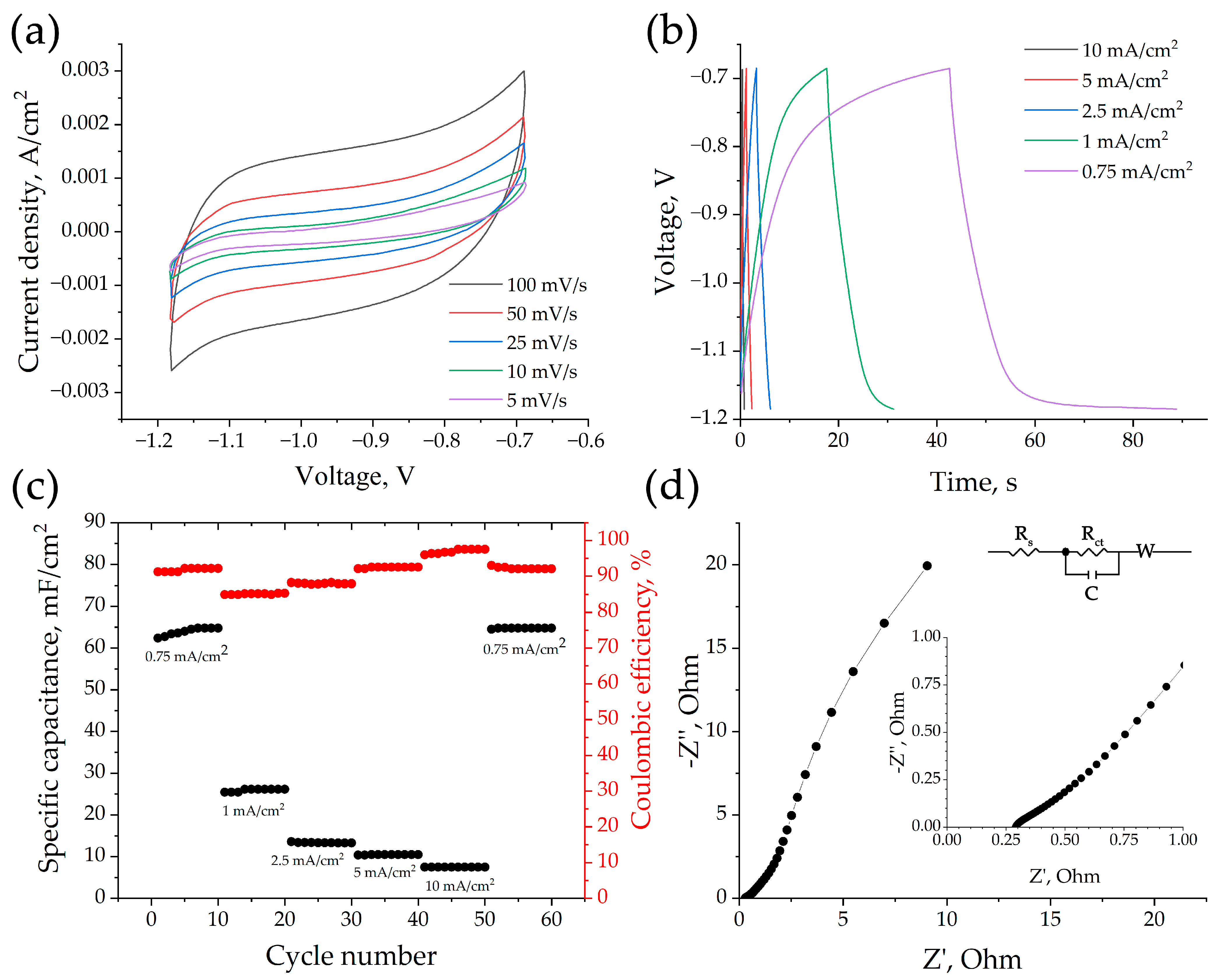
3.1. Electrochemical Properties of HfB2-HfO2-SiC-Based Sample

HfB2-HfO2-SiC. In the first stage of the study, a comprehensive electrochemical measurement of the obtained HfB2-HfO2-SiC-based ceramic sample was carried out. Cyclic voltammetry (CV) results indicate that the primary contributor to charge accumulation processes in the sample under study is the double electric layer. This is evidenced by the quasi-rectangular shape of the recorded curves (Figure 1a). It has been demonstrated that increasing the rate of potential sweep from 5 to 100 mV/s does not result in signal distortion. The curves remain symmetrical, indicating the stability and reversibility of the charge transfer processes, as well as the requisite level of kinetic characteristics.
Equation (1) was employed to quantify the specific capacitance of the working electrode, and galvanostatic charge–discharge data recorded in the same potential range as the CV curves were used.
As Figure 1b shows, decreasing the current density from 10 mA/cm2 to 0.75 mA/cm2 increases the discharge time and results in the formation of a plateau on the discharge branches, in addition to the linear section. This significantly impacts the duration of the process. As the current density increases, the specific capacitance value of the investigated electrode decreases from 64.8 to 7.5 F/cm2 (Figure 1c). This is a general characteristic of electrode materials and is caused by electrolyte ions having difficulty accessing the active centers within the material’s volume at high current densities.
The calculated values of η (Equation (2)) increase from 85 to 97.5%, which, taking into account the values of specific capacitance, allows us to consider the investigated material as a possible electrode for energy storage devices, as was previously demonstrated for ceramic samples of similar composition [8,54].
Studying the frequency dependence of electrode material impedance (Figure 1d) revealed that Nyquist diagrams in the high-frequency region lack a pronounced half-circle, potentially indicating an increased charge transfer rate [8]. The intersection of the impedance hodograph with the abscissa axis in the high-frequency range (Rs) provides information on the total resistance of the electrolyte solution and the resistance of the electrode–electrolyte interface and the electrode itself. In this case, Rs is 0.29 Ω, indicating the high conductivity of the investigated electrode material. The Rct element represents the charge transfer resistance between the Stern layer and the electrode surface [55]. As can be seen in the Figure 1 inset, the electrode material exhibits rather low Rs and Rct resistances, indicating relatively active ionic transport at the electrode/electrolyte interface. The linear component of the experimental spectrum can be described by Warburg impedance, which corresponds to the diffusion of electrolyte ions from the electrolyte’s volume to the active centers of the electrode material. Overall, the studies conducted highlight the potential application of composite ceramics based on HfB2-HfO2-SiC, obtained using 15 vol% Ti2AlC MAX-phase as a sintering component, as an anode material for energy storage devices.

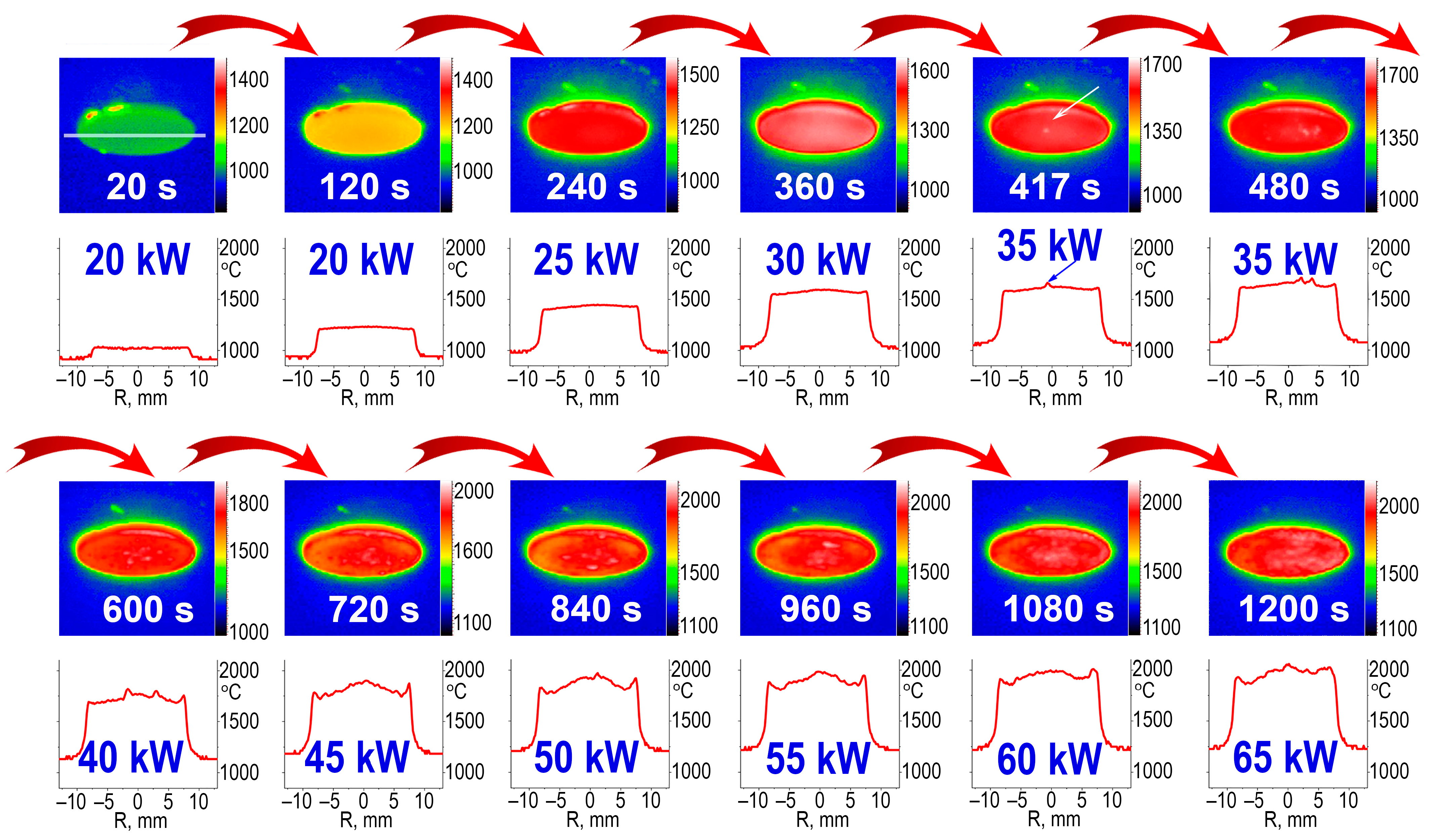
3.2. Exposure of the HfB2-HfO2-SiC-Based Sample Surface to Dissociated Airflows

When the ceramic sample was immersed in the air plasma jet at a plasmatron anode power supply of 20 kW, the average surface temperature, determined by a spectral-ratio infrared pyrometer, varied from ~1195 to 1227 °C (see Figure 2). Increasing the power to 25 kW after two minutes of exposure resulted in a stepwise increase in temperature to 1350 °C, with a subsequent tendency to increase to 1430 °C. Increasing the anode power supply to 30 kW also caused a sharp rise in the average temperature to ~1600 °C. This temperature decreased slightly to 1582 °C as the sample was held under this exposure condition. Further stepwise increases in the anode power by 5 kW every two minutes led to a less significant initial increase in temperature, followed by its constant decrease as the sample was held at temperatures slightly higher than those in the previous stage. This resulted in a gradual increase in the average surface temperature. At the same time, the increase in anode power became less and less pronounced starting from N = 50 kW. Immediately before the heating was switched off, the average surface temperature was ~2000 °C. The duration of the thermochemical effect at temperatures > 1800 °C was 10 min (after increasing N ≥ 45 kW).
Photo fixation during the heating process showed that at the beginning of the eighth minute at N = 35 kW, distinct bright spots with a diameter of 0.2–0.3 mm formed on the sample surface.
This phenomenon was concomitant with the formation of bulges (as a consequence of the formation of melt bubbles) and the attendant temperature increase. As the exposure level increased, the number of these superheated areas increased as well. By the end of the 12th minute, these areas had merged into a single relief layer of silicate melt on the surface.
Studying changes in the temperature distribution on the surface of ceramics during exposure to high-temperature air plasma using the thermal imager enables the detection of local superheated regions (ΔT~40°) somewhat earlier, at 417 s (Figure 3, indicated by an arrow). Up to this point, it is evident that the temperature distribution over the surface was uniform. It has been demonstrated that increasing the anode power of the plasmatron results in an increase in the average surface temperature, as well as an increase in the number of individual superheated areas. Upon reaching N = 45 kW, these individual superheated areas coalesce into large superheated areas in the center of the sample. Concurrently, the overheating of the sample edges, a phenomenon characteristic of the heating of ultrahigh-temperature ceramics with subsonic airflow, is also observed [56,57,58]. In earlier studies, it was demonstrated that the presence of overheated regions resulted in the intensification of evaporation from the surface of the protective layer of borosilicate melt. This, in turn, led to a phenomenon referred to as a “temperature jump” [59], which caused the temperature to span approximately 2400–2700 °C across the entire surface of the sample. However, this effect was not observed in the present study, even when the temperature was elevated to 1800–1850 °C.
After a 1200 s exposure to a subsonic jet of dissociated air, the heating process was terminated. It was determined that the average surface temperature decreased by approximately 1000 °C in 10 s during the cooling process. However, no destruction of the sample or delamination of the oxidized surface area was observed.
The total mass gain of the ceramic sample was 0.39% (corresponding to a relative mass gain rate of ~+1.0·10−2 g·cm−2·min−1). An increase in sample thickness was observed, which can be explained by swelling of the oxidized surface. The approximate increase in thickness was ~0.45 mm (+12%).

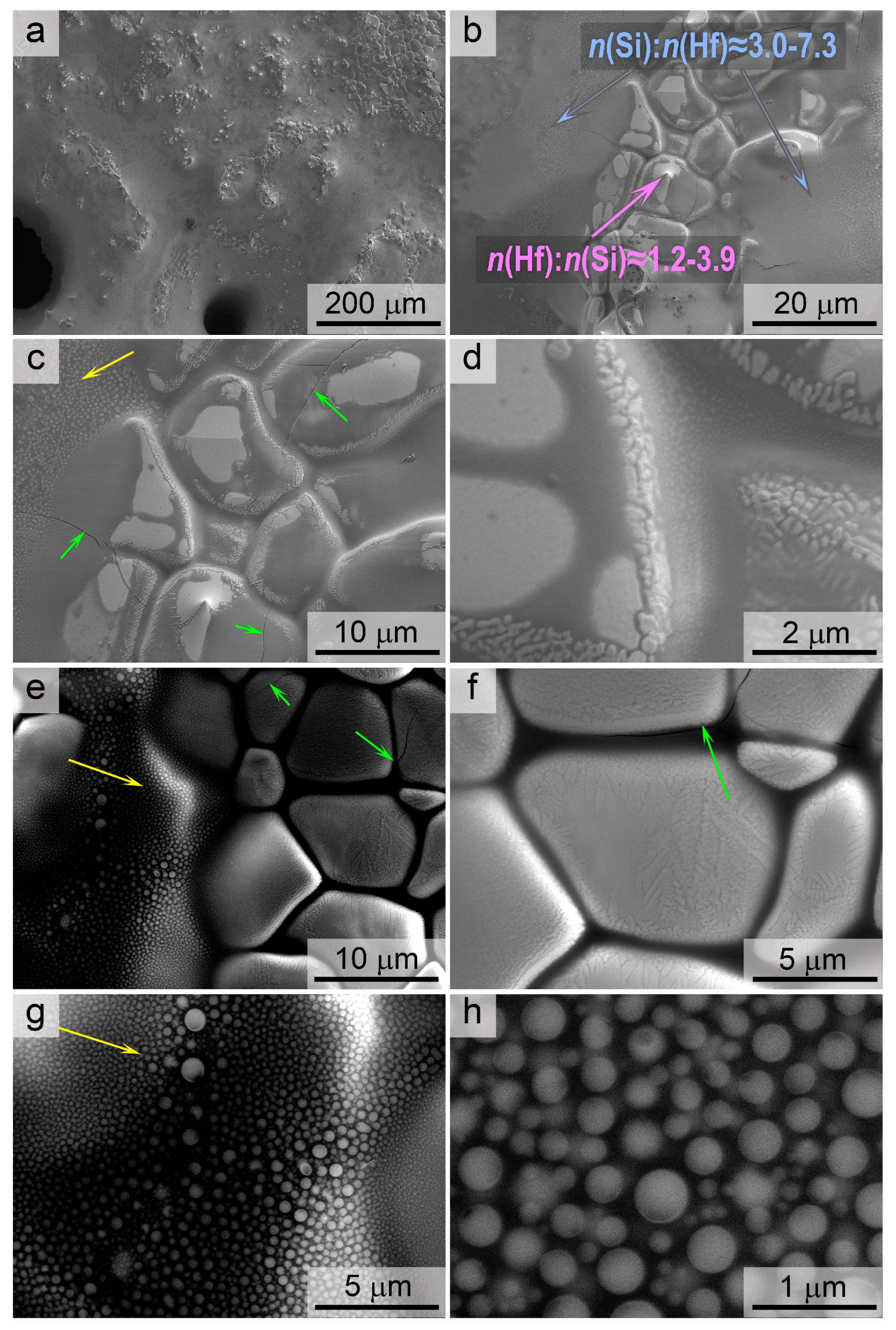
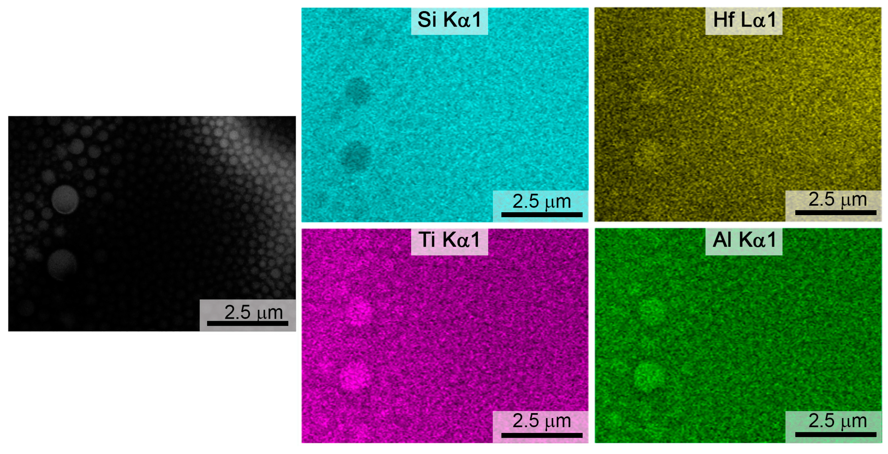
3.3. Investigation of Surface Degradation of HfB2-HfO2-SiC-Based Material After Exposure to Subsonic Flow of Dissociated Air

XRD of the oxidized surface (Figure 4) revealed that the predominant crystalline phase among the oxidation products is monoclinic HfO2 [60] (ICDD 00-034-0104) with a minor admixture of its cubic modification [61]. The following phases were identified on the surface of the sample during the present study: silicon carbide, HfB2 [62] (ICDD 00-038-1398), a solid solution of HfB2-TiB2, and a cubic solid solution of the (Hf,Ti)(C,B) system. These phases are typical of initial ceramics. However, the presence of silicon carbide, HfB [63] (ICDD 00-030-0612), and hafnium monocarbide (HfC) [64] (ICDD 00-039-1491) was not observed. This may indicate a sufficiently deep oxidation of the material and the formation of a thick layer of oxides on the surface.
Furthermore, analysis of the surface IR reflectance spectrum reveals the absence of a band characteristic of SiC, with a maximum at ~800 cm−1 [65,66,67,68] (Figure 5, spectrum 1). However, the spectrum displays Si-O-Si reflectance bands with a maximum at 1100 cm−1 and a shoulder at 1235 cm−1, in addition to a significantly less intense Si-O-Ti band with a maximum at 935 cm−1 [69,70].
Figure 5 shows the Raman spectra of the initial sample (1), the near-surface region of the chip, and the surface of the sample after exposure to a subsonic air plasma flow. As can be seen, the original sample (1) exhibits characteristic silicon carbide modes—ωSi1Si4 at 264, 772, 795, 950, and 976 cm−1 [71]—and weak peaks of the monoclinic HfO2 phases—ωH1H12 at 151, 246, 276, 336, 383, 401, 500, 524, 554, 585, 645, and 676 cm−1 [72]—as well as anatase TiO2—ωT at ~139 cm−1 (Eg) [73]. The anatase phase was not detected by XRD (see Figure 4), probably due to its low content. It may have formed as a result of the interaction between Ti2AlC and HfO2 during the consolidation of the original ceramic sample. Spectra recorded in the near-surface region of the chip (2) and on the surface (3) differ significantly from those of the undegraded HfB2-HfO2-SiC-based ceramic. In particular, the spectra lack silicon carbide bands and all TiO2 and HfO2 peaks become intense and pronounced. The surface also shows a low-intensity peak at ~298 cm−1, which correlates well with the most intense mode of the aluminum titanate phase, Al2TiO5 [74], which may have crystallized from the silicate melt during cooling of the sample.
Study of the microstructure of the sample surface after exposure to an air plasma flow using the SEM method (Figure 6) showed that it is completely covered by a vitreous layer through which clusters of large particles (up to 10 µm) can be seen. EDX analysis of an area measuring 130 × 180 µm revealed that the overall surface ratio of n(Si):n(Hf) is ~2–2.5. However, in areas with large particles, the hafnium content is higher: n(Hf):n(Si) is 1.2–3.9. The silicon content is extremely high in the troughs between these areas (n(Si):n(Hf) = 3.0–7.3). At the same time, the vitreous phase is enriched in aluminum compared to the HfO2-based solid phase. Using a higher accelerating voltage (20 kV) revealed (Figure 6e–h) that liquation, the formation of 100–450 nm diameter drops of a second vitreous phase that does not mix with the basic silicate melt, occurs within the volume of the formed vitreous phase. Mapping the distribution of the elements Si, Hf, Ti, and Al in the area of melt localization on the surface (Figure 7) indicates that spherical liquation heterogeneities are enriched in titanium and aluminum oxides and, to a lesser extent, hafnium oxide, while silicon oxide prevails in the composition of the main melt phase.
Exposure has significantly altered the microstructure of the chipped sample (Figure 8), with the thickness of the degradation layer varying from 550 to 850 μm. This is probably due to the formation and rupture of gas bubbles containing oxidation products from the HfB2-HfO2-SiC ceramic system. Most of the pores resulting from these gas bubbles are elongated from the volume to the surface. However, in the lower part of the oxidized layer, directly adjacent to the unoxidized ceramic volume, the pores are much smaller and extend across the surface. The upper, most-porous and -molten part of the degradation region, at the experimental temperature, is a mixture of a vitreous phase containing hafnium oxide particles. Applying a higher accelerating voltage (20 kV; Figure 9) confirms this, revealing more absorbing HfO2 particles of arbitrary shape and measuring ~2–20 µm in size, as well as spherical particles of the second melt phase with a diameter of 150–600 nm, distributed within the silicate melt volume. This corresponds to the sizes of liquation inhomogeneities recorded on the surface (Figure 6).
Mapping the distribution of the Hf, Si, O, Ti, and Al elements by chipping in the region immediately adjacent to the bulk of the ceramic (see Figure 10) shows that the layer of relatively small horizontal pores in the oxidized near-surface region is ~60–100 µm thick. In the degradation region, hafnium oxide forms weakly bound particle aggregates, and the silicon, titanium, and aluminum contents decrease relative to those in the bulk of the sample, probably due to foaming of the oxidation products.

4. Conclusions

Analysis of the obtained experimental data allows us to conclude that modifying the composition of ultrahigh-temperature ceramics with the Ti2AlC carbide phase during fabrication increases the viscosity of the silicate melt protective layer through the observed liquation phenomenon. Consequently, even at temperatures as high as 1900–2000 °C on the surface, there is no significant entrainment of the upper liquid melt layer in the form of droplets. Additionally, modifying the silicate melt composition with refractory oxides (TiO2, Al2O3) probably reduces the intensity with which its components vaporize at temperatures of ~1750–1850 °C. This prevents the sharp increase in surface temperature often observed up to values of >2400–2500 °C (the “temperature jump” effect [56,57,58,59]).
This allows us to draw the preliminary conclusion that modifying ultrahigh-temperature ceramics simultaneously with titanium and aluminum refractory compounds can improve the material’s overall oxidation resistance. However, this issue requires more detailed, systematic studies to determine the optimal ratio of UHTC components. In particular, it would be useful to conduct experiments to determine the effect of the oxidation behavior of the material on the content of the introduced sintering additive Ti2AlC, as this would also improve the ceramic densification process.
In general, the studies in this work have demonstrated the potential of using MAX-phases as sintering additives for ultrahigh-temperature ceramics based on hafnium and zirconium diborides. This improves the densification process without compromising the oxidation resistance of the material, not only within the temperature range of 20–1200 °C, as demonstrated in previous studies [48], but also when exposed to subsonic flows of dissociated air at temperatures up to 2000 °C. Furthermore, electrochemical measurements in a liquid electrolyte medium based on potassium hydroxide revealed that the investigated material demonstrates competitive values of specific capacitance (64.8 mF/cm2 at current density of 0.75 mA/cm2) and coulombic efficiency (up to 97.5% at 10 mA/cm2), which allows us to consider it a promising electrode material for supercapacitors.

Author Contributions

Conceptualization, E.P.S. and A.V.C.; methodology, A.F.K. and N.T.K.; investigation, A.V.C., E.P.S., N.P.S., I.V.L., S.S.G., A.S.L., I.A.N., A.S.M. and T.L.S.; writing—original draft preparation, E.P.S. and A.V.C.; writing—review and editing, N.P.S., I.V.L., S.S.G., A.S.L., I.A.N., A.S.M., T.L.S. and A.F.K.; visualization, E.P.S., N.P.S., S.S.G. and A.V.C.; supervision, A.F.K. and N.T.K.; project administration, A.V.C. and E.P.S.; funding acquisition, E.P.S. All authors have read and agreed to the published version of the manuscript.

Funding

This research was supported by the Russian Science Foundation (project No. 24-23-00561, https://rscf.ru/en/project/24-23-00561/, accessed on 25 November 2024).

Institutional Review Board Statement

Not applicable.

Informed Consent Statement

Not applicable.

Data Availability Statement

Data are contained within the article.

Conflicts of Interest

The authors declare no conflicts of interest.

References

  1. Simonenko, E.P.; Sevast’yanov, D.V.; Simonenko, N.P.; Sevast’yanov, V.G.; Kuznetsov, N.T. Promising Ultra-High-Temperature Ceramic Materials for Aerospace Applications. Russ. J. Inorg. Chem. 2013, 58, 1669–1693. [Google Scholar] [CrossRef]
  2. Silvestroni, L.; Savino, R.; Cecere, A.; Mungiguerra, S. Failure Tolerant Functionally Graded Fiber-Reinforced UHTCs Exposed to Hypersonic Flows. Compos. Part A Appl. Sci. Manuf. 2024, 185, 108293. [Google Scholar] [CrossRef]
  3. Cecere, A.; Savino, R.; Allouis, C.; Monteverde, F. Heat Transfer in Ultra-High Temperature Advanced Ceramics under High Enthalpy Arc-Jet Conditions. Int. J. Heat Mass Transf. 2015, 91, 747–755. [Google Scholar] [CrossRef]
  4. Parthasarathy, T.A.; Petry, M.D.; Cinibulk, M.K.; Mathur, T.; Gruber, M.R. Thermal and Oxidation Response of UHTC Leading Edge Samples Exposed to Simulated Hypersonic Flight Conditions. J. Am. Ceram. Soc. 2013, 96, 907–915. [Google Scholar] [CrossRef]
  5. Squire, T.H.; Marschall, J. Material Property Requirements for Analysis and Design of UHTC Components in Hypersonic Applications. J. Eur. Ceram. Soc. 2010, 30, 2239–2251. [Google Scholar] [CrossRef]
  6. Gupta, K.; Murtaza, Q.; Yuvraj, N. Development of ZrB2-SiC Plasma-Sprayed Ceramic Coating for Thermo-Chemical Protection in Hypersonic Vehicles. J. Mater. Eng. Perform. 2024, 33, 1401–1410. [Google Scholar] [CrossRef]
  7. Li, P.; Ge, Y.; Jin, X.; Lu, P.; Hou, C.; Wang, H.; Fan, X. Cyclic Thermal Shock Behaviors of ZrB2-SiC Laminated Ceramics Sintered with Different-Sized Particles for Each Sublayer. J. Aust. Ceram. Soc. 2023, 59, 645–655. [Google Scholar] [CrossRef]
  8. Paksoy, A.; Yıldırım, İ.D.; Arabi, S.; Güngör, A.; Erdem, E.; Balcı-Çağıran, Ö. Enhanced Performance and Cycling Behavior in Symmetric Supercapacitors Developed by Pure HfB2 and HfB2-SiC Composites. J. Alloys Compd. 2024, 983, 173749. [Google Scholar] [CrossRef]
  9. Li, Y.; Zhao, S.; Wu, Z. Uncovering the Effects of Chemical Disorder on the Irradiation Resistance of High-Entropy Carbide Ceramics. Acta Mater. 2024, 277, 120187. [Google Scholar] [CrossRef]
  10. Barbarossa, S.; Orrù, R.; Cao, G.; Balbo, A.; Zanotto, F.; Sani, E. Optical Properties of Bulk High-Entropy Diborides for Solar Energy Applications. J. Alloys Compd. 2023, 935, 167965. [Google Scholar] [CrossRef]
  11. Chen, Y. Ultra-High-Temperature Ceramic Materials Modified By Graphene: An Overview. Ceram. Silik. 2023, 67, 260–296. [Google Scholar] [CrossRef]
  12. Kim, S.Y.; Sesso, M.L.; Franks, G.V. Effect of Internal Lattice Structure on the Flexural Strength of 3D Printed Hierarchical Porous Ultra-High Temperature Ceramic (ZrB2). J. Eur. Ceram. Soc. 2023, 43, 1762–1776. [Google Scholar] [CrossRef]
  13. Zhang, Z.; Fang, W.; Zhang, M.; Zeng, C.; Huang, Q. Enhanced Mechanical and Ablation Properties of Lamellar Porous ZrB2-SiC Ceramics by Highly Textured Pyrolytic Carbon. Corros. Sci. 2025, 250, 112882. [Google Scholar] [CrossRef]
  14. Zhao, K.; Ye, F.; Cheng, L.; Yang, J.; Chen, X. An Overview of Ultra-High Temperature Ceramic for Thermal Insulation: Structure and Composition Design with Thermal Conductivity Regulation. J. Eur. Ceram. Soc. 2023, 43, 7241–7262. [Google Scholar] [CrossRef]
  15. Simonenko, E.P.; Kolesnikov, A.F.; Chaplygin, A.V.; Kotov, M.A.; Yakimov, M.Y.; Lukomskii, I.V.; Galkin, S.S.; Shemyakin, A.N.; Solovyov, N.G.; Lysenkov, A.S.; et al. Oxidation of Ceramic Materials Based on HfB2-SiC under the Influence of Supersonic CO2 Jets and Additional Laser Heating. Int. J. Mol. Sci. 2023, 24, 13634. [Google Scholar] [CrossRef]
  16. Jin, H.; Meng, S.; Zhang, X.; Zeng, Q.; Niu, J. Effects of Oxidation Temperature, Time, and Ambient Pressure on the Oxidation of ZrB2–SiC–graphite Composites in Atomic Oxygen. J. Eur. Ceram. Soc. 2016, 36, 1855–1861. [Google Scholar] [CrossRef]
  17. Sciti, D.; Vinci, A.; Zoli, L.; Galizia, P.; Mor, M.; Fahrenholtz, W.; Mungiguerra, S.; Savino, R.; Caporale, A.M.; Airoldi, A. Elevated Temperature Performance: Arc-Jet Testing of Carbon Fiber Reinforced ZrB2 Bars up to 2200 °C for Strength Retention Assessment. J. Adv. Ceram. 2025, 14, 9221022. [Google Scholar] [CrossRef]
  18. Nisar, A.; Zhang, C.; Boesl, B.; Agarwal, A. Synthesis of Hf6Ta2O17 Superstructure via Spark Plasma Sintering for Improved Oxidation Resistance of Multi-Component Ultra-High Temperature Ceramics. Ceram. Int. 2023, 49, 783–791. [Google Scholar] [CrossRef]
  19. Meng, S.; Zeng, Q.; Jin, H.; Wang, L.; Xu, C. Evaluation of Atomic Oxygen Catalytic Coefficient of ZrB2–SiC by Laser-Induced Fluorescence up to 1473 K. Meas. Sci. Technol. 2018, 29, 075207. [Google Scholar] [CrossRef]
  20. Paksoy, A.; Buldu-Akturk, M.; Arabi, S.; Erdem, E.; Balcı-Çağıran, Ö. Synthesis and Capacitive Performance of ZrB2 and Its Composites as Supercapacitor Electrodes. Solid State Sci. 2023, 142, 107256. [Google Scholar] [CrossRef]
  21. Rezaie, A.; Fahrenholtz, W.G.; Hilmas, G.E. Effect of Hot Pressing Time and Temperature on the Microstructure and Mechanical Properties of ZrB2–SiC. J. Mater. Sci. 2007, 42, 2735–2744. [Google Scholar] [CrossRef]
  22. Zhu, S.; Fahrenholtz, W.G.; Hilmas, G.E. Influence of Silicon Carbide Particle Size on the Microstructure and Mechanical Properties of Zirconium Diboride–silicon Carbide Ceramics. J. Eur. Ceram. Soc. 2007, 27, 2077–2083. [Google Scholar] [CrossRef]
  23. Guo, S.-Q. Densification of ZrB2-Based Composites and Their Mechanical and Physical Properties: A Review. J. Eur. Ceram. Soc. 2009, 29, 995–1011. [Google Scholar] [CrossRef]
  24. Zhao, B.; Jiang, Y.; Yang, B.; Wang, T.; Hu, Y.; Sun, D.; Li, R.; Yin, S.; Li, J.; Feng, Z.; et al. Reactive Sintering of Tungsten-Doped High Strength ZrB2–SiC Porous Ceramics Using Metastable Precursors. Mater. Res. Bull. 2014, 51, 19–23. [Google Scholar] [CrossRef]
  25. Simonenko, E.P.; Papynov, E.K.; Shichalin, O.O.; Belov, A.A.; Nagornov, I.A.; Simonenko, T.L.; Gorobtsov, P.Y.; Teplonogova, M.A.; Mokrushin, A.S.; Simonenko, N.P.; et al. Reactive Spark Plasma Sintering and Oxidation of ZrB2-SiC and ZrB2-HfB2-SiC Ceramic Materials. Ceramics 2024, 7, 1566–1583. [Google Scholar] [CrossRef]
  26. Nguyen, V.-Q.; Kim, J.-S.; Seo, H.; Lee, S.-H. Effects of High-Energy Ball Milling and Reactive Spark Plasma Sintering on the Densification, Microstructure, and Mechanical Properties of Ultra-Fine and X-Ray Pure ZrB2-SiC Composites. J. Eur. Ceram. Soc. 2024, 44, 116714. [Google Scholar] [CrossRef]
  27. Fazili, A.; Irankhah, R.; Shirani, M.; Nikzad, L.; Razavi, M.; Asadian, K. Comparison of ZrB2-SiC Composites Fabricated Through Reactive and Non-Reactive Methods. J. Mater. Eng. Perform. 2023, 32, 10728–10739. [Google Scholar] [CrossRef]
  28. Simonenko, E.P.; Simonenko, N.P.; Lysenkov, A.S.; Sevastyanov, V.G.; Kuznetsov, N.T. Reactive Hot Pressing of HfB2–SiC–Ta4HfC5 Ultra-High Temperature Ceramics. Russ. J. Inorg. Chem. 2020, 65, 446–457. [Google Scholar] [CrossRef]
  29. Shahedi Asl, M.; Nayebi, B.; Shokouhimehr, M. TEM Characterization of Spark Plasma Sintered ZrB2–SiC–graphene Nanocomposite. Ceram. Int. 2018, 44, 15269–15273. [Google Scholar] [CrossRef]
  30. Wang, H.; Lee, S.-H.; Feng, L. HfB2–SiC Composite Prepared by Reactive Spark Plasma Sintering. Ceram. Int. 2014, 40, 11009–11013. [Google Scholar] [CrossRef]
  31. Simonenko, E.P.; Simonenko, N.P.; Chaplygin, A.V.; Lukomskii, I.V.; Galkin, S.S.; Lysenkov, A.S.; Nagornov, I.A.; Mokrushin, A.S.; Kolesnikov, A.F.; Kuznetsov, N.T. Surface Degradation of Ultrahigh-Temperature Ceramics Based on HfB2–30vol%SiC in Subsonic Nitrogen Plasma Flow. Int. J. Refract. Met. Hard Mater. 2025, 130, 107139. [Google Scholar] [CrossRef]
  32. Mehdipour, M.; Balak, Z.; Azizieh, M.; Shahedi Asl, M. Optimization of SPS Parameters and Graphene Content with the Aim of Improving Densification and Flexural Strength of ZrB2-SiC Composites. JOM 2025, 77, 2001–2012. [Google Scholar] [CrossRef]
  33. Zoli, L.; Servadei, F.; Failla, S.; Mor, M.; Vinci, A.; Galizia, P.; Sciti, D. ZrB2–SiC Ceramics Toughened with Oriented Paper-Derived Graphite for a Sustainable Approach. J. Adv. Ceram. 2024, 13, 207–219. [Google Scholar] [CrossRef]
  34. Tripathi, S.; Bhadauria, A.; Tiwari, A.; Tiwari, A.K. Effect of Carbonaceous Reinforcements on Mechanical Properties of ZrB2-SiC Composites via Nanoindentation Study. Diam. Relat. Mater. 2023, 140, 110537. [Google Scholar] [CrossRef]
  35. Cheng, Y.; Liu, Y.; An, Y.; Hu, N. High Thermal-Conductivity RGO/ZrB2-SiC Ceramics Consolidated from ZrB2-SiC Particles Decorated GO Hybrid Foam with Enhanced Thermal Shock Resistance. J. Eur. Ceram. Soc. 2020, 40, 2760–2767. [Google Scholar] [CrossRef]
  36. He, L.; Wu, J.; Meng, Q.; Sun, Y.; Pan, J.; Tian, Y.; Wu, F. Study on Low Content Short Carbon Fibers to Enhance Mechanical Properties of ZrB2-SiC Composites with Improved Damage Tolerance. Mater. Today Commun. 2025, 42, 111391. [Google Scholar] [CrossRef]
  37. Gardini, D.; Backman, L.; Kaczmarek, P.; Capiani, C.; Sangiorgi, A.; Melandri, C.; Silvestroni, L. Viable Route to the Manufacture of Short Carbon Fiber-Rich UHTC Complex Shapes with Enhanced Toughness. Compos. Part B Eng. 2024, 277, 111373. [Google Scholar] [CrossRef]
  38. Murthy, S.S.N.; Patel, M.; Panigrahi, B.B. Processing of Continuous Carbon Fibre Reinforced ZrB2-SiC Composite Through In-Situ Matrix Development. Trans. Indian Inst. Met. 2024, 77, 2461–2469. [Google Scholar] [CrossRef]
  39. Gupta, N.; Mukhopadhyay, A.; Pavani, K.; Basu, B. Spark Plasma Sintering of Novel ZrB2–SiC–TiSi2 Composites with Better Mechanical Properties. Mater. Sci. Eng. A 2012, 534, 111–118. [Google Scholar] [CrossRef]
  40. Ahmadi, Z.; Shahedi Asl, M.; Zakeri, M.; Farvizi, M. On the Reactive Spark Plasma Sinterability of ZrB2–SiC–TiN Composite. J. Alloys Compd. 2022, 909, 164611. [Google Scholar] [CrossRef]
  41. Xia, C.; Delbari, S.A.; Ahmadi, Z.; Shahedi Asl, M.; Ghassemi Kakroudi, M.; Van Le, Q.; Sabahi Namini, A.; Mohammadi, M.; Shokouhimehr, M. Electron Microscopy Study of ZrB2–SiC–AlN Composites: Hot-Pressing vs. Pressureless Sintering. Ceram. Int. 2020, 46, 29334–29338. [Google Scholar] [CrossRef]
  42. Nasiri, Z.; Mashhadi, M. Microstructure and Mechanical Behavior of Ternary Phase ZrB2-SiC-AlN Nanocomposite. Int. J. Refract. Met. Hard Mater. 2019, 78, 186–192. [Google Scholar] [CrossRef]
  43. Sengupta, P.; Manna, I. Role of TiC and WC Addition on the Mechanism and Kinetics of Isothermal Oxidation and High-Temperature Stability of ZrB2–SiC Composites. High Temp. Corros. Mater. 2024, 101, 57–83. [Google Scholar] [CrossRef]
  44. Duan, X.; Wei, C.; Geng, X.; Meng, F.; Zhou, L.; Wang, P.; Dong, Z.; Dong, S. Effects of Adding Si3N4 Whiskers to ZrB2–SiC Ceramics on Microstructure, Mechanical Properties and Oxidation Resistance. Ceram. Int. 2024, 50, 43153–43164. [Google Scholar] [CrossRef]
  45. Sarhangian, M.; Mashhadi, M. The Impact of Si3N4 Incorporation on the Mechanical Characteristics of ZrB2–SiC Nanocomposite Sintered via Pressureless Method. Heliyon 2024, 10, e33269. [Google Scholar] [CrossRef]
  46. Wei, C.; Liu, L.; Sun, M.; Wang, P.; Meng, F.; Chen, D.; Han, Q.; Yu, Z. Ablation Performance and Mechanism of Fibrous Monolithic ZrB2-SiC Ceramics Prepared by Wet-Spinning Co-Extrusion Method under Plasma Flame. Ceram. Int. 2024, 50, 11548–11556. [Google Scholar] [CrossRef]
  47. Zhang, M.; Hu, D.; Fu, Q. Ablation Resistant Behavior of Silicide Modified HfB2-SiC Coating on Graphite by Spark Plasma Sintering: Role of MeSi2 Addition. J. Eur. Ceram. Soc. 2024, 44, 6286–6297. [Google Scholar] [CrossRef]
  48. Simonenko, E.P.; Nagornov, I.A.; Lysenkov, A.S.; Papynov, E.K.; Shichalin, O.O.; Belov, A.A.; Kolodeznikov, E.S.; Mokrushin, A.S.; Simonenko, N.P.; Kuznetsov, N.T. Effect of Ti2AlC on Sintering of Ultrahigh-Temperature Ceramics Based on HfB2–HfO2–SiC System. Russ. J. Inorg. Chem. 2024, 69, 2151–2163. [Google Scholar] [CrossRef]
  49. Simonenko, E.P.; Nagornov, I.A.; Mokrushin, A.S.; Sapronova, V.M.; Gorobtsov, P.Y.; Simonenko, N.P.; Kuznetsov, N.T. Synthesis of Ti2AlC in KBr Melt: Effect of Temperature and Component Ratio. Russ. J. Inorg. Chem. 2024, 69, 1744–1753. [Google Scholar] [CrossRef]
  50. Simonenko, E.P.; Nagornov, I.A.; Mokrushin, A.S.; Kashevsky, S.V.; Gorban, Y.M.; Simonenko, T.L.; Simonenko, N.P.; Kuznetsov, N.T. Low Temperature Chemoresistive Oxygen Sensors Based on Titanium-Containing Ti2CTx and Ti3C2Tx MXenes. Materials 2023, 16, 4506. [Google Scholar] [CrossRef]
  51. Chaplygin, A.V.; Vasil’evskii, S.A.; Galkin, S.S.; Kolesnikov, A.F. Thermal State of Uncooled Quartz Discharge Channel of Powerful High-Frequency Induction Plasmatron. Phys. Kinet. Gas Dyn. 2022, 23, 38–56. [Google Scholar] [CrossRef]
  52. Gordeev, A. Overview of Characteristics and Experiments in IPM Plasmatrons. VKI RTO AVT/VKI Spec. Course Meas. Tech. High Enthalpy Plasma Flows1999, RTO EN-8, Belgium. Available online: https://apps.dtic.mil/sti/citations/ADP010736 (accessed on 1 June 2025).
  53. ASTM E457-08(2015); Standard Test Method for Measuring Heat-Transfer Rate Using a Thermal Capacitance. ASTM International: West Conshohocken, PA, USA. Available online: http://www.astm.org (accessed on 1 June 2025).
  54. Li, X.; Wei, Z.; Zu, Y.; Chen, G.; Fu, X.; Zhou, W. Phase Composition and Electrochemical Properties of (Hf0.2Zr0.2Ta0.2Mo0.2Ti0.2)B2 High-Entropy Ceramics. J. Ceram. 2023, 44, 688–694. [Google Scholar] [CrossRef]
  55. Khayyam Nekouei, R.S.; Mofarah, S.; Maroufi, S.; Tudela, I.; Sahajwalla, V. Determination of the Optimum Potential Window for Super- and Pseudocapacitance Electrodes via in-Depth Electrochemical Impedance Spectroscopy Analysis. J. Energy Storage 2022, 56, 106137. [Google Scholar] [CrossRef]
  56. Simonenko, E.P.; Simonenko, N.P.; Gordeev, A.N.; Kolesnikov, A.F.; Lysenkov, A.S.; Nagornov, I.A.; Sevastyanov, V.G.; Kuznetsov, N.T. The Effects of Subsonic and Supersonic Dissociated Air Flow on the Surface of Ultra-High-Temperature HfB2-30 Vol% SiC Ceramics Obtained Using the Sol-Gel Method. J. Eur. Ceram. Soc. 2020, 40, 1093–1102. [Google Scholar] [CrossRef]
  57. Simonenko, E.P.; Simonenko, N.P.; Gordeev, A.N.; Kolesnikov, A.F.; Sevastyanov, V.G.; Kuznetsov, N.T. Impact of a Subsonic Dissociated Air Flow on the Surface of HfB2–30 Vol% SiC UHTC Produced by the Sol–Gel Method. Russ. J. Inorg. Chem. 2018, 63, 1345–1355. [Google Scholar] [CrossRef]
  58. Sevastyanov, V.G.; Simonenko, E.P.; Gordeev, A.N.; Simonenko, N.P.; Kolesnikov, A.F.; Papynov, E.K.; Shichalin, O.O.; Avramenko, V.A.; Kuznetsov, N.T. HfB2-SiC (10–20 Vol%) Ceramic Materials: Manufacture and Behavior under Long-Term Exposure to Dissociated Air Streams. Russ. J. Inorg. Chem. 2014, 59, 1361–1382. [Google Scholar] [CrossRef]
  59. Marschall, J.; Pejakovic, D.; Fahrenholtz, W.G.; Hilmas, G.E.; Panerai, F.; Chazot, O. Temperature Jump Phenomenon during Plasmatron Testing of ZrB2-SiC Ultrahigh-Temperature Ceramics. J. Thermophys. Heat Transf. 2012, 26, 559–572. [Google Scholar] [CrossRef]
  60. Ruh, R.; Corfield, P.W.R. Crystal Structure of Monoclinic Hafnia and Comparison with Monoclinic Zirconia. J. Am. Ceram. Soc. 1970, 53, 126–129. [Google Scholar] [CrossRef]
  61. Wyckoff, R.W.G. Fluorite Structure. In Crystal Structures, 2nd ed.; Interscience Publishers: New York, NY, USA, 1963; pp. 239–444. [Google Scholar]
  62. Holleck, H. Legierungsverhalten von HfB2 Mit Uran- Und Übergangsmetalldiboriden. J. Nucl. Mater. 1967, 21, 14–20. [Google Scholar] [CrossRef]
  63. Shulishova, O.I.; Shcherbak, I.A. Superconductivity of the Borides of Transition and Rare-Earth Metals. Inorg. Mater. 1967, 3, 1304–1306. [Google Scholar]
  64. Aigner, K.; Lengauer, W.; Rafaja, D.; Ettmayer, P. Lattice Parameters and Thermal Expansion of Ti(CxN1−x), Zr(CxN1−x), Hf(CxN1−x) and TiN1−x from 298 to 1473 K as Investigated by High-Temperature X-Ray Diffraction. J. Alloys Compd. 1994, 215, 121–126. [Google Scholar] [CrossRef]
  65. Declémy, A.; Oliviero, E.; Beaufort, M.F.; Barbot, J.F.; David, M.L.; Blanchard, C.; Tessier, Y.; Ntsoenzok, E. An IR-Reflectivity and X-Ray Diffraction Study of High Energy He-Ion Implantation-Induced Damage in 4H–SiC. Nucl. Instruments Methods Phys. Res. Sect. B Beam Interact. Mater. Atoms 2002, 186, 318–323. [Google Scholar] [CrossRef]
  66. Yoshida, S.; Hijikata, Y.; Yaguchi, H. Nondestructive and Contactless Characterization Method for Spatial Mapping of the Thickness and Electrical Properties in Homo-Epitaxially Grown SiC Epilayers Using Infrared Reflectance Spectroscopy. In Physics and Technology of Silicon Carbide Devices; InTech: Daejeon, Korea, 2012. [Google Scholar]
  67. Hofmeister, A.M.; Pitman, K.M.; Goncharov, A.F.; Speck, A.K. Optical Constamts of Silicon Carbide for Astrophysical Applications. II. Extending Optical Functions from Infrared to Ultraviolet Using Single-Crystal Absorptionspectra. Astrophys. J. 2009, 696, 1502–1516. [Google Scholar] [CrossRef]
  68. Pavlikov, A.V.; Latukhina, N.V.; Chepurnov, V.I.; Timoshenko, V.Y. Structural and Optical Properties of Silicon-Carbide Nanowires Produced by the High-Temperature Carbonization of Silicon Nanostructures. Semiconductors 2017, 51, 402–406. [Google Scholar] [CrossRef]
  69. Shcherbakov, I.P.; Narykova, M.V.; Chmel, A.E. Evolution of Structural Defects of SiO2/TiO2 Glasses with a Change in TiO2 Concentration from Zero to Phase Separation. Phys. Solid State 2023, 65, 588. [Google Scholar] [CrossRef]
  70. Kim, H.J.; Roh, D.K.; Chang, J.H.; Kim, D.-S. SiO2 Coated Platy TiO2 Designed for Noble UV/IR-Shielding Materials. Ceram. Int. 2019, 45, 16880–16885. [Google Scholar] [CrossRef]
  71. Bechelany, M.; Brioude, A.; Cornu, D.; Ferro, G.; Miele, P. A Raman Spectroscopy Study of Individual SiC Nanowires. Adv. Funct. Mater. 2007, 17, 939–943. [Google Scholar] [CrossRef]
  72. Quintard, P.E.; Barbéris, P.; Mirgorodsky, A.P.; Merle-Méjean, T. Comparative Lattice-Dynamical Study of the Raman Spectra of Monoclinic and Tetragonal Phases of Zirconia and Hafnia. J. Am. Ceram. Soc. 2002, 85, 1745–1749. [Google Scholar] [CrossRef]
  73. Frank, O.; Zukalova, M.; Laskova, B.; Kürti, J.; Koltai, J.; Kavan, L. Raman Spectra of Titanium Dioxide (Anatase, Rutile) with Identified Oxygen Isotopes (16, 17, 18). Phys. Chem. Chem. Phys. 2012, 14, 14567. [Google Scholar] [CrossRef]
  74. Öhman, S.; Qiu, R.; Edvinsson, T.; Bäcke, O.; Törndahl, T.; Boman, M. Selective Kinetic Growth and Role of Local Coordination in Forming Al2TiO5 Based Coatings at Lower Temperatures. Mater. Adv. 2021, 2, 5737–5751. [Google Scholar] [CrossRef]
Figure 1. Cyclic voltammetry curves (a), galvanostatic charge–discharge curves (b), variation in specific capacitance and coulombic efficiency values during working cycles (c), and Nyquist diagram and proposed equivalent circuit for the investigated ceramic sample (d).
Cmd 06 00035 g001
Figure 2. The variation in the average surface temperature (T, °C, red curve) of the sample is demonstrated as a function of the duration of exposure (t, s), anode power (N, kW, green curve), and pressure in the plasmatron chamber (P, kPa, blue curve). The inset illustrates the appearance of the sample fixed in the water-cooled holder at the 4th minute of exposure, in addition to photographs of the sample surface at various points throughout the experiment.
Cmd 06 00035 g002
Figure 3. The thermal images of the surface of the HfB2-HfO2-SiC-based sample at specific moments of exposure to a subsonic flow of dissociated air (temperature in °C) and the corresponding temperature distributions over the diameter.
Cmd 06 00035 g003
Figure 4. X-ray diffraction patterns of the initial ceramic sample (1) and of its surface after exposure to a subsonic flow of dissociated air (2).
Cmd 06 00035 g004
Figure 5. IR reflectance spectra (a) of the original sample (1) and the oxidized surface (2), and Raman spectra (b) of the original ceramic sample (1), the near-surface region on the chip (2), and the surface (3) after thermochemical treatment.
Cmd 06 00035 g005
Figure 6. Microstructure of the oxidized surface of a ceramic sample based on HfB2-HfO2-SiC according to SEM data: (ad)—accelerating voltage of 2 kV; (eh)—20 kV. Green arrows indicate cracks on the glass surface, and yellow arrows indicate liquation regions in the silicate glass volume.
Cmd 06 00035 g006
Figure 7. Mapping the distribution of Si, Hf, Ti, and Al elements on the surface of a silicate melt formed during oxidation of a ceramic sample.
Cmd 06 00035 g007
Figure 8. Chip microstructure of a HfB2-HfO2-SiC-based ceramic sample according to SEM data; accelerating voltage of 2 kV.
Cmd 06 00035 g008
Figure 9. Chip microstructure of a ceramic sample based on HfB2-HfO2-SiC according to SEM data; accelerating voltage of 20 kV. The arrows indicate the areas of silicate glass that show liquation.
Cmd 06 00035 g009
Figure 10. Mapping of the distribution of the Hf, Si, O *, Ti, and Al elements on a ceramic sample chip based on HfB2-HfO2-SiC. * The oxygen distribution is approximate.
Cmd 06 00035 g010
Table 1. Reference heat flux to a cold, highly catalytic surface (qcw) as a function of anode power (N).
N, kW20253035404550556065
q, W/cm292125158186201222247266274297
Disclaimer/Publisher’s Note: The statements, opinions and data contained in all publications are solely those of the individual author(s) and contributor(s) and not of MDPI and/or the editor(s). MDPI and/or the editor(s) disclaim responsibility for any injury to people or property resulting from any ideas, methods, instructions or products referred to in the content.

