Article

Hierarchical Manganese-Doped Nickel–Cobalt Oxide Electrodes with Graphene for Use as High-Energy-Density Supercapacitors

1
Department of Chemical and Environmental Engineering, University of Nottingham, Broga Road, Semenyih 43500, Selangor Darul, Malaysia
2
Harry Butler Institute (Centre for Water, Energy and Waste), College of Science, Health, Engineering and Education (Engineering and Energy), Murdoch University, 90 South St, Murdoch, WA 6150, Australia
3
Department of Chemical Engineering and Biotechnology, National Taipei University of Technology, Taipei 106, Taiwan
4
Institute of Manufacturing Information and Systems, National Cheng Kung University, Tainan 71007, Taiwan
5
Industrial Technology Research Institute, Green Energy and Environment, No. 195, Sec. 4, Zhongxiao Rd., Zhudong Township, Hsinchu 310, Taiwan
6
Green Energy Technology Research Center and Department of Advanced Applied Materials Engineering, Kun Shan University, No. 195, Kunda Rd., Yongkang Dist., Tainan 71007, Taiwan
*
Authors to whom correspondence should be addressed.
Surfaces 2025, 8(3), 43; https://doi.org/10.3390/surfaces8030043
Submission received: 21 March 2025 / Revised: 9 June 2025 / Accepted: 18 June 2025 / Published: 25 June 2025
(This article belongs to the Special Issue Surface Science in Electrochemical Energy Storage)

Abstract

Thin films of manganese–nickel–cobalt oxide with graphene (G@MNCO) were deposited on copper foam using electrochemical deposition. NiCo2O4 is the main phase in these films. As the proportion of graphene in the precursor solution increases, the oxygen vacancies in the samples also increase. The microstructure of these samples evolves into hierarchical vertical flake structures. Cyclic voltammetry measurements conducted within the potential range of 0–1.2 V reveal that the electrode with the highest graphene content achieves the highest specific capacitance, approximately 475 F/g. Furthermore, it exhibits excellent cycling durability, maintaining 95.0% of its initial capacitance after 10,000 cycles. The superior electrochemical performance of the graphene-enhanced, manganese-doped nickel–cobalt oxide electrode is attributed to the synergistic contributions of the hierarchical G@MNCO structure, the three-dimensional Cu foam current collector, and the binder-free fabrication process. These features promote quicker electrolyte ion diffusion into the electrode material and ensure robust adhesion of the active materials to the current collector.

1. Introduction

The growing global population has led to a rising demand for efficient electrical energy storage systems, which are critical for a wide range of applications, including hybrid electric vehicles, uninterruptible power supplies, and portable electronic devices. To meet these energy needs, numerous electrochemical devices have been developed [1,2]. Supercapacitors stand out as a viable option for next-generation energy storage because of their affordability, rapid charging and discharging capabilities, exceptional cycle stability, and high power density [3,4,5,6]. Supercapacitors are generally classified into two categories based on their charge storage mechanisms: electric double-layer capacitors (EDLCs) and pseudocapacitors. EDLCs store energy through electrostatic charge accumulation at the electrode–electrolyte interface, forming an electric double layer without involving faradaic reactions. Conversely, pseudocapacitors store energy via reversible reactions occurring at the surface of the electrode [7,8,9]. Extensive research on pseudocapacitive energy storage mechanisms has primarily concentrated on manganese dioxide (MnO2), nickel oxide (NiO), and cobalt oxide. These materials are favored for their high specific capacitance and robust cycling durability, making them excellent choices for electrode materials [10].
Furthermore, carbon-based materials such as graphene, graphene nanoplatelets, and carbon nanotubes (CNTs) are commonly incorporated with transition metal oxides (TMOs) to enhance electrode performance, owing to their excellent electrical conductivity and large specific surface area [11]. Electrodeposition synthesis stands out among the various methods used to create binder-free electrodes due to its ability to ensure a uniform distribution of catalysts and consistent grain sizes throughout the electrode’s surface, enhancing both performance and reliability [12]. A notable innovation in this study is the integration of ultrasonic assistance into the electrodeposition process for fabricating manganese–nickel–cobalt oxide with graphene (G@MNCO) composite electrodes. Unlike conventional electrodeposition, which often suffers from limited ion dispersion and non-uniform film growth, the application of ultrasonic waves promotes cavitation, enhances mass transport, and improves the homogeneity of metal ion distribution during film formation [13]. These effects lead to better control over the microstructure, adhesion, and porosity of the deposited layers. Ultrasonic-assisted electrodeposition has been reported to significantly improve properties such as mechanical strength [11], corrosion resistance [13,14], magnetic response [15], and hardness [16] in composite films.
To address issues of rate capability and practical performance, this study introduces a scalable and binder-free ultrasonic-assisted electrodeposition method for fabricating Mn–Ni–Co oxide/graphene (G@MNCO) composite electrodes. Ultrasonication enhances mass transport and promotes uniform metal ion dispersion via cavitation-induced microturbulence, which significantly improves nucleation uniformity, adhesion, and porosity during film growth. Previous work has demonstrated that ultrasonic-assisted deposition can enhance corrosion resistance, mechanical strength, and microstructural homogeneity in composite coatings [14,15].

2. Experiment

2.1. Chemicals

For the synthesis of G@MNCO thin films, analytical-grade precursors were employed, including nickel(II) nitrate hexahydrate (Ni(NO3)2·6H2O), cobalt(II) nitrate hexahydrate (Co(NO3)2·6H2O), and manganese(II) nitrate tetrahydrate (Mn(NO3)2·4H2O), all with purities above 99% and procured from Merck. Commercial copper foam substrates measuring 2 × 3 cm were procured from Sigma-Aldrich Canada Co., Mississauga, ON, Canada. Additionally, commercial graphene was obtained from Merck. Prior to deposition, the copper foam substrates were thoroughly cleaned through sequential ultrasonic treatments in acetone, deionized water, and ethanol for 30 min each, followed by drying under a nitrogen gas stream.

2.2. Preparation of G@MNCO Electrodes

The fabrication process of the G@MNCO electrodes is illustrated in Figure 1. G@MNCO thin films were deposited onto commercial copper foam substrates via ultrasonic-assisted electrodeposition. The precursor solution was composed of aqueous solutions of nickel(II) nitrate hexahydrate (Ni(NO3)2·6H2O), cobalt(II) nitrate hexahydrate (Co(NO3)2·6H2O), and manganese(II) nitrate tetrahydrate (Mn(NO3)2·4H2O), each at a concentration of 0.04 M. Sodium sulfate (Na2SO4 0.04 M) was added as the supporting electrolyte, along with varying amounts of graphene nanoplatelets (0–5 wt%), as summarized in Table 1. Electrodeposition was performed using a ZIVE SP1 electrochemical workstation with a conventional three-electrode configuration, consisting of the copper foam as the working electrode, a platinum sheet (4 × 10 cm2) as the counter electrode, and a saturated calomel electrode (SCE) as the reference electrode. The electrodeposition parameters were set to a voltage of 1.2 V and a duration of 15 min. Ultrasonic energy of 100 W was applied during electrodeposition. After deposition, the samples were annealed in air by heating from room temperature to 500 °C at a ramp rate of 5 °C/min, followed by holding at the target temperature for 1 h in a muffle furnace.

2.3. Characterization of G@MNCO Electrodes

The crystalline structures of all samples were analyzed using X-ray powder diffraction (XRD, Empyrean, PANalytical, Worcestershire, United Kingdom) over a 2θ range of 10° to 80°. The surface morphology and elemental distribution were characterized by field-emission scanning electron microscopy (FE-SEM, JSM-6700F, JEOL, Tokyo, Japan) equipped with an energy-dispersive X-ray spectrometer (EDS, X-MaxN, Oxford Instruments, Oxfordshire, United Kingdom). Textural properties, including specific surface area and pore volume, were evaluated using the Brunauer–Emmett–Teller (BET) method with a TriStar II Plus analyzer (Micromeritics, Norcross, GA, USA). Additionally, the functional groups and structural features were examined via Raman spectroscopy (ACRON, UniNano Tech, Gyeonggi-do, Republic of Korea) using a 512 nm excitation laser.

2.4. Electrochemical Measurements

The electrochemical performance of the G@MNCO samples was evaluated in a 6 M aqueous KOH electrolyte. The working electrode consisted of the active material deposited on copper foam, with a saturated calomel electrode (SCE) as the reference and a platinum plate as the counter electrode. Cyclic voltammetry (CV) measurements were performed using a potentiostat within a potential window of 0.0–1.2 V at a scan rate of 5 mV/s. Cycling stability was assessed at a current density of 1 A/g over 10,000 charge–discharge cycles. Electrochemical impedance spectroscopy (EIS) was conducted over a frequency range from 10 kHz to 0.1 Hz to evaluate the charge transfer characteristics.

3. Results and Discussion

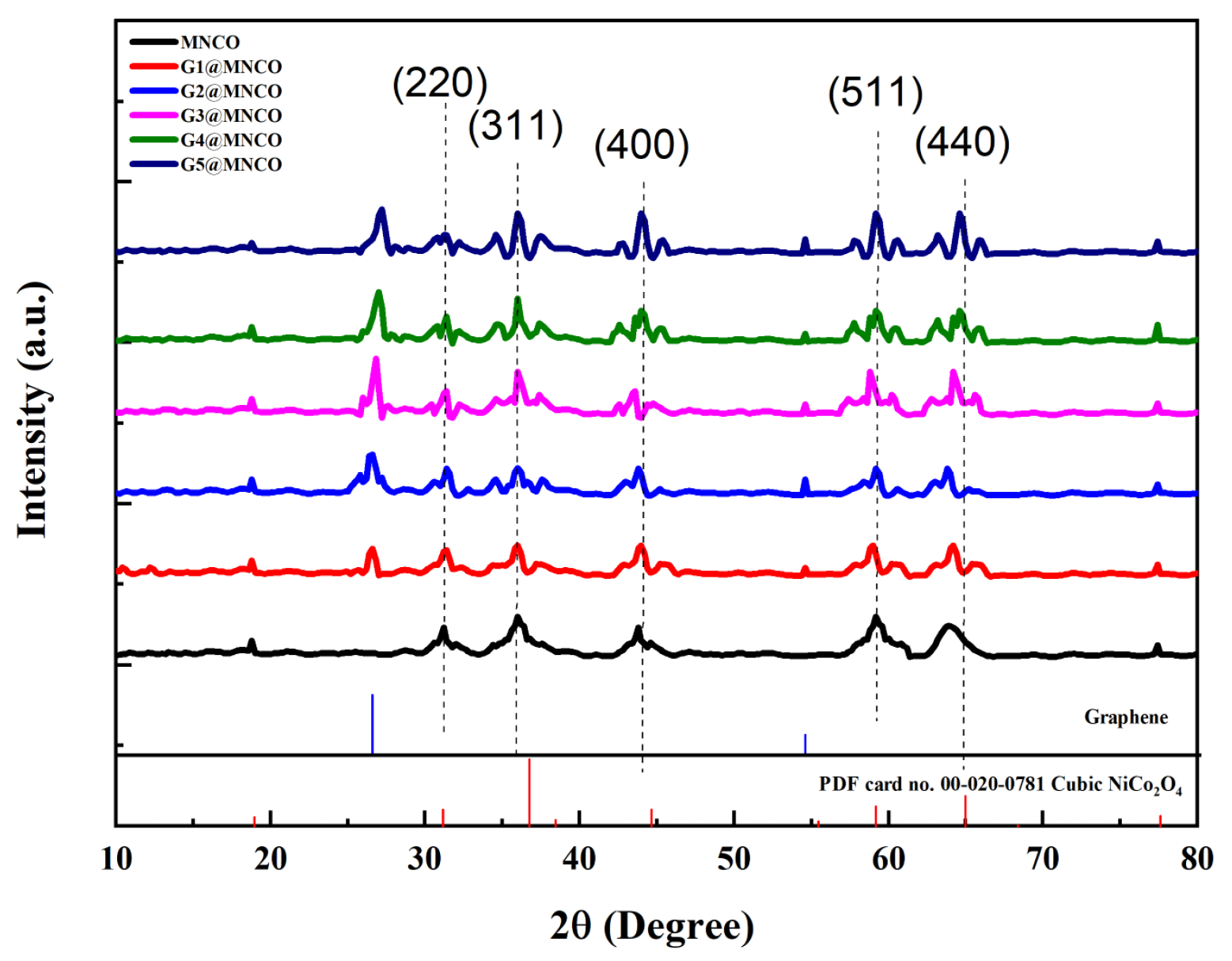
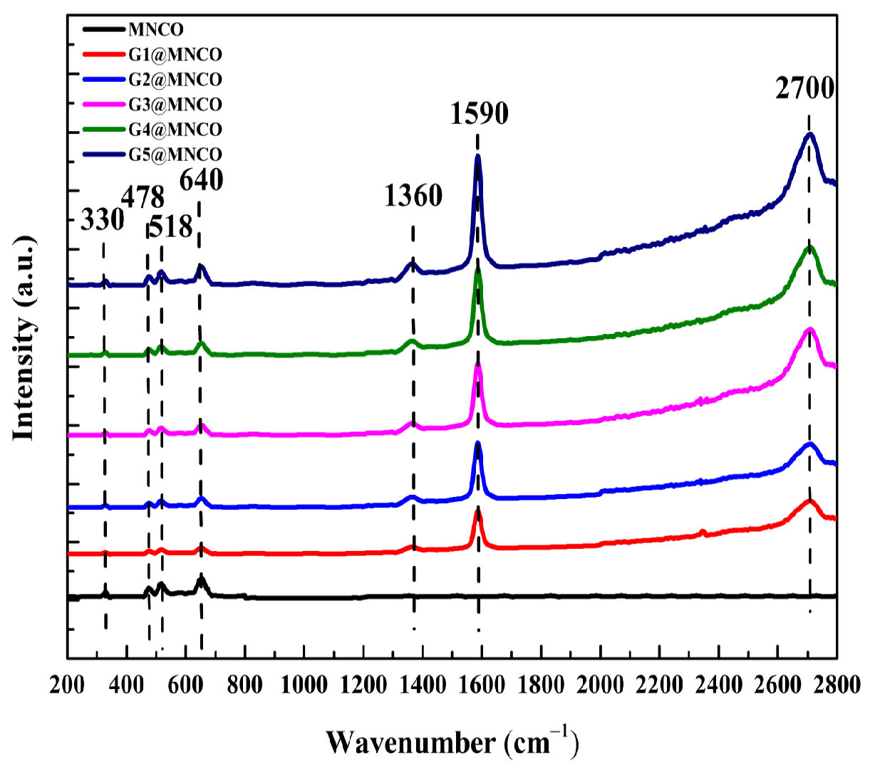
3.1. Crystalline-Phase and Raman Analyses

The X-ray diffraction (XRD) patterns of the G@MNCO electrodes with varying graphene contents are presented in Figure 2. All samples exhibited diffraction peaks corresponding to the spinel NiCo2O4 phase, consistent with the standard pattern (PDF card no. 00-020-0781). Characteristic reflections at the (220), (311), (400), (511), and (440) planes confirmed the successful formation of the crystalline NiCo2O4 structure. Importantly, as the amount of graphene in the G@MNCO electrodes increased, there was a significant enhancement in the intensity of the graphene peaks. The high-valence ion in the main crystal structure was occupied by low valence, leading to a shortage of oxygen ions. The main reason for this is that the number of introduced oxygen ions is lower than the number of cations in the main crystalline structure, causing the oxygen ratio to decrease. The conductivity properties of the oxide solid solution’s intermediate layer will be improved by generating oxygen vacancies in the structure to satisfy the relationship between position and electrical neutrality [16]. Figure 3 shows the Raman spectra of MNCO and G@MNCO. The observed Raman peaks at 330, 478, 515, and 640 cm−1 corresponded to the characteristic peaks of NiCo2O4. No additional phases or impurities were detected. With the increasing graphene content in the G@MNCO electrodes, the intensity of the graphene-related peaks at 1360, 1590, and 2700 cm−1 also increased.

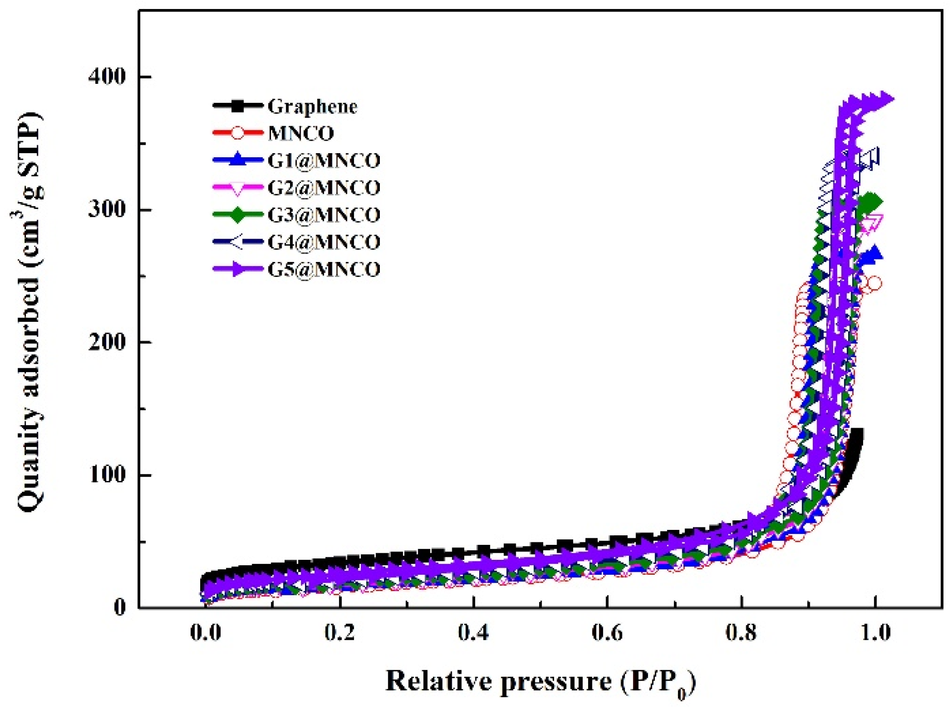
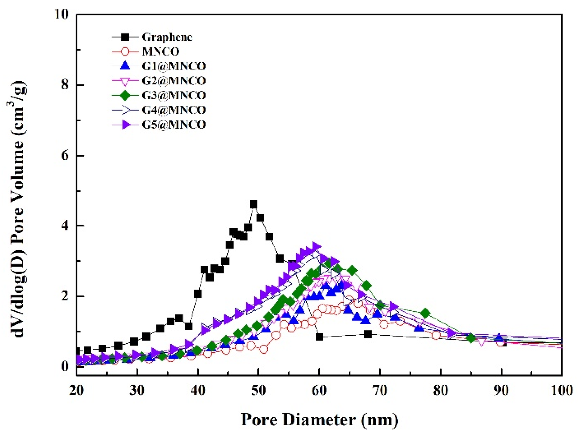
3.2. Characterization of Textural Properties

The nitrogen (N2) adsorption–desorption isotherms of all samples are presented in Figure 4 and Figure 5. All the samples exhibited type IV isotherms with hysteresis loops, confirming that the G@MNCO electrodes possessed a mesoporous structure. All samples exhibited a notable increase in nitrogen uptake at a relative pressure (P/P0) of approximately 0.9, indicating capillary condensation typically associated with mesoporous structures in the N2 adsorption–desorption isotherms. According to a report by Xing et al. [17], the presence of an H2-type hysteresis loop with a steep adsorption profile and a triangular-shaped desorption branch suggests the existence of highly interconnected mesopores with an ink-bottle-like pore geometry. Table 2 details the textural characterization of graphene and the G@MNCO electrodes, revealing that the increase in surface area is attributed to the microstructural transformation from a dense to a porous structure as more graphene is incorporated during the electrodeposition process. As shown in Table 2, the specific surface areas of the samples followed the order of F > E > D > C > B > A. This suggests that the surface area enhancement correlates with the increasing amount of graphene added.

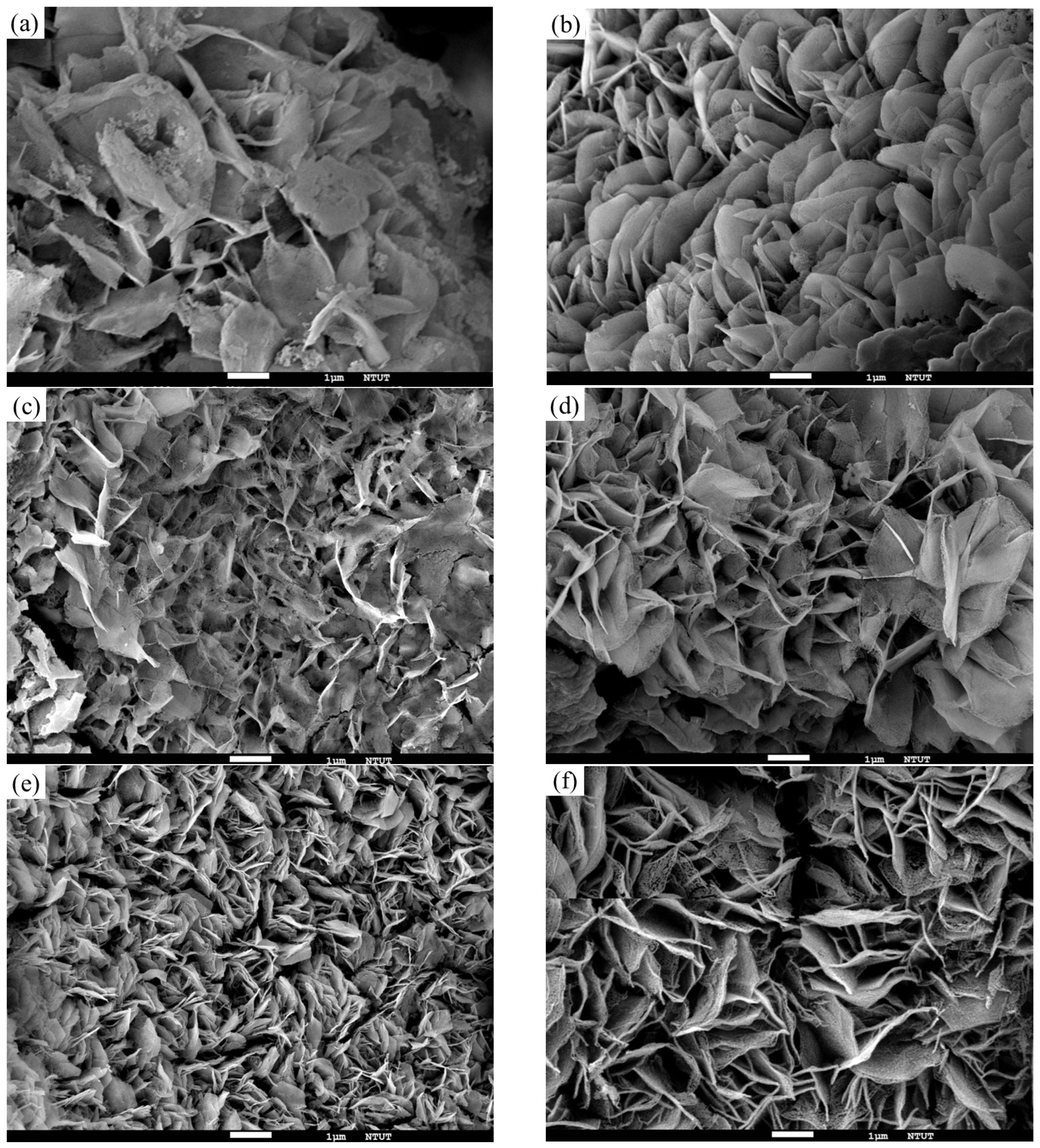
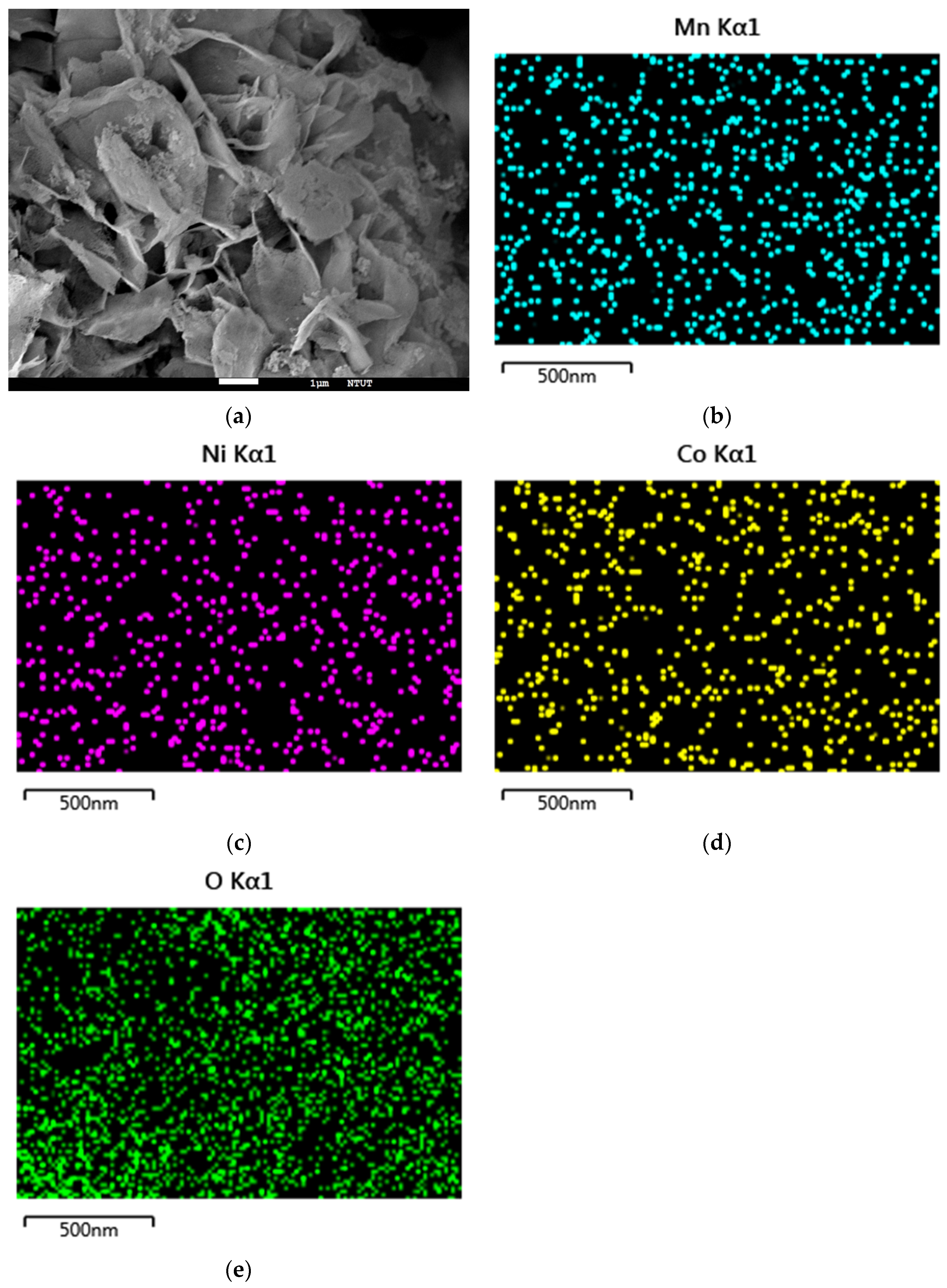
3.3. Morphology Analyses

As depicted in Figure 6a, flake-like structures of NiCo2O4 were observed on the Cu foam substrate. Figure 6b–f illustrate the impact of graphene addition on the microstructure of the G@MNCO composite. With a 2 wt% addition of graphene, the G2@MNCO composite exhibited a flower-like morphology, composed of interconnected petaloid NiCo2O4 micro-flakes (Figure 6c). As the graphene content increased to 5 wt%, the Cu substrate became completely covered with aggregated micro-flakes, forming a leaf-like morphology (Figure 6f). The microstructure of the G@MNCO composites was strongly affected by the amount of graphene added. The SEM mapping results of the G5@MNCO electrode doping distribution of Mn are shown in Figure 7a–e. Figure 7a presents the surface morphology of the G5@MNCO electrode, revealing a crumpled, sheet-like structure with abundant folds and porous features, which may facilitate ion diffusion and increase the electrochemical active surface area. It can be inferred that the element has an excellent doping distribution on the electrode surface. As shown in Table 3, the atomic ratios of Ni:Co:O: Mn in the samples were in the range of 1.00:4.16–4.23:4.90–2.10:0.19–0.021.
As shown in Figure 8a–c, the high-resolution XPS spectra confirmed the coexistence of Mn, Ni, and Co in their respective oxidation states. The Mn 2p spectrum in Figure 8a exhibited two main peaks at 642.3 eV and 653.7 eV, corresponding to Mn 2p3/2 and Mn 2p1/2, respectively. Deconvolution revealed the presence of Mn3+ and Mn4+ states, indicating the mixed-valence nature of manganese within the spinel framework [18]. The Ni 2p spectrum in Figure 8b shows distinct peaks at 855.5 eV (Ni 2p3/2) and 873.1 eV (Ni 2p1/2), which can be deconvoluted into components associated with both Ni2+ and Ni3+ species. The presence of satellite peaks further confirmed the partial oxidation of Ni [19]. Regarding the Co 2p spectrum in Figure 8c, the Co 2p3/2 and Co 2p1/2 peaks appeared at 779.4 eV and 794.6 eV, respectively, and the deconvoluted peaks confirmed the coexistence of Co2+ and Co3+. These observations are consistent with the characteristic features of Co-containing spinel oxides [20]. The atomic ratios of Ni, Co, O, and Mn for each sample, calculated from the XPS survey spectra, are provided in Table 4. The pristine MNCO had a Ni:Co:O: Mn ratio of 1:2.3:5.1:0.038, while a gradual variation in composition was observed with increasing graphene incorporation. For instance, the G1@MNCO sample exhibited a ratio of 1:2.8:4.9:0.041, and this trend continued up to G5@MNCO with 1:2.7:4.1:0.041. Notably, the oxygen content remained high, reflecting the presence of metal–oxygen bonds in the spinel matrix, and the slight increase in Mn content in G@MNCO variants suggested successful co-deposition of Mn into the NiCo2O4 lattice. These atomic distributions further support the successful integration of Mn and confirm the multi-valent nature of Ni, Co, and Mn species, which are beneficial for enhancing redox activity and Faradaic capacitance in pseudocapacitive systems.
The TGA results for the G@MNCO electrodes are presented in Figure 9, showing that the Mn, Ni, and Co materials were completely oxidized at 600 °C. Between 600 °C and 1000 °C, only graphene remained in the sample. From sample MNCO to G5@MNCO, the residual materials after 1000 °C were 0%, 1%, 2%, 3%, 4%, and 5%, respectively. This indicates the presence of graphene in the material in the anticipated proportions.

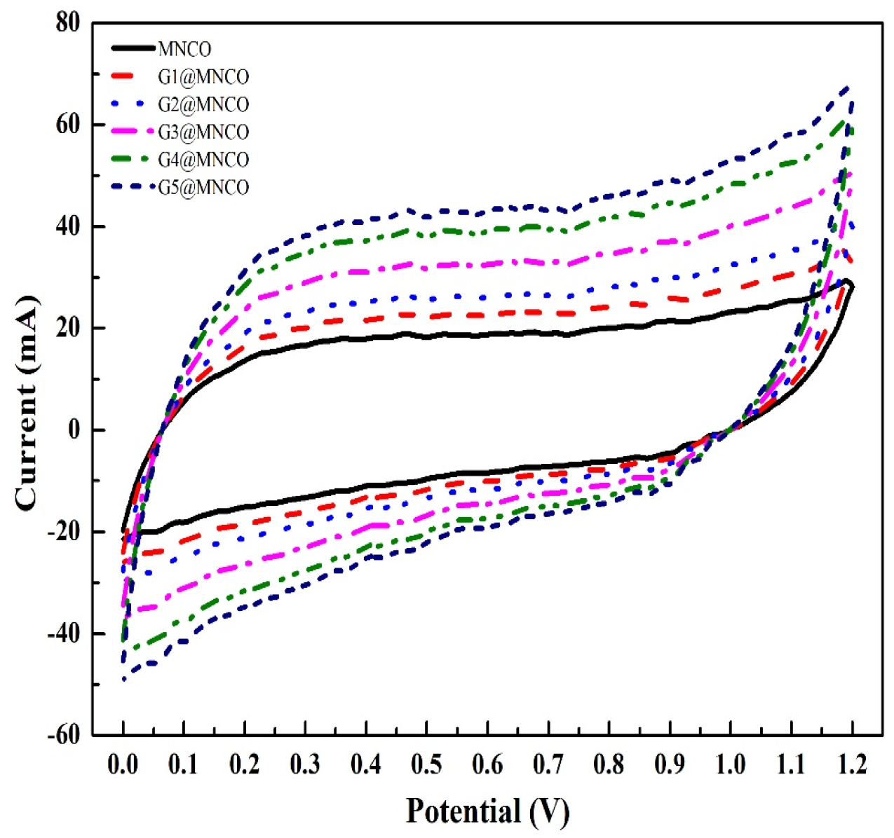
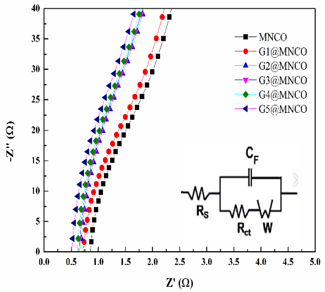
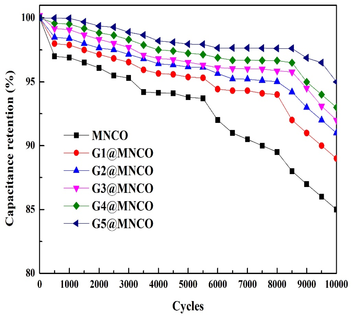
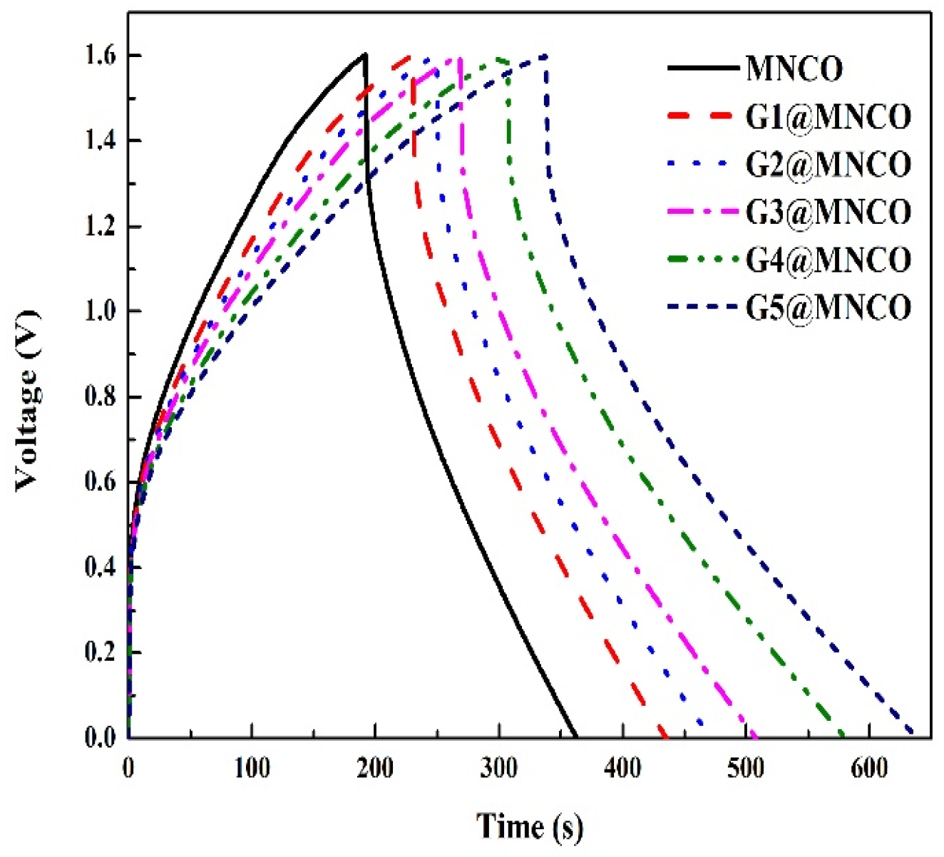
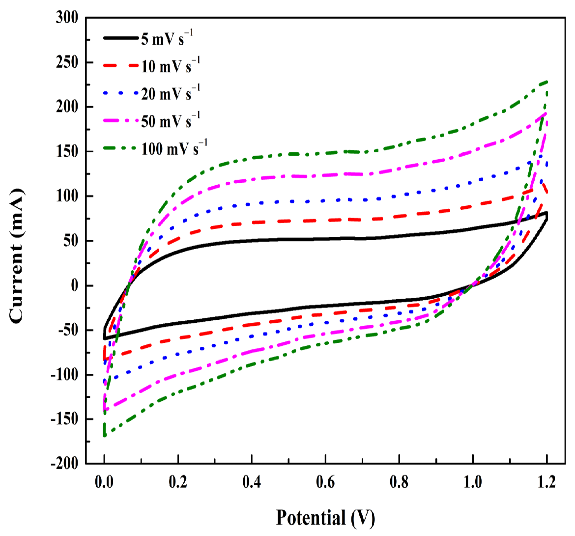
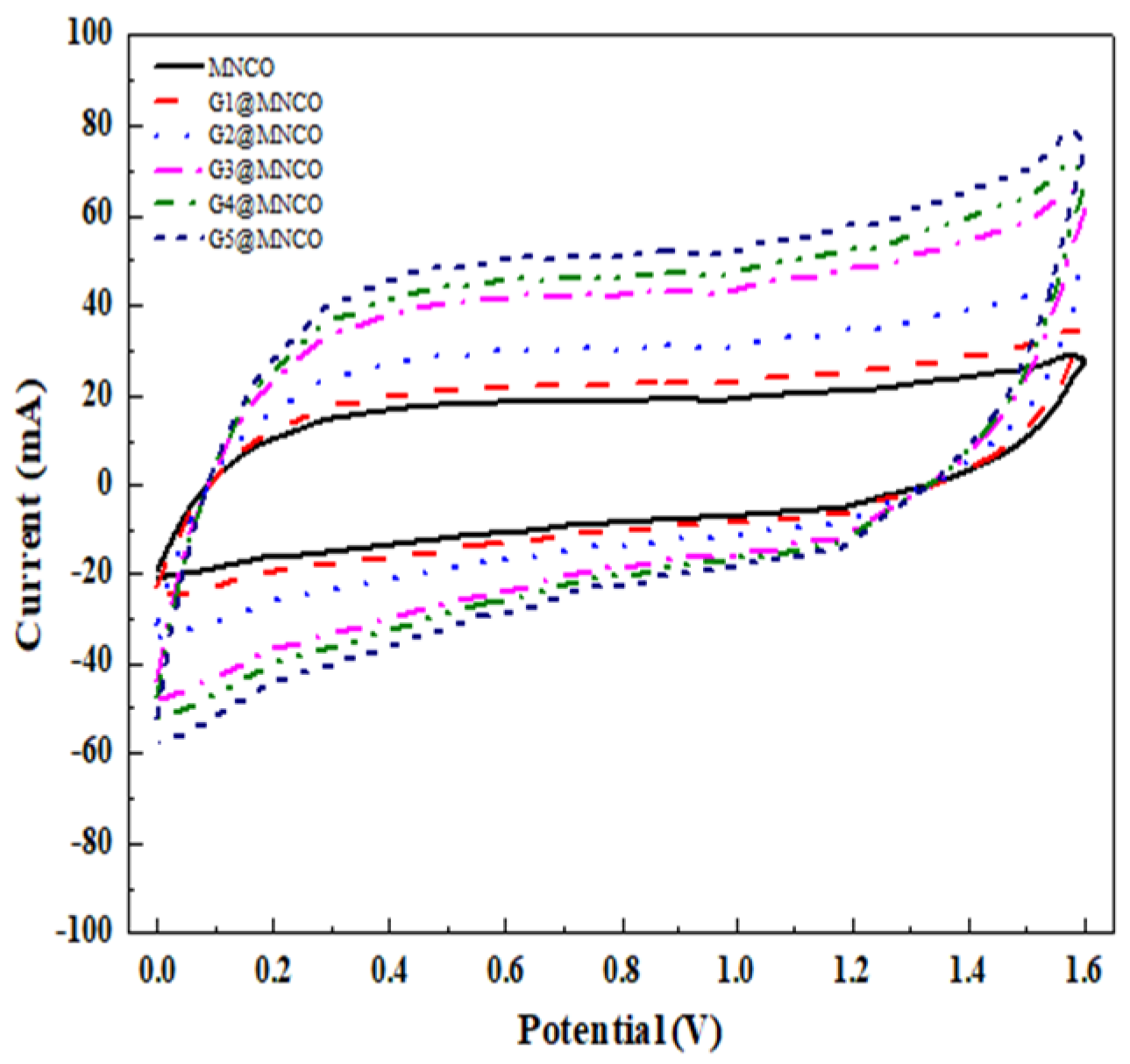
3.4. Electrochemical Performance of G@MNCO Electrodes

Figure 10 and Figure 11 illustrate the findings obtained from the CV and EIS analyses. The specific capacitance of each sample was calculated using the following equation:
C = 1 m v V c V a V a V c I V d V
where C (F/g) represents the specific capacitance, m (g) is the mass of the active electrode material, n (mV s−1) is the scan rate, V c V a   V denotes the potential window, and I (mA) is the current response obtained from the cyclic voltammetry curves. Figure 10 displays the cyclic voltammetry (CV) curves of the samples, demonstrating that increasing the graphene content resulted in a noticeable enlargement of the CV curve area, thereby indicating an improvement in specific capacitance. As summarized in Figure 10, the specific capacitance values for the MNCO to G5@MNCO samples were 310, 352, 400, 431, 451, and 475 F/g, respectively. For Mn, the typical redox reaction involves the transition between Mn(III) and Mn(IV) oxidation states during cycling, which contributes to the pseudocapacitance behavior [21]. Similarly, Ni and Co undergo redox reactions at the electrode surface, with Ni(II)/Ni(III) and Co(II)/Co(III) redox couples, which enhance the charge storage capacity [22,23]. The increase in graphene content in the G@MNCO electrodes facilitates improved conductivity and faster ion diffusion, which, in turn, enhances the Faradaic reactions, further boosting the specific capacitance [24]. Figure 11 illustrates the high-frequency region of the electrochemical impedance spectroscopy (EIS) spectra. The intersection point on the real axis (x-axis) represents the ohmic resistance (Rs), which includes the internal resistance of the electrolyte, the contact resistance at the electrode–electrolyte interface, and the intrinsic resistance of the electrode material. The estimated Rs values for the sample electrodes were 0.82, 0.72, 0.69, 0.64, 0.61, and 0.55 Ω, showing a decreasing trend with increasing graphene content. In the medium-to-high frequency range, the diameter of the semicircular arc corresponds to the charge transfer resistance (Rct, where a smaller arc radius indicates lower faradaic resistance at the interface. At low frequencies, the impedance curves display a linear tail, indicative of Warburg impedance (Ws), which is associated with the diffusion of ions from the electrolyte into the electrode. Notably, the G5@MNCO electrode exhibits a steeper Warburg slope, suggesting reduced ion diffusion resistance, likely due to the improved conductivity and ion transport pathways facilitated by the higher graphene content [25,26,27]. Figure 12 depicts the capacitance retention performance tested over 10,000 times under a 1 A g−1 current density. As shown in Figure 10, the retention rates for MNCO through the G5@MNCO samples were 85%, 89%, 91%, 92%, 93%, and 95%, demonstrating a progressive improvement in capacitance stability with increasing graphene incorporation. According to Figure 13, the G5@MNCO sample had the longest discharge time among all the samples. This improvement can be primarily attributed to the strong interfacial interaction between MNCO and graphene, which enhances structural stability, electronic conductivity, and ion diffusion efficiency [28].
Figure 14 presents the cyclic voltammetry (CV) profiles of the G5@MNCO electrode at various scan rates ranging from 5 to 100 mV/s, measured using a three-electrode configuration. As the scan rate increased, the current response also increased, indicating excellent supercapacitive behavior. Notably, the CV curves retained a quasi-rectangular shape across all scan rates, suggesting fast and reversible redox reactions. This behavior implies that the capacitance of the electrodeposited G5@MNCO electrode arises not only from electric double-layer formation but also from pseudocapacitive contributions, differentiating it from typical EDLCs that exhibit nearly ideal rectangular CV profiles.
To further evaluate the rate capability, the specific capacitance values were calculated based on the CV curves at different scan rates. The electrode exhibited a high specific capacitance of 475 F/g at 5 mV/s, which gradually decreased to 324 F/g at 10 mV/s, 211 F/g at 20 mV/s, 101 F/g at 50 mV/s, and 65 F/g at 100 mV/s. The decreasing trend is attributed to limited ion diffusion and charge transfer resistance at higher scan rates. Nevertheless, the capacitance retention remained notable, with over 44% retained from 5 to 20 mV/s, confirming the excellent rate performance of the G5@MNCO electrode and its suitability for high-rate energy storage applications.
According to Table 5, the G5@MNCO electrode exhibited the highest specific capacitance (202 F/g), the lowest intrinsic resistance (0.55 Ω), and the best capacitance retention (95%) after 10,000 cycles. This enhancement is attributed to the synergistic effect arising from three key features: (1) the nanostructured Mn–Ni–Co oxide matrix, (2) the conductive graphene network, and (3) the direct binder-free growth on Cu foam via ultrasonic-assisted electrodeposition. This combination promotes robust interfacial integration, which significantly improves structural stability and minimizes interfacial charge resistance. Graphene serves as a highly conductive scaffold that enhances electron mobility and provides additional ion-accessible surface area, while Cu foam offers mechanical support and a 3D conductive backbone that reduces overall charge transfer resistance. Furthermore, the enhanced performance is closely related to the formation of oxygen vacancies within the G@MNCO framework. These vacancies, induced during the ultrasonic-assisted deposition process, act as active defect sites that facilitate redox reactions and improve electronic conductivity by introducing localized energy levels near the Fermi level [29,30,31,32]. The presence of oxygen vacancies also promotes greater adsorption and transport of electrolyte ions, contributing to higher charge storage capability [33]. Thus, the improved electrochemical behavior of G5@MNCO is a result of this multi-component synergy, where oxygen vacancies, graphene integration, and conformal electrodeposition on Cu foam collectively enable efficient charge transport, rapid ion diffusion, and stable cycling performance. To further evaluate the practical electrochemical performance, CV measurements of all samples were conducted using a two-electrode configuration at a scan rate of 5 mV/s, as shown in Figure 15. All G@MNCO-based electrodes exhibit quasi-rectangular CV curves, indicating good capacitive behavior and reversible charge–discharge processes in a symmetric device setup.
The specific capacitance values calculated from the CV curves demonstrate a consistent improvement with increasing graphene content. The pristine MNCO electrode yielded a specific capacitance of 195 F/g, while the incorporation of graphene significantly enhanced the charge storage capacity. Specifically, G1@MNCO and G2@MNCO reached 234 F/g and 316 F/g, respectively. With further graphene incorporation, G3@MNCO and G4@MNCO showed higher values of 442 F/g and 482 F/g. Notably, the G5@MNCO electrode achieved the highest specific capacitance of 531 F/g, which represents a 2.7-fold improvement over the unmodified MNCO electrode. These results confirm that the synergistic effect between the conductive graphene network and the redox-active MNCO matrix not only facilitates faster electron/ion transport but also enhances the utilization of active material, making G@MNCO composites highly promising for practical symmetric supercapacitor applications. Table 6 compares the values of this study with the latest literature on similar electrode materials, showing higher capacitance values in this study than in other studies.

4. Conclusions

In this study, G@MNCO thin films were successfully fabricated on copper substrates using a scalable and binder-free ultrasonic-assisted electrodeposition technique. The electrochemical evaluation of the resulting composite electrodes revealed that increasing the graphene content significantly reduced the specific resistance and enhanced the specific capacitance. The incorporation of graphene also contributed to improved surface area, porosity, and oxygen vacancy concentration, which facilitated ion diffusion and Faradaic reactions. Among all compositions, the G5@MNCO electrode exhibited the highest electrochemical performance, confirming the synergistic effect between the conductive graphene network and the redox-active Mn–Ni–Co oxide matrix. The uniform film morphology and enhanced charge transport achieved through ultrasonic cavitation highlight the effectiveness of this fabrication method. Overall, the integration of graphene and spinel-type metal oxides via ultrasonic-assisted electrodeposition presents a practical and energy-efficient route to developing high-performance pseudocapacitive electrodes. The superior conductivity, structural uniformity, and scalable processability demonstrated in this work support its relevance for next-generation energy storage applications.

Author Contributions

Conceptualization, K.-C.L. and G.-T.P.; methodology, T.C.-K.Y.; software, T.C.-K.Y.; validation, G.-T.P., T.J.T. and C.-M.H.; formal analysis, G.-T.P.; investigation, P.-C.S. and G.-T.P.; resources, A.N.N.; data curation, C.-M.H.; writing—original draft preparation, K.-C.L.; writing—review and editing, G.-T.P., C.-M.H. and K.L.P.; visualization, K.L.P.; supervision, G.-T.P., T.J.T. and C.-M.H.; project administration, G.-T.P.; funding acquisition, G.-T.P. All authors have read and agreed to the published version of the manuscript.

Funding

This work was financially supported by the National Science and Technology Council (NSTC) of Taiwan under project NSTC 113-2637-E-168-002. The authors gratefully acknowledge the use of code XRD005100 and use of the machine equipment belonging to the Core Facility Center of National Cheng Kung University.

Data Availability Statement

Data is contained within the article.

Conflicts of Interest

The authors declare no conflicts of interest.

References

  1. Yun, Y.S.; Park, H.H.; Jin, H.-J. Pseudocapacitive effects of N-doped carbon nanotube electrodes in supercapacitors. Materials 2012, 5, 1258–1266. [Google Scholar] [CrossRef]
  2. Lee, H.-M.; Lee, K.; Kim, C.-K. Electrodeposition of manganese-nickel oxide films on a graphite sheet for electrochemical capacitor applications. Materials 2014, 7, 265–274. [Google Scholar] [CrossRef] [PubMed]
  3. Kim, B.K.; Chabot, V.; Yu, A. Carbon nanomaterials supported Ni(OH)2/NiO hybrid flower structure for supercapacitor. Electrochim. Acta 2013, 109, 370–380. [Google Scholar] [CrossRef]
  4. Pan, H.; Li, J.; Feng, Y. Carbon nanotubes for supercapacitor. Nanoscale Res. Lett. 2010, 5, 654–668. [Google Scholar] [CrossRef]
  5. Shinde, S.; Jalak, M.; Ghodake, G.; Maile, N.; Kumbhar, V.; Lee, D.; Fulari, V.; Kim, D.-Y. Chemically synthesized nanoflakes-like NiCo2S4 electrodes for high-performance supercapacitor application. Appl. Surf. Sci. 2019, 466, 822–829. [Google Scholar] [CrossRef]
  6. Deng, B.; Luong, D.X.; Wang, Z.; Kittrell, C.; McHugh, E.A.; Tour, J.M. Urban mining by flash Joule heating. Nat. Commun. 2021, 12, 5794. [Google Scholar] [CrossRef]
  7. Liu, Y.; Zhou, Z.; Zhang, S.; Luo, W.; Zhang, G. Controllable synthesis of CuS hollow microflowers hierarchical structures for asymmetric supercapacitors. Appl. Surf. Sci. 2018, 442, 711–719. [Google Scholar] [CrossRef]
  8. Patil, D.S.; Pawar, S.A.; Shin, J.C. Core-shell structure of Co3O4@ CdS for high performance electrochemical supercapacitor. Chem. Eng. J. 2018, 335, 693–702. [Google Scholar] [CrossRef]
  9. He, Y.-L.; Xu, R.-D.; He, S.-W.; Chen, H.-S.; Li, K.; Zhu, Y.; Shen, Q.-F. Effect of NaNO3 concentration on anodic electrochemical behavior on the Sb surface in NaOH solution. Int. J. Miner. Metall. Mater. 2018, 25, 288–299. [Google Scholar] [CrossRef]
  10. Wang, Y.; Guo, J.; Wang, T.; Shao, J.; Wang, D.; Yang, Y.-W. Mesoporous transition metal oxides for supercapacitors. Nanomaterials 2015, 5, 1667–1689. [Google Scholar] [CrossRef]
  11. Zhang, H.; Wang, J.; Chen, S.; Wang, H.; He, Y.; Ma, C. Ni–SiC composite coatings with improved wear and corrosion resistance synthesized via ultrasonic electrodeposition. Ceram. Int. 2021, 47, 9437–9446. [Google Scholar] [CrossRef]
  12. Devendra, B.K.; Praveen, B.; Tripathi, V.; Nagaraju, G.; Prasanna, B.; Shashank, M. Development of rhodium coatings by electrodeposition for photocatalytic dye degradation. Vacuum 2022, 205, 111460. [Google Scholar] [CrossRef]
  13. Yu, Y.; Li, Y.; Zhong, Y.; Wang, M.; Guo, Z. Ultrasound-Assisted Electrodeposition of Fe-Ni-Co Ternary Alloy Film: Microstructure, Corrosion Resistance, and Soft Magnetic Property. JOM 2024, 76, 4987–4997. [Google Scholar] [CrossRef]
  14. Costa, J.M.; De Almeida Neto, A.F.D. Ultrasound-assisted electrodeposition and synthesis of alloys and composite materials: A review. Ultrason. Sonochemistry 2020, 68, 105193–105204. [Google Scholar] [CrossRef]
  15. Liu, B.; Mei, T.; Chu, H.; Wang, J.; Du, S.; Miao, Y.; Zhang, W. Ultrasonic-assisted electrodeposition of Ni/diamond composite coatings and its structure and electrochemical properties. Ultrason. Sonochemistry 2021, 73, 105475–705485. [Google Scholar] [CrossRef]
  16. Li, S.; Zhao, X.; Feng, Y.; Yang, L.; Shi, X.; Xu, P.; Zhang, J.; Wang, P.; Wang, M.; Che, R. A flexible film toward high-performance lithium storage: Designing nanosheet-assembled hollow single-hole Ni–Co–Mn–O spheres with oxygen vacancy embedded in 3D carbon nanotube/graphene network. Small 2019, 15, 1901343. [Google Scholar] [CrossRef]
  17. Ahmad, F.; Zahid, M.; Jamil, H.; Khan, M.A.; Atiq, S.; Bibi, M.; Shahbaz, K.; Adnan, M.; Danish, M.; Rasheed, F. Advances in graphene-based electrode materials for high-performance supercapacitors: A review. J. Energy Storage 2023, 72, 108731. [Google Scholar] [CrossRef]
  18. Nesbitt, H.W.; Banerjee, D. Interpretation of XPS Mn(2p) spectra of Mn oxyhydroxides and constraints on the mechanism of MnO2 precipitation. Am. Mineral. 1998, 83, 305–315. [Google Scholar] [CrossRef]
  19. Biju, V. Ni 2p X-ray photoelectron spectroscopy study of nanostructured nickel oxide. Mater. Res. Bull. 2007, 42, 791–796. [Google Scholar] [CrossRef]
  20. Zhao, L.; Wang, L.; Yu, P.; Tian, C.; Feng, H.; Diao, Z.; Fu, H. Hierarchical porous NiCo2O4 nanosheet arrays directly grown on carbon cloth with superior lithium storage performance. Dalton Trans. 2017, 46, 4717–4723. [Google Scholar] [CrossRef]
  21. Chiku, M.; Abdollahifar, M.; Crosnier, O.; Dunn, B.; Brousse, T.; Fic, K.; Maćkowiak, A.; Okubo, M.; Naoi, K.; Ogihara, N.; et al. Redox Materials for Electrochemical Capacitors. Electrochemistry 2024, 92, 074002–074021. [Google Scholar] [CrossRef]
  22. Wang, H.; Casalongue, H.S.; Liang, Y.; Dai, H. Ni(OH)2 Nanoplates Grown on Graphene as AdvancedElectrochemical Pseudocapacitor Materials. J. Am. Chem. Soc. 2010, 132, 7231–7558. [Google Scholar]
  23. Guan, J.; Liu, M.; Zhu, L.; Wang, J.; Han, Q.; Yang, X.; Hua, W.; Xie, L.; Cao, X. Ni/Co bimetallic organic frameworks nanospheres for high-performance electrochemical energy storage. Nano Res. 2024, 17, 5122–5130. [Google Scholar] [CrossRef]
  24. Zhang, M.; Liu, W.; Liang, R.; Tjandra, R.; Yu, A. Graphene quantum dot induced tunable growth of nanostructured MnCo2O4.5 composites for high-performance supercapacitors. Sustain. Energy Fuels 2019, 3, 2499–2508. [Google Scholar] [CrossRef]
  25. Chung, H.-Y.; Pan, G.-T.; Hong, Z.-Y.; Hsu, C.-T.; Chong, S.; Yang, T.C.-K.; Huang, C.-M. Biomass-derived porous carbons derived from soybean residues for high performance solid state supercapacitors. Molecules 2020, 25, 4050. [Google Scholar] [CrossRef]
  26. Chen, G.; Yang, G.; He, C.; Lan, T.; He, S.; Yang, H.; Liu, L.; Yang, W.; Jian, S.; Zhang, Q. High Capacitive Performance of N, O-Codoped Carbon Aerogels Synthesized via a One-Step Chemical Blowing and In Situ Activation Process. Langmuir 2024, 40, 19944–19953. [Google Scholar] [CrossRef]
  27. Zhu, Z.; Zhao, X.; Xia, B.Y.; You, B. Efficient Noble-Metal-Free Integration Electrolysis for Solar H2 and Supercapacitor Electrode Coproduction in Acidic Water. ChemSusChem 2024, 17, e202301213. [Google Scholar] [CrossRef]
  28. Su, M.; Wang, Z.; Guo, H.; Li, X.; Huang, S.; Xiao, W.; Gan, L. Enhancement of the Cyclability of a Si/Graphite@ Graphene composite as anode for Lithium-ion batteries. Electrochim. Acta 2014, 116, 230–236. [Google Scholar] [CrossRef]
  29. Pacchioni, G. Oxygen Vacancy: The Invisible Agent on Oxide Surfaces. ChemPhyChem 2003, 4, 1041–1047. [Google Scholar] [CrossRef]
  30. Zhu, K.; Shi, F.; Zhu, X.; Yang, W. The roles of oxygen vacancies in electrocatalytic oxygen evolution reaction. Nano Energy 2020, 73, 104761–104778. [Google Scholar] [CrossRef]
  31. Wang, Y.; Zhang, Y.; Gao, G.; Fan, Y.; Wang, R.; Feng, J.; Yang, L.; Meng, A.; Zhao, J.; Li, Z. Effectively modulating oxygen vacancies in flower-like δ-MnO2 nanostructures for large capacity and high-rate zinc-ion storage. Nano-Micro Lett. 2023, 15, 219. [Google Scholar] [CrossRef] [PubMed]
  32. Saleh, A.A.; Amer, A.; Sayed, D.M.; Allam, N.K. A facile electrosynthesis approach of Mn-Ni-Co ternary phosphides as binder-free active electrode materials for high-performance electrochemical supercapacitors. Electrochim. Acta 2021, 380, 138197. [Google Scholar] [CrossRef]
  33. Du, C.; Shi, S.; Chen, G.; Zhang, Y.; Wei, Q.; Li, L.; Wan, G.; Deng, Z.; Wu, Y.; Su, Y. Structurally stable Fe–Ni–Co phosphide/graphene and nitrogen-doped carbon/graphene constructed by atomic layer deposition for high-performance hybrid supercapacitor. Mater. Today Energy 2023, 34, 101287. [Google Scholar] [CrossRef]
  34. Li, X.; Lin, Z.; Wang, C.; Wang, H.; Feng, S.; Li, T.; Ma, Y. Hierarchical graphene oxide/manganese dioxide/cobalt-nickel layered double hydroxide electrodes for high energy density asymmetric flexible supercapacitor. Chem. Eng. J. 2024, 484, 149430. [Google Scholar] [CrossRef]
Figure 1. Deposition method of Gx@MNCO electrodes, with x = 1, 2, 3, 4, and 5 wt% graphene.
Surfaces 08 00043 g001
Figure 2. XRD patterns of MNCO and G@MNCO electrodes.
Surfaces 08 00043 g002
Figure 3. Raman spectra of MNCO and G@MNCO electrodes.
Surfaces 08 00043 g003
Figure 4. Hysteresis loop of MNCO and G@MNCO electrodes between N2 adsorption and desorption isotherms.
Surfaces 08 00043 g004
Figure 5. Pore size distribution of MNCO and G@MNCO electrodes.
Surfaces 08 00043 g005
Figure 6. Microstructures of (a) MNCO, (b) G1@MNCO, (c) G2@MNCO, (d) G3@MNCO, (e) G4@MNCO, and (f) G5@MNCO electrodes.
Surfaces 08 00043 g006
Figure 7. (a) the surface morphology of the G5@MNCO electrode. SEM elemental mapping images of the G5@MNCO electrode showing the uniform distribution of (b) Mn, (c) Ni, (d) Co, and (e) O elements.
Surfaces 08 00043 g007
Figure 8. XPS spectra of (a) Mn 2p, (b) Ni 2p, and (c) Co 2p of the G5@MNCO electrode.
Surfaces 08 00043 g008
Figure 9. TGA of G@MNCO electrodes.
Surfaces 08 00043 g009
Figure 10. Cyclic voltammograms of MNCO and G@MNCO electrodes.
Surfaces 08 00043 g010
Figure 11. Nyquist plots of MNCO and G@MNCO electrodes.
Surfaces 08 00043 g011
Figure 12. Capacitance retention of G@MNCO electrodes.
Surfaces 08 00043 g012
Figure 13. GCD of MNCO and G@MNCO electrodes.
Surfaces 08 00043 g013
Figure 14. Cyclic voltammetry curves of the G5@MNCO electrode at various scan rates.
Surfaces 08 00043 g014
Figure 15. CV profile of the two-electrode device under 5 mV/s.
Surfaces 08 00043 g015
Table 1. Synthesis parameters.
SamplesMole Ratios of Ni:Co:MnpH ValueGraphene (wt%)Annealed Temperature (°C)
MNCO1:1:170500
G1@MNCO1:1:171500
G2@MNCO1:1:172500
G3@MNCO1:1:173500
G4@MNCO1:1:174500
G5@MNCO1:1:175500
Table 2. Textural properties of MNCO and G@MNCO electrodes.
SampleSurface Area (m2/g)Pore Volume
(cm3/g)
Pore Size
(Å)
Graphene513.28 ± 2.51.45 ± 0.036.76 ± 2
MNCO112.45 ± 2.10.82 ± 0.02157 ± 3
G1@MNCO119.19 ± 2.10.84 ± 0.02160 ± 3
G2@MNCO126.34 ± 2.20.86 ± 0.02163 ± 3
G3@MNCO133.92 ± 2.30.89 ± 0.02166 ± 3
G4@MNCO141.96 ± 2.40.92 ± 0.03169 ± 3
G5@MNCO150.48 ± 2.50.95 ± 0.03173 ± 4
Table 3. Molar and atomic ratios of Ni, Co, O, and Mn in the samples as determined by EDX analysis.
SampleMole Ratios of Ni:Co:MnAtomic Ratios of [Ni]/[Co]/[O]/[Mn]
MNCO1:1:11:4.16:4.9:0.019
G1@MNCO1:1:11:4.12:3.8:0.019
G2@MNCO1:1:11:4.31:3.1:0.016
G3@MNCO1:1:11:4.14:2.8:0.017
G4@MNCO1:1:11:4.11:2.5:0.016
G5@MNCO1:1:11:4.23:2.1:0.021
Table 4. Atomic ratios of Ni, Co, O, and Mn in the samples based on XPS analysis.
SampleAtomic Ratios of [Ni]/[Co]/[O]/[Mn]
MNCO1:2.3:5.1:0.038
G1@MNCO1:2.8:4.9:0.041
G2@MNCO1:2.1:4.1:0.046
G3@MNCO1:2.4:3.9:0.042
G4@MNCO1:3.1:4.2:0.043
G5@MNCO1:2.7:4.1:0.041
Table 5. Specific capacitance values from GCD and intrinsic resistance of samples.
SamplesSpecific Capacitance (F/g)Intrinsic Resistance Electrode (Ω)Capacitance Retention After 10,000-Cycle Test
MNCO1030.8285%
G1@MNCO1320.7289%
G2@MNCO1510.6991%
G3@MNCO1680.6492%
G4@MNCO1820.6193%
G5@MNCO2020.5595%
Table 6. Comparison of specific capacitance between this study and other studies.
Material UsedSynthesis MethodSpecific Capacitance F/gScan Rate/Current DensityRef.
MnNiCo/grapheneElectrochemical deposition5315 mV/sThis work
Ternary metallic nickel–cobalt–manganese phosphidesElectrochemical deposition1771 A/g[32]
FeNiCoP/rGOAtomic layer deposition2401 A/g[33]
Hierarchical graphene oxide/manganese dioxide/cobalt–nickelDrip coating method1631 A/g[34]
Disclaimer/Publisher’s Note: The statements, opinions and data contained in all publications are solely those of the individual author(s) and contributor(s) and not of MDPI and/or the editor(s). MDPI and/or the editor(s) disclaim responsibility for any injury to people or property resulting from any ideas, methods, instructions or products referred to in the content.

