Article

Fabrication of Electroplated Nickel Composite Films Using Cellulose Nanofibers Introduced with Carboxy Groups as Co-Deposited Materials

1
Division of Mechanical Science and Technology, Graduate School of Science and Technology, Gunma University, Kiryu 376-8515, Japan
2
Technical Services Division, Department of Science and Technology, Gunma University, Kiryu 376-8515, Japan
3
Center for Instrumental Analysis, Organization to Promote Research and University-Industry Collaboration, Gunma University, Kiryu 376-8515, Japan
*
Author to whom correspondence should be addressed.
Surfaces 2023, 6(2), 164-178; https://doi.org/10.3390/surfaces6020012
Submission received: 3 April 2023 / Revised: 16 May 2023 / Accepted: 17 May 2023 / Published: 19 May 2023

Abstract

:
In this study, the fabrication of nickel (Ni)-cellulose nanofiber (CNF) composite electroplating films was attempted using sodium carboxymethyl cellulose (CMC) and 2,2,6,6-tetramethylpiperidine 1-oxyl (TEMPO)-oxidized CNF as CNF introduced with carboxy groups. As a result, co-deposition was confirmed for both CNFs, and the former showed 82% improvement in surface Vickers hardness compared to the plated film deposited from a conventional Watts bath without CNF. Although the latter showed slightly inferior 71% improvement, the surface roughness measurement showed a smoother surface than that of the plated copper material C1100. On the other hand, the film with CMC had a rough surface. The image analysis showed that the distance between co-deposited CNF on the surface of the plated film was 40% shorter on the specimen with TEMPO CNF than CMC, indicating that a fine dispersion was obtained. In addition, a co-deposition model was proposed in which Ni is deposited from the chelate complex formed between the carboxylate of CNF and Ni ions. CNF is fixed to the plated film surface by Ni deposition and the simultaneous bond of hydrogen ions to the carboxylate, resulting in a return to the carboxy group.

1. Introduction

In recent years, as international interest in global environmental protection has grown, the efficient use of biomass materials such as wood, which is a renewable resource, has been promoted [1,2,3]. Cellulose fiber (CF) is obtained from wood pulp and it is expected to be used effectively, and especially, cellulose nanofiber (CNF), which is obtained from defibrillated CF into nanoscale fibers, has 1/5 the density and five times the strength of steel [4,5]. Therefore, the industrial use of CNF has been increasing in the automotive and electronics fields for applications such as composite materials [4,6,7,8]. Actually, the searched number using the Lens website (www.lens.org (accessed on 3 April 2023)), an online patent and scholarly literature search service, of published journal articles with “nanocellulose” as a keyword increased approximately 16 times in 2020 compared to 2010, and the number of patents filed and granted increased approximately 23 times [9]. This fact quantitatively represents the growing interest in the industrial use of CNF. Given these facts, we have been conducting research on a composite CNF with an electroplated nickel (Ni) film which is widely used in industry in order to provide higher performance than the conventional one, and to obtain new functionalities such as the improvement of wear resistance, the reduction and inhibition effects of thermal stress, and the formation of a brittle intermetallic compound (IMC) at the solder/electrode interface when composite plating is applied to surface treatment of the electrode [10]. It is reported that excessive production of IMC degrades the reliability of lead-free solder joints [11,12], which is compliant with the restriction of hazardous substances directive (RoHS). Furthermore, it is estimated that approximately 23% of the world’s energy consumption is derived from friction [13]; thus, the development of further wear-resistant coatings is a very important issue to address in order to reduce resource and economic losses [13,14,15].
In the Ni-CNF composite electroplated film obtained in the previous study [10], CNF was not homogeneously dispersed in the Ni film but concentrated only on the side of the plated material, and the used CNF was not chemically modified with the introduced carboxy groups. This prevented the expected functionalities. The cause of this phenomenon was considered to originate from the stainless steel (JIS SUS304) used as the plated material, and there was room for reconsideration of the plating mechanism, including the co-deposition process. Therefore, in this study, the plated material was chosen to be copper (Cu); JIS C1100, which is widely used as an electrode material, was used as the plated material. CNFs introduced with carboxy groups including carboxymethyl cellulose and 2,2,6,6-tetramethylpiperidine 1-oxyl (TEMPO)-oxidized CNFs were applied as a co-deposited material. Carboxymethyl cellulose is an organic polymer that is generally and widely used today as a thickener, binder, and emulsifier in such fields as food additives, pharmaceuticals, cosmetics, and paints due to its low cost and non-toxic properties [16,17]. The process for creating TEMPO-oxidized CNF was discovered by T. Saito et al. between 2004–2006 [18,19,20], and is characterized by the ability to obtain a very finely defibrillated CNF without losing physical properties. Composite polymer materials using TEMPO-oxidized CNFs have excellent transparency, strength, thermal stability, and gas barrier properties, and are expected to be utilized in the electronics, medical, and packaging fields [21,22,23]. When CNFs with carboxy groups are added to water, they change to negatively charged carboxylates, and the mutual electrostatic repulsion between CNFs prevents aggregation, resulting in favorable dispersion properties [24]. Therefore, fine dispersion in the plating solution is expected to promote fine, dense, and homogeneous co-deposition of CNF into the composite plating film and it is believed that the comparison between carboxymethyl cellulose and TEMPO-oxidized CNF, i.e., conventional and newer cellulose materials with carboxy groups is important for the development of CNF-composited functional electroplated film.
Based on the above, in order to obtain homogeneous CNF co-deposition in electroplated Ni films and to elucidate the deposition mechanism, the purpose of this study was to investigate the effects of carboxy groups introduced to CNF on Ni-CNF composite electroplated films.

2. Experimental Procedure

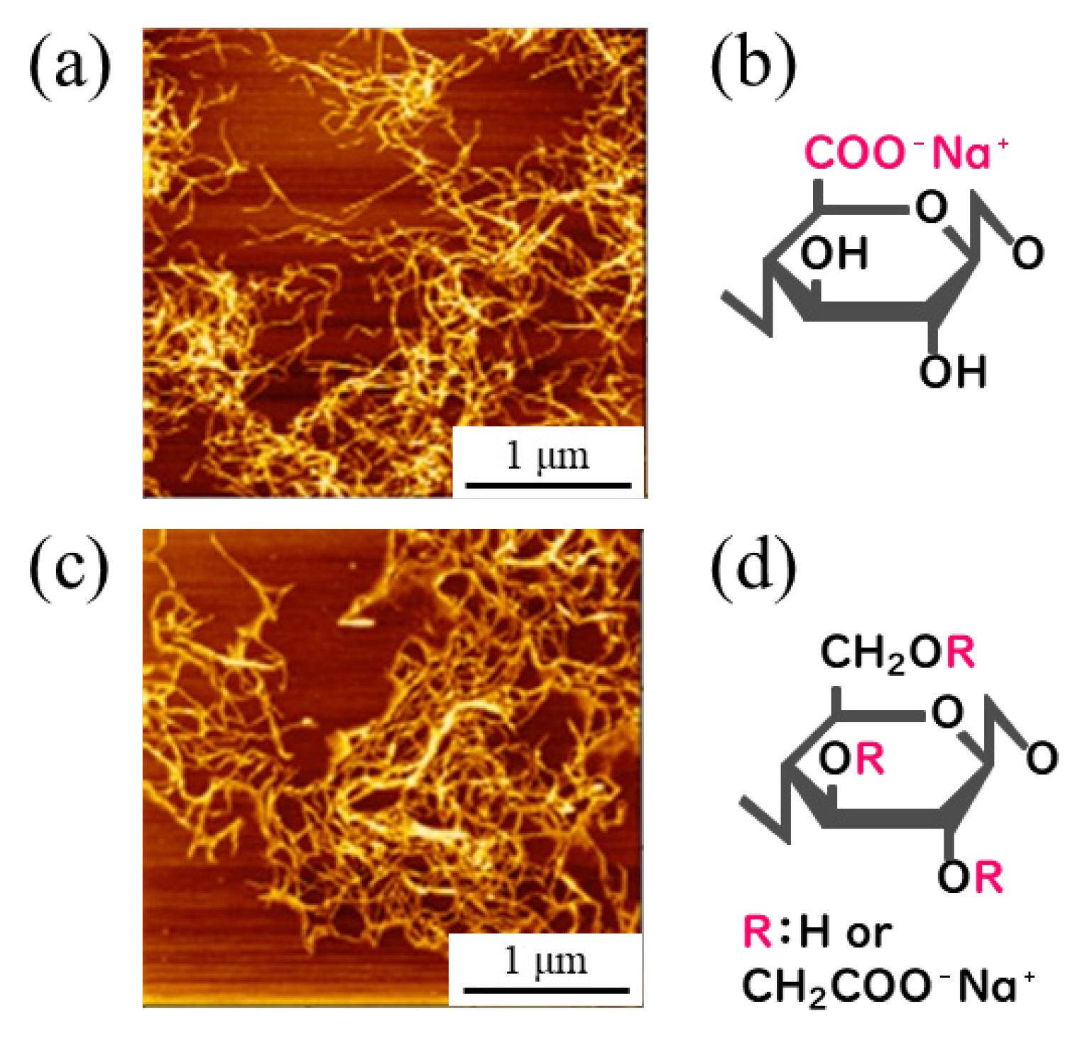
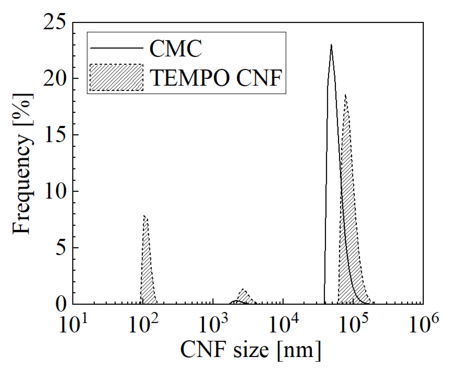
2.1. Preparing Sample Materials

Cu plates (JIS C1100-1/4H, 10 × 10 × 0.3 mm) with a purity of higher than 99.9 mass% were used as the plated material. Before plating, the plated materials were degreased by ultrasonic cleaning with acetone and acid-cleaned with hydrochloric acid (30–35 mass% HCl aq, R.T.).
Two types of CNFs were prepared as co-deposited material to be added to the plating solution: sodium carboxymethyl cellulose (CS-01C, Nippon Paper Industries, Chiyoda-ku, CMC) powder and TEMPO-oxidized CNF (TC-01A, Nippon Paper Industries, Chiyoda-ku, 1.1 mass% gel, TEMPO CNF). CMC and TEMPO CNF have carboxymethyl and carboxy groups introduced as sodium salts, and the representative fiber diameters according to the manufacturer are approximately 2–4 nm and several nm-several hundred nm [25], respectively. Figure 1 shows their representative atomic force microscopy (AFM) images and structural formulas [25].
All reagents used for the plating solution were obtained from FUJIFILM Wako Pure Chemical, Osaka; nickel(II) sulfate hexahydrate (148-01175, NiSO4·6H2O, more than 99 mass% purity), nickel(II) chloride (145-01065, NiCl2, more than 95 mass% purity), and boric acid (021-02195, H3BO3, more than 99.5 mass% purity).

2.2. Plating Process

The solution, whose composition is a typical Watts bath [26] shown in Table 1, was prepared. CNF was added to it as a co-deposited material at a concentration of 1 g/L, and this was used as the plating solution. After the addition of CNF, the plating solution was pre-stirred with a magnetic stirrer to ensure sufficient dispersion. For comparison, plating was also performed under conditions without the addition of CNF. The plating process was conducted in a 200 mL beaker on a magnetic stirrer with a hot plate function. The conditions of the plating solution were set at 50 °C and 200 mL volume. The size distribution of the suspended CNF was measured by the dynamic light scattering (DLS) method after pre-stirring for the used plating solutions, and is shown in Figure 2.
The plating process proceeded with a DC power supply under constant current control, and the current conditions were 2.5 A/dm2 and 3000 C/dm2, i.e., 20 min of plating time. Agitation was constantly applied with a magnetic stirrer. The size of the stirring bar was φ8 × 38 mm, and the rotation speed was set at 300 rpm. The anode was a Ni rod with a purity of higher than 99 mass% (immersed part dimensions φ6 × 50 mm) and the cathode was C1100, the plated material, with the distance between the electrodes set at approximately 50 mm. The plated material was placed in the plating solution so that a 10 × 10 mm plane was perpendicular to the direction of the agitation flow, as shown in Figure 3. Hereinafter, unless otherwise specified, the surface of the plated film in the experimental results refers to the side of the plane that is facing the agitation flow (Figure 3, A side). After plating, the plated specimens were washed with distilled water.

2.3. Analyzing Process

2.3.1. Observation of Plated Film

Optical, secondary electron (SE), and elemental mapping images were observed on the surface and cross section of the obtained plated specimens.
The surface appearance of the plated specimen as obtained was photographed with a digital camera. SE images were also observed by an electron probe micro analyzer (EPMA). In this study, all of the following image observations or analyses using the EPMA were performed at an acceleration voltage of 15 kV.
Specimens for observation of the cross-section of plated films were prepared by the following procedure. The plated films placed in the mold were poured with two-component epoxy resin, cured, cut, and mechanically wet-polished with tap water step by step with #320–#4000 (European FEPA) emery paper. Then, a conductive coat of osmium of approximately 5 nm on the cross-section was formed by an osmium plasma coater (HPC-1SW, Shinku Device) for observation by the EPMA to prevent a charge up. SE image observation and elemental mapping analysis were performed on the obtained cross-section of the plated film by the EPMA.

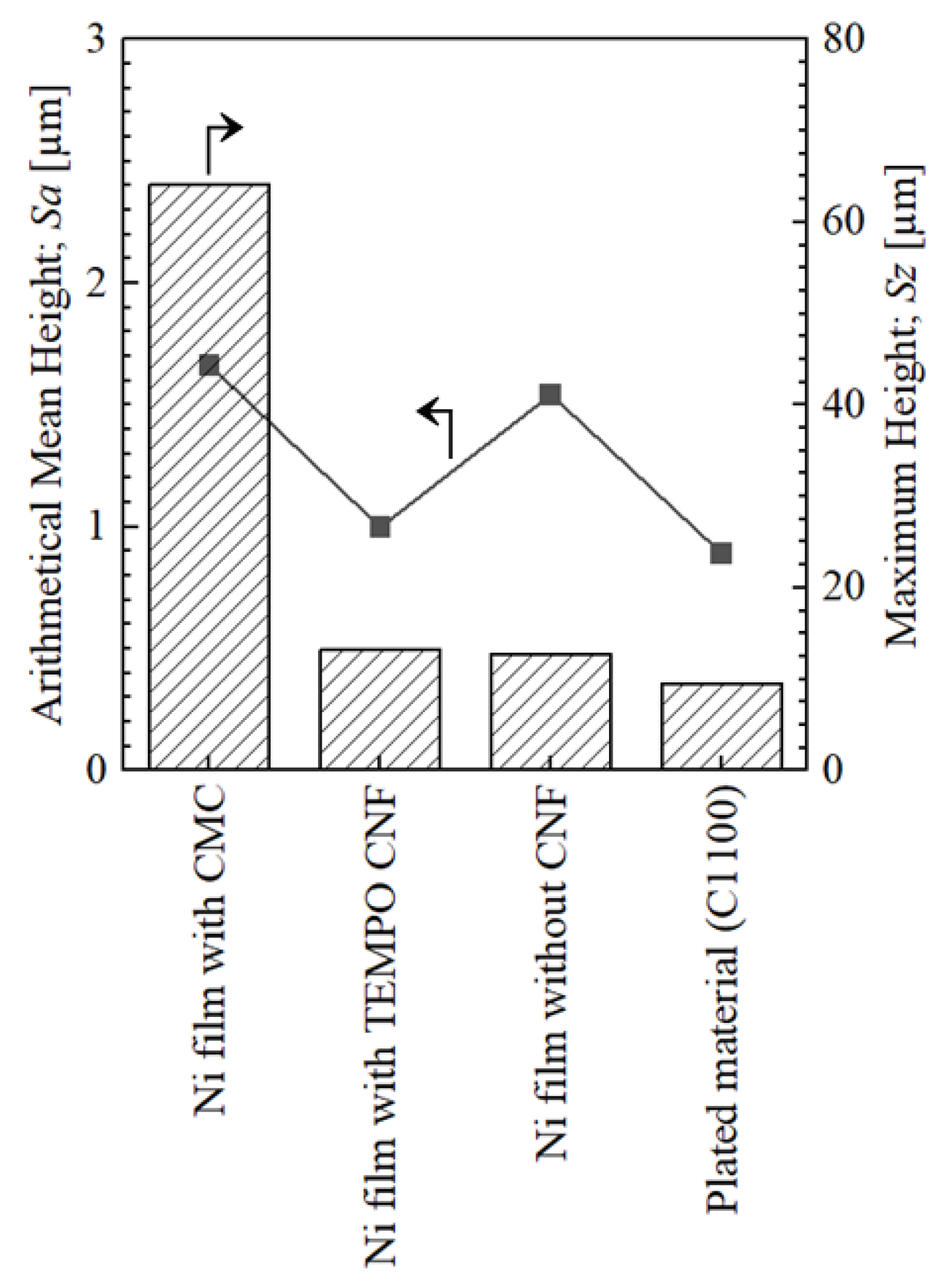
2.3.2. Surface Roughness Measurement

The surface roughness of the obtained plated films was measured using a laser microscope (VK-X150, KEYENCE, Osaka, Japan). The measurement area was 1.0 × 1.4 mm near the center of the surface of the plated film. Note that surface roughness in this study: arithmetical mean height; Sa and maximum height; Sz, indicate the area roughness in accordance with ISO 25178.

2.3.3. Quantification Analysis

To quantify the amount of cellulose in the plated film, quantification analysis was performed on the surface of the plated film using the EPMA. The beam current was 10 nA, the analysis area was 1.0 × 1.4 mm, and the center of the surface of the plated film was targeted for analysis. Since the amount of cellulose (C6H10O5) as a compound is not quantifiable due to the characteristics of the device, the method of registering a dried and solidified slurry of CNF (nanoforest-S from Chuetsu Pulp & Paper, Takaoka, 10.83 mass% slurry) as a standard sample of 100 mass% carbon was adopted. In this method, the quantified value of carbon is readable as a pseudo-quantified value of cellulose, and the amount of cellulose equivalent in the plated film is measurable.

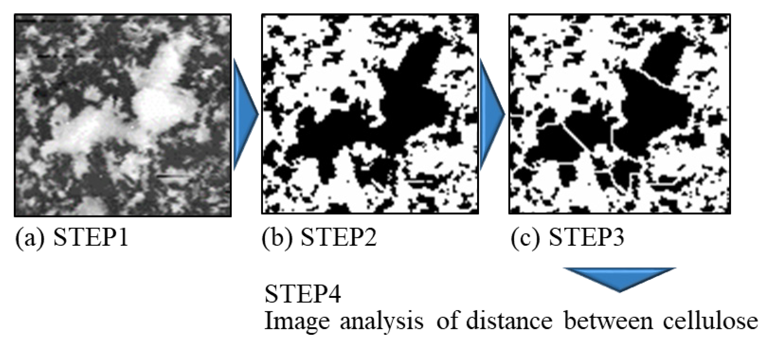
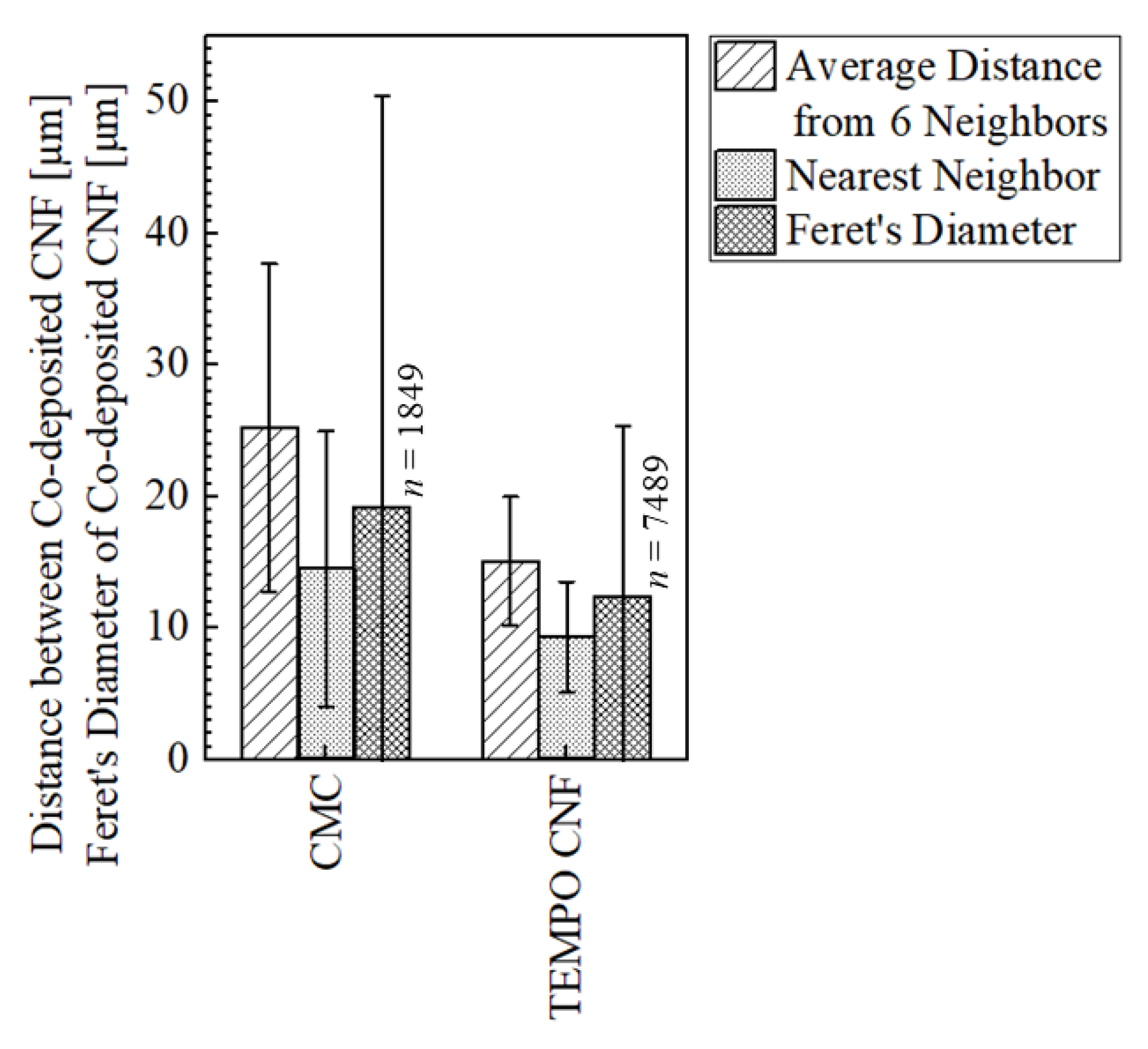
2.3.4. Evaluation of Dispersion of CNF in Plated Film

The degree of dispersion of co-deposited CNF in the plated film was evaluated using image analysis of the composition image of the surface of plated film.
The composition images of the surface of plated films were obtained as backscattered electron (BSE) or absorbed current (SC) images using the EPMA. The reasons for using the BSE and SC images are described below. The average of the averaged center-of-gravity distances between six neighbors and the center-of-gravity distances between the nearest neighbor CNF were calculated based on the composition images in the range of 1.1 × 1.5 mm, using the image analysis software ImageJ 1.53e [27] and its plug-in, ND [28]. Hereafter, unless otherwise noted, the distance between CNFs represents center-of-gravity distance. Feret’s diameter of co-deposited CNF was also measured. After the composition image was converted to a black-and-white binarized image, the cellulose area was divided by watershed algorithm, and then the distance between CNFs was analyzed. Figure 4 shows an overview of the analysis procedure. The reason for applying the watershed treatment is to prevent the overlapping CNF from being recognized as a very large mass when observed from the surface due to the two-dimensional image analysis. In the binarization process, areas where the CNF and Ni areas were clearly not properly distinguished were manually image modified.

2.3.5. Vickers Hardness Test

The Vickers hardness tester was used to measure the Vickers hardness near the center of the surface of the obtained plated film. The test conditions were set to a loading load of 25 gf and a loading time of 15 s. Based on the results of a previous study [10], the hardness of the Ni-plated film without cellulose was estimated to be approximately 300 HV, and the calculated film thickness at 3000 C/dm2 to be approximately 10 µm from Equation (1) at assumed cathodic current efficiency of 100%; thus, the indentation depth was estimated to be less than one-fifth of the film thickness at this load. Matsuda reported the study by Aoki et al., that when the hardness of the plated metal is 1.7–33.3 times the hardness of the substrate metal, the indentation depth, at which the hardness of the plated metal is not affected by the substrate, is less than 1/5–1/9.8 of the plated film thickness [29].
d = σ / F n × M ρ × η
  • d = thickness of plated metal μ m ,
  • σ = charge density C / d m 2 ,
  • F = Faraday constant C / mol ,
  • n = ion valence of plated metal ,
  • M = molar mass of plated metal g / mol ,
  • ρ = density of plated metal g / cm 3 ,
  • η = cathodic current efficiency [ % ]

3. Results and Discussions

3.1. Morphology and Microstructure of Plated Films
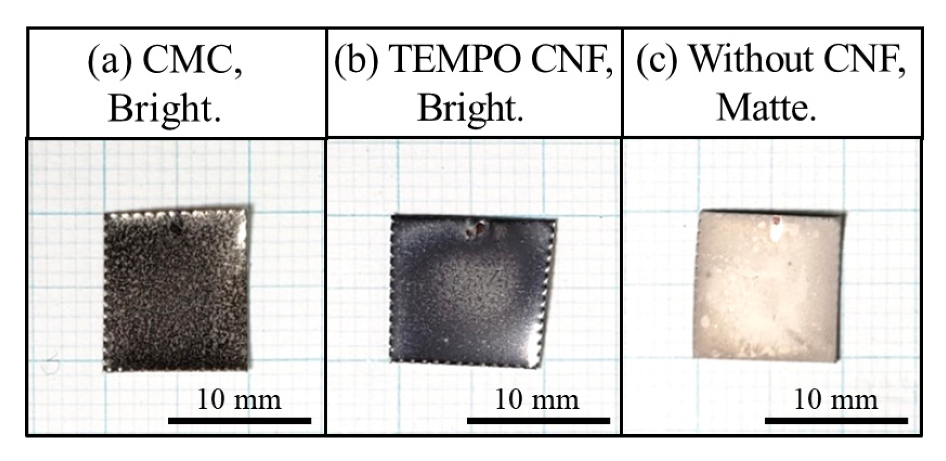
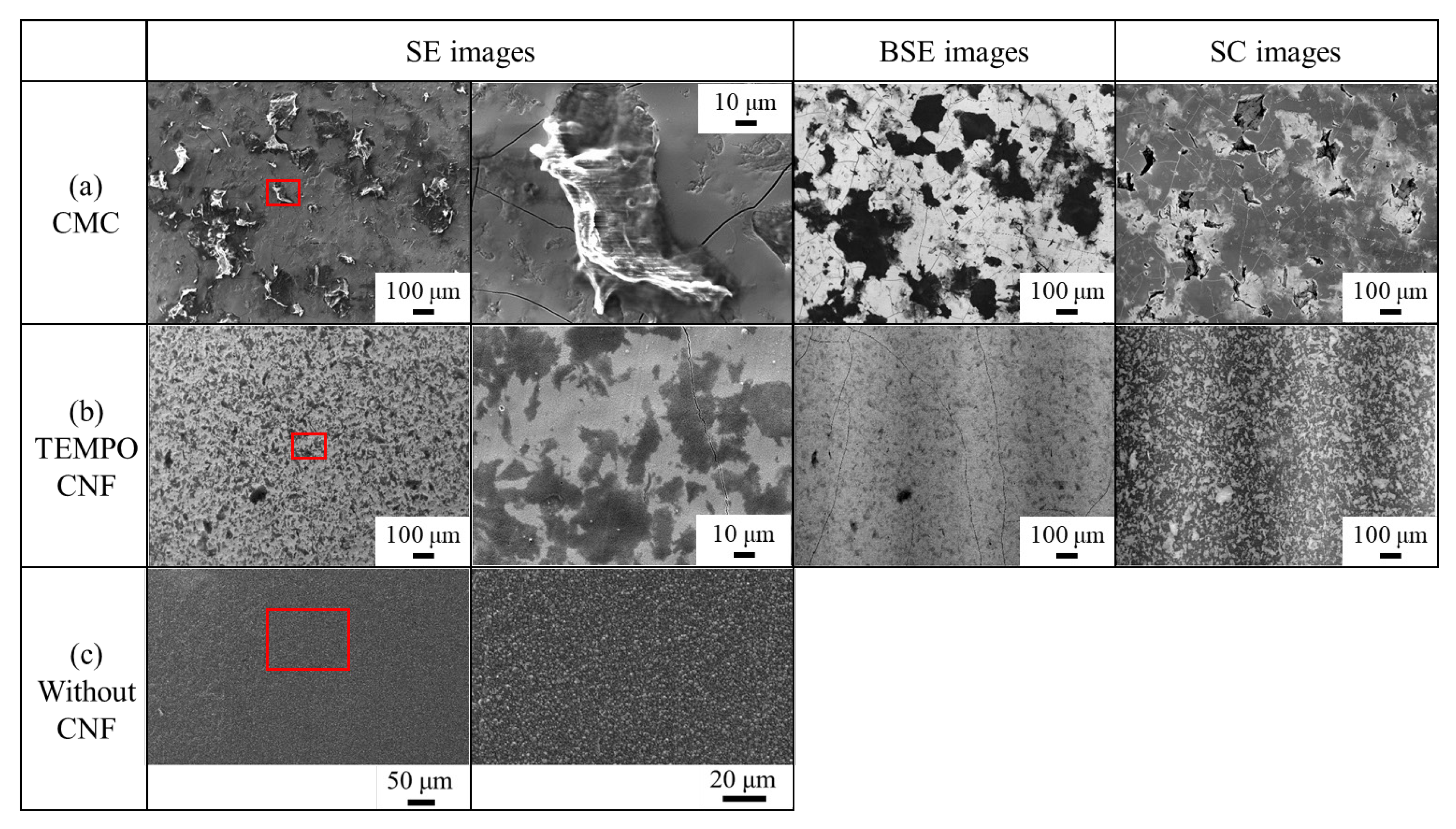
3.1.1. Morphology

Figure 5 shows the appearances of the plated films. The specimen without CNF had a matte appearance, whereas both of the specimens with CMC and TEMPO CNF had a bright appearance. It is generally known that Ni-plated films deposited from Watts baths without additives have a matted surface [30]. CMC and TEMPO CNF are characterized by the introduction of carboxy groups, which probably affected the appearance of the plated film. Doi et al., conducted an experiment using citric acid, which is a carboxylic acid with carboxy groups, as an additive, and reported that a brighter and smoother film was obtained compared to that fabricated with Watts bath [31]. Regarding that, Doi explained that nickel is electrodeposited from the chelate complex formed by nickel ions and citric acid ions in which hydrogen is ionized from the carboxy group of citric acid, resulting in a nickel film with random orientation properties and fine crystal grains [32]. This grain refinement effect seems to suppress the graining and produce a bright appearance such as the specimens with CMC or TEMPO CNF.
Figure 6 shows the surface roughness of the obtained plated films and the plated material, C1100. The maximum height Sz is the same as the maximum height of the parts where CNF co-deposited in the measurement range. Since the co-deposited CMC has a large diameter, Sz of the co-deposited part was 64.1 μm, which is the highest value in this study. On the other hand, Sz of the co-deposited parts of TEMPO CNF was 13.2 μm, which was almost the same as that of the Ni-plated film without CNF. In terms of arithmetic mean height Sa, TEMPO CNF showed a value of 1.0 μm, which is less than the value of 1.5 μm of the Ni-plated film without CNF. This is almost the same value as that of the plated material which is 0.9 μm. The reason for this is probably due to the suppression effect of the graining described above. There was no correlation between the surface roughness and brightness. Even the specimen with CMC that had the highest Sz showed a good brightness in the appearance (Figure 5a). The grainy states of the surfaces of the plated films are shown in the next subsection. It seems that the graining of deposited nickel is important as an indicator for brightness for the naked eye, rather than Sz or Sa, in a certain range including the CNF co-deposited parts.

3.1.2. Microstructure of Surface

SE images of the surface of the plated films are shown in Figure 7. Co-deposition was observed in the both specimens with CMC and TEMPO CNF. CMC was characterized by the co-deposition of short cellulose fibers with low aspect or in the form of particles, which seem to pierce the Ni part. Black speckled areas were observed in the specimen with TEMPO CNF. These are considered to be TEMPO CNF aggregates. However, unlike the co-deposited areas of CMC, those of TEMPO CNF are characterized by the fact that they show almost no unevenness. The BSE and SC images are also shown in Figure 7, where the black and white area indicate the CNF, respectively. Particle-like CMC with small aspect ratio was observed in both of the BSE and SC images. In the specimen with TEMPO CNF, the black areas, which indicate CNF areas in the SE image, coincide with the white areas, which are CNF areas in the SC image. On the other hand, in the BSE image, the obtained contrast was relatively low, although faint TEMPO CNF areas were able to be identified. Figure 8 shows the magnified SE images of the grainy state on the surfaces of the plated films. The specimen without CNF shows the grainy surface of the deposited nickel and did not show a brightness in appearance. The grain refinement effect due to Ni deposition via chelate complex of Ni ions and ionized carboxy groups (carboxylates) described above seems to suppress the graining and produce a bright appearance. It is also considered that the inclusion of CNF also inhibits nuclear growth during the Ni deposition and growing process and promotes nucleation, thereby exerting the refinement effect of the crystal grain size and suppressing the graining [10,33]. However, since the degree of graining of the surface of the plated film does not necessarily depend on the crystal grain size [34,35], it should be understood that the refinement effect of the crystal grain size acted as an effect of reducing the graining in this study case.
Figure 9 shows the quantified values of cellulose equivalent at the surface of the obtained plated films and the type of CNF suspended in the plating bath. Hereafter, error bars in the graphs indicate standard deviations. As a comparison, the quantitative results of Ni-plated film without CNF and Ni standard sample for quantitative analysis are also shown. The specimen with CMC had higher average amount of cellulose in the films, reaching 42.6 mass%. On the other hand, in that with TEMPO CNF, it was only 8.43 mass%. Since the values of approximately 5 mass% were also shown in the quantification of Ni-plated film without cellulose and Ni standard sample, it should be noted that at least approximately 5 mass% of the quantified value is background noise in the cellulose-quantification method used in this study.
Figure 10 shows the distance between co-deposited CNF and Feret’s diameter of co-deposited CNF on the surface of the obtained plated film. The compositional images; BSE and SC images shown in Figure 7 were used for image analysis of this result of the specimens with CMC and TEMPO CNF, respectively. Although the same conditions are desirable for the images used for image analysis, the BSE and SC images were used separately, since the stronger contrast between the co-deposited area and the Ni area is clearer in the binarized image. The distance between co-deposited CNF was larger between CMC than TEMPO CNF, the average of the average distance between 6 neighbors was 25.2 μm and its Feret’s diameter was 19.2 μm with large error bar. This indicates that the co-deposition was sparse. On the other hand, the average of the distance between TEMPO CNF was 18.7 μm and its Feret’s diameter was 12.5 μm, which indicates that it was quantitatively confirmed that fine co-deposition was obtained. Since the co-deposition mechanism of both CMC and TEMPO CNF described in the below section is considered to be the same, the difference in the degree of dispersion is simply attributable to the difference in the CNF size distribution inside the plating solution state (Figure 2). Although affected by the agglomeration phenomenon in the plating solution, the peaks in the plating solution with CMC are approximately 50 µm, whereas the peaks in that with TEMPO CNF are approximately 0.1 µm and 3 µm. This indicates that TEMPO CNF was more finely dispersed in the plating solution.

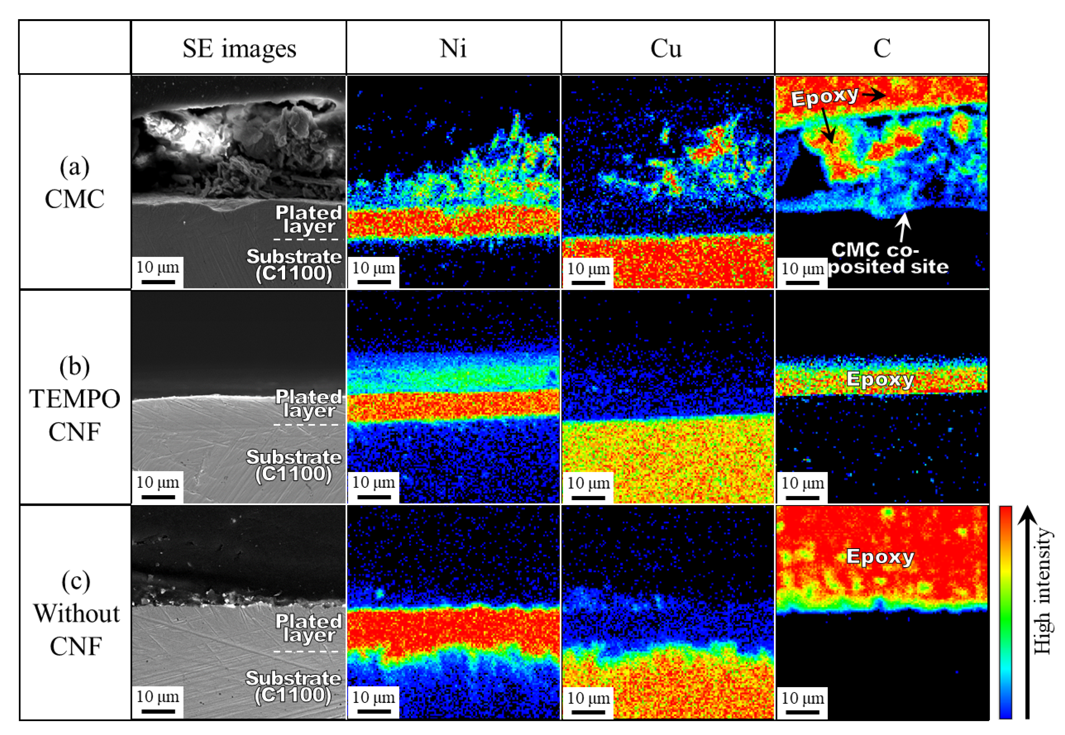
3.1.3. Microstructure of Cross-Section

Figure 11 shows the SE and elemental mapping images of the cross-sections of the plated films. Note that although the mapping analysis of carbon (C) is derived from CNF, carbon derived from epoxy resin is also detected since the specimens are embedded in epoxy resin for cross-sectional observation. The thickness of the electrodeposited Ni layer of all of the specimens was approximately 10 μm, which is equivalent to the calculated value, indicating that the Ni film was plated with high current efficiency. In the specimen with CMC, co-deposition of large diameter CMC was observed in the cross section with Ni deposition in the co-deposited site. It is considered that CNF is fixed to the surface of the plated film by the deposition of Ni atoms coordinated to the CNF surface, and Ni deposition from them coordinated to the cleavage region inside the large diameter CMC is considered to cause this Ni-mapping result. Copper detected in the co-deposited area is supposed to be surface diffusion from the plated material via such pits. Although the specimen with TEMPO CNF did not show large scale co-deposited sites as did that with CMC, it is assumed that fine CNF is incorporated into the electrodeposited Ni film according to the surface observation results with smooth co-deposited sites. However, even if CNF with the nano-scale were incorporated into the Ni film, it would be difficult to confirm them by image observation due to the limitations of the performance of the EPMA equipment. In order to clarify the distinction between CNF-derived carbon and epoxy resin-derived carbon, a method of cross-sectional observation that does not embed the specimen in epoxy resin is being considered.

3.2. Vickers Hardness of Plated Films

Figure 12 shows the Vickers hardness of the surface of the obtained plated films and the plated material, C1100. The specimen with CMC was the hardest in this study, reaching 434 HV. This value is approximately 82% higher than the 239 HV of the Ni-plated film without CNF. The specimen with TEMPO CNF was 409 HV, slightly less than that of CMC, though approximately 71% harder than that of the Ni-plated film without CNF.
The factor of the effect of hardness enhancement of the plated film obtained from the plating bath with CNF is considered to be dividable into (1) refinement of crystal grain size and (2) dispersion strengthening by the composition of CNF. The former is assumed to be further dividable into refinement by Ni deposition from the chelate complex [32] and refinement due to nucleation promoted by the incorporation of CNF. These factors are described in detail in the next section. Measurement of crystal grain size using the electron backscattered diffraction (EBSD) method or estimation of crystallite size using the X-ray diffraction (XRD) method is expected to be performed in a future study.

3.3. Co-Deposition Mechanism

Figure 13 shows the schematic model of the co-deposition mechanism when CNFs with carboxy groups are introduced. In this study, CMC and TEMPO CNF are used as co-deposited materials.
STEP 1 shows the state before plating starts. Here, carboxy-groups-introduced CNF (R-COOX, where X is hydrogen or metal such as sodium) is in the state of an anion [R-(COO)n] or forming a chelate complex between a Ni ion and two carboxylates [32] [R-(COO)2mNim, -(COO)k]. Since the CNF is a polymer, many carboxy groups have been introduced. The apparent charge of the entire complex is negative due to the presence of carboxylates that are not coordinated with Ni ions. Then, the Ni ions in the plating solution coordinate one-to-one with the remaining free carboxylate sites, and the apparent charge of the entire complex becomes positive [32] [R-(COO)2mNim, -(COO)kNik]+.
STEP 2 represents the initial state of plating. The anion [R-(COO)n] and the negative charged complex [R-(COO)2mNim, -(COO)k], and the positive charged complex [R-(COO)2mNim, -(COO)kNik]+ would be affected by the electrostatic force with the plated material when the current is applied as repulsion and attraction, respectively. The latter is transported to the surface of the plated material under the effects of electrostatic force and agitation flow and electrons are supplied to the complex that contacts the surface of the plated material. Coordinated nickel is continuously deposited from the bi- or uni-dentate coordination sites randomly, and then the grains of deposited nickel become finer with random orientation [32]. At the same time, the complex that has lost nickel is unable to maintain its anionic state in the low pH region near the surface of the plating material, and is considered to be incorporated into the deposited metal nickel in its original stable state of R-(COOH)n by bonding with H ions. In this step, the anionic state prevents CNF from aggregating with each other, which is supposed to enable the fine dispersion and co-deposition of CNF in the Ni film. Therefore, it is possible to consider that the hardness enhancement effect is caused in this step by the Ni grain refinement and dispersion strengthening described in the previous section due to Ni deposition from the complex and fine co-deposition of the cellulose material.
STEP 3 represents the continuous growth of the composite plating film through repetition of STEP 2. Ni ions are transported to the surface of the plated material at this step by electrostatic forces, agitation currents, and diffusion due to concentration gradients.
Since the deposition of coordinated metal atoms is important for the fixation of CNF in the state of complexes that contact the surface of the plated material, a higher amount of the coordinated metal atoms per weight would be advantageous for co-deposition. For example, the amount of carboxy groups in natural cellulose refined from cotton [10] is 12.81–43.26 mmol/kg [36]. Although it varies depending on the degree of substitution into carboxymethyl groups, that of CMC is 1223–2234 mmol/kg [37]. That of TEMPO CNF is said to reach 1700 mmol/kg [38]. In other words, CMC and TEMPO CNF have approximately more than 10 times more carboxylate sites per weight, and are able to coordinate metal atoms in the plating solution compared to natural cellulose. If the aforementioned mechanism is dominant in co-deposition, it seems desirable to apply carboxy-group-introduced CNFs such as CMC and TEMPO CNF as the co-deposited materials in the composite-electroplating method. Compared to CMC and TEMPO CNF, the literature values of the amount of carboxy groups introduced per weight, as mentioned above, indicate that the amount of coordinated Ni atoms with carboxylates does not seem to differ by a factor of two, and the difference is expected to be within a factor of 1.4 at most. Therefore, it is considered that the probability of fixation of CMC or TEMPO CNF that contacts the surface of the plated material in the complex state is approximately the same for both CNF. However, the quantitative analysis result showed that the amount of co-deposited cellulose in the specimen with CMC was almost five times higher than that with TEMPO CNF (Figure 9). The reason for this is possibly considered to be caused by the method of quantification of the plated films. Assumed that both CMC and TEMPO CNF are well dispersed in the plating solution, although CMC seems to be slower in terms of weight of CNF per unit, both are moving at approximately the same speed in the plating solution due to the agitation flow. Since the suspended amount is the same at 1 g/L, it is possible to estimate that the weight of CNF in contact with the surface of the plated material per unit time is comparable. Further, as mentioned above, the probability of fixation of contacted CMC or TEMPO CNF is estimated to be similar, thus there should not be a factor-of-five difference in the net cellulose content in the entire plated film, at least. However, as seen from the SE and BSE images (Figure 7) and surface roughness (Figure 6), relatively large diameter CMC co-deposited sites are present on the surface of the specimen in a protruding form. This suggests that the specimens with CMC had a higher cellulose content in the method, in which the quantitative analysis was conducted on a certain range at the surface. As a quantification method for cellulose, chemical methods such as Prosky’s method or the high performance liquid chromatography method are well known [39]. However, in these methods, sample preparation is often time-consuming because of the preprocessing needed to convert the analysis subject into powder, liquid, and so on. Therefore, especially for metal-based specimens such as CNF-composited plated film, these methods are not appropriate [40]. Image analysis [40,41] and X-ray fluorescence (XRF) methods [10,40] have been attempted in the previous studies. In the EPMA method in this study, information from the surface was still dominant in the analysis results, as was the case with these previous methods. However, compared to the image analysis method, for which the accuracy is difficult to evaluate, and the XRF method, for which it is difficult to detect light elements due to its principle, and has an error of 1% order in the case of cellulose, it is possible to say that the EPMA method has practical reproducibility, though background effects must be taken into account.

4. Conclusions

In this study, carboxy groups introduced cellulose nanofibers, CNF: sodium carboxymethyl cellulose, CMC and TEMPO oxidized cellulose nanofibers, TEMPO CNF were subjected to the addition to the Ni-plating bath, and the properties of the obtained Ni-CNF composite plating film were investigated in order to obtain homogeneous co-deposition of CNF into the Ni-electroplating film and to elucidate the co-deposition mechanism. As a result, the following conclusions were obtained.
  • Co-deposition was observed with both CMC and TEMPO CNF.
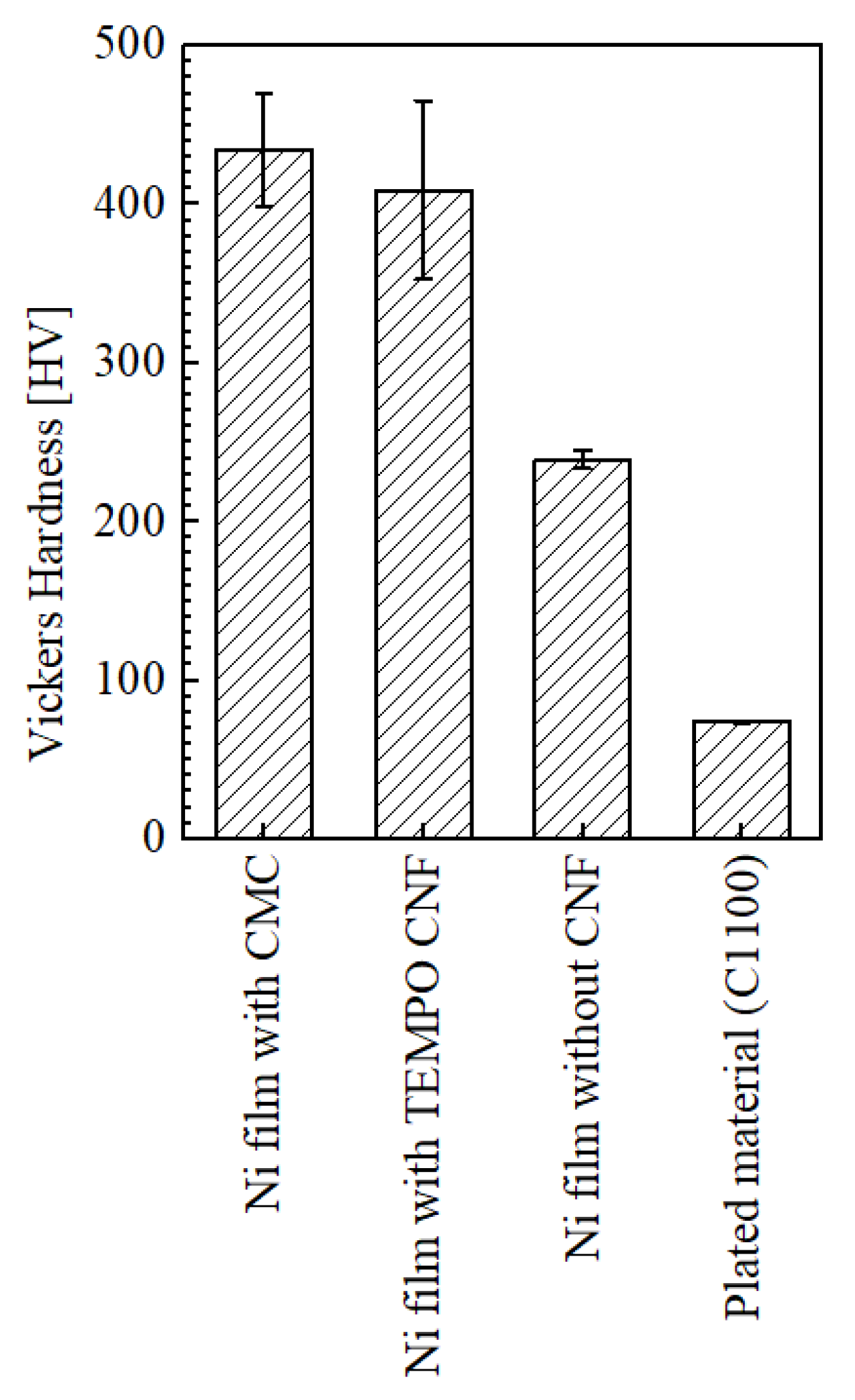
  • The surface Vickers hardness of the specimen with CMC was higher than that of TEMPO CNF, and the hardness improvement was approximately 82% compared to the conventional Ni-plated film without CNF. Even though the hardness of the specimen with TEMPO CNF was slightly inferior, it was improved by approximately 71%.
  • The image analysis showed that the average distance between the co-deposited TEMPO CNF was shorter than that of CMC by approximately 40%, indicating a fine and dense co-deposited morphology.
  • The surface roughness of the specimen with TEMPO CNF was significantly smooth and that was superior compared to the conventional Ni-plated film, whereas that with CMC had a noticeably rougher surface.
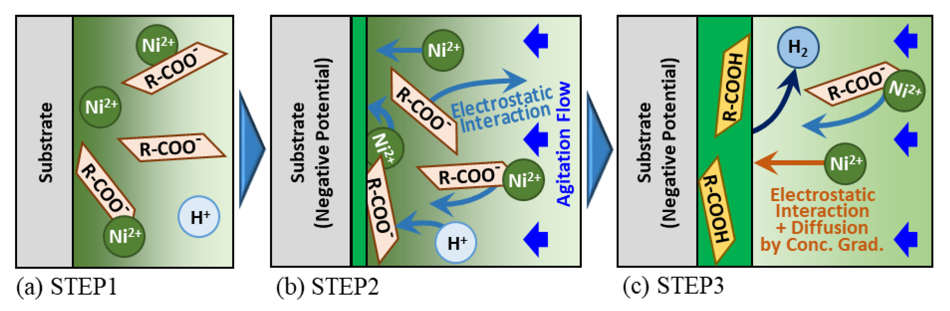
  • Models for the co-deposition mechanism of Ni-CNF composite electroplating were proposed in the case of CNF with introduced carboxy groups on the surface. In this model, nickel is deposited from the chelate complex formed between the carboxylate of CNF and Ni ion. It was considered that this causes CNF to be incorporated into the Ni-plated film and improves hardness through grain refinement and dispersion strengthening effects simultaneously.
The results and discussions obtained in this study will be greatly useful in the fabrication of high wear resistance film by composite plating method using CNF, which is a sustainable resource. In particular, future research reports are expected to include studies on the optimal conditions of plating film fabrication, such as wear tests using TEMPO CNF, which showed superior hardness enhancement and dispersion properties in the plated films, with potential application to actual products in consideration.

Author Contributions

Conceptualization, M.I.; Methodology, M.I. and W.K.; Formal analysis, M.I.; Investigation, M.I. and W.K.; Resources, T.K. and I.S.; Writing—original draft, M.I.; Writing—review & editing, W.K., T.K., I.S. and K.S.; Visualization, M.I., W.K. and K.S.; Supervision, T.K., I.S. and K.S.; Project administration, I.S.; Funding acquisition, I.S. All authors have read and agreed to the published version of the manuscript.

Funding

This research was funded by JSPS KAKENHI grant number JP22K04721.

Acknowledgments

The authors gratefully appreciate Nippon paper Industries, Ltd. for the free donation of CNF samples, and Satoshi Kuwahara of Tokyo metropolitan industrial technology research institute for his invaluable advice in considering the co-deposition mechanism. Further, this study was supported by Grant-in-Aid for Scientific Research “JSPS KAKENHI Grant Number JP22K04721”. We express our gratitude for the support.

Conflicts of Interest

The authors declare no conflict of interest.

References

  1. Janowiak, M.; Webster, C. Promoting ecological sustainability in woody biomass harvesting. J. For. 2010, 108, 16–23. [Google Scholar]
  2. Spîrchez, C.; Lunguleasa, A.; Croitoru, C. The importance of the wood biomass in environment protection. AIP Conf. Proc. 2017, 1918, 02007. [Google Scholar]
  3. Gosalvez, E. Biomass: A Sustainable Energy Source for the Future? College of Natural Resources News, North Carolina State University: Raleigh, NC, USA, 15 January 2021. Available online: https://cnr.ncsu.edu/news/2021/01/biomass-a-sustainable-energy-source-for-the-future/ (accessed on 11 May 2023).
  4. Yano, H. Cellulose nanofibers and their utilization. J. Imaging Soc. Jpn. 2016, 55, 356–360. [Google Scholar]
  5. Nogi, M.; Iwamoto, S.; Nakagaito, A.N.; Yano, H. Optically transparent nanofiber paper. Adv. Mater. 2009, 21, 1595–1598. [Google Scholar] [CrossRef]
  6. Moon, D.; Tsukahara, K.; Sagisaka, M.; Tahara, K. Effect of cellulose nanofibers composites in automotive components on greenhouse gas emissions. J. Jpn. Inst. Energy 2016, 95, 648–652. [Google Scholar] [CrossRef]
  7. Nogi, M.; Yano, H. Transparent nanocomposites based on cellulose produced by bacteria offer potential innovation in the electronics device industry. Adv. Mater. 2008, 20, 1849–1852. [Google Scholar] [CrossRef]
  8. Norrrahim, M.N.F.; Kasim, N.A.M.; Knight, V.F.; Halim, N.A.; Shah, N.A.A.; Noor, S.A.M.; Jamal, S.H.; Ong, K.K.; Wan Yunus, W.M.Z.; Farid, M.A.A.; et al. Performance evaluation of cellulose nanofiber reinforced polymer composites. Funct. Compos. Struct. 2021, 3, 024001. [Google Scholar] [CrossRef]
  9. Phuong, H.T.; Thoa, N.K.; Tuyet, P.T.A.; Van, Q.N.; Hai, Y.D. Cellulose nanomaterials as a future, sustainable and renewable material. Crystals 2022, 12, 106. [Google Scholar] [CrossRef]
  10. Iioka, M.; Kawanabe, W.; Shohji, I.; Kobayashi, T. An experimental study of fabrication of cellulose nano-fiber composited Ni film by electroplating. Mater. Trans. 2022, 63, 821–828. [Google Scholar] [CrossRef]
  11. Shohji, I.; Watanabe, H.; Okashita, T.; Osawa, T. Impact properties of lead-free Sn-Ag-Cu-Ni-Ge solder joint with Cu electrode. Mater. Trans. 2008, 49, 1513–1517. [Google Scholar] [CrossRef]
  12. Sun, L.; Zhang, L. Properties and microstructures of Sn-Ag-Cu-X lead-free solder joints in electronic packaging. Adv. Mater. Sci. Eng. 2015, 2015, 639028. [Google Scholar] [CrossRef]
  13. Holmberg, K.; Erdemir, A. Influence of tribology on global energy consumption, costs and emissions. Friction 2017, 5, 263–284. [Google Scholar] [CrossRef]
  14. Gu, Y.; Xia, K.; Wu, D.; Mou, J.; Zheng, S. Technical characteristics and wear-resistant mechanism of nano coatings: A review. Coatings 2020, 10, 233. [Google Scholar] [CrossRef]
  15. Zaki, E.G.; Selim, M.S.; Hao, Z.; Elsaeed, S.M.; El-Saeed, A.M. Special issue: Recent trends in wear and erosion resistance of alloys. Coatings 2023, 13, 64. [Google Scholar] [CrossRef]
  16. Rahman, M.S.; Hasan, M.S.; Nitai, A.S.; Nam, S.; Karmakar, A.K.; Ahsan, M.S.; Shiddiky, M.J.A.; Ahmed, M.B. Recent development of carboxymethyl cellulose. Polymers 2021, 13, 1345. [Google Scholar] [CrossRef]
  17. Zennifer, A.; Senthilvelan, P.; Sethuraman, S.; Sundaramurthi, D. Key advances of carboxymethyl cellulose in tissue engineering & 3D bioprinting applications. Carbohydr. Polym. 2021, 256, 117561. [Google Scholar]
  18. Saito, T.; Isogai, A. TEMPO-mediated oxidation of native cellulose. The effect of oxidation conditions on chemical and crystal structures of the water-insoluble fractions. Biomacromolecules 2004, 5, 1983–1989. [Google Scholar] [CrossRef]
  19. Saito, T.; Isogai, A. Ion-exchange behavior of carboxylate groups in fibrous cellulose oxidized by the TEMPO-mediated system. Carbohydr. Polym. 2005, 61, 183–190. [Google Scholar] [CrossRef]
  20. Saito, T.; Okita, Y.; Nge, T.T.; Sugiyama, J.; Isogai, A. TEMPO-mediated oxidation of native cellulose. Microscopic analysis of fibrous fractions in the oxidized products. Carbohydr. Polym. 2006, 65, 435–440. [Google Scholar] [CrossRef]
  21. Kwon, G.; Lee, K.; Kim, D.; Jeon, Y.; Kim, U.-J.; You, J. Cellulose nanocrystal-coated TEMPO-oxidized cellulose nanofiber films for high performance all-cellulose nanocomposites. J. Hazard. Mater. 2020, 398, 123100. [Google Scholar] [CrossRef]
  22. Kaffashsaie, E.; Yousefi, H.; Nishino, T.; Matsumoto, T.; Mashkour, M.; Madhoushi, M.; Kawaguchi, H. Direct conversion of raw wood to TEMPO-oxidized cellulose nanofibers. Carbohydr. Polym. 2021, 262, 117938. [Google Scholar] [CrossRef]
  23. Isogai, A. Emerging nanocellulose technologies: Recent developments. Adv. Mater. 2020, 33, 2000630. [Google Scholar] [CrossRef] [PubMed]
  24. Isogai, A. Cellulose nanofibers. J. Surf. Finish. Soc. Jpn. 2020, 71, 389–395. [Google Scholar] [CrossRef]
  25. By courtesy of Nippon Paper Industries, Chiyoda-ku, Japan, 16 May 2023.
  26. Bari, G.A.D. Electrodeposition of nickel. In Modern Electroplating, 5th ed.; Schlesinger, M., Paunovic, M., Eds.; John Wiley & Sons: Hoboken, NJ, USA, 2011; pp. 79–114. [Google Scholar]
  27. Rasband, W.S. ImageJ: U.S. National Institutes of Health, Bethesda, MD, USA, 1997–2020. Available online: https://imagej.nih.gov/ij/ (accessed on 3 April 2023).
  28. Haeri, M.; Haeri, M. ImageJ plugin for analysis of porous scaffolds used in tissue engineering. J. Open Res. Softw. 2015, 3, e1. [Google Scholar] [CrossRef]
  29. Matsuda, K. The hardness of electro plated coatings. J. Jpn. Soc. Tribol. 1995, 40, 234–239. [Google Scholar]
  30. Rose, I.; Whittington, C. Chemistry of nickel electroplating solutions. In Nickel Plating Handbook 2014, 1st ed.; Nickel Institute: Brussels, Belgium, 2014; pp. 13–16. [Google Scholar]
  31. Doi, T.; Mizumoto, K.; Aonuma, M.; Tanaka, S. Properties of the film from nickel electroplating bath using citric acid. J. Surf. Finish. Soc. Jpn. 2002, 53, 335–340. [Google Scholar] [CrossRef]
  32. Doi, T. Acting mechanism of citric acid on the properties of nickel citrate electroplated film. Bull. Tokyo Metrop. Ind. Technol. Res. Inst. 2015, 10, 18–21. [Google Scholar]
  33. Nakahara, S. Incorporation of impurities in deposited film. J. Surf. Finish. Soc. Jpn. 2012, 63, 200–208. [Google Scholar] [CrossRef]
  34. Watanabe, T. Structure control theory of plated film—Part of surface morphology. J. Jpn. Inst. Metals 2002, 66, 339–349. [Google Scholar] [CrossRef]
  35. Watanabe, T. Structure control theory of plated film—Part of crystal size. J. Jpn. Inst. Metals 2002, 66, 350–361. [Google Scholar] [CrossRef]
  36. Fras, L.; Stana-Kleinschek, K.; Ribitsch, V.; Sfiligoj-Smole, M.; Kreze, T. Quantitative determination of carboxyl groups in cellulose by complexometric titration. Lenzing. Ber. 2002, 81, 80–88. [Google Scholar]
  37. Yamamoto, M.; Noguchi, H.; Kubota, H.; Ogiwara, Y. Generation of wet strength in paper sheet made of fibrous carboxymethyl cellulose. Jpn. TAPPI J. 1975, 29, 247–253. [Google Scholar] [CrossRef]
  38. Isogai, A.; Saito, T.; Fukuzumi, H. TEMPO-oxidized cellulose nanofibers. Nanoscale 2011, 3, 71–85. [Google Scholar] [CrossRef] [PubMed]
  39. Mori, B. Dietary fiber: Determination methods and definition. J. Jpn. Assoc. Diet. Fiber Res. 1999, 3, 1–11. [Google Scholar]
  40. Iioka, M.; Shohji, I.; Kobayashi, T. Accuracy assessment of quantification method of cellulose nano-fiber in nickel plating film using image analysis. In Proceedings of the 2021 International Conference on Electronics Packaging, Online, 13 May 2021; pp. 177–178. [Google Scholar]
  41. Iioka, M.; Shohji, I.; Kobayashi, T. Fundamental research of forming conditions of cellulose nano-fiber composited nickel plating film. In Proceedings of the 27th Symposium on Microjoining and Assembly Technology in Electronics, Online, 2–15 February 2021; pp. 290–291. [Google Scholar]
Figure 1. Representative AFM images of TEMPO CNF (a) and CMC (c), and structural formulas of them, (b,d), respectively [25].
Surfaces 06 00012 g001
Figure 2. The number frequency distribution of size of suspended CNF in plating solution after pre-stirring measured by DLS with Contin method at 25 °C at range of 10–1,000,000 nm.
Surfaces 06 00012 g002
Figure 3. Relation between placement position of plated material and direction of agitation flow as viewed from top of beaker.
Surfaces 06 00012 g003
Figure 4. Overview of image analysis procedure of distance between CNFs in plated film. Black and white area after binalization indicates cellulose and nickel part, respectively. STEP 1 shows prepared composition image (SC or BSE image) (a); in STEP 2, binarization is performed (b), and in STEP 3, watershed treatment is applied (c).
Surfaces 06 00012 g004
Figure 5. Appearances of plated films obtained from plating solution suspended with CMC (a), TEMPO CNF (b) and without any CNF (c).
Surfaces 06 00012 g005
Figure 6. Results of surface roughness measurement for plated films and as received C1100.
Surfaces 06 00012 g006
Figure 7. SE, BSE, and SC images of surfaces of plated films obtained from plating solution suspended with CMC (a), TEMPO CNF (b), and without CNF (c). Right columns of SE images are magnified images of red frame area in left columns. BSE and SC images of films with CMC (a) and TEMPO CNF (b) are used for image analysis, respectively.
Surfaces 06 00012 g007
Figure 8. SE images of grainy state of surfaces of plated films obtained from plating solution suspended with CMC (a), TEMPO CNF (b), and without CNF (c).
Surfaces 06 00012 g008
Figure 9. Results of analysis for equivalent content of cellulose in plated films with and without CNF (n = 3).
Surfaces 06 00012 g009
Figure 10. Distance between co-deposited CNF and the Feret′s diameter of co-deposited CNF measured by image analysis for both types of co-deposited CMC and TEMPO CNF in the obtained films. The number n indicates the number of sites recognized as CNF.
Surfaces 06 00012 g010
Figure 11. SE and elemental mapping images of cross-section of plated films obtained from plating solution suspended with CMC (a), TEMPO CNF (b) and without CNF (c).
Surfaces 06 00012 g011
Figure 12. Results of Vickers hardness measurement of plated films with and without CNF (n = 3).
Surfaces 06 00012 g012
Figure 13. Schematic model of co-deposition mechanism of carboxy groups introduced CNF into Ni-plated film. “R” represents backbone structural part of cellulose. STEP 1 shows state before plating (a), STEP 2 shows initial state of plating process (b), and STEP 3 shows growth of composite plating film (c).
Surfaces 06 00012 g013
Table 1. Composition of plating solution.
Distilled WaterNiSO4·6H2ONiCl2H3BO3CNF
[g/L]Bal.24030301 or 0
Disclaimer/Publisher’s Note: The statements, opinions and data contained in all publications are solely those of the individual author(s) and contributor(s) and not of MDPI and/or the editor(s). MDPI and/or the editor(s) disclaim responsibility for any injury to people or property resulting from any ideas, methods, instructions or products referred to in the content.

