Abstract
This research investigates deformation behavior of polystyrene (PS) as a thermoplastic resist material for the thermal nanoimprint lithography (T-NIL) process. Molecular dynamics modeling was conducted on a PS substrate with dimensions 58 × 65 × 61 Å that was imprinted with a rigid, spherical indenter. The effect of indenter size, force, and imprinting duration were evaluated in terms of indentation depth, penetration depth, recovery depth, and recovery percentage of the polymer. The results show that the largest indenter, regardless of force, has the most significant impact on deformation behavior. The 40 Å indenter with a 1 µN of force caused the surface molecules to descend to the lowest point compared to the other indenters. An increase in indenter size resulted in higher penetration depth, recovery depth, and recovery percentage. Higher durations of imprint cycle (400 fs) resulted in plastic deformation of the PS material with minimal recovery (4 Å). The results of this research lay the foundation for explaining the effect of several T-NIL process parameters on virgin PS thermoplastic resist material.
1. Introduction
Nanoimprint lithography (NIL) is a versatile high precision method to produce nanoscale features by mechanical deformation of an ultra-thin film polymer resist [1]. NIL was developed as a high throughput fabrication technique by Stephen Chou and his research team [2,3]. NIL has been applied to several applications including biological [4], photonic, and semiconductor electronics [5].
Nanoimprint lithography is broadly classified as thermal nanoimprint lithography (T-NIL) and ultra-violet lithography (UV-NIL). In the UV-NIL process, ultra-violet light is used to cure the polymer resist material on a substrate to fabricate nanoscale features using a transparent patterning mold. In this research, our group employs the T-NIL method, wherein a thermoplastic resist is applied onto a rigid substrate and imprinted by a rigid mold [6]. Typically, thermoplastic polymers transform to a glassy phase and aid deformation when heated up to their glass transition temperature (Tg). Different types of mold materials and geometries are implemented depending on the features to be imprinted [7]. Molds are fabricated using focused ion beam (FIB) technology from silicon and silicon dioxide materials. The NIL cycle begins with heating the ultra-thin film thermoplastic polymer to its glass transition temperature (Tg) on a substrate and inserting the mold to replicate its pattern. After complete insertion of the mold, it is held within the polymer for a desired duration followed by cooling to ambient temperature. Further, the mold is retracted from the polymer to retain its negative replica within the ultra-thin film resist material.
Nanoimprinting has been studied by various researchers from both experimental [4,8,9] and computational modeling [6,10,11] standpoints. The three critical process parameters in NIL, which include temperature, pressure, and imprint time, determine deformation behavior of the resist materials [12]. However, additional dependent variables such as layer thickness of resist material, geometry of indenter, aspect ratio of indenter, and application of an anti-stick layer also determine the NIL results [13,14,15]. Though experimental findings shed light on macroscopic behavior of polymers, the underlying physics and deformation mechanism needs further investigation. Atomistic models provide a seamless bridge to explaining this relationship [16,17,18,19]. Molecular dynamics (MD) simulations are vital in understanding surface interactions of materials at the atomistic scale. MD modeling can assist in understanding material deformation behavior in the NIL process, which cannot be captured by continuum-based models [20,21].
Molecular dynamics models of glassy atactic polystyrene under the influence of uniaxial mechanical deformation have been simulated for both initial elastic and postyield behavior [22]. MD modeling of bulk atactic polystyrene has been performed for chains up to 320 monomer units around Tg in a broad pressure range from 0.1 to 1000 MPa [23]. The authors further studied the correlated segmental dynamics in amorphous atactic polystyrene revealing Rouse behavior [24]. Eslami and Müller-Plathe have explored the solubility of different gasses in polystyrene over a wide range of temperatures and pressures [25]. Lie et al. have noted that the mechanical properties of polystyrene have been enhanced by embedding single-walled carbon nanotubes with repeat unit arrangements [26]. Ayyagari et al. have performed a molecular dynamics simulation study of atactic polystyrene (a-PS) and its dimer 2,4-diphenylpentane (DPP) using a previously derived quantum-chemistry-based explicit atom force field [27]. The X-ray structure factor of a-PS obtained from simulations was found to be in good agreement with the experiment. Yang et al. developed size and rate dependent finite deformation elastic–plastic constitutive relations for thin films of polystyrene [28]. Different modes of deformation were considered and homogenized to yield parametric representations of the constitutive model. A hybrid method was employed to study the mechanical behavior of silica–polystyrene nanocomposites (NCs) under uniaxial elongation [29]. Molecular dynamics and a finite element framework were used to study the interphase effects in silica–polystyrene composites.
Research conducted by in Zharick et al. [30] in 2018 showed that PS could be utilized to create nanostructures using electron beam lithography (EBL). Ma et al. [31] also demonstrated that a pattern of 20-nm period line array and 15-nm dot array could be achieved for an EBL resist. The authors also determined that PS is considerably more resistant to dry etching than PMMA. Thus, PS has been shown to be a low-cost alternative to PMMA for producing nanoscale features. There exist many molecular dynamics investigations of the chemical formulation of PS and studies pertaining to the mechanical behavior of PS, but no research currently utilizes PS as a thermoplastic resist for the molecular dynamics study of nanoimprint lithography. Our work investigates the interplay of different process parameters on the deformation behavior of PS in nanoimprint lithography using molecular dynamics modeling.
2. Materials and Methods
2.1. Polymer Formation
PS was used as the resist material for the NIL process. The chemical formula for PS, and its molecular structure of [24,32], is shown in Figure 1. Initial polymer chains were created in BIOVIA Materials Studio 6.0 [21,33]. One syndiotactic chain of PS was built and replicated to form the polymeric chain. The number of monomers per chain was 20. This polymer chain was replicated 4 times in the horizontal plane. Further, these were replicated into 5 vertical stacks to form a total polymer chain count of (4 × 5) = 20. Using a Materials Studio tool called Geometry Optimization, the placement of the molecules was arranged in a Newton consistent fashion. After initial formulation of the polymer chains, the entire system was relaxed similar to Kang et al. [34]. Relaxation was performed to bring the system to a state of thermal equilibrium. After the initial set-up, energy in the system was minimized over the course of 50,000 time steps using the smart minimizer function in Materials Studio. Graphical processing units (GPUs) from NVIDIA® Corporation (K40 and K20, with 2880 and 2496 cores, respectively) were employed to execute the simulations [35].
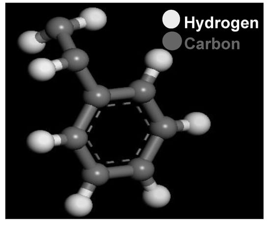
Figure 1.
Molecular formulation of PS chains.
Materials Studio implements a smart minimizer that combines steepest descent and conjugant gradient (cg) methods. The conjugant gradient is a general method to minimize a function f(x), where f can be any function of points in an N-dimensional space. The conjugant gradient searches the optimal design along the conjugate direction defined by:
where represents the scale factor, is search direction, is initial design, is functional value, and is gradient vector. The steepest descent is found using an algorithm that continues in the direction, which will minimize the value of a function, given the current point.
where is a point that takes steps of certain length, at direction from the previous point, .
In addition to minimization parameters, specifications about the force field must be identified. In this model, consistent valence force field (CVFF) force field was chosen. CVFF is applicable to many polymer systems based on [36,37,38,39]. CVFF provides for intermolecular interactions that occur within a polymeric MD simulation. The CVFF parameters for PS are shown in Table 1.

Table 1.
Consistent valence force field (CVFF) parameters for PS.
CVFF is parameterized by the following:
Bond stretching energy
where is separation between the atoms constituting the i-th covalent bond, is equilibrium separation, represents the angular stiffness of i-th covalent bond, and is the number of covalent bonds.
Angle bending potential
where is the angle between the i-th pair of covalent bonds, with being equilibrium. represents the angular stiffness of i-th covalent bond, and is the number of covalent bonds.
Torsional rotational potential is given as:
where is the torsion angle between the planes formed by the first-second and second-third adjacent bond, with being equilibrium. represents the torsional stiffness of the i-th covalent bond, and being integers parameterized for specific atomic systems.
Van der Waals pair potential is defined as:
where is the distance between the two atoms, and N is the total number of atoms in the system. , , and A and B are parameters for systems represented by i and j.
Electrostatic pair potential is defined as:
where r is the distance between two atoms i and j. and are the partial charges on the atoms i and j, respectively. is the permittivity of free space. N is the number of atoms in the atomistic systems.
The full potential is given by summing all components:
2.2. Conversion to LAMMPS Readable Format
Materials Studio outputs data in the .msi format, or alternately, .car and .mdf. The large-scale atomistic massively parallel simulator (LAMMPS) was used as a source code to model the NIL systems [40]. LAMMPS has a built-in package called “msi2lmp” that converts .car and .mdf files to .data files. The molecular configuration used to conduct dynamics for simulations was stored in these files. In order to conduct MD simulation of NIL processes, specific input files must be written to produce the computational representation of all physical phenomena applied to the system. The scripts govern the different phases that represent the MD-NIL process.
Modifying the indenter size and force causes noticeable changes in indentation depth (ID), penetration depth (PD), recovery depth (RD), and recovery percentage (RP). ID is defined as the amount that a group of surface atoms moves from their initial position at the beginning of the simulation. Only the z dimension of motion was considered for consistency purposes [15,41]. PD differs slightly from ID because penetration is instantaneous while indentation occurs over the entire course of the simulation. Indentation is associated with the molecules displaced, while penetration is identified by the mold. RD is the distance that a group of molecules travels from their lowest point of penetration (LP) to their final resting positions. Recovery percentage (RP) is the percentage amount that a group of molecules travels from their position at the indenter’s LP to their final resting positions.
RP is defined as follows:
where PD and RD are penetration depth and recovery depth, respectively. Figure 2a shows the schematic of the nanoimprint lithography process for polystyrene. Herein the spherical indenter causes plastic deformation of the PS, which results in a permanent set of indenters in the substrate. Figure 2b depicts the comparative cross-section area when comparing cylindrical versus spherical indenters. The hoop stress of both the cylindrical and spherical indenters would exert a force circumferentially (perpendicular both to the axis and radius of the object) in both directions on the polystyrene chains. However, conventional NIL molds with a square profile or linear grating patterns will exert force perpendicular to the mold loading direction. Thus, the stress distribution pattern and resultant polymer deformation behavior are closely dependent on the NIL mold geometry. In this research, we investigate the deformation behavior of the spherical NIL mold based on variations in indenter size and applied force.
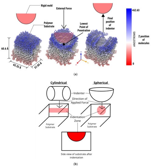
Figure 2.
(a) Schematic of overall nanoimprint lithography (NIL) process for PS. (b) Cylindrical versus spherical indenter.
2.3. Importance of Glass Transition Temperature
Choosing a suitable glass transition temperature (Tg) for the polymers is important to produce high quality imprints. Tg is identified by plotting the specific volume of the polymer as a function of temperature. When the slope changes, thermal transitions occur [42]. The literature [42] states that the Tg of PS can range from 323–373 K. Figure 3 shows that the onset of thermal transitions appeared at about 360 K and continued through about 380 K. This preliminary simulation was essential to be able to determine the Tg value for simulations.
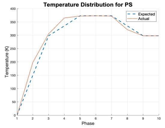
Figure 3.
Temperature distribution of molecular dynamics (MD) NIL process.
2.4. Molecular Dynamics Simulation
In this research, spherical indenters were used to deform the PS resist material. The indenters were treated as a rigid body with no adhesion interaction with the PS resist. Figure 2 presents an overview of the NIL process. The indenter was initiated at a fixed distance away from the resist (Figure 2a). After the temperature was ramped up to the Tg of PS [42], the indenter was lowered into the resist material. The indenter force, size, and initial position are parameters that govern movement of the indenter. The indenter force was varied to evaluate its effect on the deformation behavior of the polymer. Once the indenter had penetrated the resist, it continued its descent until it was held in place for a fixed duration of time. Before the indenter was removed from the resist, the temperature of the entire system was cooled down to room temperature (~300 K) [43].
The constant-energy, constant-volume ensemble (NVE) boundary conditions were applied to simulations with a time step of 0.005 fs. The units assigned to the model were LAMMPS “real.” The type of indenter used was modeled after a spherical mold. Figure 3 shows the actual temperature distribution throughout the NIL process. The simulation had an initial stabilization phase of 50,000 time steps. Temperature was ramped up to room temperature (298 K) over 15,000 time steps. Following this initial temperature rise, temperature was ramped up above the Tg of PS (373 K) for 50,000 time steps. In the next phase, temperature was kept constant at 373 K for 50,000 time steps. The indenter was lowered into the resist material while holding temperature constant at 373 K for 60,500 time steps. When the indenter reached the lowest point in the resist material, the temperature was cooled from 373 to 298 K for 50,000 time steps. After the system attained room temperature, the mold was retracted from the PS resist. Finally, after mold removal, the system was allowed to stabilize for 80,000 time steps.
The OVITO visualization program was used to analyze molecular interactions [44]. Important physical characteristics such as displacement and position of the PS molecules were used to make inferences about indentation, penetration, and recovery behavior of the resist. The results were post-processed using Microsoft Excel and MATLAB. OVITO was used to track the displacements of the polymer chains. These output metrics were exported to MATLAB, and a custom code was developed to track the molecules directly beneath the lowest point of the spherical mold and surface molecules on the top of the resist material [45].
3. Results
Molecular dynamics model results were analyzed for different indenter sizes and applied forces. Deformation behavior of PS substrate atoms for different phases of the NIL process revealed distinct patterns depending on the abovementioned process variables. Figure 4 shows a 0.9 nm thick cross-sectional view of PS resist at different phases of the nanoimprint lithography process. During the onset of indentation, the surface atoms of the resist experience deformations for different indenter sizes. The lowest point displays the lowest position of the indenter, consistent with the graphic in Figure 4b. Figure 2 demonstrates how surface atoms were affected by the size of the indenter for different applied forces. The final frame shows the resting position of the surface atoms at the end of the simulation. The 40 Å indenter with a 1 µN force displayed the deepest indentation and lowest recovery of the PMMA resist as compared to other indenters (Figure 5c). Similar trends were observed for the 30 Å indenter, wherein an increase in indenter force resulted in higher plastic deformation and consequently lower recovery of PMMA. The 40 and 30 Å indenters both show consistent deformation within the layers of the PS chains from the surface to subsurface regions. However, the 20 Å indenter had a localized indentation similar to a dimple-shaped asperity with minimal plastic deformation (Figure 4a). This is evident from the localized deformation of the PS chains on the surface layers as shown in Figure 4a for the 20 Å indenter. Higher forces had a deeper imprint for 30 and 40 Å indenters. An increase in the indenter size and force resulted in higher compaction of the PS chains, as seen in Figure 4. Indentation resulted in elongation of the polystyrene chains to accommodate the indenter without breakage of the chains. Thus, differences in indenter sizes and applied forces have a profound impact on the nanoimprinted profiles.
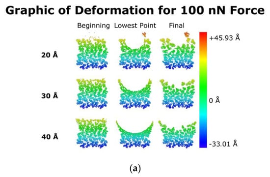
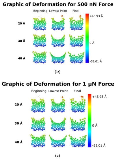
Figure 4.
Cross-sectional view of imprint at (a) 100 nN, (b) 500 nN, and (c) 1 µN of force.
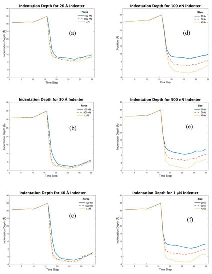
Figure 5.
Indentation comparison based on indenter size: (a) 20, (b) 30, and (c) 40 Å and indenter force: (d) 100 nN, (e) 500 nN, and (f) 1 µN.
3.1. Effect of Indenter Size and Applied Force on Indentation Depth
Indentation depth (ID) is determined by the distance that a group of surface atoms moves from their original position. In this case, ID was graphed and analyzed over the span of the entire simulation. An increase in force for each size of indenter resulted in faster descent into the material. This was particularly observed for the 40 Å indenter (Figure 5c), whereas a lower force of 100 nN was adequate to cause deformation of the resist (Figure 5d). Higher indentation forces did not reveal significant differences in deformation behavior for the 20 Å indenter (Figure 5a). Figure 5d shows a “trough-shaped” profile for lower force (100 nN) that transitions to a deeper profile for higher forces (Figure 5e,f). Thus, higher forces and large diameter indenters had deeper indentations. The 40 Å indenter with 1 µN of force caused the surface molecules to descend to the lowest point as compared to the other indenters. The surface molecules descended to the lowest position and recovered to a plateau region within the void where permanent material deformation occurred. Varying indenter size and keeping the force constant had a significant influence on the indentation profile versus keeping the indenter size constant and varying the force.
3.2. Effect on Penetration Depth
Penetration depth (PD) is defined by the average distance between the lowest point of indentation and the atoms of the top row of the resist. Penetration of each indenter size within PS can be correlated to the hoop stresses generated by external applied forces. The semi hemispherical region of the mold deforms the PS chains as they reach the Tg, thereby setting plastic deformation of the PS. Figure 6 shows that deeper penetration occurs in the substrate atoms as the force increases. For a small indenter diameter (20 Å), less penetration occurred as compared to larger indenters. However, smaller indenters can sink in the PS due to higher stress concentration based on the lower cross-section region and subsequent higher hoop stress. Higher indenter forces (500 nN and 1 µN) showed marginal differences in penetration behavior. Thus, a threshold indentation force is required to form a permanent indentation in the polymer. Larger force and larger size indenters equaled more penetration and vice versa.
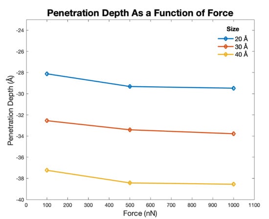
Figure 6.
Penetration depth (PD) for different indenter size and force.
3.3. Recovery Behavior
Recovery depth (RD) is the distance a group of atoms traverses from their lowest point of indentation to their final resting position. Figure 7 shows that as larger external forces are applied to the indenter, recovery depth increases. Similarly, larger indenter sizes had higher recovery depths, irrespective of the indenter force. Large force and small size lead to much less RD than indenters with small force and large size. The highest recovery depth was observed for small force and large size indenters and vice versa. This is because lower forces enable elastic recovery of the polymeric chains of PS with limited plastic deformation. In addition, larger indenter sizes displace more PS chains causing a permanent set. Polystyrene displays a localized yielding behavior called crazing in the region of maximum deformation. Localized regions of yielding display an increase in volume (dilatation) through formation of micro-cracks, which are bridged by polymeric chains. Crazing and stress whitening are the typical deformation mechanism for polystyrene. This phenomenon occurs in regions of high dilatational stress around the periphery of the spherical indenter. The above-described results provide guidelines to design NIL molds and also estimate deformation behavior of PS.
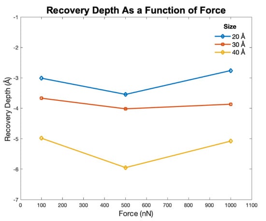
Figure 7.
Recovery depth as function of size and force.
3.4. Recovery Percentage
Recovery percentage is an internally defined element based on previously determined parameters. As the indentation force increased, recovery percentage increased. Recovery percentage (RP) is the percentage amount that a group of molecules travels from their position at the indenter’s lowest point of penetration (LP) to their final resting positions. Figure 8 shows that as the indentation force increased, recovery percentage increased. Similarly, an increase in indenter size resulted in higher recovery percentage. The lowest recovery percentage was observed for small size and large force indentation. In general, smaller indenter sizes result in the lowest RD and RP. The resist experienced similar amounts of penetration and recovery irrespective of applied force. Thus, for all the applied forces an increase in indenter size resulted in higher penetration depth, recovery depth, and recovery percentage. The 20 Å indenter penetrated the least amount into the resist and had the lowest amount of recovery. The 40 Å indenter had around 70% recovery percentage, especially for higher forces. All three indenter sizes showed similar recovery and penetration behavior regardless of the applied force. However, the shear banding deformation phenomena in polystyrene is highly temperature and rate dependent.
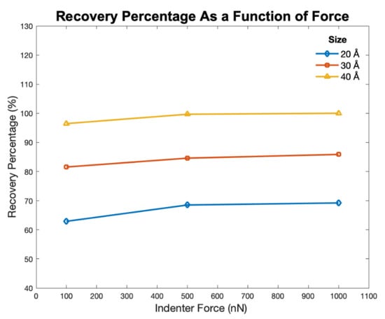
Figure 8.
Recovery percentage as a function of size and force.
3.5. Effect of Indenter Size and Indentation Hold Time
The indenter size had a significant impact on material deformation of the PS resist. As the size of the indenter increased, surface molecules experienced permanent plastic deformation. The effect of indentation time on deformation behavior was evaluated for the 30 Å indenter with an applied force of 500 nN. Figure 9 shows that an increase in indentation hold time results in permanent plastic deformation of the substrate. The original indentation hold time for all simulations was 175 fs. Herein, the polymer chains are able to recover to higher positions due to the elastic component. However, an increase in the indentation hold time to 400 fs resulted in lower recovery of the polymeric chains due to permanent plastic deformation. These findings have implications for determining the indentation hold time, which in turn can affect imprint quality for different sizes and applied forces to the indenters. Our results are consistent with findings in literature [31], wherein polystyrene displays shear banding and yield behavior in compression mode. The spherical indenter causes shear banding, which involves localized orientation of the polystyrene. Thus, an optimal hold time exists for each mold geometry, size, and material type.
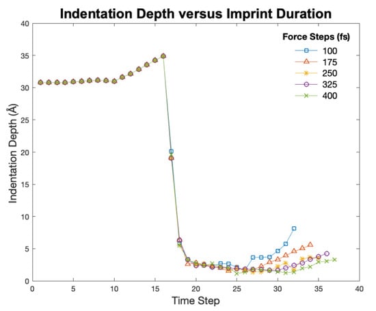
Figure 9.
Indentation profile for different time steps.
4. Conclusions
This research explains the deformation behavior of polystyrene (PS) in nanoimprint lithography based on variations in process parameters using molecular dynamics modeling. Viscoelastic behavior of PS was modeled using consistent valence force field. Different indenter sizes, forces, and imprinting durations were varied to evaluate their effect on nanoimprinting of PS. The molecular mechanism of nanoimprinting was characterized with respect to indentation depth, penetration depth, recovery depth, and recovery percentage of the polymer. For larger indenter sizes, the polymer material experienced a deeper indentation profile, more penetration, and high recovery rates. The 40 Å indenter with a 1 µN of force caused surface molecules to descend to the lowest point compared to the other indenters. Thus, varying indenter force and size provides insight into deformation behavior and thereby potential application of PS. An increase in indentation hold time beyond 250 fs resulted in higher plastic deformation of the PS. The molecular model developed in this research will be expanded to include nanoimprint lithography of other polymer composites.
Author Contributions
J.O. contributed to this original research in areas of conceptualization, methodology, software, formal analysis, investigation, data curation, and visualization. S.D. contributed in the areas of writing—original draft preparation and funding acquisition. All authors have read and agreed to the published version of the manuscript.
Funding
The authors would like to express their gratitude for funding support from the National Science Foundation Grant (NSF CMMI Award #1663128) and the Center of Excellence in Product Design and Advanced Manufacturing at North Carolina A&T State University. This research was supported by the US Dept. of Education Title III HBGI Fellowship.
Conflicts of Interest
The authors declare no conflict of interest.
References
- Chou, S.Y.; Krauss, P.R.; Renstrom, P.J. Imprint of sub-25 nm vias and trenches in polymers. Appl. Phys. Lett. 1995, 67, 3114–3116. [Google Scholar] [CrossRef]
- Chou, S.Y.; Krauss, P.R.; Renstrom, P.J. Nanoimprint lithography. J. Vac. Sci. Technol. B Microelectron. Nanom. Struct. Process. Meas. Phenom. 1996, 14, 4129–4133. [Google Scholar] [CrossRef]
- Chou, S.Y.; Krauss, P.R.; Zhang, W.; Guo, L.; Zhuang, L. Sub-10 nm imprint lithography and applications. J. Vac. Sci. Technol. B Microelectron. Nanom. Struct. Process. Meas. Phenom. 1997, 15, 2897–2904. [Google Scholar] [CrossRef]
- Akter, T.; Desai, S. Developing a predictive model for nanoimprint lithography using artificial neural networks. Mater. Des. 2018, 160, 836–848. [Google Scholar] [CrossRef]
- Crawley, D.; Nikolic, K.; Forshaw, M. 3D Nanoelectronic Computer Architecture and Implementation (Series in Materials Science and Engineering); CRC Press: Boca Raton, FL, USA, 2004. [Google Scholar]
- Gaikwad, A.; Clarke, J.; Desai, S. Atomistic Investigation of Process Parameter Variations on Material Deformation Behavior in Nanoimprint Lithography of Gold. Precis. Eng. 2020, 64, 7–19. [Google Scholar] [CrossRef]
- Kwon, B.; Kim, J.H. Importance of molds for nanoimprint lithography: Hard, soft, and hybrid molds. J. Nanosci. 2016, 2016, 1–12. [Google Scholar] [CrossRef]
- Shao, J.; Chen, X.; Li, X.; Tian, H.; Wang, C.; Lu, B. Nanoimprint lithography for the manufacturing of flexible electronics. Sci. China Technol. Sci. 2019, 62, 175–198. [Google Scholar] [CrossRef]
- Lyon, G.B.; Cox, L.M.; Goodrich, J.T.; Baranek, A.D.; Ding, Y.; Bowman, C.N. Remoldable thiol–ene vitrimers for photopatterning and nanoimprint lithography. Macromolecules 2016, 49, 8905–8913. [Google Scholar] [CrossRef]
- Odujole, J.I.; Desai, S. Molecular dynamics investigation of material deformation behavior of PMMA in nanoimprint lithography. AIP Adv. 2020, 10, 95102. [Google Scholar] [CrossRef]
- Koyama, M.; Shirai, M.; Kawata, H.; Hirai, Y.; Yasuda, M. Computational study on UV curing characteristics in nanoimprint lithography: Stochastic simulation. Jpn. J. Appl. Phys. 2017, 56, 06GL03. [Google Scholar] [CrossRef]
- Lee, H. Effect of imprinting pressure on residual layer thickness in ultraviolet nanoimprint lithography. J. Vac. Sci. Technol. B Microelectron. Nanom. Struct. Process. Meas. Phenom. 2005, 23, 1102–1106. [Google Scholar] [CrossRef]
- Jain, A.; Spann, A.; Bonnecaze, R.T. Effect of droplet size, droplet placement, and gas dissolution on throughput and defect rate in UV nanoimprint lithography. J. Vac. Sci. Technol. B Nanotechnol. Microelectron. Mater. Process. Meas. Phenom. 2017, 35, 11602. [Google Scholar] [CrossRef]
- Hirai, Y. Basic Mechanisms of Nanoimprint Lithography. Nanoimprinting Appl. 2019, 11, 83. [Google Scholar]
- Rowland, H.D.; Sun, A.C.; Schunk, P.R.; King, W.P. Impact of polymer film thickness and cavity size on polymer flow during embossing: Toward process design rules for nanoimprint lithography. J. Micromech. Microeng. 2005, 15, 2414. [Google Scholar] [CrossRef]
- Gaikwad, A.; Clarke, J. Molecular dynamics study of the quenching effect on direct nanoimprint of gold. In Proceedings of the 2019 IISE Annual Conference, Orlando, FL, USA, 18–21 May 2019. [Google Scholar]
- Odujole, J.; Desai, S. Molecular Dynamics Simulation of Poly Acrylic Acid as a Resist Material for Thermal Nanoimprint Lithography Processes. In Proceedings of the Industrial Engineers Research Conference 2020, New Orleans, LA, USA, 1 October 2020. [Google Scholar]
- Rodrigues, J.; Desai, S. The nanoscale Leidenfrost effect. Nanoscale 2019, 11, 12139–12151. [Google Scholar] [CrossRef] [PubMed]
- Marquetti, I.; Desai, S. Orientation effects on the nanoscale adsorption behavior of bone morphogenetic protein-2 on hydrophilic silicon dioxide. RSC Adv. 2019, 9, 906–916. [Google Scholar] [CrossRef]
- Gaikwad, A.; Desai, S. Understanding material deformation in nanoimprint of gold using molecular dynamics simulations. Am. J. Eng. Appl. Sci. 2018, 11, 837–844. [Google Scholar] [CrossRef][Green Version]
- Yuan, Y.; Sun, T.; Zhang, J.J.; Liu, C. Molecular Dynamics Study of Nanoimprint of Single Crystal Aluminium Thin Film. In Proceedings of the 2015 International Conference on Artificial Intelligence and Industrial Engineering, Phuket, Thailand, 26–27 July 2015. [Google Scholar]
- Lyulin, A.V.; Balabaev, N.K.; Mazo, M.A.; Michels, M.A.J. Molecular dynamics simulation of uniaxial deformation of glassy amorphous atactic polystyrene. Macromolecules 2004, 37, 8785–8793. [Google Scholar] [CrossRef]
- Lyulin, A.V.; Michels, M.A.J. Molecular dynamics simulation of bulk atactic polystyrene in the vicinity of T g. Macromolecules 2002, 35, 1463–1472. [Google Scholar] [CrossRef]
- Lyulin, A.V.; Balabaev, N.K.; Michels, M.A.J. Correlated segmental dynamics in amorphous atactic polystyrene: A molecular dynamics simulation study. Macromolecules 2002, 35, 9595–9604. [Google Scholar] [CrossRef]
- Eslami, H.; Müller-Plathe, F. Molecular dynamics simulation of sorption of gases in polystyrene. Macromolecules 2007, 40, 6413–6421. [Google Scholar] [CrossRef]
- Liu, W.; Yang, C.-L.; Zhu, Y.-T.; Wang, M. Interactions between single-walled carbon nanotubes and polyethylene/polypropylene/polystyrene/poly (phenylacetylene)/poly (p-phenylenevinylene) considering repeat unit arrangements and conformations: A molecular dynamics simulation study. J. Phys. Chem. C 2008, 112, 1803–1811. [Google Scholar] [CrossRef]
- Ayyagari, C.; Bedrov, D.; Smith, G.D. Structure of atactic polystyrene: A molecular dynamics simulation study. Macromolecules 2000, 33, 6194–6199. [Google Scholar] [CrossRef]
- Yang, F.; Ghosh, S.; Lee, L.J. Molecular dynamics simulation based size and rate dependent constitutive model of polystyrene thin films. Comput. Mech. 2012, 50, 169–184. [Google Scholar] [CrossRef]
- Pfaller, S.; Possart, G.; Steinmann, P.; Rahimi, M.; Müller-Plathe, F.; Böhm, M.C. Investigation of interphase effects in silica-polystyrene nanocomposites based on a hybrid molecular-dynamics–finite-element simulation framework. Phys. Rev. E 2016, 93, 52505. [Google Scholar] [CrossRef]
- Zharik, G.A.; Dagesyan, S.A.; Soldatov, E.S.; Presnov, D.E.; Krupenin, V.A. Nanometer Scale Lithography with Evaporated Polystyrene. Mosc. Univ. Phys. Bull. 2017, 72, 627–632. [Google Scholar] [CrossRef]
- Ma, S.; Con, C.; Yavuz, M.; Cui, B. Polystyrene negative resist for high-resolution electron beam lithography. Nanoscale Res. Lett. 2011, 6, 446. [Google Scholar] [CrossRef]
- Brazel, C.S.; Rosen, S.L. Fundamental Principles of Polymeric Materials; John Wiley & Sons: Hoboken, NJ, USA, 2012. [Google Scholar]
- Biovia, D.S. Materials Studio; Version 6.0; Dassault Systems: San Diego, CA, USA, 2012. [Google Scholar]
- Kang, J.-H.; Kim, K.-S.; Kim, K.-W. Molecular dynamics study on the effects of stamp shape, adhesive energy, and temperature on the nanoimprint lithography process. Appl. Surf. Sci. 2010, 257, 1562–1572. [Google Scholar] [CrossRef]
- Marquetti, I.; Rodrigues, J.; Desai, S.S. Ecological Impact of Green Computing Using Graphical Processing Units in Molecular Dynamics Simulations. Int. J. Green Comput. 2018, 9, 35–48. [Google Scholar] [CrossRef]
- Kwon, S.; Lee, Y.; Park, J.; Im, S. Molecular simulation study on adhesions and deformations for Polymethyl Methacrylate (PMMA) resist in nanoimprint lithography. J. Mech. Sci. Technol. 2011, 25, 2311. [Google Scholar] [CrossRef]
- Chang, K.-H. e-Design: Computer-Aided Engineering Design; Academic Press: Cambridge, MA, USA, 2016. [Google Scholar]
- Chang, Y.; Chang, S.-W. Full-atomistic simulations of poly (ϵ-caprolactone) diol models with CVFF and CGenFF. Multiscale Multiphys. Mech. 2016, 1, 327–340. [Google Scholar] [CrossRef]
- Awasthi, A.P.; Lagoudas, D.C.; Hammerand, D.C. Modeling of graphene–polymer interfacial mechanical behavior using molecular dynamics. Model. Simul. Mater. Sci. Eng. 2008, 17, 15002. [Google Scholar] [CrossRef]
- Plimpton, S. Fast parallel algorithms for short-range molecular dynamics. J. Comput. Phys. 1995, 117, 1–19. [Google Scholar] [CrossRef]
- Rocha, J.R.; Yang, K.Z.; Hilbig, T.; Brostow, W.; Simoes, R. Polymer indentation with mesoscopic molecular dynamics. J. Mater. Res 2013, 28, 21. [Google Scholar] [CrossRef][Green Version]
- Xia, W.; Lan, T. Interfacial Dynamics Governs the Mechanical Properties of Glassy Polymer Thin Films. Macromolecules 2019, 52, 6547–6554. [Google Scholar] [CrossRef]
- Brostowl, W.; Simões, R. Tribological and mechanical behavior of metals and polymers simulated by molecular dynamics. J. Mater. Educ. 2005, 27, 19. [Google Scholar]
- Stukowski, A. Visualization and analysis of atomistic simulation data with OVITO–the Open Visualization Tool. Model. Simul. Mater. Sci. Eng. 2009, 18, 15012. [Google Scholar] [CrossRef]
- Matlab, R; The MathWorks, Inc.: Natick, MA, USA, 2019.
Publisher’s Note: MDPI stays neutral with regard to jurisdictional claims in published maps and institutional affiliations. |
© 2020 by the authors. Licensee MDPI, Basel, Switzerland. This article is an open access article distributed under the terms and conditions of the Creative Commons Attribution (CC BY) license (http://creativecommons.org/licenses/by/4.0/).