Article

Hydrogen in Aluminium-Coated Steels Exposed to Synthetic Seawater

by
Shiladitya Paul
1,2
1
TWI, Cambridge CB21 6AL, UK
2
School of Engineering, University of Leicester, Leicester LE1 7RH, UK
Surfaces 2020, 3(3), 282-300; https://doi.org/10.3390/surfaces3030021
Submission received: 31 May 2020 / Revised: 23 June 2020 / Accepted: 27 June 2020 / Published: 4 July 2020

Abstract

:
Thermally sprayed aluminium (TSA) coatings provide protection to offshore steel structures without the use of external cathodic protection (CP) systems. These coatings provide sacrificial protection in the same way as a galvanic anode, and thus hydrogen embrittlement (HE) becomes a major concern with the use of high strength steels. The effect of TSA on the HE of steel seems to remain largely unknown. Further, the location of hydrogen in TSA-coated steel has not been explored. To address the above knowledge gap, API 5L X80 and AISI 4137 steel coupons, with and without TSA, were prepared and the amount of hydrogen present in these steels when cathodically polarised to −1.1 V (Ag/AgCl) for 30 days in synthetic seawater was determined. One set of TSA-coated specimens was left at open circuit potential (OCP). The study indicates that the amount of hydrogen present in TSA-coated steel is ~100 times more than the amount found in uncoated steel, and that the hydrogen seems to be largely localised in the TSA layer.

1. Introduction

Fe-C alloys (commonly called carbon steels when C <1.4 wt%) have become the workhorse of the offshore industry owing to their ease of availability, manufacturability, strength, and low cost. The strength of Fe-C alloys can be further improved by the small addition of other alloying elements such as vanadium, manganese, nickel, molybdenum, silicon, boron, niobium and chromium to make low alloy steels [1]. However, in the marine environment, these carbon and low alloy steels are prone to corrosion [2]. To mitigate corrosion, a cathodic protection (CP) system containing galvanic anodes is employed [3,4]. The application of galvanic anodes polarises the steel structure to below the protection potential, considered as −0.8 V (Ag/AgCl/seawater or approximately −0.6 V vs. standard hydrogen electrode (SHE)) at ambient, and reduces the metal loss significantly [5]. Note must be made that the current drain from the anode is an important parameter and thus the type of anode plays an important role in cathodic protection. As a side effect of CP, hydrogen is often generated on the steel surface, particularly at more negative potentials [6,7]. This hydrogen can either coalesce with other hydrogen atoms and form hydrogen gas or enter the steel as atomic hydrogen [8]. The ingress of atomic hydrogen in steel can cause loss of ductility and reduction in toughness with catastrophic consequences, particularly for high strength steels [7,9,10,11,12,13]. This is also known as hydrogen embrittlement (HE), where the components crack and fracture at stresses below the yield strength of the material.
To reduce the generation of hydrogen it is imperative to reduce the surface on which hydrogen is generated. This is generally achieved by coating the steel structure with a dielectric coating, such as organic paint [14,15]. The presence of a dielectric paint reduces the current demand, thus reducing the kinetics of hydrogen generation, and allowing the anodes to last longer. The paints also act as a barrier when intact, protecting the structure from the corrosive marine environment even in areas where CP is not effective [16]. However, with exposure time, paints degrade and their barrier properties deteriorate, resulting in seawater ingress and an increase in anode consumption [17]. In areas where the electrolyte layer is not always present, these coatings when damaged offer little or no protection. To overcome some of the issues associated with paints, the offshore industry has resorted to thermally sprayed sacrificial coatings. One of the earliest applications of such coatings in an offshore platform dates back to the 1980s in the North Sea [18]. Several other applications have also been reported suggesting the use of thermally sprayed aluminium (TSA) in the submerged zone and painted Zn-Al alloys in the atmospheric zone. A review of this topic can be found elsewhere [19].
Thermally sprayed coatings of aluminium and their alloys provide protection to steel in a similar way to that of anodes because of their position in the galvanic series (in seawater). In addition, these coatings also act as a barrier when intact. If these coatings are damaged in service, the proximity of the anodic coating allows the steel in the damaged region to remain cathodically polarized and hence protected as long as a layer of electrolyte (seawater) is present [20,21,22,23,24,25]. The cathodic polarisation of steel in the damaged region also results in the localised increase in pH. The localised increase in pH at the steel-seawater interface is brought about by the cathodic reactions, such as reduction of dissolved oxygen or water. This in turn causes deposition of calcareous matter, such as Ca- and Mg- containing minerals (which are present in abundance in seawater) in the damaged region thereby providing additional protection [5,20,26,27].
It is evident from the above that TSA coatings can provide protection to offshore steel structures without external galvanic anodes or other CP systems [18]. However, most of the steel structures currently protected by TSA have been fabricated from lower strength grade steels primarily due to HE concerns. HE becomes more severe as the strength of the steel increases [7,12,28,29,30]. The very microstructures that give some carbon and low alloy steels their strength also results in their embrittlement. There are very few studies elaborating the effect of sacrificial aluminium coatings on the HE of steels [31,32,33]. The limited studies found in literature focus on the embrittlement behaviour and not on the levels of hydrogen. The location of hydrogen in coated steel also seems to remain largely unknown with an assumption that they are in the steel.
This study addresses the above knowledge gap and experimentally determines the amount and location of hydrogen in TSA-coated steels (API 5L X80 and AISI 4731) when exposed to seawater. The amount of hydrogen present in these steels when cathodically polarised to −1.1 V (Ag/AgCl saturated KCl) is also presented.

2. Materials and Methods

2.1. Specimen Preparation
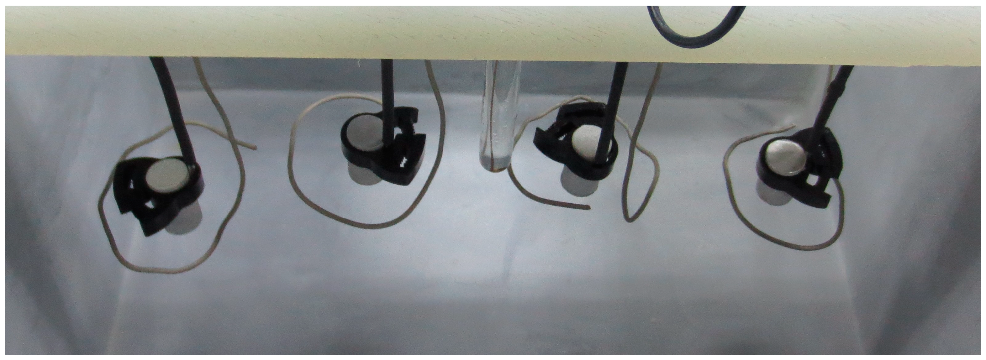
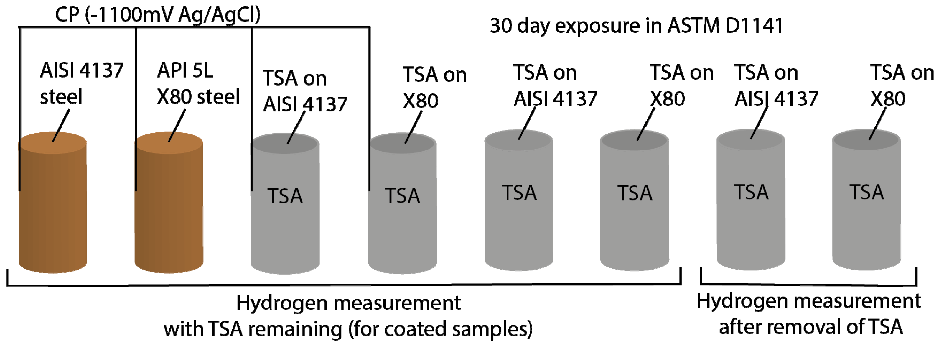
Two different grades of steel pipes (API 5L X80 and AISI 4137) were acquired and machined into rods of 1 cm diameter and 2 cm length. These were sprayed with commercially pure aluminum using a twin-wire arc spray system (TWAS) with a 528 gun (Metallisation Ltd., Dudley, UK). Table 1 shows the composition of steels and Al wire, while Table 2 gives the parameters used for the coating production. All surfaces (curved, ends and edges) of the steel coupons were coated with TSA. Both coated and uncoated specimens were prepared to study the effect of TSA.

2.2. Exposure Tests

The specimens were examined and any over spray was removed. They were cleaned with acetone and electrical connections were made on some of them for cathodic charging or potential measurements. A simple three-electrode arrangement was used for external cathodic polarization (ECP). The specimens were made the working electrode with Pt-Ti wires as the counter electrode. In all cases, Ag/AgCl (saturated KCl) system was used as the reference electrode. All potentials reported against Ag/AgCl (saturated KCl) in this paper. The coated and uncoated specimens were placed in a tank and 30 L (litres) of ASTM D1141 synthetic seawater (without the heavy elements) was poured into it [34]. The composition of synthetic seawater used can be found in Table 3.
All uncoated steel specimens and a set TSA-coated steel specimen were polarized to −1.1 V (Ag/AgCl/Saturated KCl or −0.9 V SHE) at 21 °C by using a potentiostat (VMP 300, Bio-Logic, Seyssinet-Pariset, France). The TSA-coated specimens were polarized to see the effect of stray or accidental CP on TSA-coated offshore steel structures. The specimen arrangement for ECP is shown in Figure 1.
The synthetic seawater used for the test was replaced once a week. The pH was not monitored as previous work suggested that weekly replenishment would be sufficient to keep the bulk pH to 8.0 ± 0.2 [6,21,35]. After completion of the 30-day exposure, the specimens were removed from the seawater tank. The electrical connection in the case of some specimens removed carefully before further cleaning. All the specimens were washed with deionized water and dried using a paper towel. One set of specimens were taken for visual and microstructural studies and the other set was stored in a liquid nitrogen dewar. The time between the removal of the specimens from the seawater tank and their storage in the liquid nitrogen dewar was kept to a minimum. The testing regime is schematically shown in Figure 2.

2.3. Visual and Microstructural Examination

Some specimens were examined visually and prepared for microstructural observation. The visual examination was carried out with a travelling microscope. After visual examination, the specimens were cross-sectioned, mounted in a conductive resin, ground and polished to 1 micron finish with colloidal silica. Microstructural observations were carried out, first, with a light microscope and then with SEM/EDX (after gold coating).

2.4. Hydrogen Measurements

The set of specimens kept in the liquid nitrogen dewar was taken out and any deposit or residue was removed. The specimens were degreased in acetone and weighed before hydrogen measurements. The TSA in some specimens was removed after exposure by filing and wire brushing with intermittent return to the liquid nitrogen container, to minimize loss of hydrogen, before degreasing in acetone and weighing. Visual examination was carried out using a travelling microscope to ensure full removal of TSA. Diffusible hydrogen was measured at 400 °C for 20 min by using a G4 Phoenix hot extraction analyser (Bruker, Karlsruhe, Germany). The specimen was placed in a tube and heated to 400 °C for 20 min. The evolved gases were carried by high purity nitrogen (99.999%) to the thermal conductivity detector (TCD) after passing through oxygen and water absorber.

3. Results

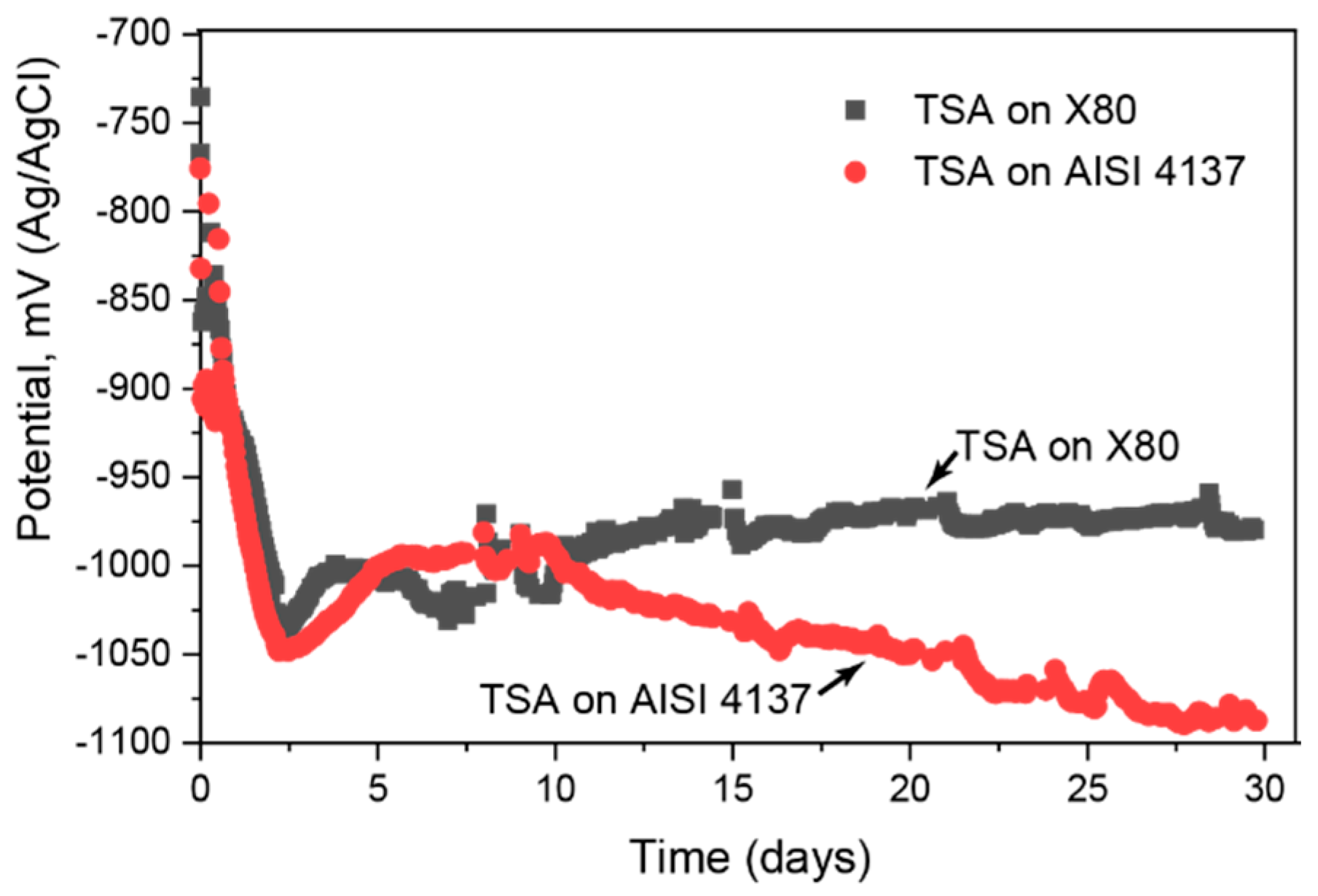
3.1. Electrochemcial Measurements

The open circuit potential (OCP) of TSA coatings on two steels is presented in Figure 3. The OCP of TSA on the two steels are similar in the first few days of immersion in synthetic seawater. In both cases the OCP decreases with time, reaching values close to −1050 mV (Ag/AgCl/saturated KCl) after two days and then slowly increasing (becoming less negative) up to day 5. Beyond a week/10 days of exposure the coatings on two steels begin to show divergence. The OCP of TSA on AISI 4137 steadily decreases with time up to 30 days, while the OCP of TSA on X80 increases with time. At the end of the test, the OCP values were −980 mV and −1080 mV for TSA-coated X80 and TSA-coated AISI 4137, respectively.

3.2. Visual and Microstructural Observations

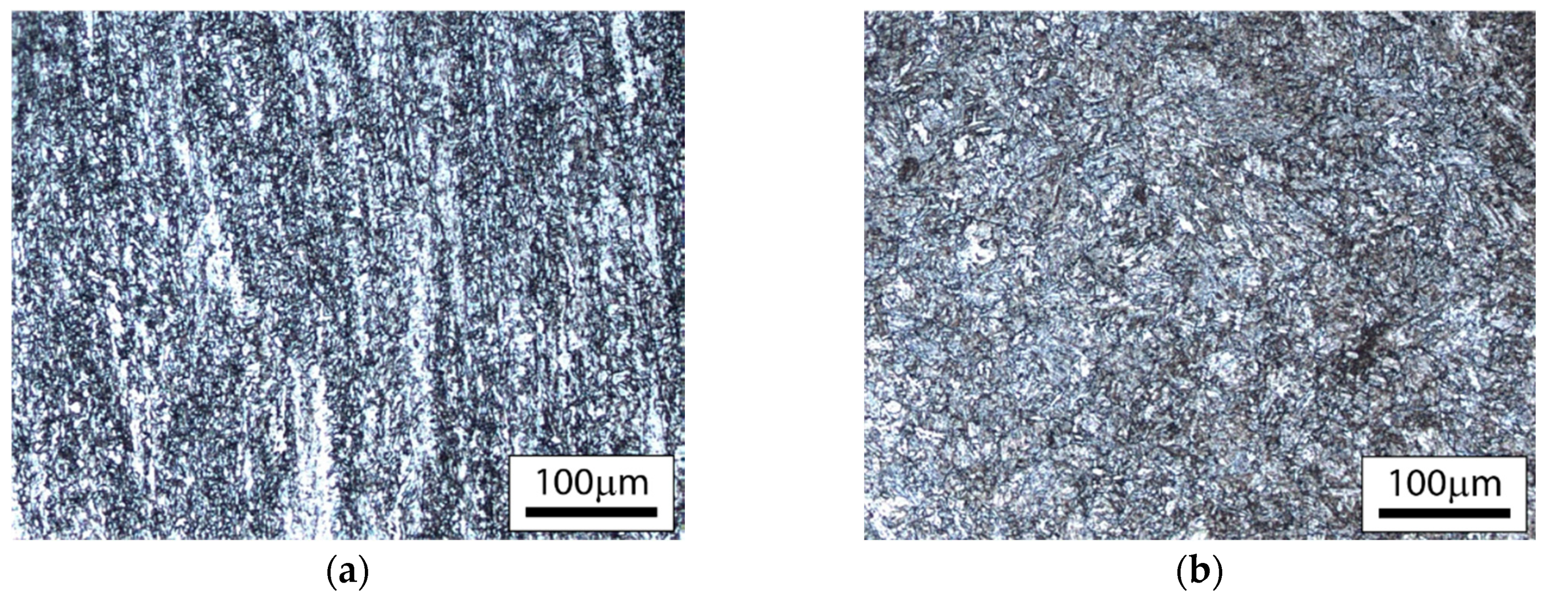
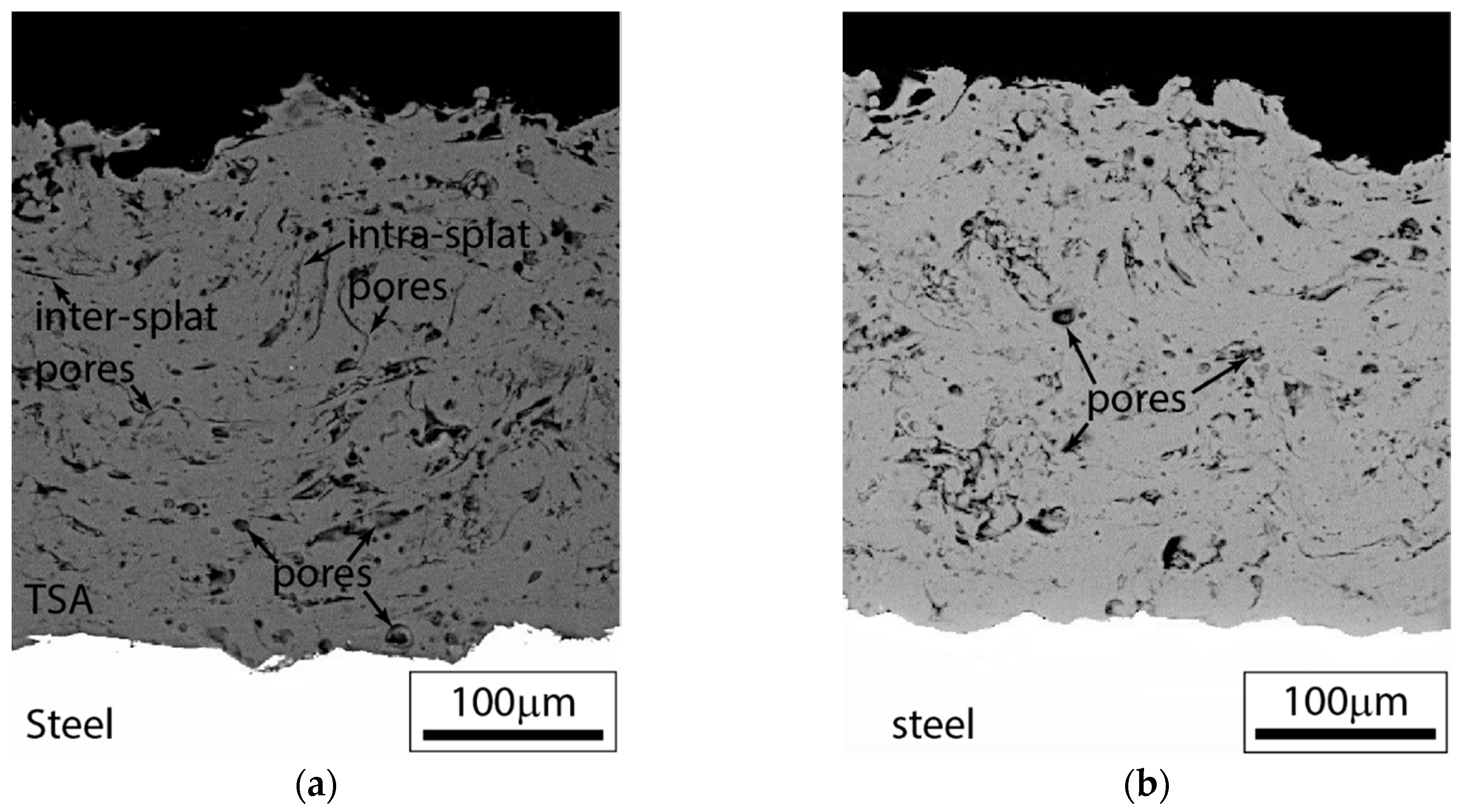
3.2.1. Substrate and Coating Microstructure

The microstructure of the steels used for the study are presented in Figure 4. API 5L X80 steel is primarily ferritic, while AISI 4137 has a bainitic microstructure. These steel microstructures do not impart any significant difference in the microstructure of the coatings, as seen in the cross-sections (Figure 5).
It is evident from the cross-section of the coated steel that TSA is porous with different pore morphologies. Some pores are globular in nature, while others are crack-like. The interface between the steel and the TSA shows good contact with no delamination. The top surface has a rough topology. This implies that the actual surface area of the coating available for reaction is greater than the geometrical surface area.

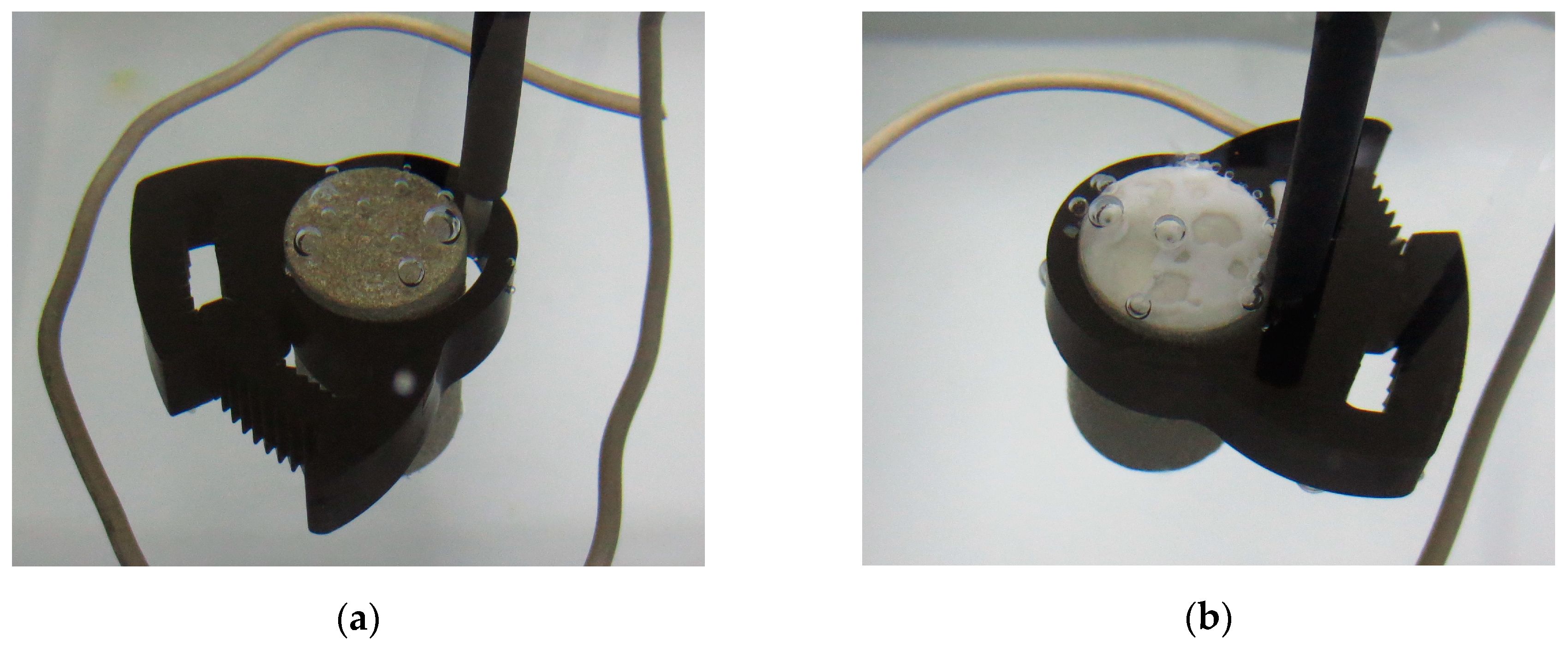
3.2.2. Visual Observations during Testing

The specimens while immersed in synthetic seawater had gas bubbles emanating from the surface on the application of ECP (Figure 6). The bubbles were observed in both uncoated and TSA-coated specimens. No or very limited gas bubbles were seen on the Pt-Ti counter electrode.
The uncoated specimens showed the growth of a film, which with time developed into a white deposit. The white deposit was seen on all exposed surfaces of the uncoated specimens (Figure 6). The TSA-coated specimens under ECP also had some changes to the visual appearance, but the deposit on the surface was less pronounced. Only some white specks were seen in these specimens. There were no marked differences between the appearance of the TSA-coated specimens that were left at open circuit potential (OCP) and those under ECP.

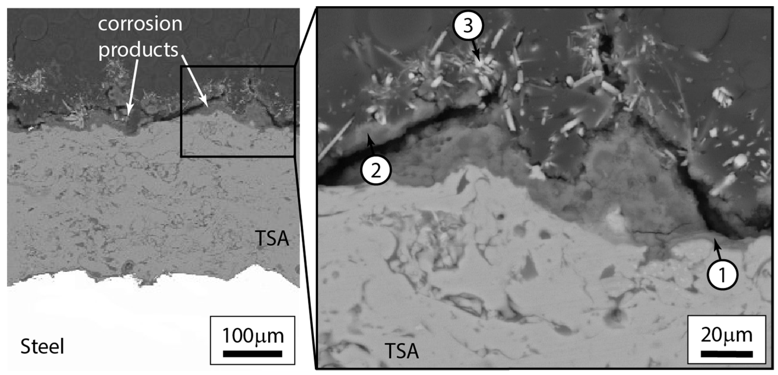
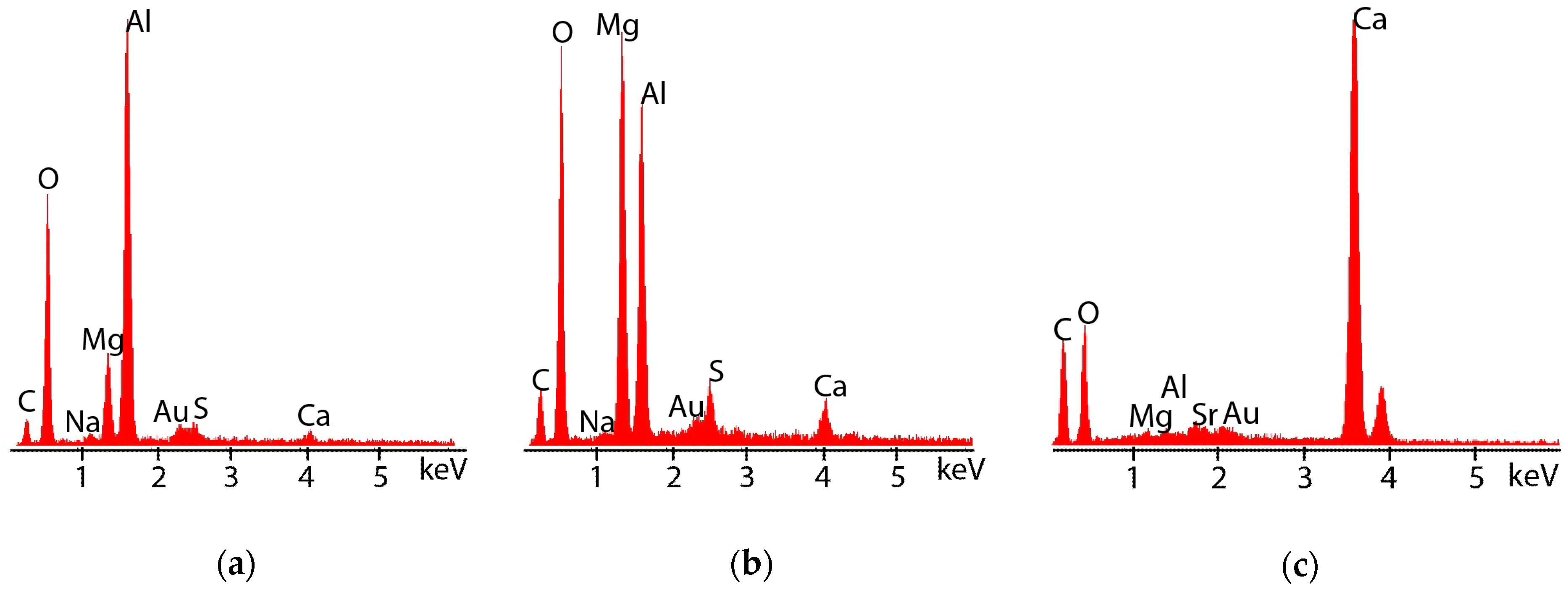
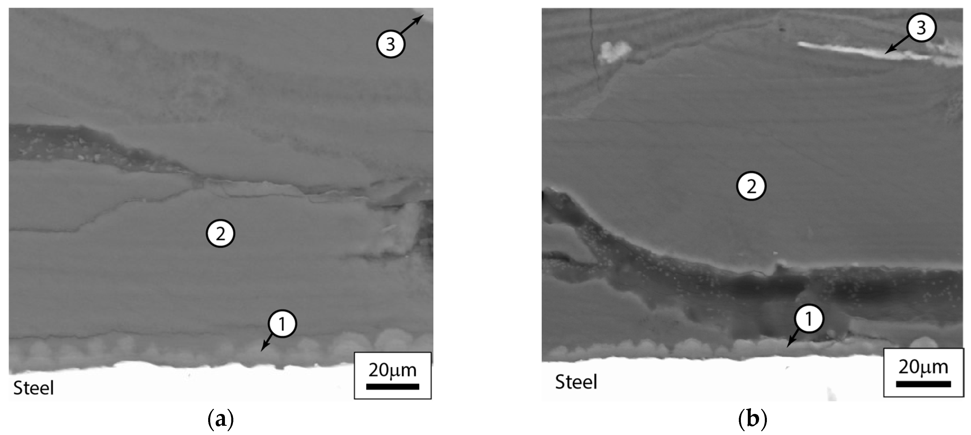
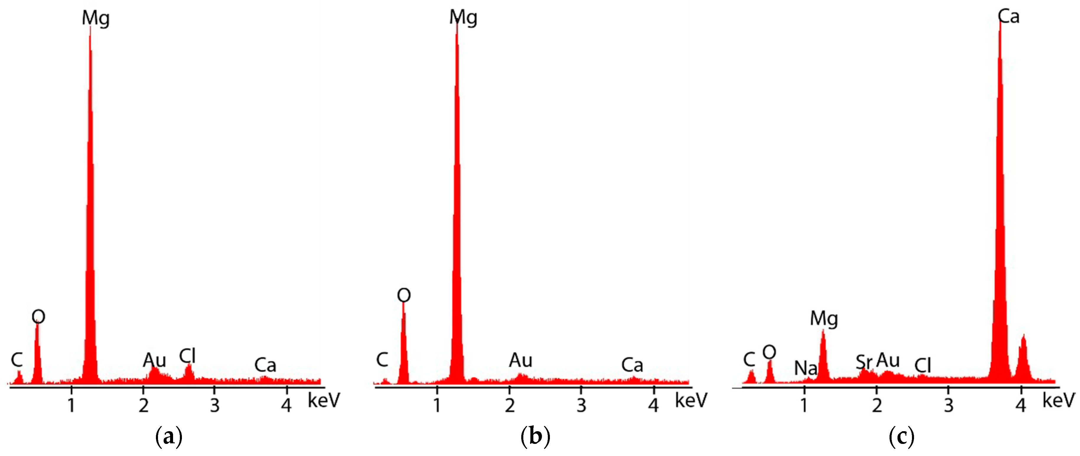
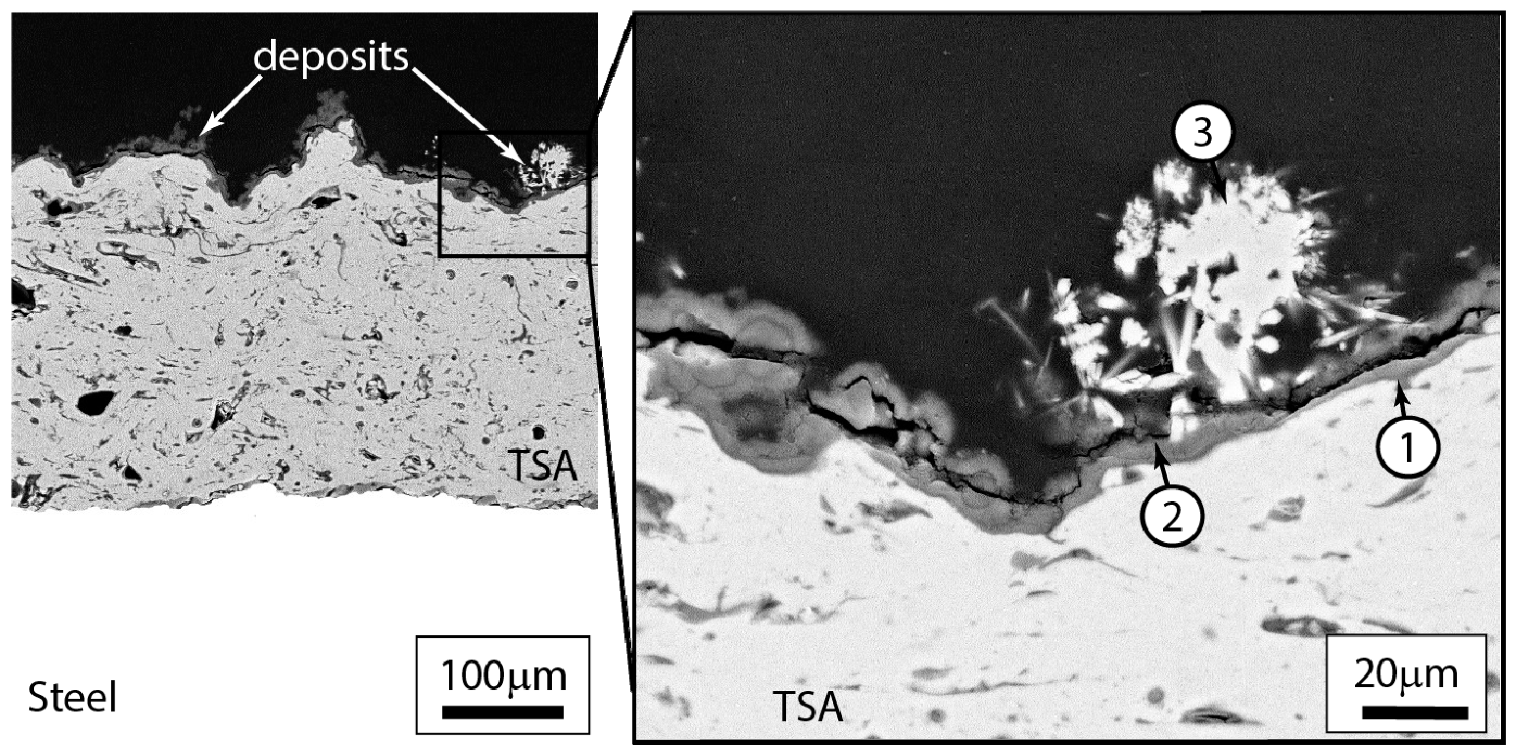
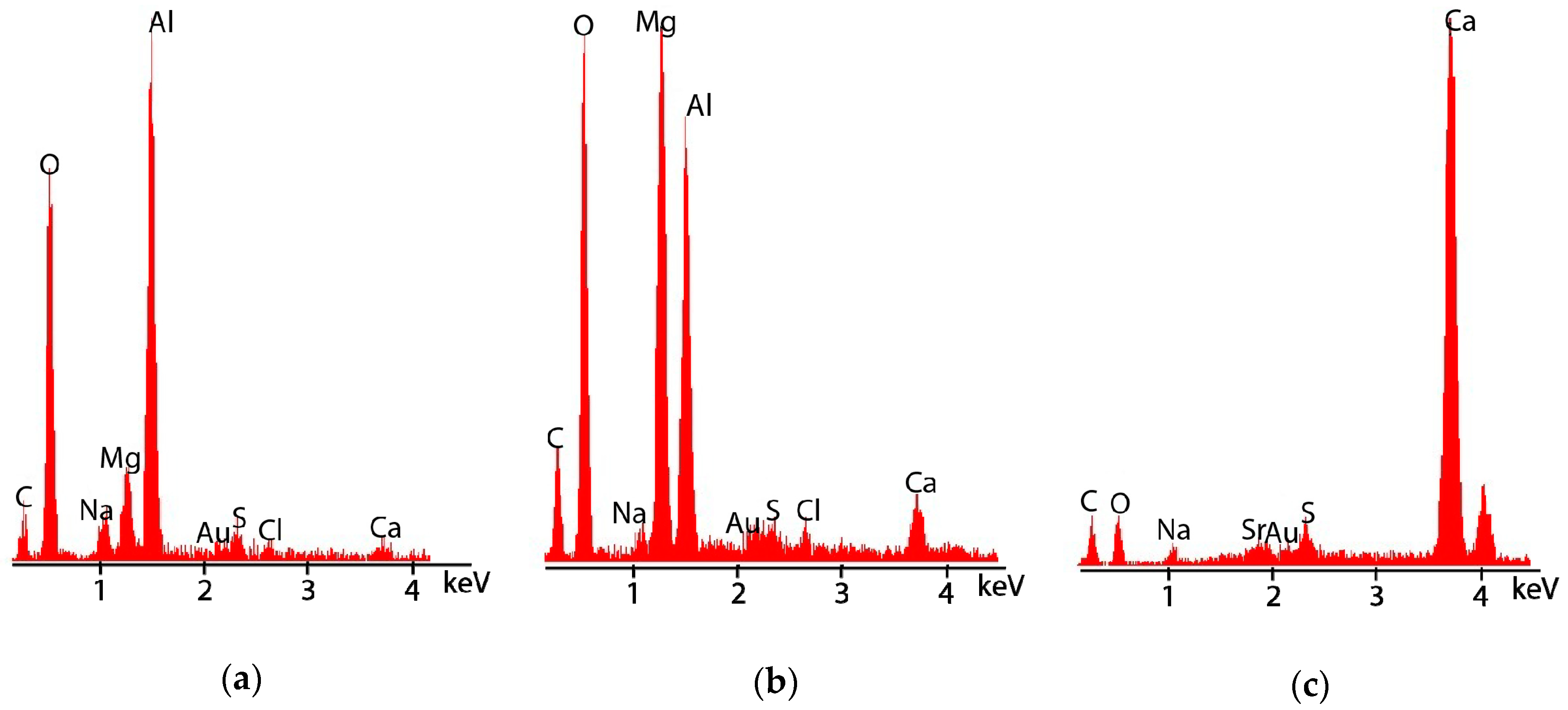
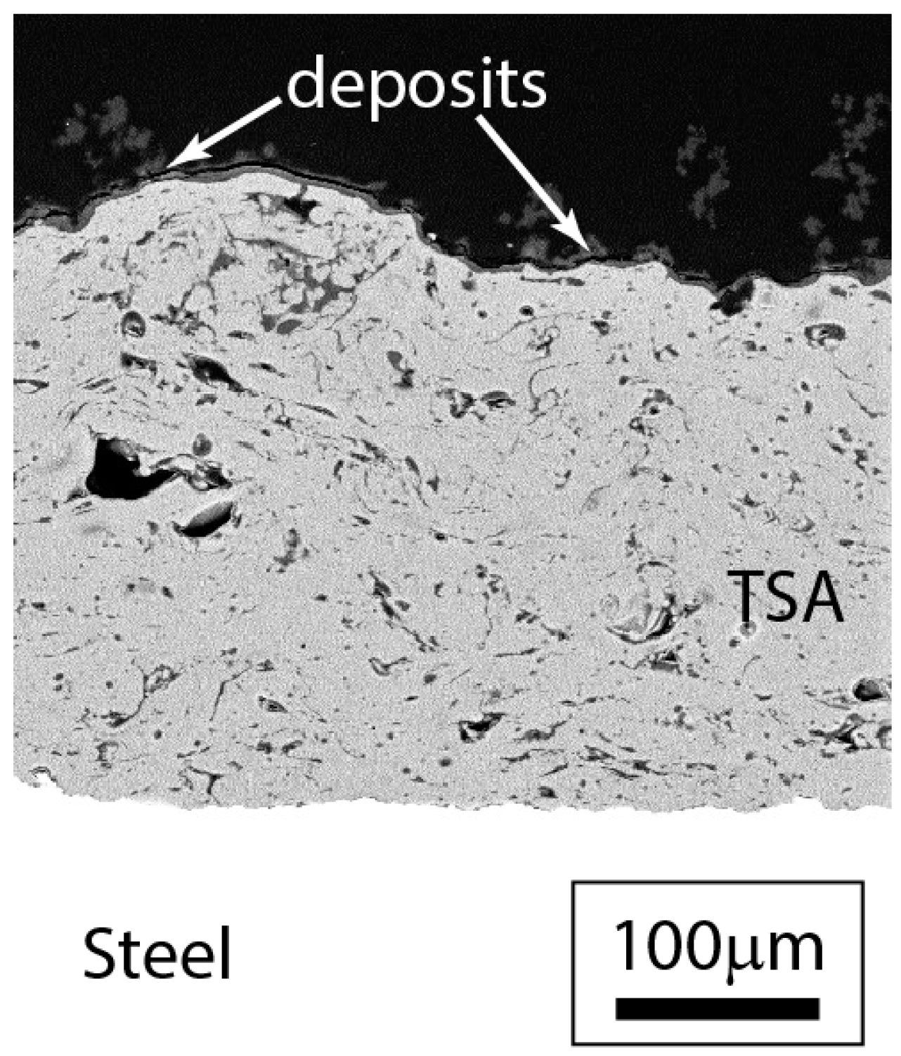
3.2.3. Post-Test Microstructural Observations

The morphology of the adherent white deposit found on the cathodically polarized X80 and AISI 4137 steels was very similar (Figure 7). There was a layer (5–10 µm) adjacent to the steel with ‘cloud-like’ appearance (Figure 7a,b). This layer is marked as region 1 in Figure 7a,b. This layer was followed by a more uniform layer (region 2) that contained cracks, pores and channels (Figure 7a). One such channel, about 20 µm in width, is clearly visible in Figure 7b. There were some ‘white’ specks away from the steel surface (region 3 in Figure 7).
The EDX spectra of the three regions in Figure 7b are shown in Figure 8. The regions marked 1, 2 and 3 in both Figure 7a,b had very similar EDX patterns. It is evident that the regions close to the steel substrate are rich in Mg and O (Figure 8a,b), while the ‘white’ specks (region 3) are rich in Ca (Figure 8c). The inherent differences in the contract due to differences in atomic number is understandable in backscattered electron (BSE) imaging. Ca (20) with higher the atomic number than Mg (12) appears brighter in the image.
The TSA-coated steel specimens kept at OCP showed ‘grey’ appearance after completion of the test. The microstructure of cross-section of TSA on X80 is shown in Figure 9. The microstructure of the coatings on the two different steels were similar. It is evident from Figure 9 that the dull surface appearance of TSA is due to the formation of corrosion products. The pores present in the TSA also seems to have corrosion products. The detailed micrograph shows three distinct areas (based on contract and morphology): (i) layer on top of TSA surface, (ii) a layer between the first corrosion product layer and the ‘white’ deposits, and (iii) a layer often containing needle-like ‘white’ deposits.
The layer adjacent to the TSA (region 1, Figure 9) contained predominantly Al, O and Mg, in conjunction with other elements such as C, Au, S, Ca and Na (Figure 10a). The layer slightly further away (5–10 µm) from aluminium layer seems to have a lot more Mg and O, with Al (Figure 10b). The ‘white’ needle-like structures seen on top of the corrosion product layer away from the aluminium layer contained Ca, C and O as the dominant elements. Other constituents of seawater were also detected and Au was present in all the EDX patterns as the specimens were gold coated.
The TSA-coated specimens polarized to −1100 mV (Ag/AgCl/saturated KCl) showed some regions with white specks. There were two different shades of white deposits. One uniformly distributed and the other speckled on the surface of TSA. The cross-section of the TSA-coated X80 clearly shows the corrosion products on the TSA surface (Figure 11). The pores present in the TSA layer also seems to have some corrosion products. Like the TSA-coated steel specimen at OCP, this specimen also shows three types of deposits. However, the ‘white’ deposit in the case of cathodically polarized TSA is more pronounced in some regions.
The deposits on top of polarized TSA were analysed using SEM/EDX (Figure 12). It would appear that the region adjacent to the aluminium layer (region 1, Figure 11) is similar in composition to that in the TSA coating at OCP. The main constituents of this layer were Al, O and Mg, with other constituents of seawater (Figure 12a). The region 2 in Figure 11 is also similar to region 2 in Figure 9. It consists of Mg, O and Al as the main constituents (Figure 12b). The ‘white’ deposits found in some places on the surface of TSA were found to predominantly contain Ca, C and O (Figure 12c).
Similar features were also seen on the surface of TSA-coated AISI 4137 kept at -1100mV (Ag/AgCl/saturated KCl). The cross-section of this coating showed some deposits (Figure 13). The presence of these deposits imparted a grey-white colour. In general, all TSA-coated specimens had Al- and O-containing compounds. The difference between the elemental composition of the deposits on TSA-coated specimens at OCP and those under ECP was not significant. Both specimens showed the sporadic presence of Mg- and Ca-containing minerals on top of the Al/Al-O layer.

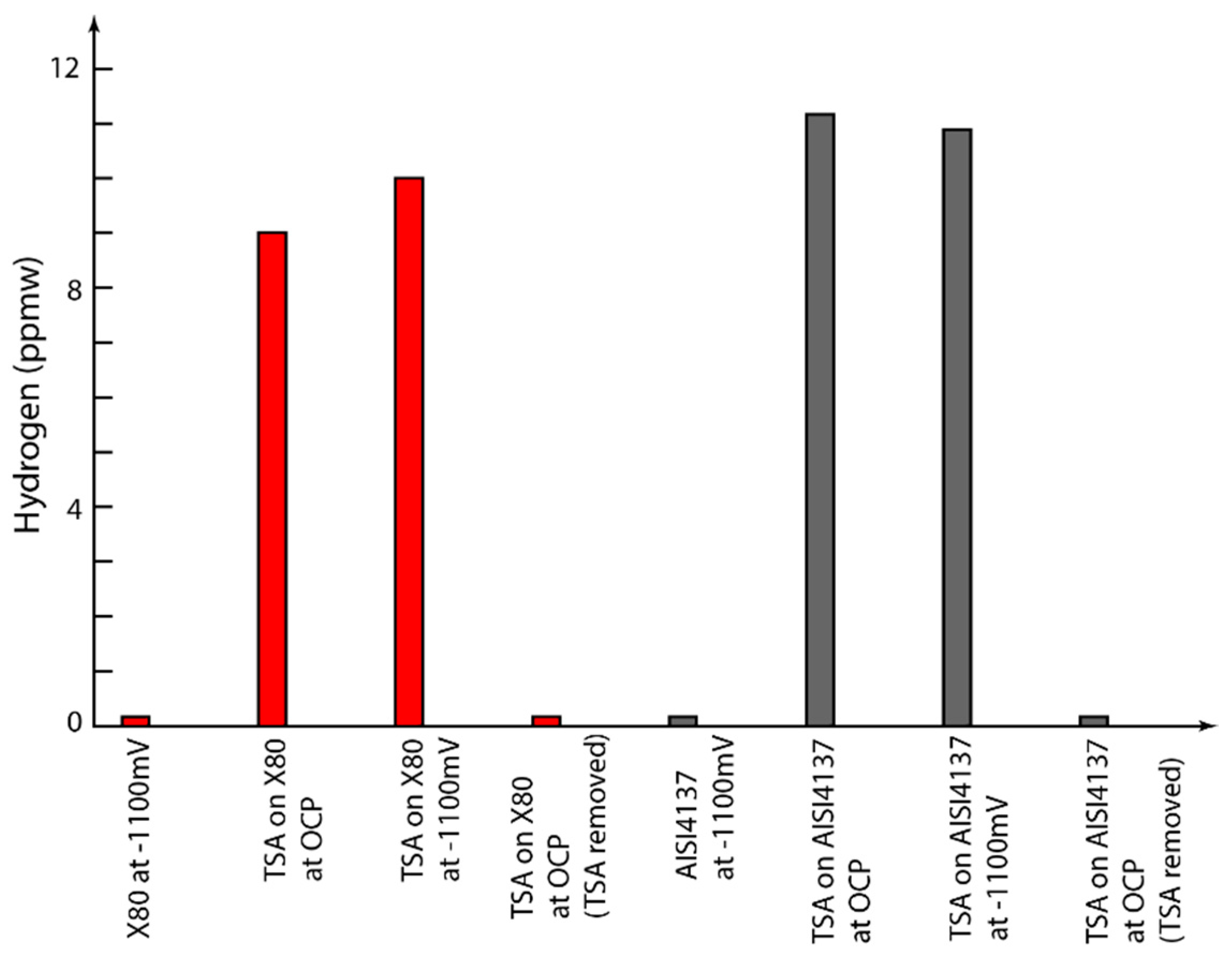
3.3. Hydrogen Measurements

The levels of diffusible hydrogen, measured using the hot extraction method, are presented in Figure 14. The effect of polarization by TSA, both with and without ECP is evident in the hydrogen measurement data. The TSA-coated steel samples show significant increase in the hydrogen content, increasing from ≤0.1 ppmw for uncoated steels to ~9–11 ppmw for TSA-coated steels. The TSA-coated X80 steel showed hydrogen content between 9–10 ppmw, while the TSA-coated AISI 4137 showed values of ~11 ppmw. The difference in the amount of hydrogen in the two different coated steels is not entirely clear, but the difference in OCP might have an effect.
The results are from a limited number of samples and, hence, should be treated with caution before drawing any broad conclusions. The minimum measurable hydrogen concentration by the analyser is 0.05 ppm with an accuracy of ±0.05 ppm.
The hydrogen content in the coated samples seems to be associated with the TSA. Once the TSA coating was removed after exposure, the hydrogen content returned to the levels found in uncoated steels.

4. Discussion

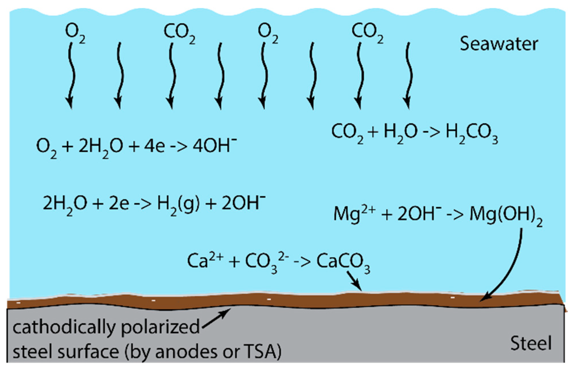
4.1. Mechanism of Hydrogen Generation

During cathodic protection, the structure to be protected is made a cathode by polarizing it. Due to polarization, the cathodic reactions occur predominantly on the surface made the cathode, which in our case in the steel or the TSA-coated steel under ECP. The steels in TSA-coated specimens kept at OCP also have some in-situ cathodic polarization due to the action of the aluminium coating. In any case, the anodic reaction is either the dissolution of Al when the TSA-coated steel is at OCP, or the generation of Cl2/O2 gas when the steel is under ECP, depending on the applied potential, anode and pH [36,37,38]. However, as the seawater has ~0.6 M Cl the generation of Cl2 is unlikely at seawater pH and at the applied potential used in this study. This is because unlike oxygen evolution reaction (OER), the equilibrium potential for chlorine evolution reaction (CER) does not depend on pH. At near-neutral pH, CER requires a potential ~0.5 V higher than that of OER [39,40].
The anodic reactions occurring in the TSA-coated steel under ECP can be the dissolution of Al if the ECP is less negative than the OCP of TSA, or evolution of O2 gas if the ECP is more negative than the OCP of TSA. In the current study the potential of TSA-coated steel was found to be less negative than −1.1 V (Ag/AgCl/saturated KCl) throughout the test for both specimen types. Hence, one would expect TSA to be somewhat protected. However, the dissolution of TSA could still occur by cathodic corrosion which is explained later.
The cathodic reactions play an important part in the hydrogen generation and calcareous deposit formation. We will discuss the mechanism of calcareous deposition in Section 4.3. Depending on the level of cathodic polarization, the cathodic reactions involve either the reduction of dissolved oxygen or oxygen reduction in conjunction with the generation of hydrogen. At higher negative potentials, the oxygen reduction reaction (1) gets surpassed by the reduction of water to produce hydrogen (2):
O2 + 2H2O + 4e → 4OH
4H2O + 4e → 2H2 + 4OH
The evolution of H2 consists of two distinct pathways in which protons become adsorbed to the surface in a series of reactions, known as the Volmer–Tafel–Hetrovsky reactions respectively [41]. At pH8, the amount of H+ (or H3O+) present in water is ~10−8 M. This can be reduced as follows to give hydrogen:
H+ + e ⇌ Hads
2Hads⇌ H2
Hads + H+ + e ⇌ H2
When the overpotential is zero the reactions go in both directions at the same rate and the electrode is at its reversible potential. Overpotential is the additional potential required to drive the reactions in a direction at a specific rate. When the coverage of the cathode is too high protons discharge onto adsorbed Hads, reaction 5. Additionally, the hydrogen may penetrate into the metal, either steel or TSA:
Hads ⇌ Habs
After reaction 3, either reaction 4, 5, or 6 takes place and is highly dependent on the surface and its effect on hydrogen mobility within the double layer at the metal electrolyte interface. The rate of the adsorption step, reaction 3, is also dependent on the metal–hydrogen (M–H) bond strength and the substrate material [42].
The mechanism of hydrogen generation in TSA is a bit more complex. Under the ECP, macroscopic hydrogen generation has been observed at −1.1 V (Ag/AgCl/saturated KCl). This level of ECP also facilitates an increase in pH near the TSA surface due to reactions 1 and 2. According to the Pourbaix diagram of aluminium, such increase in pH can lead to the dissolution of the air-formed oxide thereby leading to the exposure of the fresh aluminium surface to seawater, which enables the generation of hydrogen.
The rate of Al corrosion is known to increase with an increase in cathodic polarization, a phenomenon referred to as cathodic dissolution or cathodic corrosion [43,44,45,46,47]. The overall Al dissolution reaction is given in Equation (7), which is generally summarized as the combination of reactions given in Equations (2), (8) and (9):
Al + 4H2O + e → Al(OH)4 + 2H2
Al + 3OH → Al(OH)3 + 3e
Al(OH)3 + OH → Al(OH)4
The dissolution of Al is controlled by the layer of oxide/hydroxide of Al formed on the TSA surface. For the sake of simplicity this has been assumed to be Al(OH)3 in reactions (8) and (9), although other Al-O compounds, such as AlOOH and Al2O3 are also possible. Serdechnova et al. [44] reported a stoichoiometry of 4.62 ± 0.22 hydroxides per dissolved Al ion for pure Al.
In addition to the above, the air-formed oxides on aluminium (TSA) surface can be damaged by chloride solutions such as synthetic seawater (~0.6 M Cl), which expose the underlying metallic Al. The localized depassivation facilitates local hydrogen evolution, generating ‘superfluous’ hydrogen [48]. Thus, the damage or removal of the oxide film, be it by the localized alkalization or by Cl ions, can result in the generation of ‘superfluous’ hydrogen evolution in Al.
In addition to the material property of Al, the pore architecture of TSA possibly plays a part in hydrogen generation as the cathodic (and anodic) reactions occur on the surface. In thermal spray process, molten or semi-molten droplets impinge on the substrate (or previously deposited consumable) surface and they spread, solidify and form a coating [49]. This process generates a network of porosity and voids (Figure 5). The pore network allows the TSA to have a large internal surface area where, once the seawater enters, cathodic generation of hydrogen could occur under ECP. Some of the pores might be surface-connected allowing the electrolyte to be in contact with the steel and TSA concurrently. This would allow cathodic polarization of steel and hence possible generation of hydrogen on steel surface in TSA-coated steel at OCP.

4.2. Location of Hydrogen in TSA-Coated Steel

The hydrogen content in TSA-coated steels was two orders of magnitude (×100) greater than that of the uncoated specimens. At a first glance, this increase would seem to be due to the presence of TSA and one might assume that the hydrogen is still in the steel substrate. However, from the results of the hydrogen measurements from the TSA-coated steels (after removal of TSA just before hydrogen measurements), it is evident that the hydrogen is present in the TSA layer.
One may argue that the presence of moisture in the TSA or absorbed moisture in aluminium corrosion products affect the hydrogen measurement [50]. This, however, is unlikely as the gases and vapours evolving from the specimens during hot extraction were passed through several reactor tubes to absorb compounds that may interfere with the hydrogen measurements. One such reactor tube contained moisture absorbent. In previous experiments carried out in the same laboratory, the same approach was used for the measurement of hydrogen without erroneous data [6].
The levels of hydrogen found in the steels tested were below 0.1 ppmw. This is similar to the levels reported in literature [51]. The difference between the levels of hydrogen in the two steels is rather small. This could be due to the difference in the microstructure: API 5L X80 steel is primarily ferritic, while AISI 4137 has a bainitic microstructure [52]. This can also be seen in Figure 4. The difference in the amount of hydrogen in the coated steels is unlikely to depend on the solubility of hydrogen in the steel as the steel only contributes to <1% of the total hydrogen.
It is evident that the Al coating plays an important role in hydrogen retention. The diffusivity (D) of hydrogen in Al at 21 °C is ~1.5 × 10⁻¹⁰ cm2s−1 [53]. By assuming that the diffusion distance is ~ Dt , we get a diffusion distance of ~0.2 mm for the 30-day test. Given that the thickness of the TSA coatings used were ~0.2–0.3 mm, it is likely that the coatings were reaching hydrogen saturation. This might explain the similar levels of hydrogen in all coated samples, with TSA-coated AISI4137 showing slightly more hydrogen possibly due to more active OCP. This, however, does not resolve another issue related to the amount of hydrogen. Unlike in its molten state, the solubility of hydrogen is aluminium is limited at room temperature [54]. The values reported in literature suggest a solubility of ~1.5 × 10⁻¹² atomic fraction [55]. This is significantly lower than the measured hydrogen levels in the TSA-coated steels.
It is known that the solubility of hydrogen can be altered significantly by sites present in the material that trap hydrogen. These trapping sites could be lattice vacancies, dislocations, grain boundaries, inclusions, precipitates etc. Sometimes certain types of solute atom clusters can also trap hydrogen [55]. The presence of these defects in TSA cannot be ruled out. As the coating process introduces mechanical stresses (due to high cooling rates and thermal expansion mismatch between the aluminium and steel), there may be deformation-related defects (e.g., dislocation arrays, interparticle boundaries, etc.) in these coatings [56]. Because of the above, the amount of hydrogen in TSA-coated steel is significantly more than expected. The subtle differences in the physical properties of the two steels, such as Young’s modulus, thermal expansion coefficient and surface composition might have contributed to slightly different defect type, concentration and distribution, and hence different hydrogen concentrations.
Although a difference in the hydrogen content of steels under ECP and steels with TSA was found in the study, it is not clear if this would negatively affect the performance of these coated steels in service. Both these steel grades are considered ‘high strength’ so one may assume that they are prone to hydrogen embrittlement (HE). However, numerous studies have eluded to the importance of microstructure in the HE process [7,13,30,51,52,57,58]. Yet, no agreement can be found in literature on the role of different microstructural constituents. Some researchers suggest that microstructures containing higher hydrogen trapping sites are more effective in reducing the HE susceptibility because less diffusible hydrogen is present and it is assumed that the diffusible hydrogen is the main factor influencing the susceptibility of material to HE [59,60]. Others have concluded that higher trapping efficiency imparted by lower diffusivity of hydrogen in the steel microstructure increases the vulnerability of the steel to HE [61]. Thus, the contradictory reports make it difficult to suggest the effect of the hydrogen on the two steels studied. However, Zhang et al. [62] reported HE index of 35% and 45% for X80 steels when tested at potentials of −1055 mV and −1155 mV (Ag/AgCl/saturated KCl) in deaerated seawater at a strain rate of 10−6 s−1. This study gives some indication of the HE potential of X80 in deaerated seawater under ECP, but it does not give any information on the propensity of HE when coated with TSA. It is unclear if the hydrogen deemed to be present in the TSA layer/Steel-TSA interface will cause HE of X80 and/or AISI 4137 in natural seawater service. Nonetheless, it is clear from the above that understanding the combined effect of steel microstructures, TSA, hydrogen and applied stress on the susceptibility of steels to HE is complicated and needs further research.

4.3. Influence of Calcareous Deposits

During cathodic polarization of a metal, the metal surface is compelled to host the cathodic reactions. These reactions (1) and (2) generate hydroxyl ions [OH], which increase the pH at the cathodically polarized metal-seawater interface. In this paper, the cathodic polarization was brought about by TSA or ECP. The reactions of carbonate, bicarbonate, and magnesium ions in seawater (7–9) and the reduction in solubility due to increased pH results in the formation and precipitation of calcareous matter on the cathodically polarized steel surface:
OH + HCO3 → H2O + CO32−
CO32− + Ca2+ → CaCO3
Mg2+ + 2OH → Mg (OH)2
Calculations for the pH required for the deposition have yielded values of pH 7.3–8.7 for the CaCO3 polymorphs (calcite and aragonite) and pH 8.9–11.25 for brucite (Mg(OH)2) [26,35,63,64]. The values in literature are reported at different temperatures so the actual values for the current tests might differ. In general, the minimum pH for the precipitation of CaCO3 and Mg(OH)2 is given by [35]:
pH CaCO 3 = log K w K sp CaCO 3 [ Ca 2 + ]
pH Mg ( OH ) 2 = log K w K sp Mg ( OH ) 2 [ Mg 2 + ]
where Kw is the ionic product of water (~10−14 mol2 dm−6), Ksp is the solubility product of CaCO3 (~3.3 × 10⁻⁹) and Mg(OH)2 (~ 5.6 × 10⁻¹²), and [Ca2+] and [Mg2+] are the concentrations of Ca2+ (0.010 M) and Mg2+ (0.054 M) in ASTM D1141 synthetic seawater. Using Equations (13) and (14), we calculate the minimum pH for precipitation of CaCO3 and Mg(OH)2 to be ~7.5 and ~9.0 for the tests reported in this paper. Experimental data collected by Ce and Paul [35] suggest an interfacial pH > 10.2 for TSA-coated steel at 30 °C. In the current work, it could be assumed that the interfacial pH would have similar values to allow precipitation of the Ca- and Mg-containing minerals. Additionally, a layer predominantly containing brucite (Mg(OH)2) was seen with aragonite (CaCO3) as the second phase on the polarized steel surface in the current study. This is in line with the literature data. The transition from brucite to aragonite is still not fully understood and several explanations of the mechanism have been proposed [6,20,35,65,66,67,68]. The most widely adopted is the inhibiting effect of Mg2+ ions on the nucleation and growth of calcite and the nucleation of aragonite. Mg2+ is abundant in seawater so depletion of surface Mg2+ due to the formation of the brucite layer needs to occur to allow the CaCO3 to nucleate and grow [67,69]. The mechanism is schematically shown in Figure 15.
The formation of calcareous deposit on the cathodically polarized steels surface is likely to have some impact on the cathodic reactions, i.e., reduction of dissolved oxygen and generation of hydrogen. The deposit is likely to reduce the diffusion of oxygen to the metal surface and it has also been suggested that this will reduce the metal surface area for the dissociation of water. However, the effect on the hydrogen ingress is not entirely clear [6,70,71]. Both CaCO3 and Mg(OH)2 deposits have been shown to act as hydrogen diffusion barriers, with Mg(OH)2 showing a lower hydrogen permeation rate [72]. It is also plausible that the deposit could enhance the ingress of hydrogen by restricting the flow of hydrogen from the metal surface, or delaying the combination of atomic hydrogen [70,71]. Electrochemical hydrogen permeation studies on API 5CT P110 steels by Simoni et al. [73] have shown that the behavior can be different depending on the nature of the calcareous deposits. They reported two distinct layers at −1.0 V SCE (or −0.75 V SHE), comprising an initial Mg-rich layer followed by a Ca-rich layer whereas at −1.5 V SCE (or −1.25 V SHE) they observed a porous Mg-rich layer. The formation of calcareous deposits did not significantly alter hydrogen uptake at −1.0 V (SCE), whereas at −1.5 V (SCE) they were increased.
Thus from the above it is evident that there is still some debate on the effect of calcareous deposits on hydrogen uptake. However, the reduction in the effective area of steel surface for cathodic reactions is clear. The difference in the behavior observed in literature is most likely due to two factors- (i) nature (porosity, permeability etc.) of the calcareous deposits formed, and (ii) the relative kinetics of calcareous deposit formation, and hydrogen generation and ingress. The data available in literature suggest that the kinetics of the calcareous deposit formation will allow sufficient hydrogen to be generated on the steel surface which can then migrate to TSA layer in the case of TSA-coated steel at OCP [6,24,35]. The interconnected porosity present in TSA will be plugged with calcareous deposits with time and hence the rate of hydrogen generation and ingress is likely to reduce. In the current study, the hydrogen data was collected after 30 days. This time is expected to be sufficient for the small specimens to be saturated with hydrogen. However, for thicker cross-sections the time required is likely to be a lot longer and the diffusion characteristics will be dominated by the hydrogen flux in the previously saturated steel layer [74].
Another factor relates to the OCP of TSA. At the start of the test, the TSA was very active but the potential was still less negative than the ECP once the air-formed oxide film was dissolved [20,24,25,35]. The TSA on X80 became less active, but the TSA on AISI4137 remained active and the potential became close to ECP. In the early stages, the initial polarization might have caused dissolution of Al as the ECP would cause localised alkalization and hence cathodic corrosion. Hence, it is likely that corrosion of Al must have yielded AlO(OH), Al(OH)3, etc., directly on the surface with Mg- and Ca- containing deposits precipitating in the later stages. As stated earlier, the generation of hydrogen can occur on aluminium surfaces during anodic and cathodic polarization and this seems to have contributed to the excess hydrogen seen in TSA-coated steels.

5. Conclusions

Hydrogen content was measured on uncoated and TSA-coated steels (API 5L X80 and AISI4137) after 30 days in ASTM D1141 synthetic seawater at -1.1V (Ag/AgCl/Saturated KCl). Some TSA-coated specimens were left at OCP for benchmarking at ambient temperature. The following conclusions can be drawn from the work:
  • API 5L X80 and AISI 4137 steels show similar levels of hydrogen after 30 days of charging at −1.1 V (Ag/AgCl/saturated KCl)
  • The level of hydrogen observed in TSA-coated steel specimens were ~100 times more than that observed in uncoated specimens
  • The hydrogen in TSA-coated steel was localised in the TSA layer/steel-TSA interface
It is unclear if the hydrogen shown to be present in the TSA layer/Steel-TSA interface will cause HE of the coated steels in natural seawater service. Nonetheless, it is clear that understanding the combined effect of steel microstructures, TSA, hydrogen and applied stress on the susceptibility of steels to HE is complicated and needs further research.

Funding

This work was funded by the Industrial Members of TWI thought the Core Research Programme.

Acknowledgments

The author would like to thank Mike Bennett, Lukas Suchomel and Sally Day for their technical assistance.

Conflicts of Interest

The author declares no conflict of interest. The funder had no role in the design of the study; in the collection, analyses, or interpretation of data; in the writing of the manuscript, or in the decision to publish the results.

References

  1. Jiang, S.; Wang, H.; Wu, Y.; Liu, X.; Chen, H.; Yao, M.; Gault, B.; Ponge, D.; Raabe, D.; Hirata, A.; et al. Ultrastrong steel via minimal lattice misfit and high-density nanoprecipitation. Nature 2017, 544, 460–464. [Google Scholar] [CrossRef] [PubMed]
  2. Refait, P.; Paul, S. Preface. Mater. Corros. Werkst. Und Korros. 2019, 70, 949. [Google Scholar] [CrossRef]
  3. Wyatt, B.S. Cathodic protection of offshore structures. Anti Corros. Methods Mater. 1977, 24, 5–10. [Google Scholar] [CrossRef]
  4. Wyatt, B.S. Cathodic protection of offshore structures. 2. Anti Corros. Methods Mater. 1977, 24, 9–15. [Google Scholar] [CrossRef]
  5. Wang, W.; Hartt, W.H.; Chen, S. Sacrificial anode cathodic polarization of steel in seawater. 1. A novel experimental and analysis methodology. Corrosion 1996, 52, 419–427. [Google Scholar] [CrossRef]
  6. Smith, W.R.; Paul, S. Natural deposit coatings on steel during cathodic protection and hydrogen ingress. Coatings 2015, 5, 816–829. [Google Scholar] [CrossRef] [Green Version]
  7. Thodla, R.; Sridhar, N.; Amaya, H.; Fahimi, B.; Taylor, C. Hydrogen embrittlement of low alloy steels under cathodic polarization. Corrosion 2020, 76, 299–311. [Google Scholar] [CrossRef]
  8. Beck, W.; Bockris, J.O.; Genshaw, M.A.; Subraman, P.K. Diffusivity and solubility of hydrogen as a function of composition in Fe-Ni alloys. Metall. Trans. 1971, 2, 883–888. [Google Scholar] [CrossRef]
  9. Bockris, J.O.; Subramanyan, P.K. Hydrogen embrittlement and hydrogen traps. J. Electrochem. Soc. 1971, 118, 1114–1118. [Google Scholar] [CrossRef]
  10. Pressouyre, G.M.; Bernstein, I.M. An example of the effect of hydrogen trapping on hydrogen embrittlement. Metall. Trans. A Phys. Metall. Mater. Sci. 1981, 12, 835–844. [Google Scholar] [CrossRef]
  11. Robinson, M.J.; Sharp, R.M. The effect of post-exposure heat-treatment on the hydrogen embrittlement of high-carbon steel. Corrosion 1985, 41, 582–586. [Google Scholar] [CrossRef]
  12. Figueroa, D.; Robinson, M.J. Hydrogen transport and embrittlement in 300 M and AerMet100 ultra high strength steels. Corros. Sci. 2010, 52, 1593–1602. [Google Scholar] [CrossRef] [Green Version]
  13. Asadipoor, M.; Anaraki, A.P.; Kadkhodapour, J.; Sharifi, S.M.H.; Barnoush, A. Macro- and microscale investigations of hydrogen embrittlement in X70 pipeline steel by in-situ and ex-situ hydrogen charging tensile tests and in-situ electrochemical micro-cantilever bending test. Mater. Sci. Eng. A Struct. Mater. Prop. Microstruct. Process. 2020, 772, 12. [Google Scholar] [CrossRef]
  14. Spengler, E.; Fragata, F.L.; Margarit, I.C.P.; Mattos, O.R. Corrosion protection of low toxicity paints. Prog. Org. Coat. 1997, 30, 51–57. [Google Scholar] [CrossRef]
  15. Kendig, M.; Mills, D.J. An historical perspective on the corrosion protection by paints. Prog. Org. Coat. 2017, 102, 53–59. [Google Scholar] [CrossRef] [Green Version]
  16. Guenbour, A.; Benbachir, A.; Kacemi, A. Evaluation of the corrosion performance of zinc-phosphate-painted carbon steel. Surf. Coat. Technol. 1999, 113, 36–43. [Google Scholar] [CrossRef]
  17. Ferry, M.; Nik, W.B.W.; Noor, C.W.M. The Influence of seawater velocity to the corrosion rate and paint degradation at mild steel plate immersed in sea water. Appl. Mech. Mat. 2014, 554, 218–221. [Google Scholar] [CrossRef]
  18. Fischer, K.P.; Thomason, W.H.; Rosbrook, T.; Murali, J. Performance history of thermal-sprayed aluminum coatings in offshore service. Mater. Perform. 1995, 34, 27–35. [Google Scholar]
  19. Syrek-Gerstenkorn, B.; Paul, S.; Davenport, A.J. Sacrificial thermally sprayed aluminium coatings for marine environments: A review. Coatings 2020, 10, 267. [Google Scholar] [CrossRef] [Green Version]
  20. Paul, S.; Shrestha, S.; Lee, C.M.; Harvey, M.D.F. Thermally sprayed aluminum (TSA) coatings for extended design life of 22%Cr duplex stainless steel in marine environments. J. Therm. Spray Technol. 2013, 22, 328–336. [Google Scholar] [CrossRef]
  21. Paul, S.; Lu, Q.; Harvey, M.D.F. Mitigating localized corrosion using thermally sprayed aluminum (TSA) coatings on welded 25% Cr superduplex stainless steel. J. Therm. Spray Technol. 2015, 24, 629–636. [Google Scholar] [CrossRef]
  22. Ce, N.; Paul, S. Thermally sprayed aluminum coatings for the protection of subsea risers and pipelines carrying hot fluids. Coatings 2016, 6, 58. [Google Scholar] [CrossRef] [Green Version]
  23. Ce, N.A.; Paul, S. Protection of hot subsea risers by using thermally sprayed aluminium. Anti Corros. Methods Mater. 2017, 64, 299–305. [Google Scholar] [CrossRef]
  24. Syrek-Gerstenkorn, B.; Paul, S.; Davenport, A.J. Use of thermally sprayed aluminium (TSA) coatings to protect offshore structures in submerged and splash zones. Surf. Coat. Technol. 2019, 374, 124–133. [Google Scholar] [CrossRef]
  25. Echaniz, R.G.; Paul, S.; Thornton, R. Effect of seawater constituents on the performance of thermal spray aluminum in marine environments. Mater. Corros. Werkst. Und Korros. 2019, 70, 996–1004. [Google Scholar] [CrossRef] [Green Version]
  26. Hartt, W.H.; Culberson, C.H.; Smith, S.W. Calcareous deposits on metal-surfaces in seawater—A critical-review. Corrosion 1984, 40, 609–618. [Google Scholar] [CrossRef]
  27. Wilson, H.; Johnsen, R.; Rodriguez, C.T.; Hesjevik, S.M. Properties of TSA in natural seawater at ambient and elevated temperature. Mater. Corros. 2018. [Google Scholar] [CrossRef]
  28. Pollock, W.J. Statistical treatment of slow strain rate data for assessment of hydrogen embrittlement in high-strength 4340 steel. Corrosion Sci. 1992, 33, 1105–1119. [Google Scholar] [CrossRef]
  29. Carr, M.J.; Robinson, M.J. The effects of zinc alloy electroplating on the hydrogen embrittlement of high-strength steels. Trans. Inst. Met. Finish. 1995, 73, 58–64. [Google Scholar] [CrossRef]
  30. Cheng, X.Y.; Zhang, X.Y.; Wu, Y.H.; Wang, L.; Zhao, P.W.; Yang, L. The character of hydrogen embrittlement in mooring chain steel. JOM 2020, 72, 2003–2010. [Google Scholar] [CrossRef]
  31. Chalaftris, G.; Robinson, M.J. Hydrogen re-embrittlement of high strength steel by corrosion of cadmium and aluminium based sacrificial coatings. Corros. Eng. Sci. Technol. 2005, 40, 28–32. [Google Scholar] [CrossRef]
  32. Figueroa, D.; Robinson, M.J. The effects of sacrificial coatings on hydrogen embrittlement and re-embrittlement of ultra high strength steels. Corros. Sci. 2008, 50, 1066–1079. [Google Scholar] [CrossRef]
  33. Cardilli, E.; Robinson, M.J. Aluminium based coatings for optimum sacrificial protection of high strength steel. Corros. Eng. Sci. Technol. 2011, 46, 782–789. [Google Scholar] [CrossRef]
  34. ASTM D1141. Standard Practice for the Preparation of Substitute Ocean Water; ASTM International: West Conshohocken, PA, USA, 2013; Volume 11.02. [Google Scholar]
  35. Ce, N.; Paul, S. The effect of temperature and local pH on calcareous deposit formation in damaged thermal spray aluminum (TSA) coatings and its implication on corrosion mitigation of offshore steel structures. Coatings 2017, 7, 52. [Google Scholar] [CrossRef] [Green Version]
  36. Kishor, K.; Saha, S.; Parashtekar, A.; Pala, R.G.S. Increasing Chlorine Selectivity through Weakening of Oxygen Adsorbates at Surface in Cu Doped RuO2 during Seawater Electrolysis. J. Electrochem. Soc. 2018, 165, J3276–J3280. [Google Scholar] [CrossRef]
  37. Zeng, K.; Zhang, D.K. Recent progress in alkaline water electrolysis for hydrogen production and applications (vol 36, pg 307, 2010). Prog. Energy Combust. Sci. 2011, 37, 631. [Google Scholar] [CrossRef]
  38. Hsu, G.-S.W.; Hsia, C.-W.; Hsu, S.Y. Effects of electrode settings on chlorine generation efficiency of electrolyzing seawater. J. Food Drug Anal. 2015, 23, 729–734. [Google Scholar] [CrossRef] [Green Version]
  39. Kuang, Y.; Kenney, M.J.; Meng, Y.; Hung, W.-H.; Liu, Y.; Huang, J.E.; Prasanna, R.; Li, P.; Li, Y.; Wang, L.; et al. Solar-driven, highly sustained splitting of seawater into hydrogen and oxygen fuels. Proc. Natl. Acad. Sci. USA 2019, 116, 6624–6629. [Google Scholar] [CrossRef] [Green Version]
  40. Hsu, S.-H.; Miao, J.; Zhang, L.; Gao, J.; Wang, H.; Tao, H.; Hung, S.-F.; Vasileff, A.; Qiao, S.Z.; Liu, B. An earth-abundant catalyst-based seawater photoelectrolysis system with 17.9% solar-to-hydrogen efficiency. Adv. Mater. 2018, 30, 1707261. [Google Scholar] [CrossRef]
  41. Bockris, J.O. Hydrogen. Materials 2011, 4, 2073–2091. [Google Scholar] [CrossRef] [Green Version]
  42. Bockris, J.O.M.; Uosaki, K. Photoelectrochemical production of hydrogen. In Advances in Chemistry, Vol 163; American Chemical Society: Washington, DC, USA, 1977; pp. 33–70. [Google Scholar] [CrossRef] [Green Version]
  43. Tran, T.T.M.; Tribollet, B.; Sutter, E.M.M. New insights into the cathodic dissolution of aluminium using electrochemical methods. Electrochim. Acta 2016, 216, 58–67. [Google Scholar] [CrossRef] [Green Version]
  44. Serdechnova, M.; Volovitch, P.; Brisset, F.; Ogle, K. On the cathodic dissolution of Al and Al alloys. Electrochim. Acta 2014, 124, 9–16. [Google Scholar] [CrossRef]
  45. Ogle, K.; Serdechnova, M.; Mokaddem, M.; Volovitch, P. The cathodic dissolution of Al, Al2Cu, and Al alloys. Electrochim. Acta 2011, 56, 1711–1718. [Google Scholar] [CrossRef]
  46. Mokaddem, M.; Volovitch, P.; Rechou, F.; Oltra, R.; Ogle, K. The anodic and cathodic dissolution of Al and Al-Cu-Mg alloy. Electrochim. Acta 2010, 55, 3779–3786. [Google Scholar] [CrossRef]
  47. Moon, S.M.; Pyun, S.I. The corrosion of pure aluminium during cathodic polarization in aqueous solutions. Corros. Sci. 1997, 39, 399–408. [Google Scholar] [CrossRef]
  48. Curioni, M.; Scenini, F. The mechanism of hydrogen evolution during anodic polarization of aluminium. Electrochim. Acta 2015, 180, 712–721. [Google Scholar] [CrossRef]
  49. Paul, S. Assessing coating reliability through pore architecture evaluation. J. Therm. Spray Technol. 2010, 19, 779–786. [Google Scholar] [CrossRef]
  50. Bhattacharya, I.N.; Das, S.C.; Mukherjee, P.S.; Paul, S.; Mitra, P.K. Thermal decomposition of precipitated fine aluminium trihydroxide. Scand. J. Metall. 2004, 33, 211–219. [Google Scholar] [CrossRef]
  51. Villalobos, J.C.; Del-Pozo, A.; Mayen, J.; Serna, S.; Campillo, B. Hydrogen embrittlement suscetibility on X-120 microalloyed steel as function of tempering temperature. Int. J. Hydrog. Energy 2020, 45, 9137–9148. [Google Scholar] [CrossRef]
  52. Folena, M.C.; Ponciano, J.A.D. Assessment of hydrogen embrittlement severity of an API 5LX80 steel in H2S environments by integrated methodologies. Eng. Fail. Anal. 2020, 111, 14. [Google Scholar] [CrossRef]
  53. Ishikawa, T.; McLellan, R.B. The diffusivity of hydrogen in aluminum. Acta Metall. 1986, 34, 1091–1095. [Google Scholar] [CrossRef]
  54. Talbot, D.E.J.; Anyalebechi, P.N. Solubility of hydrogen in liquid aluminum. Mater. Sci. Technol. 1988, 4, 1–4. [Google Scholar] [CrossRef]
  55. Ambat, R.; Dwarakadasa, E.S. Effect of hydrogen in aluminium and aluminium alloys: A review. Bull. Mater. Sci. 1996, 19, 103–114. [Google Scholar] [CrossRef]
  56. Fanicchia, F.; Maeder, X.; Ast, J.; Taylor, A.A.; Guo, Y.; Polyakov, M.N.; Michler, J.; Axinte, D.A. Residual stress and adhesion of thermal spray coatings: Microscopic view by solidification and crystallisation analysis in the epitaxial CoNiCrAlY single splat. Mater. Des. 2018, 153, 36–46. [Google Scholar] [CrossRef]
  57. Ohaeri, E.; Omale, J.; Rahman, K.M.M.; Szpunar, J. Effect of post-processing annealing treatments on microstructure development and hydrogen embrittlement in API 5L X70 pipeline steel. Mater. Charact. 2020, 161, 18. [Google Scholar] [CrossRef]
  58. Chan, W.K.; Kwok, C.T.; Lo, K.H. Mechanical properties and hydrogen embrittlement of laser-surface melted AISI 430 ferritic stainless steel. Coatings 2020, 10, 140. [Google Scholar] [CrossRef] [Green Version]
  59. Arafin, M.A.; Szpunar, J.A. Effect of bainitic microstructure on the susceptibility of pipeline steels to hydrogen induced cracking. Mater. Sci. Eng. A 2011, 528, 4927–4940. [Google Scholar] [CrossRef]
  60. Chang, K.-D.; Gu, J.-L.; Fang, H.-S.; Yang, Z.-G.; Bai, B.-Z.; Zhang, W.-Z. Effects of heat-treatment process of a novel bainite/martensite dual-phase high strength steel on its susceptibility to hydrogen embrittlement. ISIJ Int. 2001, 41, 1397–1401. [Google Scholar] [CrossRef]
  61. Park, G.T.; Koh, S.U.; Jung, H.G.; Kim, K.Y. Effect of microstructure on the hydrogen trapping efficiency and hydrogen induced cracking of linepipe steel. Corros. Sci. 2008, 50, 1865–1871. [Google Scholar] [CrossRef]
  62. Zhang, T.; Zhao, W.; Li, T.; Zhao, Y.; Deng, Q.; Wang, Y.; Jiang, W. Comparison of hydrogen embrittlement susceptibility of three cathodic protected subsea pipeline steels from a point of view of hydrogen permeation. Corros. Sci. 2018, 131, 104–115. [Google Scholar] [CrossRef]
  63. Möller, H. The influence of Mg2+on the formation of calcareous deposits on a freely corroding low carbon steel in seawater. Corros. Sci. 2007, 49, 1992–2001. [Google Scholar] [CrossRef]
  64. Hartt, W.H.; Lemieux, E. A principal determinant in cathodic protection design of offshore structures—The mean current density. Corrosion 2000, 56, 988–997. [Google Scholar] [CrossRef]
  65. Deslouis, C.; Festy, D.; Gil, O.; Maillot, V.; Touzain, S.; Tribollet, B. Characterization of calcareous deposits in artificial sea water by impedances techniques: 2-deposit of Mg(OH)(2) without CaCO3. Electrochim. Acta 2000, 45, 1837–1845. [Google Scholar] [CrossRef]
  66. Deslouis, C.; Festy, D.; Gil, O.; Rius, G.; Touzain, S.; Tribollet, B. Characterization of calcareous deposits in artificial sea water by impedance techniques—I. Deposit of CaCO3 without Mg(OH)(2). Electrochim. Acta 1998, 43, 1891–1901. [Google Scholar] [CrossRef]
  67. Lin, S.H.; Dexter, S.C. Effects of temperature and magnesium-ions on calcareous deposition. Corrosion 1988, 44, 615–622. [Google Scholar] [CrossRef]
  68. Kunjapur, M.M.; Hartt, W.H.; Smith, S.W. Influence of temperature and exposure time upon calcareous deposits. Corrosion 1987, 43, 674–679. [Google Scholar] [CrossRef]
  69. Neville, A.; Morizot, A.P. Calcareous scales formed by cathodic protection—An assessment of characteristics and kinetics. J. Cryst. Growth 2002, 243, 490–502. [Google Scholar] [CrossRef]
  70. Hartt, W.H. Discussion: Does calcareous scale formation on cathodically protected steel affect hydrogen uptake? Corrosion 2006, 62, 947–949. [Google Scholar] [CrossRef]
  71. Hinds, G.; Turnbull, A. Technical note: Does calcareous scale formation on cathodically protected steel affect hydrogen uptake? Corrosion 2005, 61, 835–837. [Google Scholar] [CrossRef]
  72. Ou, K.C.; Wu, J.K. Effect of calcareous deposits formation on the hydrogen absorption of steel. Mater. Chem. Phys. 1997, 48, 52–55. [Google Scholar] [CrossRef]
  73. Simoni, L.; Caselani, J.Q.; Ramos, L.B.; Schroeder, R.M.; Malfatti, C.D. The influence of calcareous deposits on hydrogen uptake and embrittlement of API 5CT P110 steel. Corros. Sci. 2017, 118, 178–189. [Google Scholar] [CrossRef]
  74. Galindo-Nava, E.I.; Basha, B.I.Y.; Rivera-Díaz-Del-Castillo, P.E.J. Hydrogen transport in metals: Integration of permeation, thermal desorption and degassing. J. Mater. Sci. Technol. 2017, 33, 1433–1447. [Google Scholar] [CrossRef]
Figure 1. Photograph of the set of specimens before cathodic charging at −1100 mV (Ag/AgCl/Saturated KCl) in the synthetic seawater tank. Electrical connectors can be seen attached to the specimens. Each specimen had a separate Pt-Ti counter electrode. From left to right: thermally sprayed aluminium (TSA) coated AISI 4137, TSA-coated X80, uncoated 4137 and uncoated X80. A set of TSA-coated specimens was placed on the far side of the tank and left at open circuit potential (OCP).
Surfaces 03 00021 g001
Figure 2. Schematic showing the experimental test matrix. A set of specimens had the TSA coating removed just before the hydrogen measurements.
Surfaces 03 00021 g002
Figure 3. OCP of TSA-coated steels over the test duration.
Surfaces 03 00021 g003
Figure 4. Micrographs of (a) API 5L X80 and (b) AISI 4137 steels, showing characteristic features.
Surfaces 03 00021 g004
Figure 5. Micrographs of (a) TSA-coated X80 steel and (b) TSA-coated AISI 4137 showing the as-sprayed coating (cross-section) microstructure before testing.
Surfaces 03 00021 g005
Figure 6. Photographs of samples showing gas bubbles emanating from the surface of: (a) TSA-coated specimen; (b) uncoated specimen showing white deposit on the top surface. The specimens were 1 cm in diameter and 2 cm in length.
Surfaces 03 00021 g006
Figure 7. Micrographs of cross-sections of uncoated (a) X80 and (b) AISI 4137 samples, showing morphology of the deposits after 30 days under ECP of −1.1 V (Ag/AgCl/saturated KCl).
Surfaces 03 00021 g007
Figure 8. EDX spectra showing elemental composition of regions (a) 1, (b) 2 and (c) 3 of Figure 7b (the deposit formed on uncoated AISI 4137).
Surfaces 03 00021 g008
Figure 9. Micrographs of cross-section of TSA on X80 kept at OCP in synthetic seawater. Magnified image is also shown for clarity. EDX patterns were collected from the regions (1, 2 and 3) marked in the figure.
Surfaces 03 00021 g009
Figure 10. EDX spectra showing elemental composition of regions (a) 1, (b) 2 and (c) 3 of Figure 9.
Surfaces 03 00021 g010
Figure 11. Micrograph of cross-section of TSA on X80 polarised to −1100 mV (Ag/AgCl/saturated KCl) in synthetic seawater for 30 days.
Surfaces 03 00021 g011
Figure 12. EDX spectra showing elemental composition of regions (a) 1, (b) 2 and (c) 3 of Figure 11.
Surfaces 03 00021 g012
Figure 13. Micrographs of cross-sections of TSA on AISI 4137 at −1100 mV.
Surfaces 03 00021 g013
Figure 14. Hydrogen content in specimens after a 30-day exposure to ASTM D1141 synthetic seawater. TSA coatings from two specimens were removed just before hydrogen measurement.
Surfaces 03 00021 g014
Figure 15. Schematic showing the mechanism of calcareous deposit formation on steel surface.
Surfaces 03 00021 g015
Table 1. Composition of the steels and coating consumable (wt %).
MaterialCMnSiSPFeNVCuAlCrMo
API 5L X800.031.760.210.0040.016Balance0.0060.0250.010.0290.160.18
AISI 41370.340.800.220.0100.018Balance---0.0261.00.20
Al wire (coating consumable)-<0.010.07--0.210.01-<0.01Balance--
Table 2. Spray parameters used for the coating production.
Wire Diameter (mm)Wire Feed Rate (g/min)Spray Distance (mm)Increment Step (mm)Traverse Speed (m/s)Nominal Thickness (µm)
2.398.795150.5200–300
Table 3. Synthetic seawater composition in gm/L [34].
NaClMgCl2Na2SO4CaCl2KClNaHCO3KBrH3BO3SrCl2NaF
24.535.204.091.160.6950.2010.1010.0250.0250.003

