Article

Reverse-Engineering of the Japanese Defense Tactics During 1941–1945 Occupation Period in Hong Kong Through 21st-Century Geospatial Technologies

1
Department of Land Surveying and Geo-Informatics, The Hong Kong Polytechnic University, Hong Kong
2
Research Institute of Land and Space, The Hong Kong Polytechnic University, Hong Kong
3
Department of History, Hong Kong Baptist University, Hong Kong
4
Independent Researcher, Hong Kong
*
Author to whom correspondence should be addressed.
Heritage 2025, 8(8), 294; https://doi.org/10.3390/heritage8080294
Submission received: 13 May 2025 / Revised: 11 July 2025 / Accepted: 17 July 2025 / Published: 22 July 2025

Abstract

Hundreds of Japanese features of war (field positions, tunnels, and fortifications) were constructed in Hong Kong during World War II. However, most of them were poorly documented and were left unknown but still in relatively good condition because of their durable design, workmanship, and remoteness. These features of war form parts of Hong Kong’s brutal history. Conservation, at least in digital form, is worth considering. With the authors coming from multidisciplinary and varied backgrounds, this paper aims to explore these features using a scientific workflow. First, we reviewed the surviving archival sources of the Imperial Japanese Army and Navy. Second, airborne LiDAR data were used to form territory digital terrain models (DTM) based on the Red Relief Image Map (RRIM) for identifying suspected locations. Third, field expeditions of searching for features of war were conducted through guidance of Global Navigation Satellite System—Real-Time Kinetics (GNSS-RTK). Fourth, the found features were 3D-laser scanned to generate mesh models as a digital archive and validate the findings of DTM-RRIM. This study represents a reverse-engineering effort to reconstruct the planned Japanese defense tactics of guerilla fight and Kamikaze grottos that were never used in Hong Kong.

1. Introduction

This paper aims to explore Japanese’s features of war in Hong Kong using a scientific workflow developed according to the similar approach on British’s features of war in [1]. History is always our starting point. In December 1941, the British colony of Hong Kong was invaded by the Japanese forces as part of the Pacific War (1941–1945). The city surrendered in 17.5 days and was followed by a military occupation by Japanese forces that lasted for 3 years and 8 months. We reviewed the surviving archival sources of the Imperial Japanese Army [2] and Navy [3]. There are some historical studies on the occupation, including the geographical implications of this occupation [4]. Unlike the relatively well-documented fortifications by the British colonial garrison and government before the outbreak of the Pacific War, there are only a few archival sources about the Japanese defenses in Hong Kong, hindering efforts to record and preserve them.
To the best of our knowledge, the only archival materials directly related to the Japanese structures include a report found among Governor Isogai Rensuke’s reference materials (thereby referred to as the “Isogai Report”) [2] and the war diary of the 314th Naval Construction Battalion [3]; they prove that the Japanese garrison spent considerable efforts to construct defenses in various parts of Hong Kong (Figure 1). With the postwar urban development changing the city landscape, many of the coastal fortifications, such as pillboxes and batteries, constructed by either British or Japanese forces during WWII, were demolished. Scholars spent lots of time and effort searching for these features with the aid of open-sourced government historical aerial photos, especially the batch taken in 1963 before country parks were built and covered by dense vegetation [5]. Thanks to the state-of-the-art camera technologies in 1960s, it revealed the bare ground with many features of war at the time when large-scale forestation was not yet started until the demarcation of 21 country parks in the late 1970s. Today, most features of wars, some collapsed and many still existing, were covered and hidden by forest and thick vegetation. These features include concrete structures such as pillboxes, open trenches, tunnels, and Kamikaze boat grottos that were similar to those built by the Japanese forces across Asia–Pacific. These structures were built to counter an Allied counter-invasion that was planned but never realized.
Modern geospatial technologies, such as GNSS-RTK, DTM-RRIM through airborne LiDAR, terrestrial laser scanning, and 3D modelling, once again allow us to uncover these Japanese features of war in Hong Kong, followed by a similar workflow to study British features of war in Sit et al. (2023) [1]. Written by a team of scientists, historians, and explorers, this paper provides a geospatial perspective and approach to reconstruct these Japanese defensive structures using geospatial technologies. Moreover, by documenting these features that still exist today, the study contributes to the potential conservation of the war heritage and storytelling of the Japanese defense tactics in the later part of WWII, ensuring that the faded memories are preserved for and remembered by future generations.

2. Technical Background

2.1. Airborne LiDAR and Red Relief Image Map (RRIM)

In 2009, a group of historians applied airborne Light Detection and Ranging (LiDAR) technology in Caracol and discovered a bundle of ancient Maya cultural heritage [6]. In 2011, a LiDAR aerial survey was undertaken in southern New England, rediscovering English-style agricultural features, like old roads, stone walls, and dams, which are currently covered by dense forest [7]. In Cambodia, airborne LiDAR has also been utilized to discover heritage by generating LiDAR into a DTM-RRIM [8], a new visualization method of a 3D map that can help the historian and archaeologist to discover the hidden fortification in Hong Kong from a new perspective. Red Relief Image Map (RRIM) is a relatively new topographic 3D visualization method that uses chroma of red colour to slope and brightness of red colour to ridge-value calculated from DTM [9]. It was invented in 2002 to visualize the result of airborne LiDAR measurement, as traditional visualization methods like contour maps and coloured maps are not precise enough to show features of war, which may be only 1–2 m deep. DTM-RRIM expresses the ground surface as “plan” by chroma and brightness of red colour, which makes the small topographic features easier to understand on a map.
To generate the DTM-RRIM, it involves (1) data collection, (2) post-processing of laser-scanned point clouds, (3) georeferencing in GIS, and (4) visualization. For (1), a LiDAR is installed on a helicopter/drone with GNSS receivers and an inertial measurement unit (IMU) measuring the roll, pitch, and yaw of heading of the aircraft. The scanner emits laser pulses continuously from the helicopter/drone vertically downward to the earth surface, and the receiver on the scanner collects the scattered signal and multi-return pulse reflected from the target. With onboard GNSS receivers and IMU, the LiDAR data received can be imported with 3D coordinates in latitude, longitude, and height converted to the local coordinate system and datum [10]. Synchronization of the data with common time stamps enables the post-processing of the airborne LiDAR data. For (2), laser point clouds at the ground return layer out of the many return layers are extracted to generate DTM mesh model. For (3), the positive and negative openness for every pixel of the DTM are calculated. These openness values were used to compute the slope gradient and ridge-valley to visualize the concavities and convexities of topographic slope, especially the micro-topographic features of war concerned in this study. For (4), brightness and intensity of red are used to present altitude and slope gradient, respectively. Brighter and continuous features in the DTM-RRIM suggest ridges, which are perfect targets for georeferencing hiking trails and roads in satellite images or Google Maps. Redder/darker and large-scale features in DTM-RRIM suggest the slope/valley. Redder/darker and small-scale localized features (e.g., in meter scale) are the most obvious features of war related to Japanese defense lines. Redder/darker and continuous features off from the ridge and hiking routes could be pre-1941 British or pre-1945 Japanese war trenches. In Hong Kong, airborne LiDAR data was made available and open access by the Geotechnical Engineering Office of Civil Engineering and Development Department and Spatial Data Office of the Development Bureau of the Government.
RRIM has taken a significant role in revealing the ancient settlement of Angkor Thom in Cambodia. The royal capital of Angkor Thom was built in the latter half of the twelfth century, which was hidden in the forest of Angkor Archaeological Park, Cambodia. A huge number of hydraulic structures like water channels and ponds were built in the royal city for farmland and paddy fields. It could not be identified previously through a traditional terrain visualization method because Angkor Thom lies on a gradual slope; the detailed landform of the city could not be expressed evenly on traditional methods, i.e., contour map, colour relief map, and hill-shading map. So, a composed team of international researchers utilized airborne LiDAR to survey an area of 370 km2 in April 2012. They transformed the LiDAR data into DTM-RRIM, in which small topographic features were presented in clear shape. Therefore, the shape of water channels and ponds can be easily observed and analyzed through DTM-RRIM. This breakthrough highly accelerated the progress of archaeological studies in Angkor Thom, typically in village formation [8].

2.2. GNSS-RTK

Global Navigation Satellite System (GNSS) is an important tool commonly used to collect coordinates without labor-intensive traverse surveying. GNSS survey is an alternative method to record the location. Real-time kinematic (RTK) surveying is a carrier phase-based relative positioning technique in that the users’ antenna would receive the radio signal from a base station remaining stationary in a known location, which the radio signal would correct the error and improve the accuracy of the result. In Hong Kong, the survey and mapping office (SMO) of Lands Department of HK Government developed Hong Kong Satellite Positioning Reference Station Network (SatRef) in 2010, which is freely open to the public. The network consists of 19 continuously operating reference stations distributed in Hong Kong. The stations observe GNSS satellite data round-the-clock and transmit the observables to the data centre for further processing and analysis, supporting current GNSS devices achieved in centimetre-level accuracy [11]. GNSS-RTK measurement is an indispensable tool to connect airborne LiDAR and DTM-RRIM map, setting out and searching for features of war during field expedition, and TLS 3D modelling in a common spatial platform operating in GIS environment.

2.3. Terrestrial Laser Scanning (TLS)

Laser scanning is a terrestrial method that uses lasers to create 3D-augmented reality by measuring distance from object to scanner. Time of flight is a common laser scanning principle applied in laser scanners. The range finder in the laser scanner records the time difference of the laser emitted to the object and reflected to the scanner; with known speed of light and measured time of the round-trip laser, the distance between object and scanner can be calculated. The scanner records the distance of a point; with known angle of received signal, the scanner labels the imagery with coordinate of laser point received. A laser scanner can record more than hundreds of thousands points in a second, so a scanned setup with a few minutes is capable of generating sets of point clouds in a few millimeter detail [12]. In 2017, Heriot-Watt University led a project on 3D documentation of the Cologne Cathedral by implementing 3D laser scanner [13]. In this study, a series of continuous scanning forms the 3D model of Japanese features of war.

3. Methodology

The methodology is divided into five stages. First, we reviewed the piecemeal diary and notes of the Japanese Army and Navy to shortlist the approximate and suspected locations of interest. The Isogai Report (Figure 1a) shows distribution and deployment of heavy weapons of the Japanese garrison in 1945 [2]. The war diary of the 314th Construction Battalion (Figure 1) stated that the battalion was ordered to construct fortifications on Mount Parker and fortress on Lamma Island [3]. In addition, Mount Cameron and Wong Nai Chung Gap are well-known in terms of features of war mentioned by different blogs and websites, so these four places were selected as the study areas in this paper. Second, 2020 airborne (LiDAR) data were used to build DTM-RRIM for identifying features of war. With vegetation being removed, only bare terrain and small topographic features are mapped on the DTM-RRIM. Localized, small (meter-scale) and redder/darker features are more likely attributed to tunnel entrances or even small features like foxholes or shelters, and those continuous and redder/darker features off from the ridge and hiking routes could be pre-1941 British or post-Battle of Hong Kong and pre-1945 Japanese war trenches.
Third, we did field expeditions through guidance of Global Navigation Satellite System—Real-Time Kinetics (GNSS-RTK) to locate and discover these features of war. We pinpointed a group of suspicious spots in the DTM-RRIM first and then planned a route that can pass through most of the interested spots. With the use of GNSS-RTK, the suspicious features of war were quickly calculated on-site and displayed with VR indicating relative distance and direction of the features of war and current location of the team. After arrival, we verified whether the features are war-related or other geomorphological features like boulders or landslides. If they are war-related, historians attempted to determine whether the features belonged to British or Japanese according to their built styles in comparison with the other known types.
Fourth, features of wars were 3D-laser scanned to generate 3D mesh models as digital archive and subsequent historical interpretation. Then, scanning started by employing Lecia RTC360 and Lecia BLK2GO (Lecia Geosystems, Heerbrugg, Switzerland). They are either static or handheld laser scanners for scanning process at a variety of difficult cases and lighting conditions. In large tunnels, trenches, and pillboxes, stationary Lecia RTC360 was the major scanner employed because of its 600 k point cloud per second high resolution. In small tunnels and trenches, Lecia BLK2GO was used because of its mobility. Table 1 shows the acquisition parameters of the survey equipment employed. Afterwards, software Lecia Cyclone REGISTER 360 PLUS 2025.0.0 and Cyclone 3DR 2025.1.0 were used for generating raw data into point cloud model or mesh model by cleaning the noise and importing georeference points into the 3D model at the DTM-RRIM. Finally, the characteristics of these features of war and their strategic locations were summarized. By importing the 3D model into DTM-RRIM by airborne LiDAR, the geographic positions and their angle of view of certain features of war (e.g., gun positions) become obvious. By observing and analyzing the new topographic information and the old documents stated before, we were able to re-engineer the purpose and strategic value of these features of war and the defense strategy of the Japanese forces in Hong Kong.

4. Findings

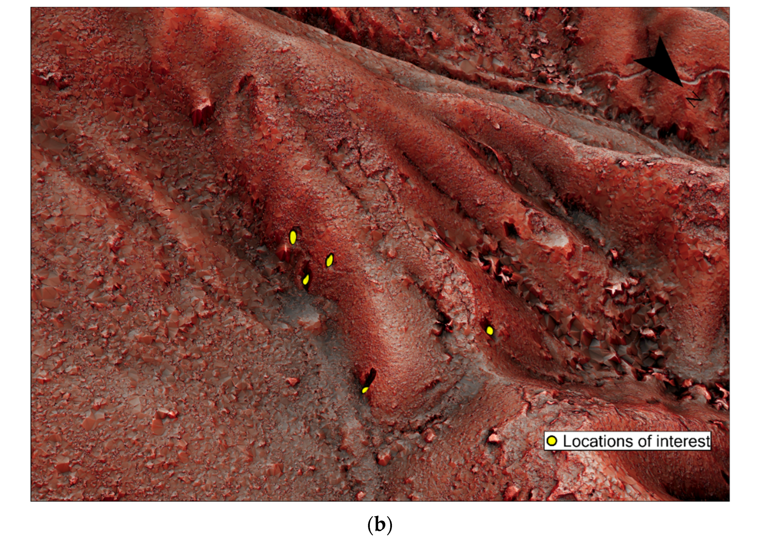
Four locations were selected to conduct field expeditions and laser scanning surveys. A DDTM-RRIM indicating the four locations is shown in Figure 2:
  • Three tunnels built by the 314th Construction Battalion in Mount Parker (Figure 3, Figure 4, Figure 5, Figure 6, Figure 7 and Figure 8);
  • Low-altitude second line of in-depth tunnel defense in Wong Nai Chung (WNC) Gap (Figure 9);
  • Pillbox, loopholes, and tunnel complex in Mount Cameron;
  • Kamikaze grotto and tunnels in Lamma Island.
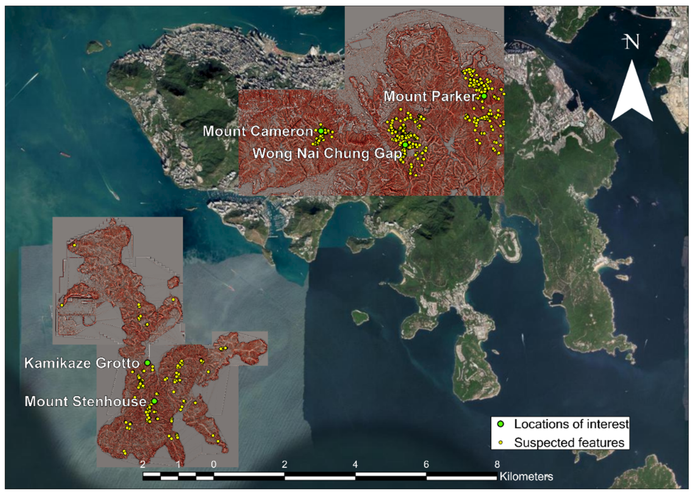
Figure 2. A DTM-RRIM showing the four locations of interest indicated by concentration of yellow dots.
Heritage 08 00294 g002
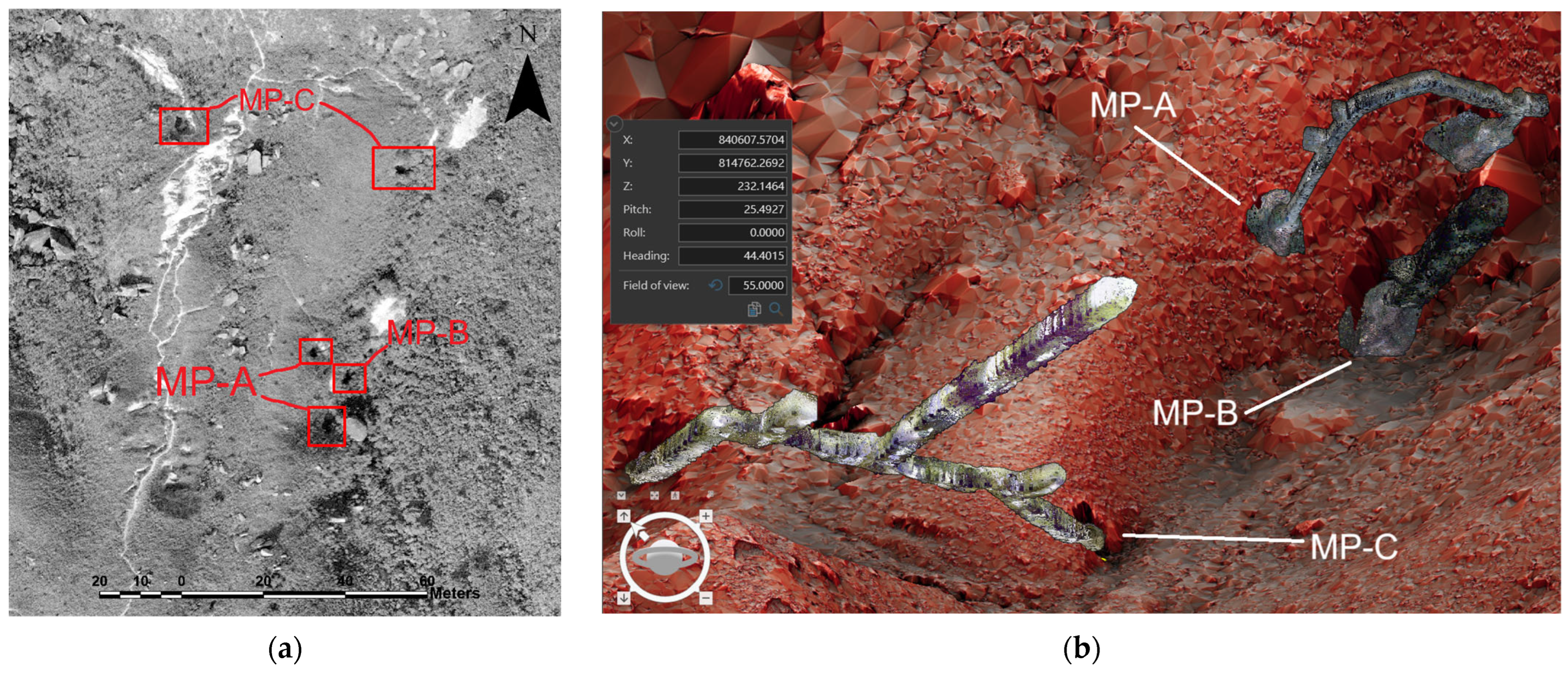
Figure 3. (a) Aerial photo of Mount Parker. (b) 3D DTM-RRIM indicating location of the three tunnels constructed by the 314th Naval Construction Battalion in Mount Parker.
Heritage 08 00294 g003
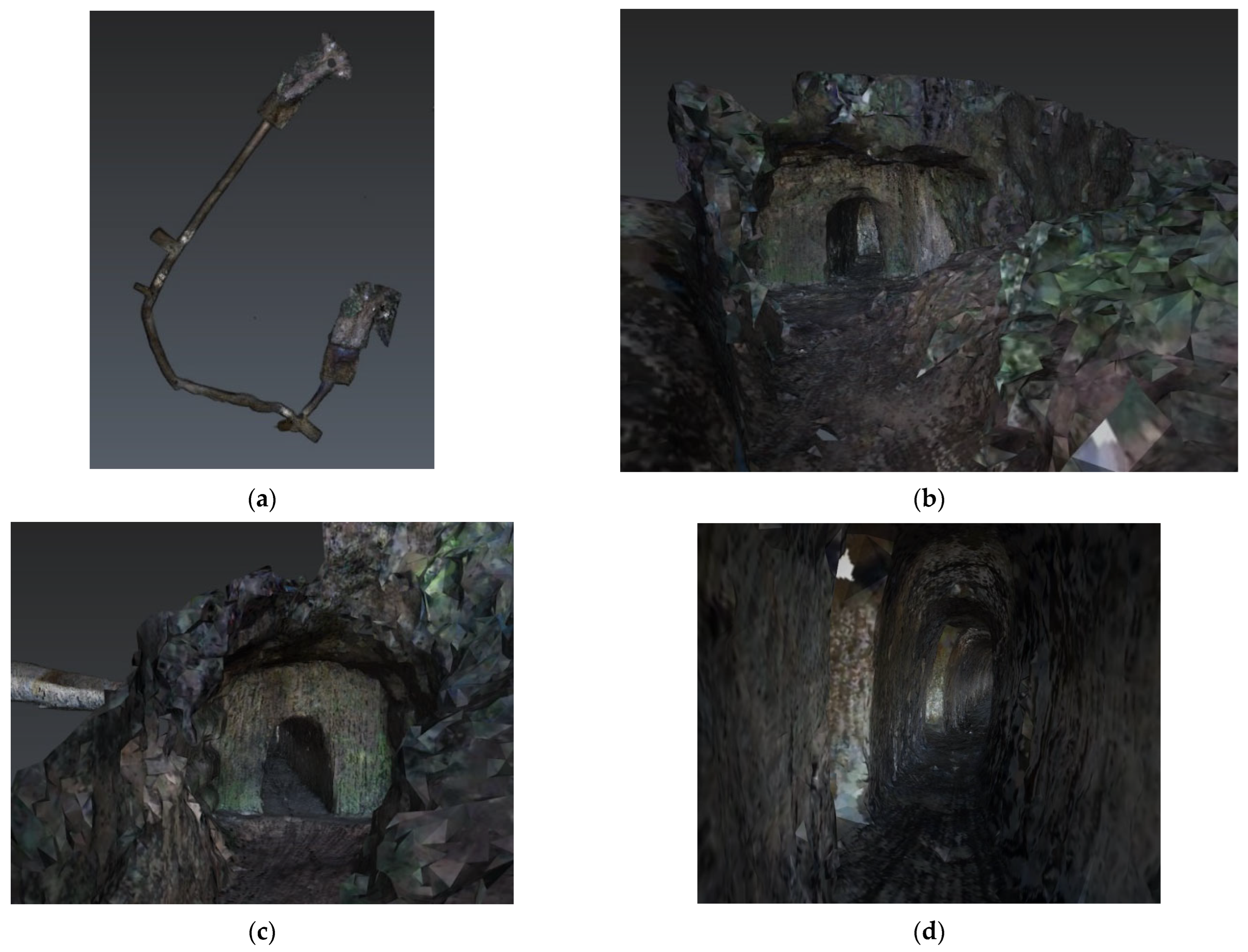
Figure 4. TLS 3D mesh model of tunnel MP-A. (a) Top view. (b,c) Front view of the tunnel entrance. (d) Inner view.
Heritage 08 00294 g004
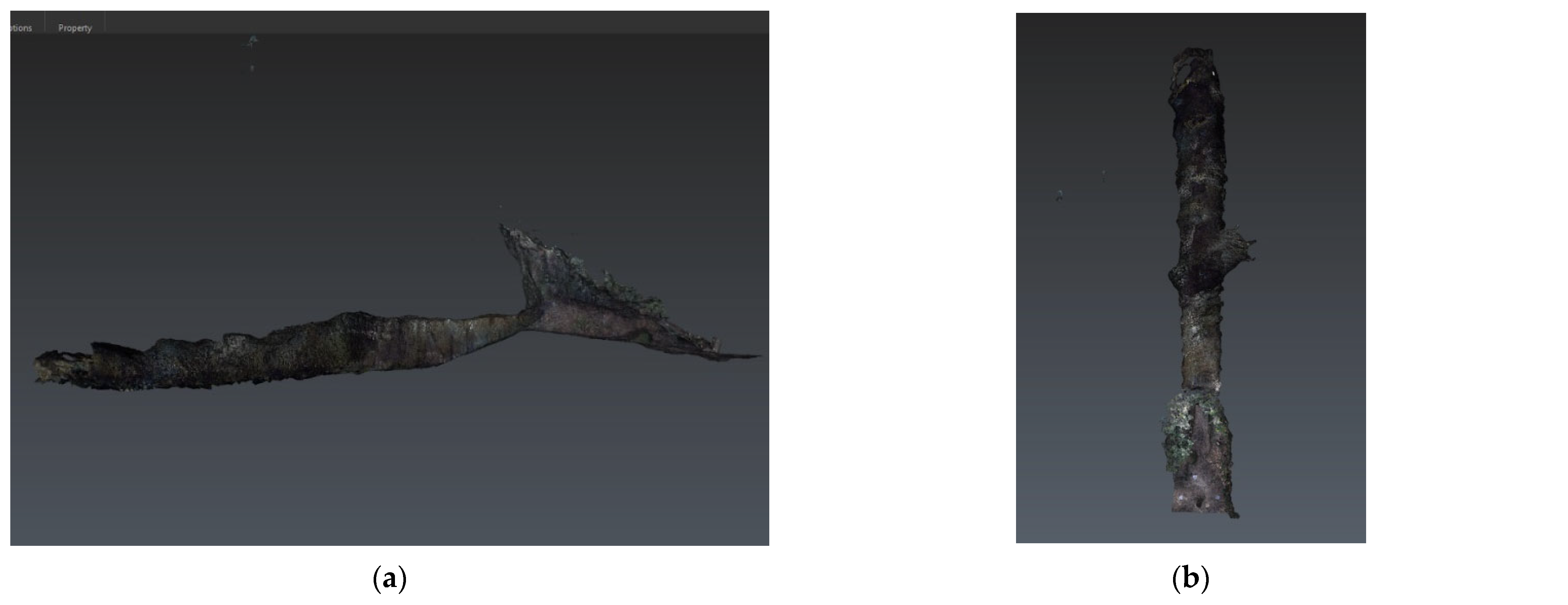
Figure 5. TLS 3D mesh Model of Tunnel MP-B. (a) Side view. (b) Top view. (c) Front view of tunnel entrance. (d) Inner view.
Heritage 08 00294 g005aHeritage 08 00294 g005b
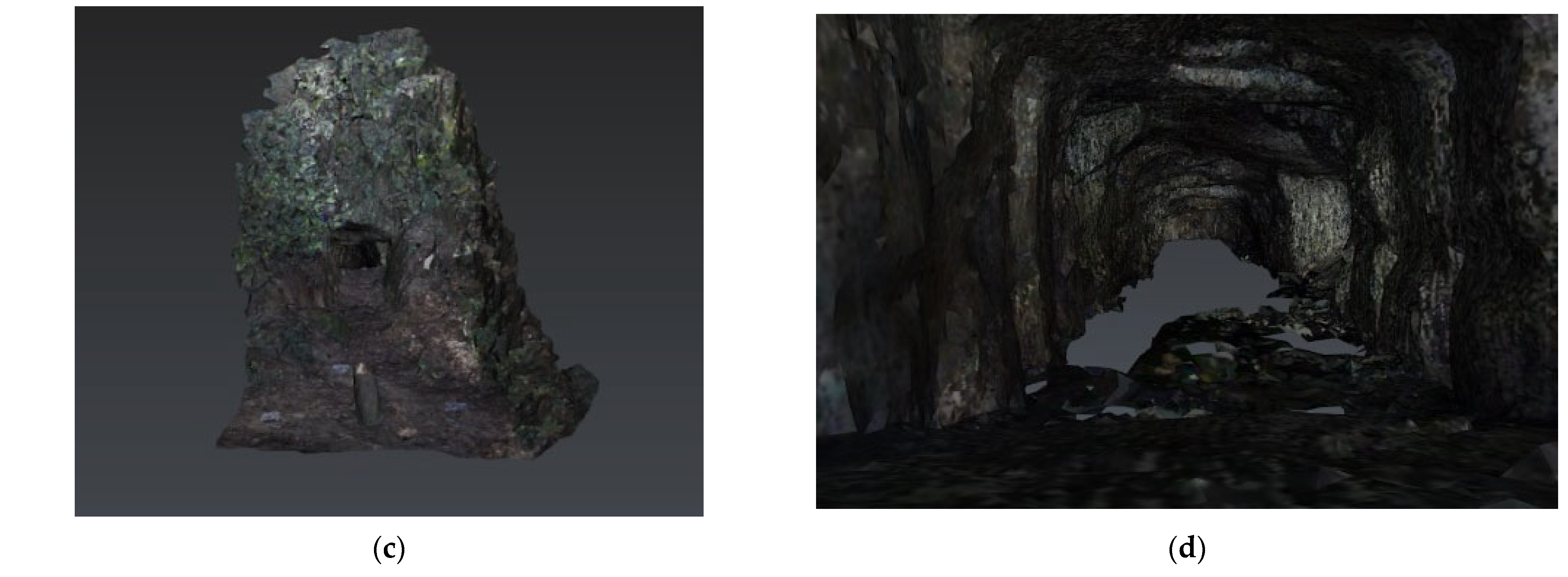
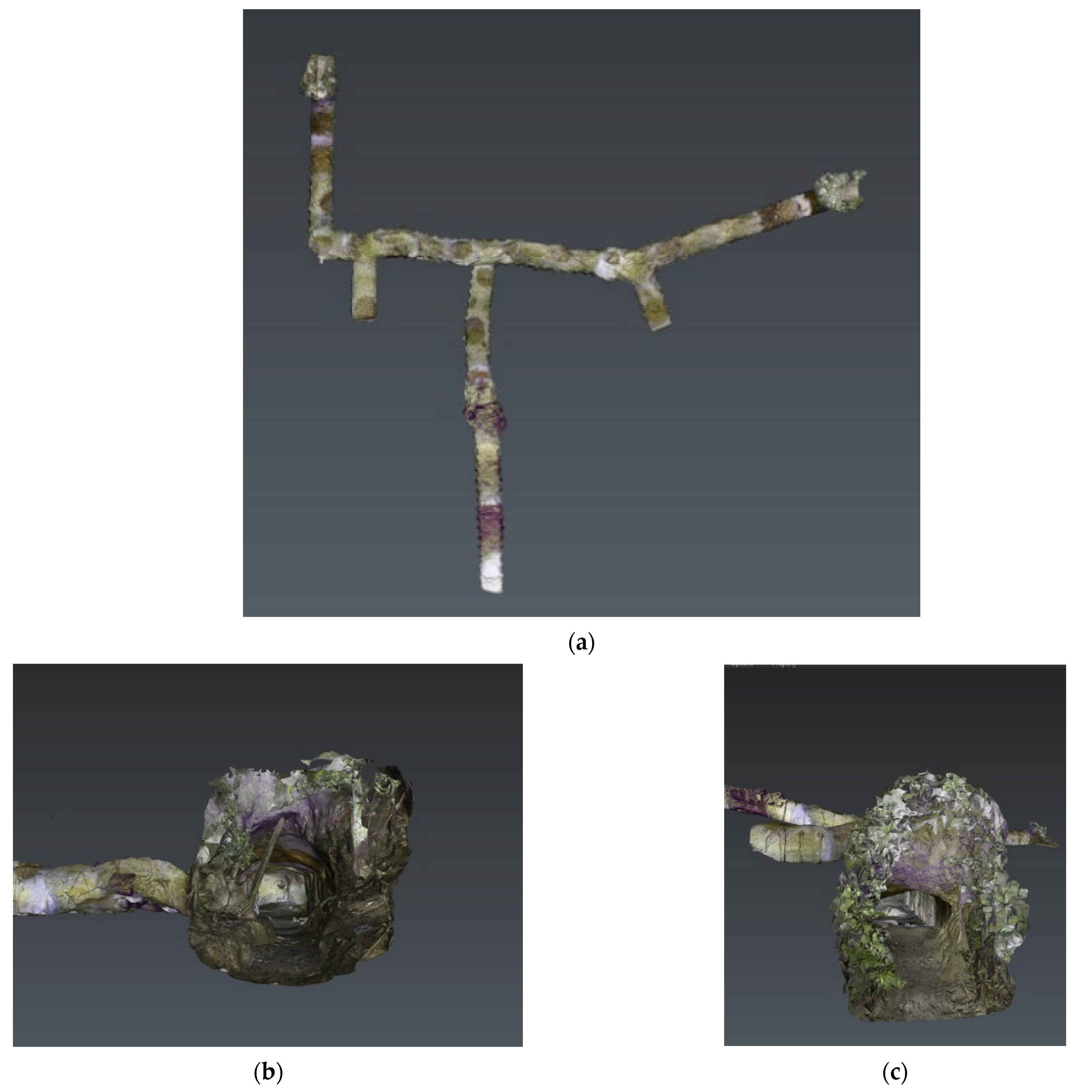
Figure 6. TLS 3D mesh model of Tunnel MP-C. (a) Top view. (b) Front view of tunnel entrance facing north. (c) Front view of tunnel entrance facing east. (d) Inner view. (e) Inner view of branch road.
Heritage 08 00294 g006aHeritage 08 00294 g006b
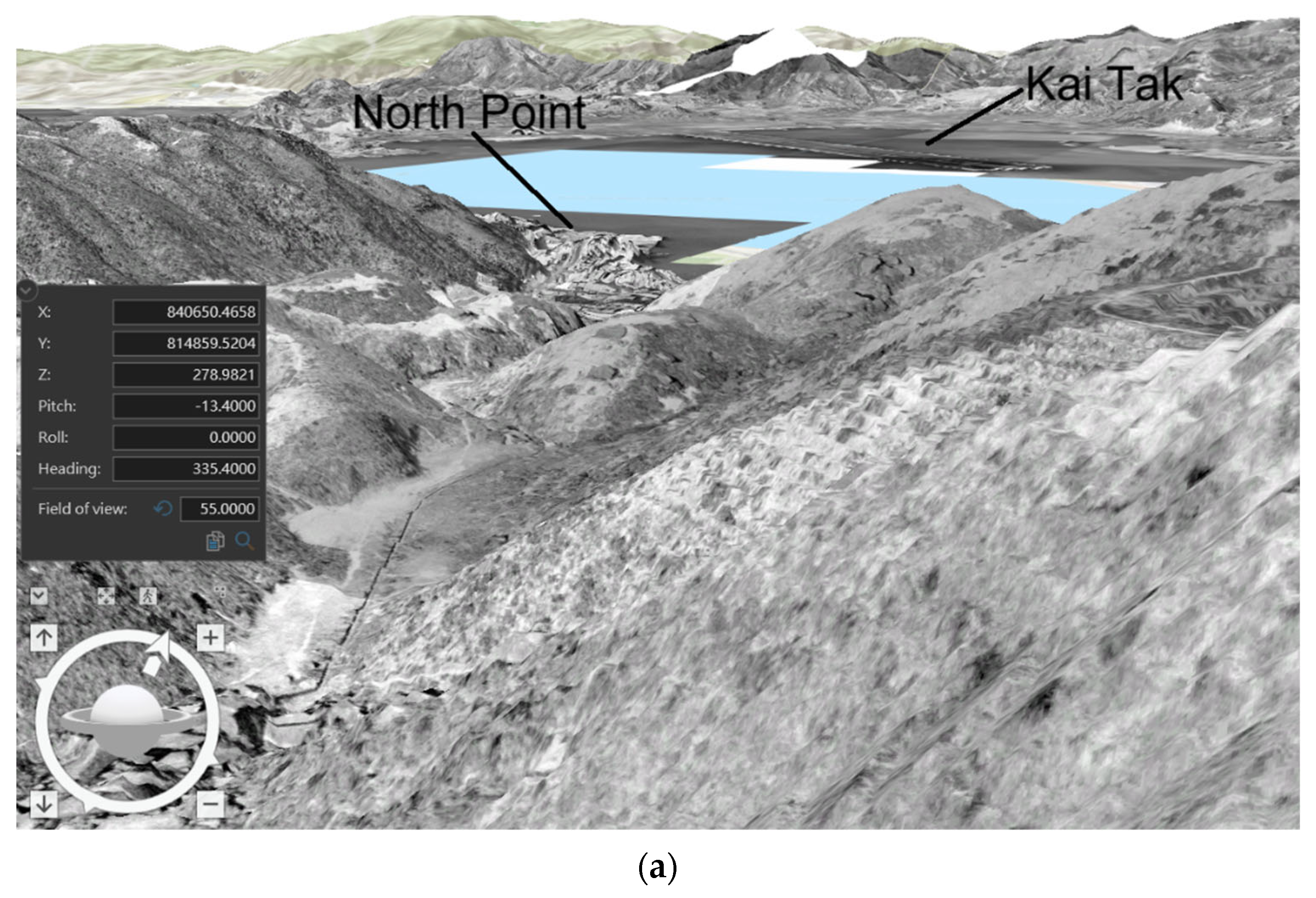
Figure 7. (a) View of the northern entrance of MP-C in 1963 DTM (b) and tunnels in Mount Parker concentrated in the same ridge.
Heritage 08 00294 g007aHeritage 08 00294 g007b
Figure 8. Suspected tunnels connecting MP-B and MP-C [5].
Heritage 08 00294 g008
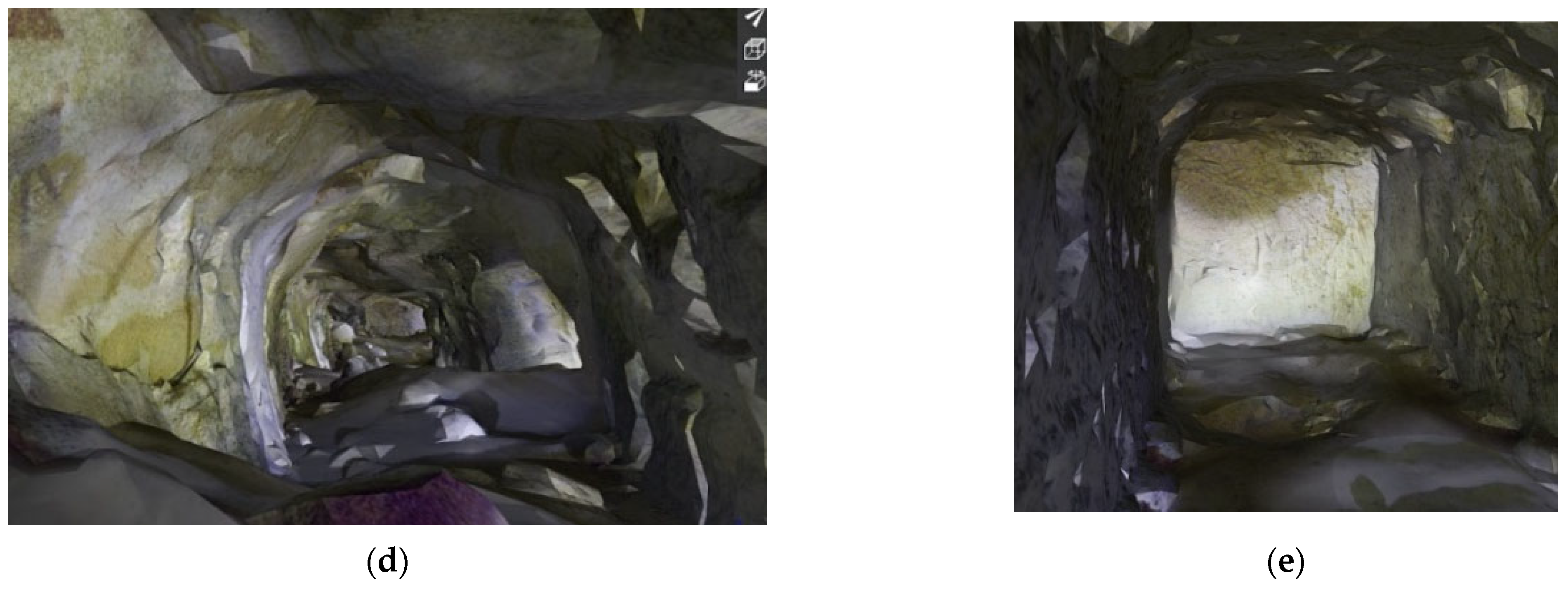
Figure 9. Discovered WNC Gap tunnel. (a) Map indicating the location of discovered tunnel. (b) Aerial photo of WNC Gap taken in 1963. (c) DTM-RRIM of the discovered tunnel. (d,e) TLS 3D mesh model of tunnel.
Heritage 08 00294 g009aHeritage 08 00294 g009bHeritage 08 00294 g009c

4.1. Mount Parker: Three Tunnels Built by the 314th Construction Battalion

During the Pacific War, the Imperial Japanese Army and Navy constructed tunnel networks as defensive positions in different parts of the Asia–Pacific region. These were extensive and complicated underground and tunnel networks developed sometimes as a huge structure with stairs and a few levels hidden under earth surface or mountains [14]. The tunnel networks were also sometimes connected with pillboxes and artillery positions. The tunnels in Mount Parker are a few features of war recorded by Japanese documents, although without mentioning their exact location. According to the war diary of the 314th Naval Construction Battalion shown in Figure 1, the battalion was ordered to construct a defensive position on Mount Parker on 1 May 1945 [3]. It remains unclear whether there were structures built in this area before this date, as the aerial photographs taken by the United States Army Air Force are not clear enough to give conclusive results. (And note) DTM-RRIM in Figure 3 indicates three distinct features corresponding to entrances/exits of three tunnels (MP-A, MP-B, and MP-C) 3D-modelled with TLS in Figure 4, Figure 5 and Figure 6, respectively. Their locations are concentrated along the same ridge, but with different sizes, directions, designs, and altitudes.

4.1.1. Geographical Characteristics

The tunnel at highest altitude (284 mPD) was a U-shaped tunnel (MP-A) with two clear-cut entrances facing north. Four junctions were found to connect four small protrusions, with around 1.5 m tall and 1 m width each. Both entrances/exits of tunnel MP-A are small but little increase in size in the inner part of tunnel. Figure 4 illustrates the TLS models scanned by Lecia RTC 360 (static laser scanner), and Table 2 reports the coordinates and its physical parameter.
The tunnel in the middle level (Tunnel MP-B) is a dead-end tunnel, with a small entrance but massive tunnel dug deep down and filled with water during our expedition. The side of the tunnel is straight; it is highly possible that the Japanese would use 8 in wood to reinforce the side of the tunnel [5]. There are protrusions on both sides of the tunnel in the same alignment. Due to the small tunnel entrance limiting the usage of the static TLS, a handheld laser scanner (Lecia BLK2GO) was used. Since the scanners emit laser, which cannot pass through water, the floor of MP-B cannot be scanned, so the bottom of the tunnel model was empty. When the end of the tunnel is reached, the water level reaches a measured height of 1.361 m from the laser scanning model; the tunnel should be around 2.5 m–2.8 m tall. Figure 5 illustrates the TLS model scanned by Lecia RTC 360 (static laser scanner), and Table 3 reports its coordinates and physical parameters.
The lowest tunnel (Tunnel MP-C) is the largest tunnel among the tunnels recorded in Mount Parker. It is an L-shaped tunnel with three dead-end branch roads facing south. Three branch roads are different in length, but designs are similar. They are suspected of being used as ammunition and depot storage. There are two entrances of the tunnel facing different directions and located on two sides of the ridge. The entrance facing north is the same size as the inner part of the tunnel, while another one facing east is much smaller. Big rubble appearing on the floor in the middle of the tunnel indicates its construction was incomplete. Figure 6 illustrates the TLS models scanned by Lecia RTC 360 (static laser scanner), and Table 4 reports its coordinates and physical parameters. This extensive tunnel entrance design is also found in a tunnel in the East New Britain Province of Papua New Guinea [15].

4.1.2. Interpretations

Three tunnels are different in size and design. MP-A is a typical Japanese infantry tunnel with few protrusions, which provide temporary shelter when the Allies shoot from outside. A Japanese tunnel in Rabaul and Kokopo, Papua New Guinea, was found that they have the same design of the clear-cut tunnel entrance as MP-A [16]. MP-B was dug downward sloping, large inside with a narrow entrance. It is likely that the tunnel was used for hiding weapons; the tunnel might be underground barracks for troops or storage, which are similar to the purpose of tunnels constructed in other Japanese-occupied area designed for storage or used as barracks. For tunnel MP-C, located at the lowest altitude but the largest tunnel among the three scanned tunnels, with 2 m height and nearly 100 m long, it is believed that the tunnel was designed as a depot for artillery.
Northern entrance of the MP-C had an excellent visibility (Figure 7a) in observing the important and strategic Northern Hong Kong Island and Kai Tak Airport, which was used as an air base by Japanese forces to support the Pacific War. We predict that the tunnel was used to accommodate Type 94 75 mm mountain gun, benefiting from its long shooting range to adequately cover the entire North Hong Kong Island and Kai Tak Airport. Not only MP-C, but all scanned tunnel entrances are facing northeast Lei Yue Mun and Yau Tong, the eastern entrance of Victoria Harbour, and the strategic Devil Peak batteries at Kowloon. These two military positions are only around 2–4 km from these three tunnels, meaning they are under the perfect fire ranging zone of most mountain guns and mortars defending the east of Victoria Harbour against the invasion of Allied forces.
However, we believe that these tunnel networks, though constructed on the same ridge and close to each other as shown in Figure 7b, were not completed when the Japanese declared unconditional surrender in August 1945. The protrusions in MP-B provide evidence in Figure 8, where orientations of the incomplete tunnels MP-B and MP-C were geographically connected when the 3D TLS models are overlaid on DTM-RRIM. If the protrusion of MP-B would have been further dug, it should be able to connect to one of the branch roads in MP-C. This finding was only made clear in Figure 8 with the combination of geospatial technologies adopted.

4.2. Wong Nai Chung (WNC) Gap: A Low-Altitude Second Line of In-Depth Tunnel Defense

During the Japanese invasion of Hong Kong in December 1941, the Japanese forces landed on the northeastern shore of Hong Kong Island on the evening of 18 December and then pushed into WNC Gap, where heavy fighting ensued, leaving hundreds of casualties on both sides (footnote). Then in 1944, when the American invasion was becoming imminent, it is believed that the Japanese built additional defensive positions in the vicinity of WNC Gap, where these traces of war were hidden in the thick vegetation today.

4.2.1. Geographical Characteristics

The 1963 aerial photo (Figure 9b) and the 2020 DTM-RRIM (Figure 9c) reveal some unnatural terrain features above Tai Tam Barbecue Site Area Site 1. These features were very likely constructed by the Japanese occupation force at locations near the occupied British pillboxes and lines of defense because some similar features appear in Devil Peak and Braemar Hill. A tunnel mapped in Figure 9a is discovered in desktop study and confirmed in field expedition. Unlike the three Mount Parker tunnels, the newly discovered tunnel is neither mentioned in the war diary of 314 Construction Battalion nor other sources. The tunnel is a straight and dead-end one without any room or intrusion and no obvious variation in size. Handheld laser scanner (Lecia BLK2GO) was employed to complete the scanning due to its small size. Figure 9d,e illustrates the TLS model, and Table 5 lists the physical parameters of the tunnel.
The plan of tunnel construction is predicted to be similar to the suspected connection between MP-B and MP-C in Mount Parker, that the tunnel network in WNC Gap was also suspected but not completed before the war was over. The DTM-RRIM can prove this hypothesis, after combining the DTM-RRIM and the 3D laser scanning model of the 14 m long tunnel. Figure 9c shows that there was a small unnatural platform (yellow dot appears in the figure) located on the other side of the ridge, and it is only 55 m away from the tunnels. The size and orientation of the tunnel pretty much match the platform. It is highly possible that the platform is the other end of the scanned tunnel, but the construction is incomplete.

4.2.2. Interpretation

Unlike MP-A, -B, and -C in Mount Parker, the WNC Gap war tunnel is not located in an advantageous position because the angle of view is too narrow, which could not target to any strategic direction as the tunnel in Mount Parker, nor built for observation purpose. The tunnels may be constructed as the second line of in-depth defense or depot for ammunition, expecting a fighting retreat from the first line of defense on the coast. Like the defense plan in Iwo Jima, they expected the U.S. forces to land on the south of Iwo Jima; hence, their defense lines were designed to span from the south and mostly focus their defense line on the north of Iwo Jima. Geospatial technologies enable to establish this connection at these two places.

4.3. Mount Cameron: Possible Infantry Position

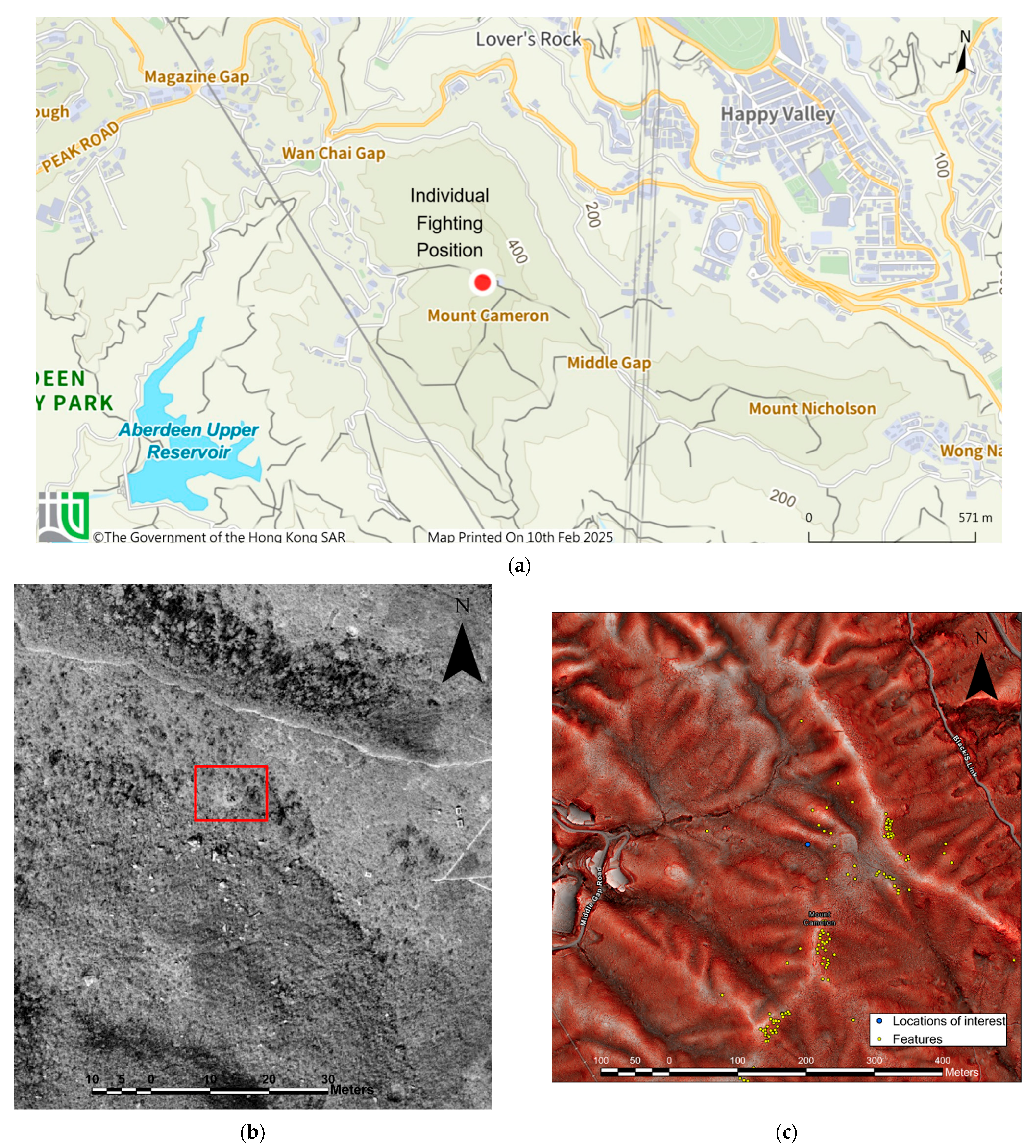
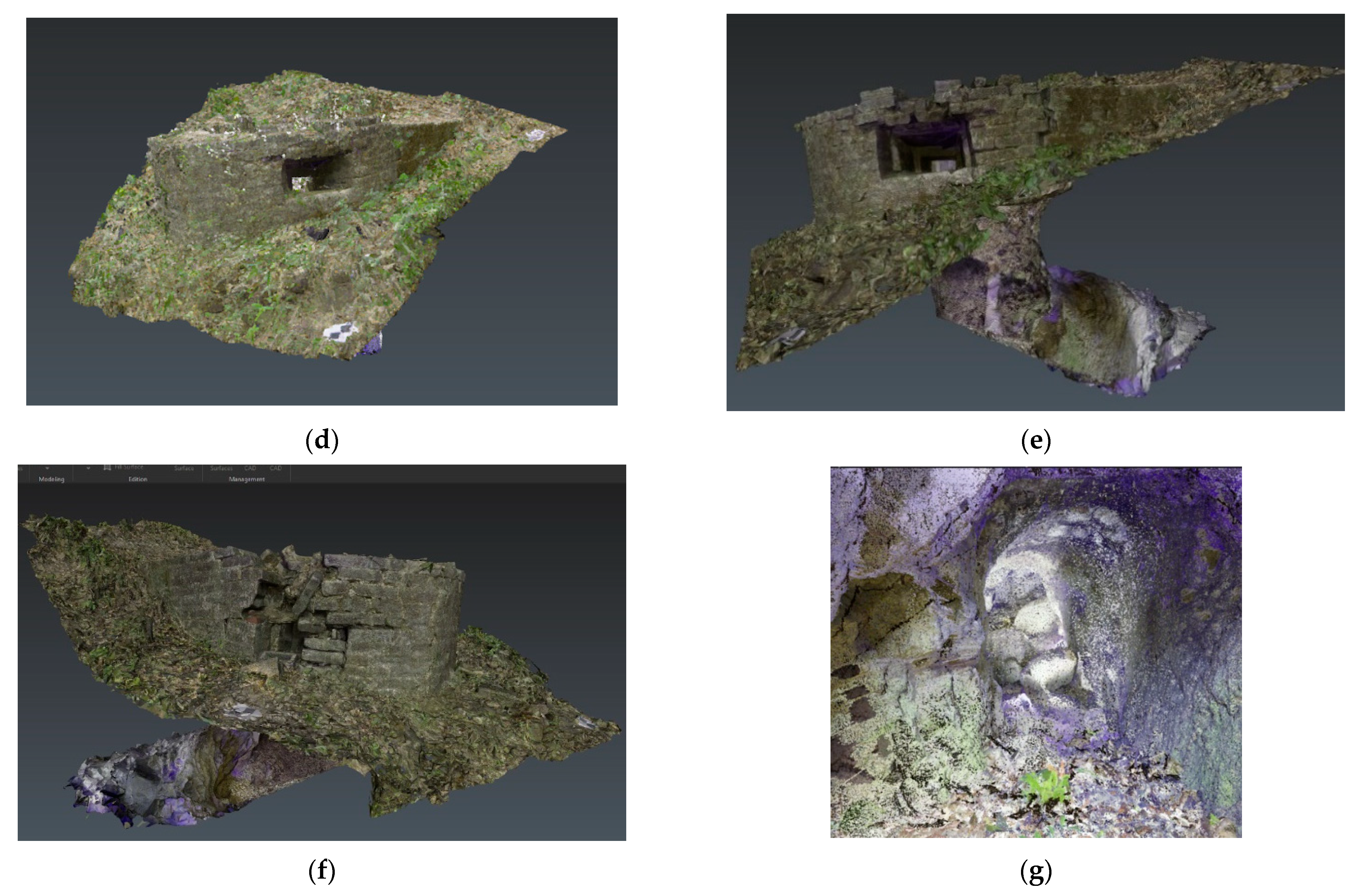
The possible infantry position located in Mount Cameron (Figure 10a) was first discovered in 2013 and posted on Gwulo [17], a webpage set up by local historian David Bellis that attracted the contribution of numerous history enthusiasts. The position consisted of a parapet and a tunnel complex. The design of the structure was U-shaped, a parapet-like structure constructed by bricks without a ceiling and with two loopholes and a dead-end tunnel underneath. This military structure design is rarely found in Hong Kong, and whether it was actually a military structure remains unknown.

4.3.1. Geographical Characteristics

The aerial photo taken in 1963 (Figure 10b) shows the structure already existed by then. During the Battle of Hong Kong, the area was occupied by the 228th Infantry Regiment [18], as it is war history recorded. During the site visit, we found a few scattered foxholes on the hillside, and their locations approximately match the field position marked on this 228th Infantry Regiment record. Figure 10 shows the scanned models of the structure scanned by Lecia RTC 360 (static laser scanner), and Table 6 reports the physical parameters and coordinates of the position.

4.3.2. Interpretations

The parapet-like structure with two loopholes, connected with a 7 m long tunnel underneath, might be used for storing small-sized weapons and bullets to support the frontline operation. By its size of the structure and other reference [19], it is suspected that the structure is an individual fighting position for one or two soldiers to stay, as the appearance of loopholes means that it was designed to use for shooting, and the location of the structure in Mount Cameron has a great advantage in observing the Aberdeen reservoir, fresh water supply for southern part of Hong Kong Island, which is just 1–1.5 km away from the position under an effective shooting range. It is also possible that the structure was planned to connect to other tunnel networks in Mount Cameron, which failed to finish construction work before the war ended. There is a nearby incomplete tunnel network that was verified during site visits.

4.4. Lamma Island: Suicidal Kamikaze Grotto and Tunnel

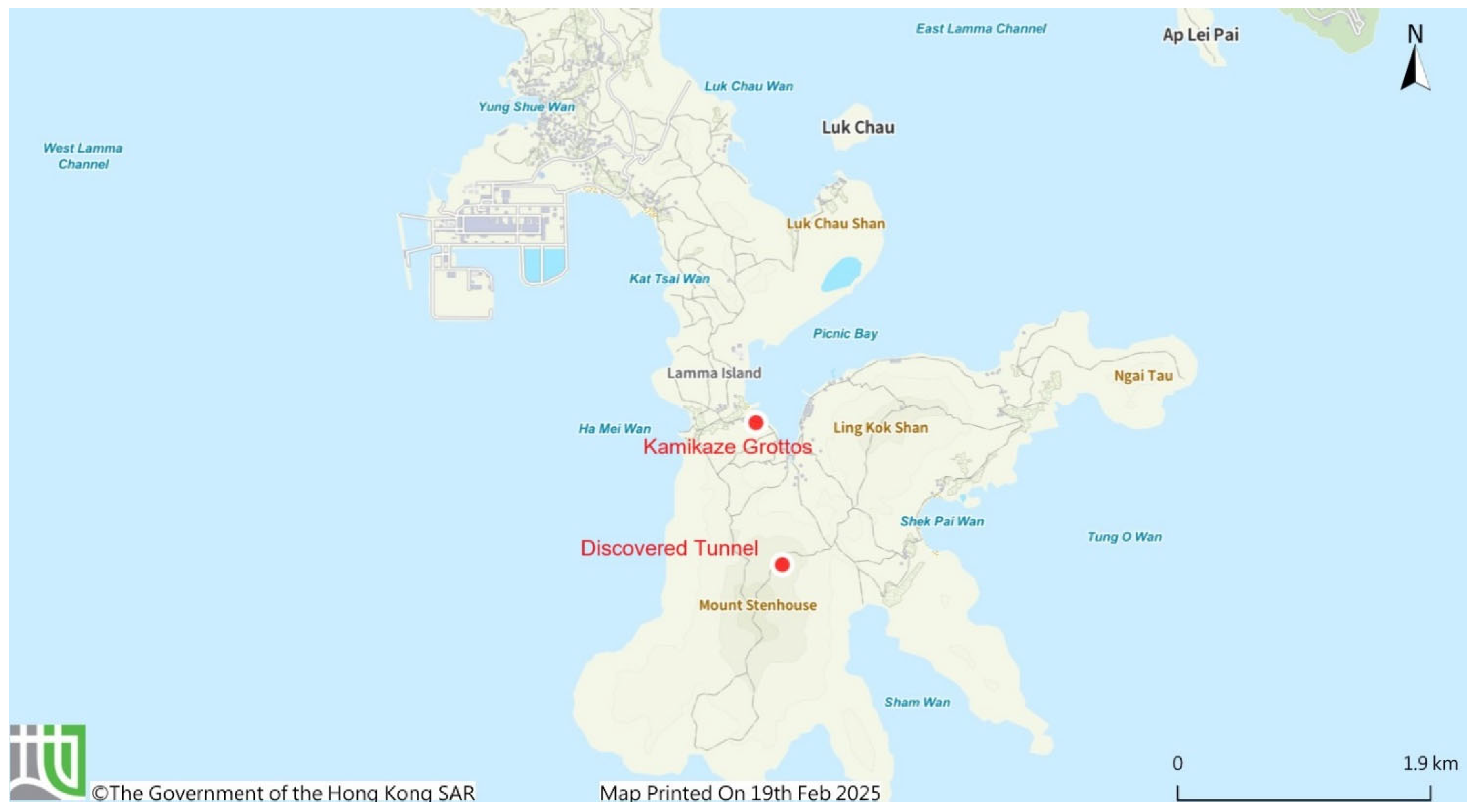
The war diary of the 314th Naval Construction Battalion also mentioned the construction of features on Lamma Island. This text-based diary described the construction of tunnels, batteries, and other structures, but exact locations were not recorded [3]. Cross-referencing this diary, aerial photos, DTM-RRIM, and memories of locals on Lamma Island, some of these features of war could be predicted. According to the locals and hikers’ witnesses, Japanese Navy constructed batteries and a couple of tunnels on the hills on Lamma Island. The DTM-RRIM reveals hundreds of unnatural features on hills among Lamma Island. During the expedition, we have found a couple gun positions and tunnels, and a Kamikaze grotto and one tunnel in Mount Stenhouse are chosen to conduct the 3D TLS model in this study (Figure 11).

4.4.1. Geographical Characteristics

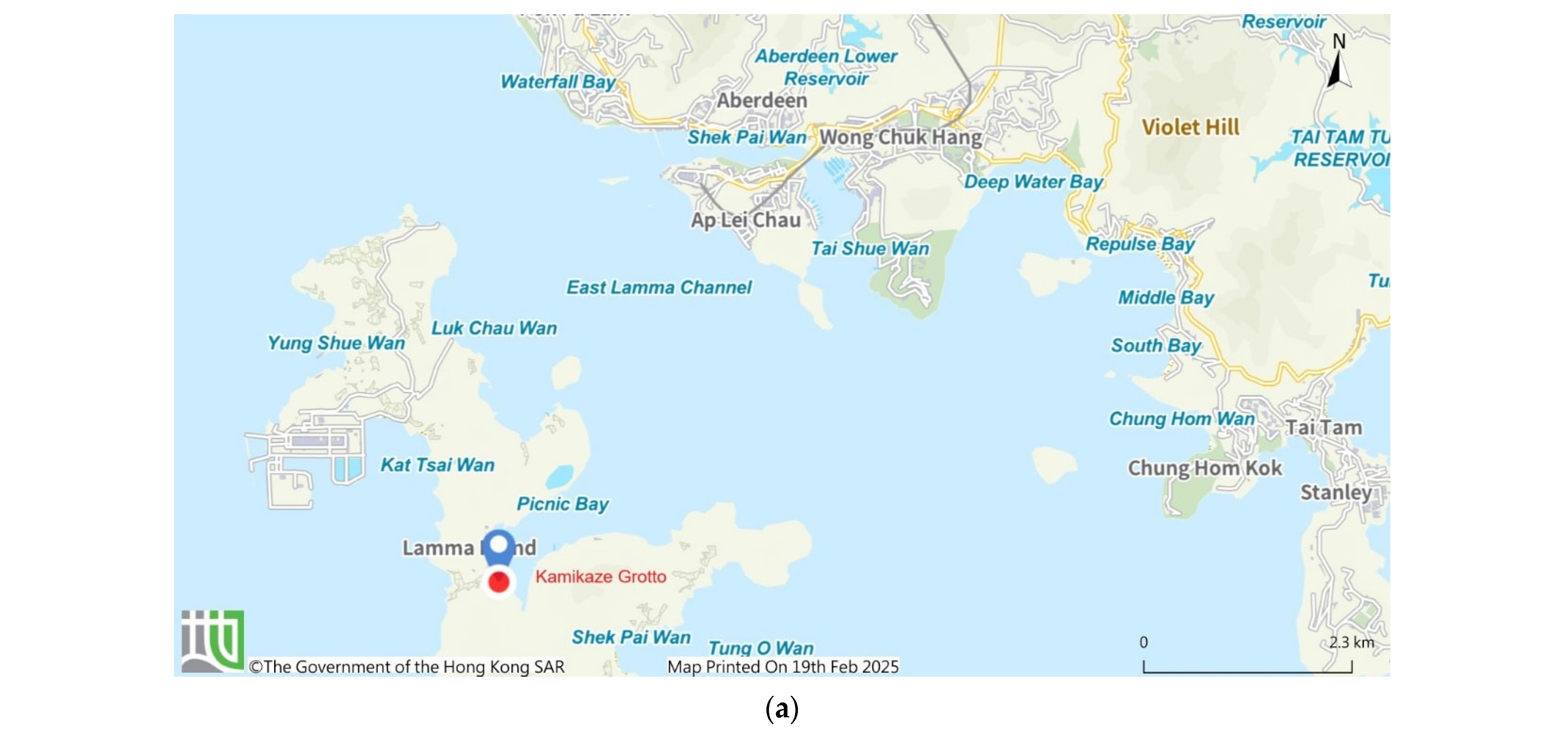
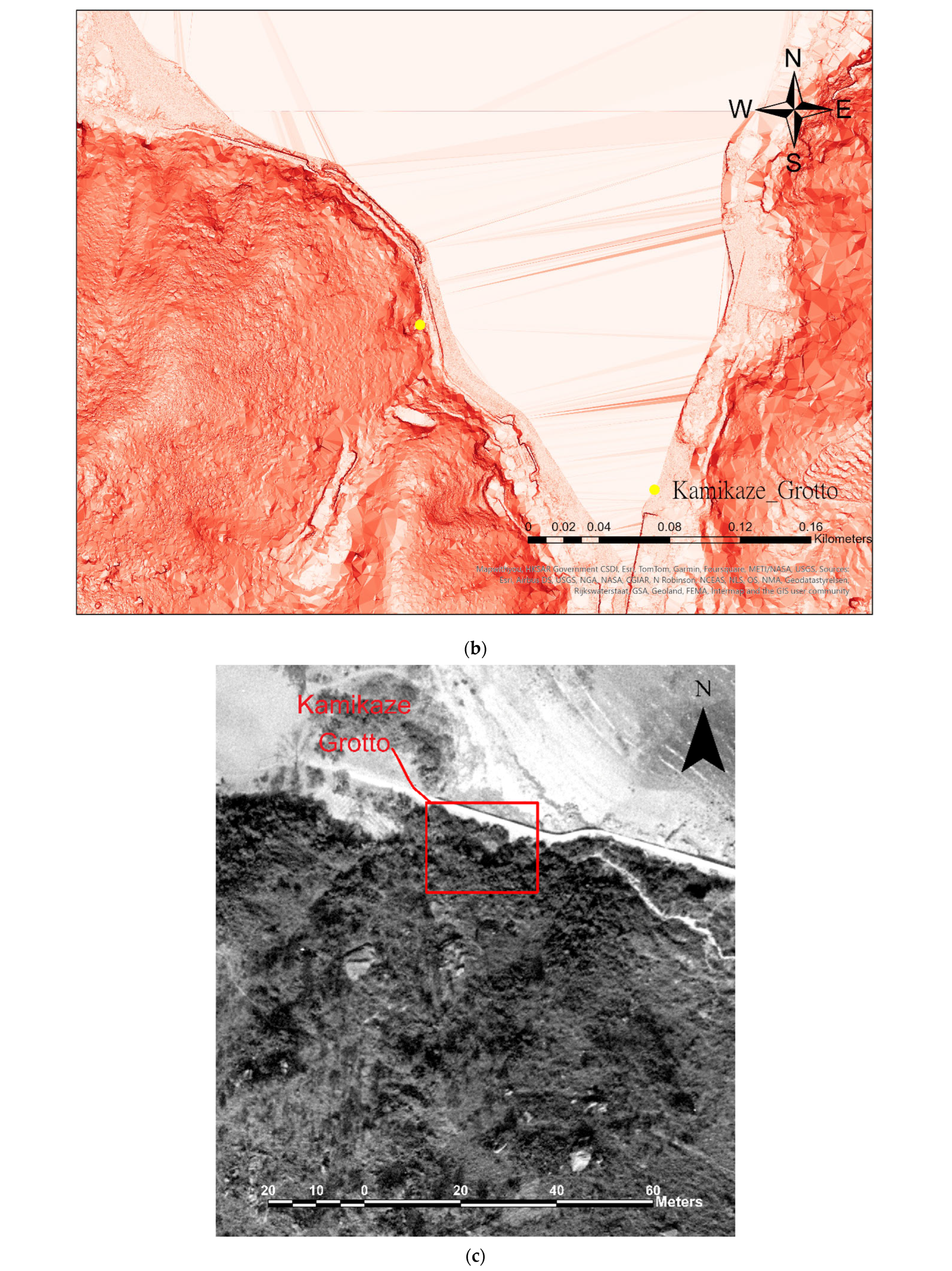
Kamikaze grottos are caves dug by Japanese Navy along the coast of Sok Kwu Wan (also named as Picnic Bay). The Japanese Navy would use “Shinyo” suicidal boats against an Allied invasion fleet, had it approached Hong Kong [20]. However, the war ended before this tactic was implemented, as the Allied forces had not invaded Hong Kong. The scanned Kamikaze grotto is located along the coast, but nowadays, a new pathway was built in between after the war ended. The grotto is a dead-end and straightforward cave without any protrusions or paths to connect. It is 28.4 m in length, 3.6 m in width × 2.2 m high. Figure 12 shows the TLS 3D model of the grotto scanned by Lecia RTC 360 (static laser scanner), and Table 7 reports the statistics of the grotto. The grotto is facing Sok Kwu Wan, a bay shown in Figure 12a, located at the southeast part of Lamma Island, which can easily access East Lamma Channel, a strait connecting South China Sea and Victoria Harbour. With deployment of Kamikaze Grotto in Sok Kwu Wan, it would threaten the Allied forces reaching Hong Kong by forming a crossfire network.
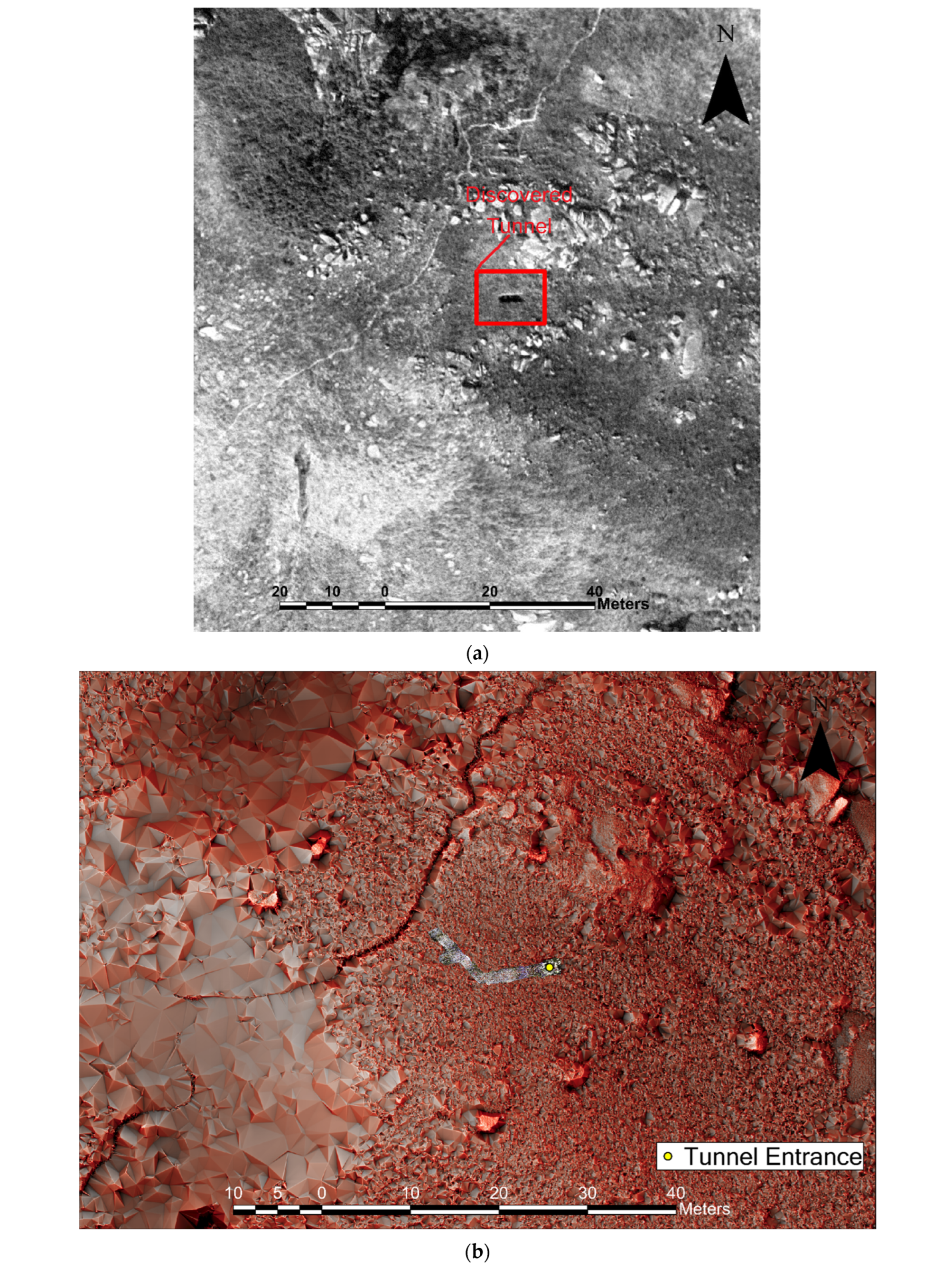
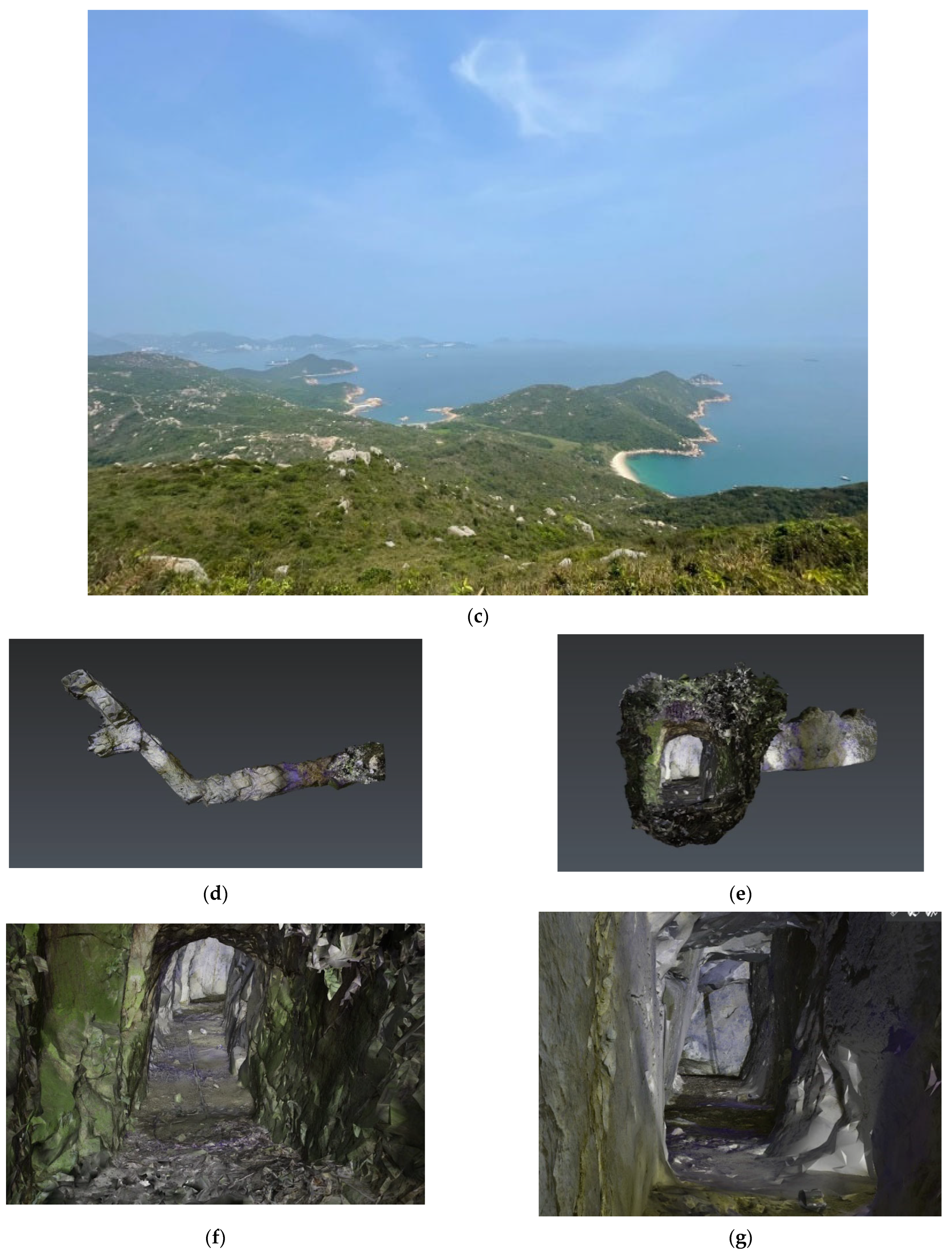
The newly discovered tunnel in this study is in Mount Stenhouse, southwest part of Lamma Island. According to the witness record of the locals and different sources [21], the Japanese Navy constructed lots of fortifications and features of war on Mount Stenhouse [22]. In fact, many suspicious spots were pinpointed in research stage, but only a few of them were able to be verified in the site visit due to heavy vegetation. The scanned tunnel is one of the accessible tunnels with no evidence of human activities or records after the war. In this tunnel, there is no secondary exit, and the only access is located on the steep slope of the northeast part of Mount Stenhouse. The tunnel is straightforward for a few meters. Then turn right for 40 degrees, where two small protrusions appear on the left side of the tunnel after the right turn, and the tunnel then comes to an end. Figure 13 shows the 3D model of the grotto scanned by Lecia RTC 360 (static laser scanner), and Table 8 reports the physical parameters and coordinates of the tunnel.

4.4.2. Interpretation

The tunnel in Mount Stenhouse is located at a great advantage in terrain, no matter in terms of the angle of view or its secret location. Similar to those that were found in Iwo Jima, it is in hilly relief where enemies are difficult to approach. The angle view is widely facing the east and south part of Lamma Island; the tunnel can observe the East Lamma Channel clearly. Figure 13c shows that the tunnel is a good and strategic observation spot that can monitor any vessel movement in the East Lamma Channel. Furthermore, the channel is 3–5 km away from the tunnel, which is well within the range of Type 94 mountain gun, a common mountain gun deployed by Japanese forces during WWII. The tunnel can effectively protect the channel with small number of guns.
Besides, according to the war diary by the 314th Naval Construction Battalion, the Japanese force planned to construct multiple positions on Lamma Island, and witnesses stated that fortifications were constructed at Mount Stenhouse [21]. Our desktop study and site visit can support this statement. It is possible that the Japanese might plan to construct a tunnel network on Mount Stenhouse to link all the tunnels and gun positions, turning into a massive fortification, like structures constructed in Iwo Jima and Okinawa, but were never able to finish. A more detailed study shall be conducted.

5. Japanese Defense Tactics Revealed by Geospatial Technologies

From ancient warfare to the First World War and the present Israel–Hamas War, tunnels played an important role in land warfare. During the latter stage of the Pacific War, Japanese forces constructed countless fortifications in areas under their control. As the Allied forces had established control over the skies and then the seas during the latter part of the war, they were able to deliver heavy firepower on any Japanese defenses. Lacking countermeasures, the Japanese forces used natural landscape with tunnels and caves to mitigate the Allied advantage in firepower; in some cases, the Japanese forces were able to substantially extend the duration of resistance, especially when the garrison did not engage in futile mass counterattacks [14]. The Battle of Iwo Jima in March 1945 was a case in point.
In our investigation with geospatial technologies in Hong Kong, military tunnels were constructed by the Japanese Army and Navy, by units such as the 314th Naval Construction Battalion, on Mount Parker, Mount Camreon, WNC Gap, and Lamma Island. They are far smaller in size than those in Iwo Jima, but the intentions and the functions are similar. According to Kwong [23,24], there were only around 4000 soldiers to defend Hong Kong toward the end of the war. With such a small garrison, the Japanese relied on terrain, and fortifications narrowed the huge gap in military power. Many of these works remained unfinished when the war ended in August 1945. Table 9 compares the Japanese tunnels discovered in Hong Kong and other Japanese-occupied area.
With geospatial technologies, we can have a more in-depth discussion of these Japanese-built features, despite the fact that documentary sources are limited. It is observed that the Japanese adopted tactics that relied on terrain and concealment, similar to the one that was adopted by the Japanese garrison in Iwo Jima and Okinawa. Whether the Japanese forces in Hong Kong were able to mount a (relatively) successful defensive battle remained uncertain; however, the quality of the Japanese garrison force in Hong Kong was very different from those that garrisoned Iwo Jima, Okinawa, or other Pacific Islands such as Saipan.
But more unknowns are yet to be found and discovered:
  • Can we substantially reconstruct the Japanese defensive positions in DTM-RRIM, if not to the full extent? Can the dots be connected from point to line and from line to plane through geospatial technologies?
  • Can the suspicious features of war be categorized into their functions, like observation posts, anti-aircraft positions, artillery, or infantry units? Can we identify their different builders through such categorization?
  • WNC Gap: The possible entrance of the tunnel discovered was reported, but more suspicious features of war with DTM-RRIM were identified and are yet to be confirmed.
  • Lamma Island: Japanese Navy dedicated to build a military base according to the 314th Battalion war diary, especially the four concrete batteries and associated structures. Where are they? Were they remaining hidden or demolished after the war?

6. Conclusions

It is fortunate that Hong Kong was spared from another counterinvasion by the Allied forces during the Japanese occupation; had it occurred, it would have brought extensive destruction to the city. The remaining Japanese military structures in Hong Kong was the testament of a brutal battle that did not occur, and we are able to know more about these structures through a systematic and tech-based approach. The workflow outlined in this paper enables us to look from above and on the ground to assess the defensive structures and tactics of the Japanese garrison, even when written records are limited. But more understandings also bring more questions, such as the four questions raised in Section 5. Also, after all these discoveries and recordings of these features, what should be the next step? In what ways can the public be involved to understand this part of history and heritage? How shall these features of war be preserved and presented? It is clear that more public engagement activities are needed, which rest on the open-minded cooperation with various stakeholders ranging from educational institutions, professionals, educated enthusiasts, and the general public.

Author Contributions

Conceptualization, W.-W.-L.L. and C.-M.K.; methodology, W.-W.-L.L. and C.-M.K.; software, C.-H.L. and C.-H.P.; validation, C.-H.L., C.-H.P. and C.M.; formal analysis, C.-H.L. and C.-H.P.; investigation, W.-W.-L.L., C.-M.K., C.-H.L., C.-H.P. and C.M.; resources, W.-W.-L.L. and C.-M.K.; data curation, C.-H.L. and C.-H.P.; writing—C.-H.L., W.-W.-L.L. and C.-M.K.; writing—review and editing, W.-W.-L.L. and C.-M.K.; visualization, C.-H.L. and C.-H.P.; supervision, W.-W.-L.L.; project administration, W.-W.-L.L.; funding acquisition, W.-W.-L.L. All authors have read and agreed to the published version of the manuscript.

Funding

This research was funded by [Research Institute of Land and Space of The Hong Kong Polytechnic University] at a project titled ‘Characterizing Wartime Archaeology and Heritages by LiDAR-Digital Elevation Models’ with grant number [P0045877].

Data Availability Statement

For airborne LiDAR data, the data presented in this study are available in [Civil Engineering Development Department of HKSAR Government]. These data were derived from the following resources available in the public domain: [https://www.ginfo.cedd.gov.hk/geoopendata/eng/LIDAR.aspx, accessed on 11 July 2025]. For laser scanning data, the raw data supporting the conclusions of this article will be made available by the authors on request.

Conflicts of Interest

The authors declare no conflict of interest.

References

  1. Sit, K.F.-C.; Pun, C.-H.; Lai, W.W.L.; Chung, D.K.-W.; Kwong, C.-M. Unfolding WWII Heritages with Airborne and Ground-Based Laser Scanning. Heritage 2023, 6, 6189–6212. Available online: https://www.mdpi.com/2571-9408/6/9/325 (accessed on 11 July 2025). [CrossRef]
  2. Isogai, R. 磯谷總督參考綴 [Isogai Shiryo Sotoku Sankotetsu]; Leung, K.L., Ed.; Hong Kong Museum of History Collection: Hong Kong, China, 1945; p. 112. [Google Scholar]
  3. Wartime Diary From April 1 to June 30, 1945, 314th Construction Battalion (6); REF.C08030298900; Japan Center for Asian Historical Record (JACAR): Tokyo, Japan, 1945.
  4. Hong Kong Baptist University Library. The Battle of Hong Kong 1941: A Spatial History Project. 2021. Available online: http://digital.lib.hkbu.edu.hk/history/ (accessed on 11 April 2024).
  5. LSGI, The Hong Kong Polytecnic University, Unfolding the lost WWII Heritage: A New Chapter of Geo-Spatial and Geophysical Technologies in HK, 25 June 2024. [Video File]. Available online: https://youtu.be/wuUfqo5NQC0?si=F5R0aMJpGyGOOU8h (accessed on 24 January 2025).
  6. Chase, A.F.; Chase, D.Z.; Weishampel, J.F.; Drake, J.B.; Shrestha, R.L.; Slatton, K.C.; Awe, J.J.; Carter, W.E. Airborne LiDAR, archaeology, and the ancient Maya landscape at Caracol, Belize. J. Archaeol. Sci. 2011, 38, 387–398. [Google Scholar] [CrossRef]
  7. Johnson, K.M.; Ouimet, W.B. Rediscovering the lost archaeological landscape of southern New England using airborne light detection and ranging (LiDAR). J. Archaeol. Sci. 2014, 43, 9–20. [Google Scholar] [CrossRef]
  8. Shimoda, I.; Tsuyoshi, H.; Chiba, T.; Shimoda, M. The Advanced Hydraulic City Structure of the Royal City of Angkor Thom and Vicinity Revealed through a High-Resolution Red Relief Image Map. Archaeol. Discov. 2016, 4, 22–36. [Google Scholar] [CrossRef]
  9. Asia Air Survey Co., Ltd. Red Relief Image Map, ca. 2017. Available online: https://www.rrim.jp/en/ (accessed on 21 February 2025).
  10. OpenTopography. What Is Lidar? 2015. Available online: https://opentopography.org/lidar_basics (accessed on 15 April 2024).
  11. Geodetic Survey Section, Survey and Mapping Office, Lands Department, Welcome to Hong Kong Satellite Positioning Reference Station Network (SatRef). 2024. Available online: https://www.geodetic.gov.hk/en/satref/satref.htm (accessed on 20 December 2024).
  12. Ebrahim, M.A.-B. 3D laser scanners’ techniques overview. Int. J. Sci. Res. 2015, 4, 323–331. [Google Scholar]
  13. Pritchard, D.; Sperner, J.; Hoepner, S.; Tenschert, R. Terrestrial laser scanning for heritage conservation: The Cologne Cathedral documentation project. ISPRS Ann. Photogramm. Remote Sens. Spat. Inf. Sci. 2017, IV-2/W2, 213–220. [Google Scholar] [CrossRef]
  14. Hanesalo, B.A. Asian Tunnel Warfare: A Collection of Documents Detailing Asian Tunnel Warfare Techniques; Military/Info: Minneapolis, MN, USA, 1996. [Google Scholar]
  15. PapuaNiugini.org, Japanese Tunnels in WW2 in the East New Britain Province of Papua New Guinea. 2022. Available online: https://papuaniugini.org/japanese-tunnels-in-ww2-in-the-east-new-britain-province-of-papua-new-guinea/?amp=1 (accessed on 22 January 2025).
  16. No Leg Room, Force. 2023. Available online: https://nolegroom.ca/2023/07/31/force/ (accessed on 22 January 2025).
  17. Mitchell, C. Japanese Pillbox/Tunnel on Mt. Cameron [????- ]. 12 April 2013. [Online Forum]. Available online: https://gwulo.com/node/18129#16~22.2647~114.1725~Map_by_GovHK-Markers~100 (accessed on 17 February 2025).
  18. Anon. Hohei dai ninihachi rentai shi [History of the 228th Infantry Regiment]; Hohei dai ninihachi rentai shi kankōkai: Nagoya, Japan, 1973; p. 92. [Google Scholar]
  19. Rogers, J.D. Japanese Defenses and Fortifications Taeawa, Iwo Jima and Okinawa. 1943–1945. Available online: https://web.mst.edu/rogersda/umrcourses/ge342/Japanese%20Island%20Defenses%201943-45.pdf (accessed on 11 July 2025).
  20. Home Affairs Department. Kamikaze Cave. 2022. Available online: https://www.gohk.gov.hk/en/spots/spot_detail.php?spot=Kamikaze+Cave (accessed on 12 April 2024).
  21. Chuen Kee Ferry Ltd. The Attractive Scenery of Lamma Island, ca. 2000. Available online: https://www.ferry.com.hk/eng/lamma.htm (accessed on 19 February 2025).
  22. Knott, K. Hong Kong History: The Tunnels Where Japanese Hid From Air Raids in Wartime—Exploring One of the Last Estiges of 4-Year Occupation, South China Morning Post. 2018. Available online: https://www.scmp.com/lifestyle/travel-leisure/article/2135088/hong-kong-history-tunnels-where-japanese-hid-air-raids (accessed on 19 February 2025).
  23. Kwong, C.M. Road to Liberation: Japanese Occupation of Hong Kong, 1942–1945; Cosmos: Hong Kong, China, 2015. [Google Scholar]
  24. Kwong, C.M. Eastern Fortress: A Military History of Hong Kong, 1840–1970; Hong Kong University Press: Hong Kong, China, 2014. [Google Scholar]
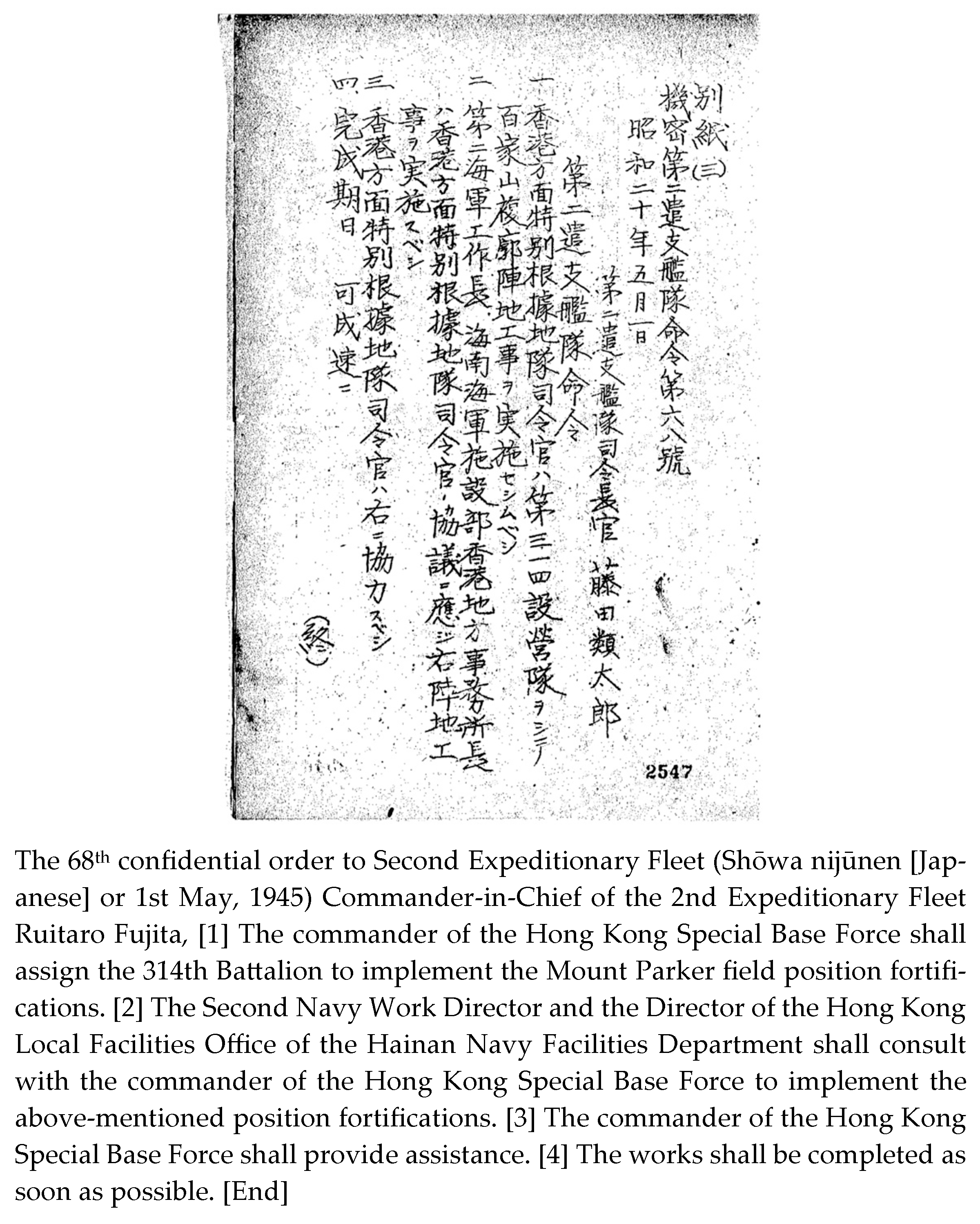
Figure 1. Wartime diary from 1–30 May 1945, 314th Construction Battalion [3].
Heritage 08 00294 g001
Figure 10. Features of war found in Mount Cameron. (a) A map indicates the location of features of war. (b) Aerial photo of Mount Cameron taken in 1963. (Feature in red rectangle is study structure). (c) Location of position in DTM-RRIM. (dg) TLS 3D mesh model of structure.
Heritage 08 00294 g010aHeritage 08 00294 g010b
Figure 11. The map indicated the location of the studied features of war.
Heritage 08 00294 g011
Figure 12. Kamikaze Grotto in Sok Kwu Wan. (a) Location of the grotto and surroundings. (b) The grotto in DTM-RRIM. (c) The grotto in aerial photo taken in 1963. (dg) TLS 3D mesh model of the grotto.
Heritage 08 00294 g012aHeritage 08 00294 g012bHeritage 08 00294 g012c
Figure 13. Discovered tunnel in Mount Stenhouse. (a) Aerial photo of the tunnel taken in 1963. (b) The tunnel overlay with DTM-RRIM. (c) Angle of view taken at tunnel entrance. (dg) TLS 3D mesh model of the grotto.
Heritage 08 00294 g013aHeritage 08 00294 g013b
Table 1. Survey equipment and acquisition parameters.
Equipment UsedAcquisition Parameters
Lecia RTC 360
(Static Laser Scanner)
Field of view360° (Horizontal)/300° (Vertical)
RangeMin 0.5 m up to 130 m
SpeedUp to 2,000,000 points/second
Lecia BLK2GO
(Handheld Laser Scanner)
Field of view360° (Horizontal)/270° (Vertical)
RangeMin 0.5 m up to 25 m
Measurement Rate420,000 points/second
Table 2. Physical parameters of the MP-A.
Latitude of Entrance A (DDD.DDDD)22.272175434
Longitude of entrance A (DDD.DDDD)114.219708052
Latitude of entrance B (DDD.DDDD)22.272007483
Longitude of entrance B (DDD.DDDD)114.219739321
Size of the tunnels0.804 m~0.871 m (Width) × 1.208 m~1.313 m (Height)
Distance between two entrances18.294 m
Size of protrusion 11.094 m (Width) × 1.601 m (Height) × 1.672 m (Depth)
Size of protrusion 20.565 m (Width) × 1.492 m (Height) × 0.974 m (Depth)
Size of protrusion 30.731 m (Width) × 1.478 m (Height) × 0.612 m (Depth)
Size of protrusion 40.918 m (Width) × 1.438 m (Height) × 1.225 m (Depth)
Total length of the tunnel34.264 m
DirectionEntrance facing N 45° E (left entrance) and N 40° E (right entrance)
Table 3. Physical parameters of the MP-B.
Latitude of Tunnel Entrance (DDD.DDDD)22.272132887
Longitude of tunnel entrance (DDD.DDDD)114.219791385
Size of the entrance of tunnel1.664 m (Width) × 0.603 m (Height)
Width of the tunnel (End of tunnel)2.656 m
Size of the protrusion2.160 m (Width) × 1.667 m (Height)
Length of the tunnel21.730 m
DirectionEntrance facing N 44° E
Table 4. Physical parameters of the MP-C.
Latitude of Tunnel Entrance A(DDD.DDDD)22.272682542
Longitude of tunnel entrance A (DDD.DDDD)114.219394304
Latitude of tunnel entrance B (DDD.DDDD)22.272589340
Longitude of tunnel entrance B (DDD.DDDD)114.219929847
Size of north entrance2.396 m (Width) × 2.041 m (Height)
Size of east entrance2.434 m (Width) × 1.220 m (Height)
Size of the middle part of the tunnel2.124 m (Width) × 2.280 m (Height)
Length of tunnel (excluding the protrusions)67.482 m
Size of west protrusion2.372 m (Width) × 2.263 m (Height)
Length of west protrusion6.668 m
Size of middle protrusion2.215 m (Width) × 2.250 m (Height)
Length of middle protrusion32.990 m
Size of east protrusion2.430 m (Width) × 2.228 m (Height)
Length of east protrusion5.520 m
Direction of north entranceFacing N 1° W
Direction of east entranceFacing N 80° E
Table 5. Physical appearance of the newly found tunnel in Wong Nai Chung Gap.
Latitude of Tunnel Entrance (DDD.DDDD)22.259737356
Longitude of tunnel entrance (DDD.DDDD)114.198116202
Entrance size0.987 m (Height) × 0.673 m (Width)
Length of tunnel14.490 m
DirectionEntrance facing S 46° W
Table 6. Physical Parameters of Structure in Mount Cameron.
Latitude of Structure (DDD.DDDD)22.263288557
Longitude of structure (DDD.DDDD)114.175048670
Largest size of the structure3.610 m (Width) × 2.932 (Long)
Height of the pillbox1.073 m
Height of the structure including tunnel2.452 m
Vertical distance between loophole to tunnel floor 1.733 m
Size of tunnel’s entrance (vertical view)1.120 m (Width) × 1.341 m (Long)
Size of tunnel’s entrance (horizontal view)1.745 m (Height) × 0.961 m (Width)
Depth of the tunnels6.967 m
Size of loopholes facing east0.226 m (Height) × 0.181 m (Width)
Size of loopholes facing south0.256 m (Height) × 0.251 m (Width)
Direction of two loopholesToward 178° and toward 270°
Table 7. Physical parameters of Kamikaze Grotto.
Latitude of Grotto Entrance (DDD.DDDD)22.204181646
Longitude of Grotto entrance (DDD.DDDD)114.127529558
Entrance size of grotto3.556 m (Width) × 2.156 m (Height)
Length of grotto28.391 m
DirectionNorth
Table 8. Physical parameter of tunnel in Mount Stenhouse.
Latitude of Tunnel Entrance (DDD.DDDD)22.194494807
Longitude of tunnel entrance (DDD.DDDD)114.129430646
Entrance size of tunnel1.020 m (Width) × 1.574 m (Height)
Length of tunnel14.158 m
Size of the first protrusion1.511 m (Width) × 1.310 m (Length)
Size of protrusion at the end of the tunnel1.252 m (Width) × 0.438 m (Length)
DirectionTowards N 80° E
Table 9. Comparison of Japanese tunnels discovered in Hong Kong to other Japanese-occupied area.
Japanese Tunnel Currently Discovered in Hong KongJapanese Tunnel Discovered in Pacific Area
LocationGenerally located inland, only few Kamikaze grotto at coastalGenerally located inland, only few Kamikaze grotto at coastal
Scale of the tunnel networkSmallExtensive
Level of tunnelSingleVaries, but some have more than 2 levels
Size of tunnel entranceSmallSmall
Length of tunnelUp to 68 mUp to 300 miles (~482 km)
Appearance of other facilities/compartments inside tunnelRarelyUsually
Appearance of second entranceSometimesAlways
Material of ceilings and wallsNo artificial material is foundMixture of rock and cement
Appearance of electricityNoSometimes
Disclaimer/Publisher’s Note: The statements, opinions and data contained in all publications are solely those of the individual author(s) and contributor(s) and not of MDPI and/or the editor(s). MDPI and/or the editor(s) disclaim responsibility for any injury to people or property resulting from any ideas, methods, instructions or products referred to in the content.