Article

Multimodal Imaging for Wooden Panel Painting Analysis: Consegna della regola Francescana by Colantonio, a Case Study

1
Institute of Applied Sciences and Intelligent Systems “E. Caianiello” of CNR, via Campi Flegrei 34, 80078 Pozzuoli, Italy
2
Institute of Cultural Heritage Sciences of CNR, via Cardinale Guglielmo Sanfelice 8, 80134 Naples, Italy
*
Author to whom correspondence should be addressed.
Heritage 2025, 8(4), 118; https://doi.org/10.3390/heritage8040118
Submission received: 14 February 2025 / Revised: 23 March 2025 / Accepted: 25 March 2025 / Published: 26 March 2025

Abstract

:
The development of advanced diagnostics tools for investigating artworks and monitoring their health state in a non-destructive way is a key point for their preservation and restoration. Non-invasive diagnostic approaches enable the identification of damage often hidden to restorers’ naked eyes, thereby facilitating the planning of appropriate restoration interventions. Here, the combined use of three full-field imaging techniques: shearography, thermography, and structured-light 3D scanning, has been employed as complementary tools for the diagnostics of a panel painting. As a case study, the artwork Consegna della regola Francescana, created by the Neapolitan painter Colantonio around 1445, was analyzed. The integrated application of the mentioned optical imaging techniques allows a comprehensive evaluation of the state of conservation of the work, revealing inserts, nails, and detachments. This synergistic approach also enhanced the interpretation of the results from each individual technique, offering a more complete understanding that would be unattainable with any single method alone.

1. Introduction

Restoring an artwork is a unique and irreplaceable act, requiring meticulous planning in every aspect. The restoration process involves various steps prior to working on the artwork, with most operations being delicate and irreversible, like cleaning and consolidation. The first step involves understanding the construction methods of the artwork to identify the materials used and how they may deteriorate or become harmed. This is followed by a careful analysis of the art piece to determine its current condition, although certain anomalies and defects may not be immediately visible. In recent years, several diagnostic techniques, especially non-destructive ones, have gained significant popularity for safely inspecting artworks and effectively planning restoration efforts without causing any harm [1].
The ability to investigate the specimen from the front side to acquire a structural understanding of artworks appears especially interesting. In fact, a knowledge of the support of structural conditions and of the deeper painting layers, which are not always easily accessible, is crucial to the long-term preservation of cultural heritage.
To this end, different imaging techniques have been employed. Speckle interferometry [2], shearography [3], and holography [4] provide interferometric resolution displacement data on the object under loading. The X-ray radiography [5] gives a non-invasive measurement of the internal structure of art objects, and X-ray spectroscopy [6,7,8] is widely used to detect, e.g., under-drawings, cracks, and knots even if it cannot, however, detect detachments. Some studies in the literature have demonstrated that the integration of optical techniques and infrared imaging is highly effective in providing complementary insights, enabling a clearer and more comprehensive understanding of both the artwork’s condition and the technical aspects of its creation and composition [9,10].
This study aims to demonstrate the potential of integrating three non-invasive imaging techniques, shearography, active thermography, and structured-light 3D scanning, for the analysis of wooden panel paintings by applying them to real artwork as a case study.
Shearography (SH) is a speckle interferometric technique widely used in automotive, aerospace, and industrial fields for quality control and structural evaluation [11]. The SH feasibility in art conservation for the structural diagnosis of panel painting has been demonstrated using an artificial sample constructed to simulate original artworks in ref. [12]. In this work, we demonstrate SH effectiveness in detecting cracks, dis-homogeneities, nails, and detachments on the surface and subsurface of a real wooden panel painting.
3D scanning is a process that uses technology to collect information about the shape and color of the object being scanned [13]. The information gathered assists in creating digital 3D designs. Structured-light 3D (SL3D) scanning is a non-invasive and non-destructive technique for gathering data, enabling the speedy and precise generation of 3D digital models [14]. The 3D survey allows us to obtain a profilometry of the panel surface and other geometrical information of the art piece. The results provide additional details on the wooden backing and insights into past restorations and emphasize the importance of the pictorial transfer method.
Active thermography (AT) is a well-established, non-destructive, and contactless infrared imaging method recognized for its efficiency and ease of implementation, making it particularly suitable for in situ analysis of artworks [15,16,17,18,19]. In AT, an external heat source is used to stimulate the surface of the sample under investigation, inducing a dynamic thermal response that is captured and recorded using an infrared camera. When applied to paintings, this technique is highly effective in detecting a wide range of defects, including inclusions, cracks, detachments, embedded nails, and other anomalies that alter the thermo-physical properties of the investigated object [20,21,22,23,24]. Here, a long-pulse thermal stimulation approach is employed, and the acquired thermal images are analyzed in the temporal dimension using thermal recovery trend methods [25,26]. The integration of active thermography with shearography has shown remarkable effectiveness for non-destructive testing (NDT) within industrial settings, especially when evaluating composite materials [27,28,29]. However, its application to cultural heritage remains considerably underutilized despite significant potential advantages.
By leveraging the complementary and mutually reinforcing capabilities of these three techniques, we aim to offer a more comprehensive understanding of both the technical and historical aspects of the analyzed artworks. To achieve this, we conducted an in situ analysis of a 15th-century panel painting titled Consegna della regola Francescana by Colantonio, which has recently been studied using other non-invasive methods [30]. This allows us to validate the effectiveness of this multimodal approach in a practical context, demonstrating its advantages for the examination and conservation of such paintings. The data acquired through the three imaging techniques, SH, SL3D Scanning, and AT, are compared and discussed, emphasizing their complementary nature in providing a more thorough understanding of the painting’s features. The integrated approach proposed here enabled the detection of a range of defects and anomalies within the artwork, providing valuable pre-restoration insights.

2. Materials and Methods

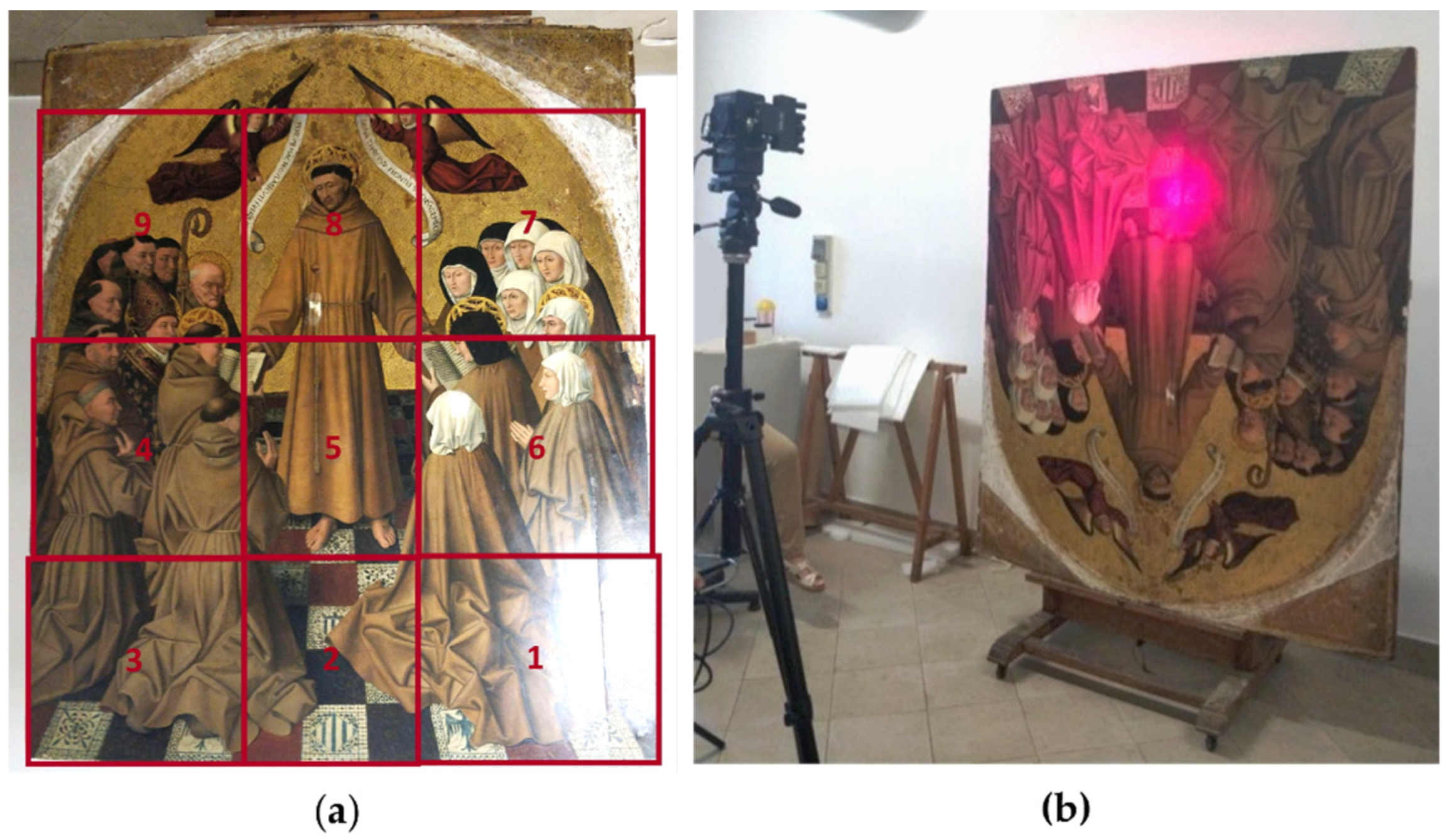
2.1. Wooden Panel Painting

The analyzed panel painting, titled Consegna della regola Francescana, is attributed to the artist Colantonio. Created around 1445, the artwork is currently housed in the Royal Museum of Capodimonte in Naples. Measuring 150 × 177 cm, the painting was virtually divided into multiple inspection zones during analysis to enhance the spatial resolution of the data obtained. This artwork was originally part of a large polyptych created by Colantonio for the prominent Church of San Lorenzo in Naples. It was commissioned by Alfonso V d’Aragona, whose coat of arms is depicted on the rajoletas, the traditional tiles commonly used for pavements in Valencia, Spain. The scene depicts San Francesco centrally placed in the artworks, standing before a golden background wearing his brown tunic and transferring the governance of his order to the Franciscan brothers on the left and to the Clarisse sisters on the right.
Niccolò Antonio, referred to as Colantonio, was the main Neapolitan artist of the 15th century and a key figure of the southern Renaissance. Colantonio was operating in Naples from 1440 to 1460, during the reign of King Renato d’Angiò and later of King Alfonso V d’Aragona, when Naples was among the most significant political and cultural centers in Mediterranean Europe. The first king, Renato d’Angiò, had a preference for Flemish, Burgundian, and Provençal art, while the second king, Alfonso V d’Aragona was more interested in the art of Catalonia, which was directly inspired by Flemish art [31,32]. The artwork is formed by three big wooden panels and one smaller panel. The medium, still under study, probably includes a combination of oil and tempera, and there is gold foil in the upper section of the composition (Figure 1).

2.2. SH Technique

SH [33,34] is a full-field speckle interferometry technique sensitive to displacement gradient. The light scattered from the object surface forms a speckle pattern, which is imaged through a shearing interferometer, interferes with its shifted duplicate, and produces a fringe pattern. This method relies primarily on a Michelson interferometer [35] and a coherent laser beam to illuminate a surface that is subjected to static or dynamic displacement due to an external perturbation. A computer-based system tracks and stores the original and perturbed positions of the surface that have shifted, allowing for continuous monitoring of surface reactions at different time points. The PC-driven recording process depends on multiple surface datasets known as phase maps, indicating the surface out-of-plane displacement derivative in space and time with varying operating parameters and induced excitation. When evaluating artworks, the stimulus should be slight yet effective in inducing motion. Changes in strain on art pieces stored in stable conditions can be caused by surface imperfections and overall dimensional movements like shrinkage or expansion [36].
The used setup shown in Figure 2 is based on the ISI-SYS SE5 system with a 5.1 MP cmos camera and red laser diode array (class 1). The thermal loading is obtained by two halogen flood lights (2 × 1000 W). The excitement is caused by heat stimulation at a secure distance to avoid causing damages but enough to create object displacement.
Measurements are taken prior to restoration when only a few cleaning tests have been conducted. The removal of the initial layer of varnish is insignificant for the shearography measurement purpose. The painting is virtually divided into nine sections, each section being measured using our portable shearography instrument (Figure 3). Even though SH is primarily a surface inspection technique, subsurface and bulk defects can sometimes influence the surface-level signal. SH therefore is able to evaluate the condition of wooden panel paintings, identifying cracks, inconsistencies, and separations on both the surface and subsurface layers.

2.3. SL3D Scanning Method

The SL3D scanner can capture the three-dimensional shape of an object by projecting light patterns, usually stripes, onto its surface and measuring the deformations of these patterns due to the object’s curves, depressions, or raised areas. (Figure 4). The scanning software analyzes the distorted patterns and converts them into 3D coordinates that show the specific location of the object surface being scanned. The result of the scanning process is a group of points, each having their own set of coordinates, which is referred to as a point cloud.
Several scans are required to accurately capture the object’s shape, including its detailed engravings and reliefs. To achieve this, the shape of the object is thoroughly analyzed, experiments are carried out, and a customized scanning approach is employed for every item depending on the test results and scanning space accessible [13,38].
The Eva Artec 3D device, suited to scan and generate 3D models of medium to large objects, is used. The size of the wooden panel painting allows us to cover the entire surface with just four scans of the front and back. The used scanner offers fast caption speed (16 FPS), a 3D resolution of 0.2 mm, and high-resolution texture (1.3 MP) The term texture refers to the object’s colors and other visible surface characteristics that are acquired by an additional camera. The Eva scanner, in fact, does not function exactly as depicted in Figure 4; it operates with two cameras and the projector aligned parallel to each other, providing greater accuracy and the ability to capture more scans simultaneously. The purpose of this measure is to ensure a detailed resolution of both the 3D model, pertaining to a mesh consisting of vertices, edges, and faces, and its texture. Adding various textures can enhance the realism of the scan, with the scanner texture accurately displaying colors at the expense of geometry details, even though the unedited version gives information on the state of the artwork’s surface. The software enables the incorporation of photogrammetry texture to enhance detailed information while reducing data loss on surface geometries [39]. The 3D data platforms manage the scanned object files cautiously and are accessed in a similar way due to the large amount of data produced by 3D scans that traditional platforms cannot store. Instruments are given for assessing distances or modifying texture, and the documents can be utilized for further processing and extraction.

2.4. AT Measurement Setup

AT analysis is carried out, virtually dividing the painting into 15 inspection areas, each measuring approximately 50 × 40 cm. In each area, the same protocol for both measurements and image processing is applied. The experimental setup utilized a halogen lamp with adjustable power (maximum output of 1 kW) to deliver thermal pulses of 20 s, inducing temperature increases within the range of 1 °C ≤ ΔT ≤ 5 °C. Thermal imaging was recorded using a FLIR X6580 sc (FLIR Systems Inc., Wilsonville, OR, USA) infrared camera equipped with a cooled indium antimonide (InSb) detector, operating in the mid-wave infrared region (MWIR, 3.5–5 μm), and a focal plane array (FPA) with a resolution of 640 × 512 pixels, a field of view (IFOV) of 0.3 mrad, and a noise equivalent temperature difference (NETD) of approximately 20 mK at 25 °C. A 50 mm focal length lens was used to capture thermal frames at a rate of 10 Hz before, during, and after heating for about 60 s. The ResearchIR software (FLIR Systems Inc., Winsonville, OR, USA) was used to manage the camera settings and to monitor the temperature in real time. The recorded thermal sequences were subsequently utilized for a mosaic reconstruction of the painting and the calculation of 2D thermal recovery maps (TRMs) following a similar approach used in previous works [17,18]. For TRMs calculation, the thermal image sequences were processed using home-made MATLAB (R2019a) scripts, running on a computer equipped with an Intel i7-4770 processor at 3.40 GHz (8 cores) and 32 GB of RAM, which ensured efficient data handling and processing capabilities.

3. Results

The three techniques considered were used to inspect the various areas into which the painting was virtually divided. The objective of this analysis is to detect potential structural issues and defects while also validating the advantages of combining SH, SL scanning, and AT. This multimodal approach enables a more detailed and complementary evaluation of the surface, subsurface, and structural characteristics of the artwork. By applying these techniques to Colantonio’s painting, we aim to demonstrate their effectiveness in providing comprehensive diagnostic information that can support conservation strategies. The key results obtained from the analysis using the three techniques used are presented and discussed in the following three sections: surface, subsurface, and structural information, respectively. It should be noted that by “surface layer”, we refer to the external layer of the painting, visible to the naked eye and in direct contact with the air, while by “subsurface layers”, we refer to the layers immediately beneath the surface, which include the pictorial layer not in direct contact with air, as well as the preparation layers. Finally, the “Structural information” section is devoted to results pertaining to the wooden panels.

3.1. Surface Information

By the 3D model, obtained through the SL3D Scanning, it is possible to obtain a profilometry of the panel surface to enhance our understanding of the painting technique and other features of the artwork. This measurement shown in Figure 5 allows us to reveal the complexity of the processing steps. In fact, around 1400, the transition began from using tempera paint to using oil paint, which held pigment suspension in oil instead of egg. It appears that this new method began in Flanders, and well regarded artworks by Flemish artists were also recognized, esteemed, and acquired in Italy. So Colantonio knew these artworks and had been inspired by them and their techniques. This case study includes a blending of media because artists during this period commonly utilized both techniques, sometimes simultaneously.
Getting the table ready for the paintings involves smoothing out the wooden surface and adding multiple layers of plaster and glue before, finally, applying the paint. Gold foil is also present at the top of this panel painting. In artworks where a golden element is required, the preparation for the golden sheet, named ‘bolo’ (clayey soil mixed with egg white and water, applied in three or four layers from liquid to thick), is added after the final layer of gypsum and glue, followed by the application of the golden leaf [40]. Afterward, a scalpel or sharp tools are used to make incisions to separate the golden lamina section from the painted section that will be created from that point.
By 3D model, we note that there is a distinction in the number of details between the upper section, which is more defined, and the lower section of the artwork, which is less defined. This is also confirmed by the thermographic analysis, shown in the following section.

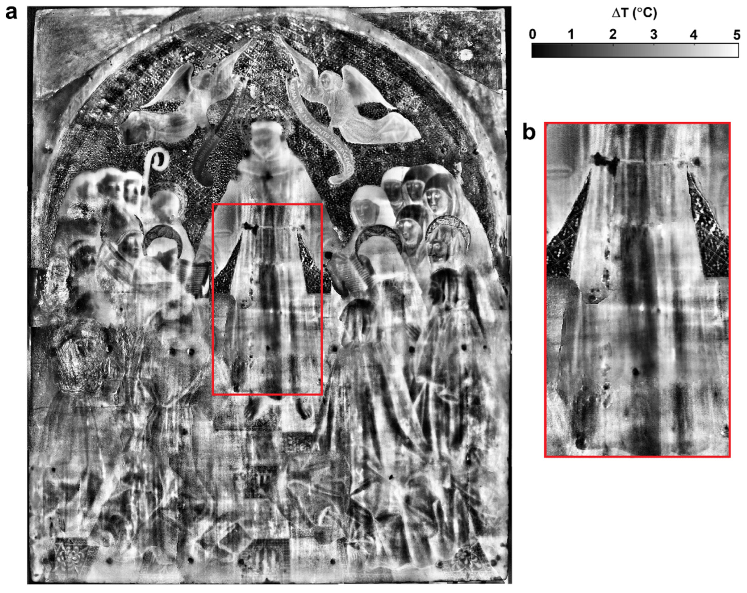
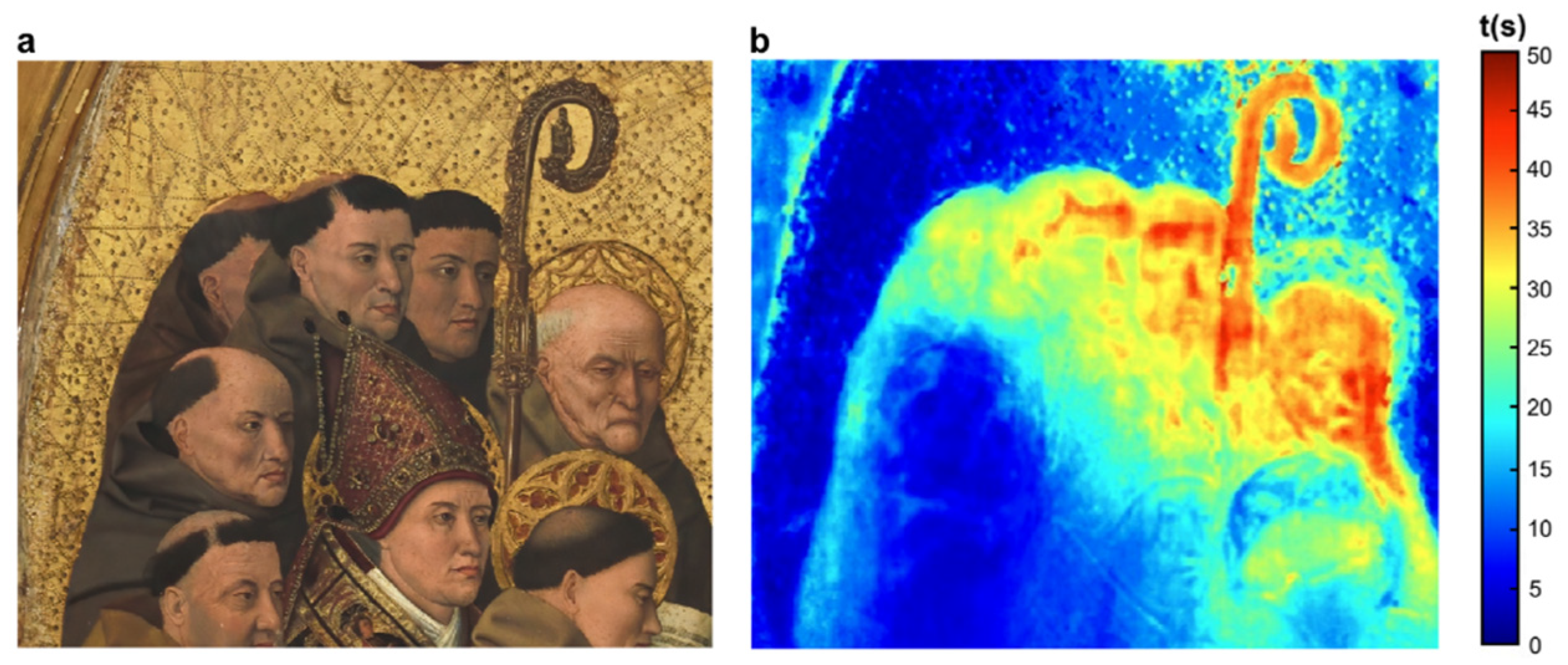
3.2. Subsurface Information

The AT protocol described in Section 2.4 is used to investigate each of the 15 areas into which the panel painting artwork is virtually divided. Subsequently, the acquired thermal data are analyzed with two different processing approaches.
The first approach carried out is based on the calculation of the maximum temperature gradient (MTG) map. To this aim, for each of the 15 thermal sequences recorded, the ΔTmax is calculated with the following relationship:
ΔTmax(i,j) = Tmax (i,j) − T0 (i,j)
where T0 is the temperature of the pixel with coordinates (i,j) measured in the frame captured immediately before the lamp is switched on, and Tmax is the temperature of the same pixel measured in the frame captured after it is switched off.
The 15 processed images thus obtained are subsequently merged into a single final overall map shown in Figure 6.
Observing the map in Figure 6a as a whole, it can be noted that despite all areas being investigated following the same measurement and analysis protocol, the upper half of the map appears more defined and less noisy compared to the lower half. This difference can be observed in detail in the close-up of San Francesco’s dress, shown in Figure 6b, located between the two halves of the painting. This anomalous response can likely be attributed to a different preparation process used by the artist for the subsurface layers of the two halves of the painting. It can be reasonably presumed that the application of a gold-leaf background to the upper half of the painting (as visible in the final image) led the artist to perform more pronounced sanding of the preparatory layers in that area. From a thermo-optical point of view, this results in a variation in emissivity between the two parts of the painting, causing a different response to the induced thermal stress. Consequently, the two halves show both different reflectivity and, consequently, a different signal-to-noise ratio.
A further analysis of the thermal data is conducted using the calculation of the TRMs, following a similar methodology described in previous studies [25,26]. First, the ΔTmax was calculated for each pixel of the thermal frames using Equation (1). Next, the temporal behavior of each pixel was analyzed to estimate the time required for it to recover a fixed percentage of its respective ΔTmax. For each thermal sequence analyzed, the percentage threshold was chosen within the range of 20–40% to optimize both variation in recovery times across the map pixels and the overall contrast.
The TRM in Figure 7 shows an area characterized by a noticeably higher recovery time (yellow–red colored). It can be observed that this area precisely outlines the heads of the four characters in the upper part of the painted group, as well as some elements like the staff. This correspondence leads to the reasonable assumption that, unlike the previous cases, the elevated recovery time may be associated with a thicker paint stratigraphy, whose greater thermal inertia results in slower thermal recovery. This result could suggest that in this area of the painting, a new paint layer was applied over an earlier one to modify, even partially, this part of the artwork. Analyses of this area performed by other investigation methods do not reveal any anomaly or spatial dis-uniformity, showing how the different techniques provide complementary results.
Other subsurface information is recovered by the SH analysis. In fact, due to the SH measurement, we detect a significant amount of grouting in this artwork. Figure 8 shows the visible image (Figure 8a) and the corresponding SH image (Figure 8b) of the central area of the painting. Even though SH is primarily a surface inspection technique, subsurface defects can sometimes influence the surface-level signal. In the SH image, some areas presumably affected by grouting are visible (circled in green in Figure 8b), likely resulting from previous chromatic retouching. Figure 8c shows the MTG map corresponding to an enlarged view of San Francesco’s dress (red rectangle in Figure 8a). This map highlights several areas with an anomalous thermal response (circled in red) of irregular shape and dimensions up to several millimeters. These anomalous responses can be attributed to the presence of materials of a different nature, such as stucco, compared to the wooden matrix, thereby supporting and confirming the hypotheses formulated through the SH analysis. Some of these grouted areas are camouflaged and not visible to the naked eye, thus affecting the subsurface layers of the painting.

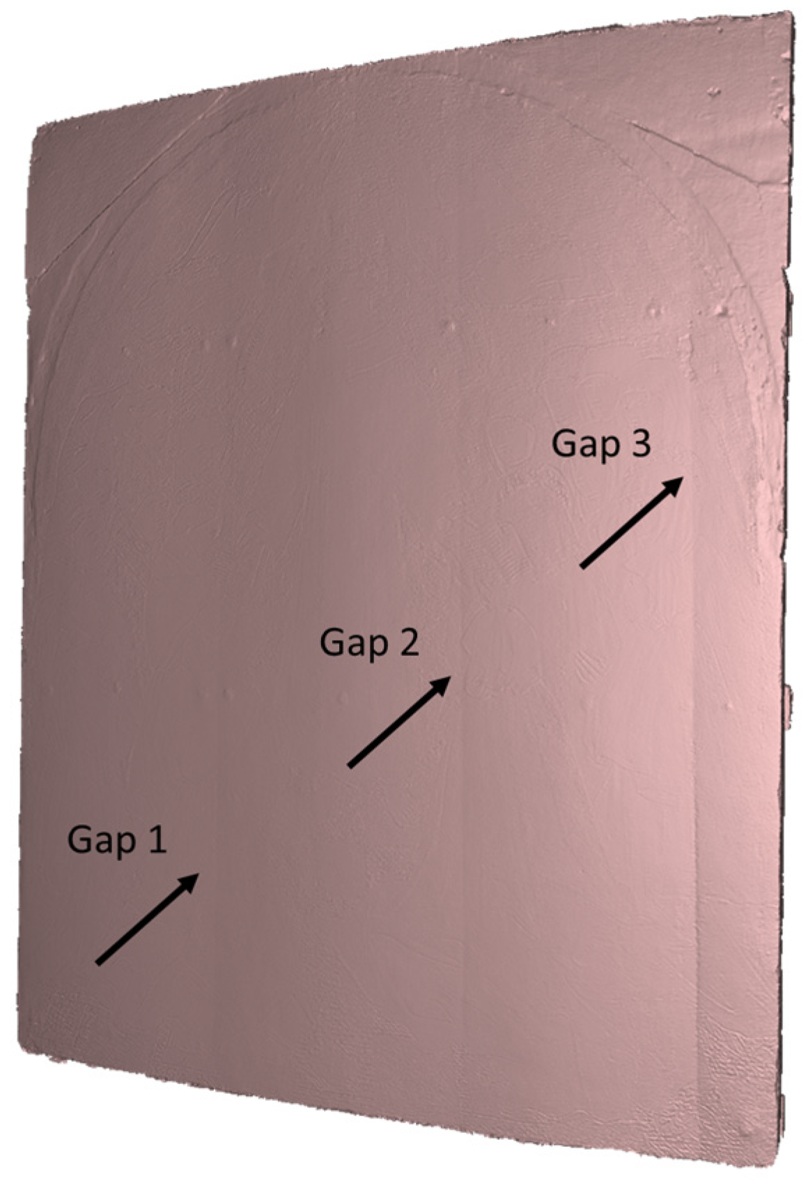
3.3. Structural Information

Through the SL3D scanning model at the 1:1 scale, we can take accurate measurements of the artwork as to, e.g., its thickness, which results to be 3.8 cm. Additionally, we can determine the position of the junctions between the wooden panels that constitute the painting’s support (Figure 9).
The texture-free 3D model represents a valuable resource for examining the structure of the artwork. It highlights a structural problem affecting the investigated artwork: the vessel, which refers to the inclination of wooden boards to bend to varying degrees; the planks have warped, a phenomenon caused by the sensitivity of wood to changes due to the environmental conditions. Using the 3D model, we measure the panel curvature radius, which results to be about 8.5 m. The gaps between the panels are also revealed by AT and SH.
Further thermal data analysis is conducted on the areas of the painting where there are gaps between wooden panels using TRMs. Figure 10 shows visible images of two areas of the painting analyzed (first column) and the corresponding TRMs obtained (second column).
The TRM in Figure 10a highlights a linear area (circled in black) characterized by recovery times that are visibly higher than those of other areas on the map. As shown, this area extends mainly in a vertical direction, with partial horizontal diffusion. A comparison on site with the painting confirmed that this area with anomalous thermal recovery corresponds to the joint between two of the four wooden panels that form the support of the painting. The higher recovery times can be associated with the presence of subsurface air gaps that, due to their lower thermal conductivity (~0.02 W/m K) compared to that of the wood (~0.2 W/m K), act as an insulator, slowing down the heat dissipation process and thus increasing the recovery times associated with these areas of the painting. The presence of these air gaps in these areas of the painting can be due to (a) lower adhesion of the paint layer caused by the deformation exhibited by the panels in these areas and (b) the presence of widespread woodworm damage, which, as is well known to expert restorers, tends to be more prevalent in the joints. A similar result is obtained for the area of the painting shown in Figure 10b. In this case, two anomalous areas are detected (circled in black), both corresponding to joints between the wooden panels of the support. This last area is also inspected using SH (Figure 11b) and SL3D-Scattering (Figure 11c). Comparing these results to the visible image in Figure 11a, we note, in addition to the gap between panels (yellow rectangles), two other structural defects that probably correspond to nails (circled in green).
Subsequently, AT analyses confirmed this hypothesis. Figure 12 shows the visible images (Figure 12a) and the corresponding MTG maps (Figure 12b) and TRMs (Figure 12c) of two different areas of the painting. The left column corresponds to an enlargement of the area shown in Figure 11a investigated by SH and 3D-S.
It can be observed that in both MTG maps, several circular elements (in black) are visible, showing a low ΔT. These elements could represent nails within the structure used to secure the various panels constituting the wooden support of the painting. This hypothesis is supported by the TRMs, which show lower recovery times at these elements compared to the surrounding areas. This result is consistent with the metallic nature of the nails, which, due to their thermal properties (high thermal conductivity), allow heat diffusion and faster thermal recovery. This example highlights how the integrated use of the three different investigation techniques considered here facilitates the identification and interpretation of anomalies detected through more basic analyses.
Wooden panel paintings are often infected by wood worms that consume the wood’s grain. We suggest that shearography can detect not only the well-known wormholes but also remnants of the air tunnels. Figure 13 shows the visible image (Figure 13a) and the corresponding SH (Figure 13b) and MTG (Figure 13c) images of an area of the painting, probably affected by woodworms, which shows several anomalies by means of both techniques.
In particular, the SH analysis highlights areas (circled in green in Figure 13b) likely affected by woodworms that are not visible to the naked eye in the corresponding regions of the painting (circled in white in Figure 13a). The MTG map reveals in these same regions of the painting, areas not corresponding to pictorial features that show an anomalous thermal response, characterized by a higher ΔTmax (white areas within the red circles in Figure 13c), likely caused by the presence of air gaps associated with the wormholes.

4. Discussion and Conclusions

This study demonstrates the effectiveness of an integrated approach combining shearography (SH), active thermography (AT), and structured-light 3D scanning (SL 3D scanning) for the non-destructive analysis of wooden panel paintings.
The techniques used have common important characteristics such as non-destructivity, accuracy, and repeatability and features such as non-contact, portability, high resolution for defect detection, and structural investigation. It allowed us to apply them in situ without damage or altering the artwork to analyze the 15th-century panel painting Consegna della Regola Francescana by Colantonio, housed in the Royal Museum of Capodimonte in Naples, providing a comprehensive diagnostic framework that enhances both structural and technical assessments of artwork, preparatory for its conservation-restoration work.
The results highlight the complementary nature of these three imaging techniques, which allowed us to uncover a range of defects and structural issues in the analyzed artwork that are otherwise difficult to detect and identify by any single technique alone.
SH proved highly effective in detecting subsurface anomalies such as grouting, likely from previous restoration efforts, and the presence of nails and woodworm holes in the structure, which was corroborated by the SL3D Scanning and AT analyses. AT provided detailed thermal response maps that helped identify hidden structural defects, previous restorations, woodworm damage, and air gaps. In addition, differences in the thickness and stratigraphy of preparation and painting layers are highlighted as regions of alteration in the thermal properties. Meanwhile, SL3D scanning enabled surface profilometry and revealed the geometric characteristics of the wooden panel, including warping and junctions.
The complementarity of the techniques, in particular AT and SH, is possible due to the difference in the physical phenomena that they detect, i.e., respectively, thermal response and surface deformation. Some object features are evident only by one technique, while others are detected in both. The latter case provides the possibility to compare the results, resolving possible ambiguities in the interpretation of the measurements. This is a notable advantage as it can aid the interpretative effort of the operator. Thus, the integration of these three techniques facilitated both the identification and the classification of a wide range of defects that may not be immediately visible to the naked eye but are crucial for planning conservation/restoration interventions.
These findings align with those from previous studies that applied similar techniques for non-invasive artwork analysis. For example, digital holographic speckle pattern interferometry (DHSPI) coupled with stimulated infrared thermography (SIRT) proved to be a powerful non-invasive, non-contact, full-field, subsurface diagnostics system for a variety of works of art, such as marquery or wall mosaic; however, to the authors’ awareness, most of the experiments have been performed in laboratory on sample models in order to validate the effectiveness of the investigation technique [9,10,12,41,42]. A limitation of the DHSPI technique that makes in situ applications difficult is its high sensitivity to surrounding vibrations. Compared to DHSPI, the SH technique is more stable with respect to environmental vibrations because of its self-referenced setup geometry, but, at the same time, it maintains the non-destructive, non-contact, full-field characteristics. In fact, it has already been successfully applied to the in situ investigation of wall paintings and canvas [43,44].
We make a step forward, demonstrating the effectiveness of SH for the in situ investigation of panel painting; moreover, the integration of SH and AT, as already stated in ref. [28] for the case of industrial applications, provides a more comprehensive approach, overcoming the limitations of each method when used independently.
In addition to the numerous benefits the multimodal approach offers, it also presents some limitations, e.g., integrating data from multiple techniques requires significant interpretive expertise to ensure the consistency of the findings.
Beyond its application to this case study, the proposed approach has broader implications for heritage conservation. By leveraging portable, non-invasive techniques, conservators and researchers can obtain critical diagnostic information in situ, supporting informed decision making regarding the restoration interventions and the application of micro-invasive analysis. This methodology can be extended to various historical artworks, including those with complex stratigraphy or composite materials, where conventional analysis techniques may fall short.
Future research could focus on further refining the synergy between these techniques, developing automated processing algorithms to enhance data interpretation and exploring the integration of additional portable imaging modalities, which focus similarly on the investigation of the artwork integrity and the detection of anomalies in such complex layered structures. Expanding the application of this methodology to different types of artworks and materials will further validate its robustness and potential as a standard practice in preventive conservation and restoration planning.

Author Contributions

C.S.: Investigation, formal analysis, data curation, visualization, writing—original draft; A.D.M.: investigation, visualization, data curation, writing—review and editing; M.R.: conceptualization, investigation, formal analysis, data curation, resources, visualization, writing—original draft; V.P.: conceptualization, investigation, resources, formal analysis, writing—review and editing; T.C.: conceptualization, resources, writing—review and editing; M.P.: writing—original draft, writing—review and editing, funding acquisition, investigation, resources, conceptualization. All authors have read and agreed to the published version of the manuscript.

Funding

This research was funded by European Union-Next Generation EU, Missione 4 Componente 1 CUP B53D23022470006 grant number 2022CEJ348_SH5_PRIN2022—AMATI Vi(H)olin.

Data Availability Statement

The data presented in this study are available on request from the corresponding author due to the agreement with the Capodimonte museum.

Acknowledgments

We would like to thank the director and staff of the Museo e Real Bosco di Capodimonte for enabling these investigations and Intesa Sanpaolo, which is supporting the restoration as part of Restituzioni project. We thank Angela Cerasuolo (University of Siena) and the restorers Giulia Zorzetti and Paola Foglia for the helpful discussion about the experimental results interpretation. Our appreciation to Margherita Giugni (ISPC-CNR) for her willingness to share information in a true spirit of collaboration. Finally, we express our gratitude to Costanza Miliani (ISPC-CNR Director) for her contribution in facilitating connections and communication with Museum staff, as well as providing valuable feedback on the results.

Conflicts of Interest

The authors declare no conflicts of interest.

References

  1. Castillejo, M. (Ed.) Lasers in the Conservation of Artworks; CRC Press: Leiden, The Netherlands, 2008. [Google Scholar]
  2. Paoletti, D.; Schirripa Spagnolo, G.; Facchini, M.; Zanetta, P. Artwork diagnostics with fiber-optic digital speckle pattern interferometry. Appl. Opt. 1993, 32, 6236–6241. [Google Scholar] [CrossRef]
  3. Groves, R.M.; Osten, W.; Doulgeridis, M.; Kouloumpi, E.; Green, T.; Hackney, S.; Tornari, V. Shearography as part of a multi-functional sensor for the detection of signature features in movable cultural heritaged. In Proceedings of the SPIE 6618, O3A: Optics for Arts, Architecture, and Archaeology, Munich, Germany, 19 July 2007; Volume 661810. [Google Scholar] [CrossRef]
  4. Asmus, J.F.; Guattari, G.; Lazzarini, L.; Musemeci, G.; Wuerker, R.F. Holography in the conservation of statuary. Stud. Conserv. 1973, 18, 49–63. [Google Scholar] [CrossRef]
  5. Rossi, M.; Casali, F.; Golovkin, S.V.; Govorun, V.N. Digital radiography using an EBCCD-based imaging device. Appl. Radiat. Isot. 2000, 53, 699–709. [Google Scholar] [CrossRef]
  6. Dik, J.; Jassens, K.; Van Der Snickt, G.; van der Loeff, L.; Rickers, K.; Cotte, M. Visualization of a lost painting by Vincent van Gogh using synchrotron radiation- based X-ray fluorescence elemental mapping. Anal. Chem. 2008, 80, 6436–6442. [Google Scholar] [CrossRef]
  7. D’Elia, E.; Buscaglia, P.; Piccirillo, A.; Picollo, M.; Casini, A.; Cucci, C.; Stefani, L.; Romano, F.P.; Caliri, C.; Gulmini, M. Macro X-ray fluorescence and VNIR hyperspectral imaging in the investigation of two panels by Marco d’Oggiono. Microchem. J. 2020, 154, 104541. [Google Scholar] [CrossRef]
  8. Cavaleri, T.; Pelosi, C.; Caliri, C.; Romano, P.F.; Colantonio, C.; Lanteri, L.; Calabrò, G.; Piccirillo, A.; Ventura, B.; De Blasi, S.; et al. Tracing the history of past treatments: A multi-analytical study of a 16th-century panel painting copy after Raphael. J. Cult. Herit. 2024, 66, 142–154. [Google Scholar] [CrossRef]
  9. Sfarra, S.; Theodorakeas, P.; Castanedo, C.; Avdelidis, N.; Paoletti, A.; Paoletti, D.; Hrissagis, K.; Bendada, A.; Koui, M.; Maldague, X. Evaluation of defects in panel paintings using infrared, optical and ultrasonic techniques. Insight Non-Destr. Test. Cond. Monit. 2012, 54, 21–27. [Google Scholar] [CrossRef]
  10. Tornari, V.; Andrianakis, M.; Hatzigiannakis, K.; Kosma, K.; Detalle, V.; Bourguignon, E.; Giovannacci, D.; Brissaud, D. Complementarity of digital holographic speckle pattern interferometry and simulated infrared thermography for Cultural Heritage structural diagnostic research. Int. J. Eng. Res. Sci. (IJOER) 2016, 2, 129–141. [Google Scholar]
  11. Francis, D.; Tatam, R.P.; Groves, R.M. Shearography technology and applications: A review. Meas. Sci. Technol. 2010, 21, 102001. [Google Scholar] [CrossRef]
  12. Groves, R.M.; Pradarutti, B.; Kouloumpi, E.; Osten, W.; Notni, G. 2D and 3D Non-Destructive Evaluation of a Wooden Panel Painting Using Shearography and Terahertz Imaging. NDT E Int. 2009, 42, 543–549. [Google Scholar]
  13. Jončić, N.; Zachar, J. 3D Scanning, in 3D Digital Recording of Archaeological, Architectural and Artistic Heritage; Znanstvena Založba Filozofske Fakultete: Ljubljana, Slovenia, 2017; pp. 23–32. [Google Scholar]
  14. Saltarelli, C.; Rippa, M.; Pagliarulo, V.; Vigorito, M.R.; Paturzo, M. The Heritage Building Information Modelling System for non-destructive optical techniques: The case study of the restoration of a Marble sculpture on the façade of the Gesù Nuovo Church in Naples. Akta IMECO 2025, 42, 1–8. [Google Scholar]
  15. Maldague, X.P.V. Introduction to NDT by active infrared thermography. Mater. Eval. 2002, 60, 1060–1073. [Google Scholar]
  16. Dritsa, V.; Orazi, N.; Yao, Y.; Paoloni, S.; Koui, M.; Sfarra, S. Thermographic Imaging in Cultural Heritage: A Short Review. Sensors 2022, 22, 9076. [Google Scholar] [CrossRef]
  17. Orazi, N. The study of artistic bronzes by infrared thermography: A review. J. Cult. Herit. 2020, 42, 280–289. [Google Scholar] [CrossRef]
  18. Vavilov, V.P.; Bison, P.G.; Burleigh, P.G.D.D. Ermanno Grinzato’s contribution to infrared diagnostics and nondestructive testing: In memory of an outstanding researcher. Quant. InfraRed Thermogr. J. 2023, 21, 338–351. [Google Scholar] [CrossRef]
  19. Paoloni, S.; Orazi, N.; Zammit, U.; Bison, P.; Mercuri, F. A note on the early thermographic approaches for the investigation of the Cultural Heritage. Quant. InfraRed Thermogr. J. 2023, 21, 408–420. [Google Scholar] [CrossRef]
  20. Rippa, M.; Pagliarulo, V.; Lanzillo, A.; Grilli, M.; Fatigati, G.; Rossi, P.; Cennamo, P.; Trojsi, G.; Ferraro, P.; Mormile, P. Active Thermography for Non-invasive Inspection of an Artwork on Poplar Panel: Novel Approach Using Principal Component Thermography and Absolute Thermal Contrast. J. Nondestruct. Eval. 2021, 40, 21. [Google Scholar] [CrossRef]
  21. Yao, Y.; Sfarra, S.; Lagüela, S.; Ibarra-Castanedo, C.; Wu, J.Y.; Maldague, X.P.V.; Ambrosini, D. Active thermography testing and data analysis for the state of conservation of panel paintings. Int. J. Therm. Sci. 2018, 126, 143–151. [Google Scholar] [CrossRef]
  22. Laureti, S.; Colantonio, C.; Burrascano, P.; Melis, M.; Calabrò, G.; Malekmohammadi, H.; Sfarra, S.; Ricci, M.; Pelosi, C. Development of integrated innovative techniques for paintings examination: The case studies of The Resurrection of Christ attributed to Andrea Mantegna and the Crucifixion of Viterbo attributed to Michelangelo’s workshop. J. Cult. Herit. 2019, 40, 1–16. [Google Scholar] [CrossRef]
  23. Laureti, S.; Sfarra, S.; Malekmohammadi, H.; Burrascano, P.; Hutchins, D.A.; Senni, L.; Silipigni, G.; Maldague, X.P.V.; Ricci, M. The use of pulse-compression thermography for detecting defects in paintings. NDT & E Int. 2018, 98, 147–154. [Google Scholar]
  24. Di Meo, A.; Balbi, B.; Casciello, M.; Vigorito, M.R.; Mormile, P.; Rippa, M. Complementary infrared imaging methods for the structural and technical analysis of a panel painting: Adoration of the Magi by Marco Cardisco. Infrared Phys. Technol. 2025, 145, 105705. [Google Scholar]
  25. Rippa, M.; Vigorito, M.R.; Russo, M.R.; Mormile, P.; Trojsi, G. Active Thermography for Non-invasive Inspection of Wall Painting: Novel Approach Based on Thermal Recovery Maps. J. Nondestruct. Eval. 2023, 42, 63. [Google Scholar]
  26. Rippa, M.; Pagliarulo, V.; Napolitano, F.; Valente, T. Russo: Infrared Imaging Analysis of Green Composite Materials during Inline Quasi-Static Flexural Test: Monitoring by Passive and Active Approaches. Materials 2023, 16, 3081. [Google Scholar]
  27. Théroux, L.-D.; Dumoulin, J.; Maladague, X. Square Heating Applied to Shearography and Active Infrared Thermography Measurements Coupling: From Feasibility Test in Laboratory to Numerical Study of Pultruded CFRP Plates Glued on Concrete Specimen. Strain 2014, 50, 404–416. [Google Scholar] [CrossRef]
  28. Hung, Y.Y.; Chen, Y.S.; Ng, S.P.; Liu, L.; Huang, Y.H.; Luk, B.L.; Ip, R.W.L.; Wu, C.M.L.; Chung, P.S. Review and comparison of shearography and active thermography for nondestructive evaluation. Mater. Sci. Eng. 2009, 64, 73–112. [Google Scholar] [CrossRef]
  29. Sirohi, R. Shearography and its applications—A chronological review. Light Adv. Manuf. 2022, 3, 35–64. [Google Scholar] [CrossRef]
  30. Scialla, E.; Improda, P.; Brocchieri, J.; Cardinali, M.; Cerasuolo, A.; Rullo, A.; Zezza, A.; Sabbarese, C. Study of ‘Cona degli Ordini’ by Colantonio with IR and XRF Analyses. Heritage 2023, 6, 1785–1803. [Google Scholar] [CrossRef]
  31. De Vecchi, P.; Cerchiari, E. I Tempi Dell’Arte; Bompiani: Milano, Italy, 1999; Volume 2. [Google Scholar]
  32. De Castris, P. Museo e Gallerie Nazionali di Capodimonte. Dipinti dal XIII al XVI secolo. In Le Collezioni Borboniche e Post-unitarie; Electa: Napoli, Italy, 1999; pp. 55–57. [Google Scholar]
  33. Butters, J.N.; Leendertz, J.A. An image-shearing speckle-pattern interferometer for measuring bending moments. J. Phys. E Sci. Instrum. 1973, 6, 1107–1110. [Google Scholar]
  34. Steinchen, W.; Yang, L. Digital Shearography; SPIE Press: Bellingham, WA, USA, 2001. [Google Scholar]
  35. Pagliarulo, V.; Lopresto, V.; Langella, A.; Antonucci, V.; Ricciardi, M.R.; Ferraro, P. Non-destructive evaluation of impact damage on carbon fiber laminates: Comparison between ESPI and Shearography. AIP Conf. Proc. 2016, 1740, 040002. [Google Scholar] [CrossRef]
  36. Tornari, V. A symmetry concept and significance of fringe patterns as a direct diagnostic tool in artwork. Light Adv. Manuf. 2022, 3, 2689–9620. [Google Scholar] [CrossRef]
  37. Soft Serve Inc. Available online: https://www.softserveinc.com/en-us/blog/structured-light-imaging (accessed on 12 December 2024).
  38. Maravelakis, E.; Konstantaras, A.; Kritsotaki, A.; Angelakis, D.; Xinogalos, M. Analysing User Needs for a Unified 3D Metadata Recording and Exploitation of Cultural Heritage Monuments System. In Advances in Visual Computing, Lecture Notes in Computer Science; Springer: Berlin/Heidelberg, Germany, 2013; Volume 8034, pp. 138–147. [Google Scholar]
  39. Artec 3D. Available online: https://www.artec3d.com/it/learning-center (accessed on 11 December 2024).
  40. Maltese, C. Le Tecniche Artistiche; Mursia: Milano, Italy, 1983; pp. 327–333. [Google Scholar]
  41. Kosma, K.; Andrianakis, M.; Hatzigiannakis, K.; Tornari, V. Digital holographic interferometry for cultural heritage structural diagnostics: A coherent and a low-coherence optical set-up for the study of a marquetry sample. Strain 2018, 54, e12263. [Google Scholar]
  42. Chaban, A.; Tornari, V.; Deiana, R.; Andrianakis, M.; Giovannacci, D.; Detalle, V. A combined non-invasive approach to the study of a mosaic model: First laboratory experimental results. J. Imaging 2019, 5, 58. [Google Scholar] [CrossRef]
  43. Gatto, V.; Anisimov, A.G.; Lettinga, W.; Tao, N.; Lantman, M.; Crijns, B.; Groves, R.M. Application of shearography and thepercussion method for the structural inspection of wall paintings: A case study of St. Christopher in Maria Church, Nisse. In Proceedings of the SPIE11784, Optics for Arts, Architecture, and Archaeology VIII, Online, 21–25 June 2021; Volume 117840K. [Google Scholar] [CrossRef]
  44. Tao, N.; Anisimov, A.G.; Duijn, E.V.; Vos, L.; Steeman, I.; Keune, K.; Noble, P.; Groves, R.M. Application of shearography with thermal loading for the structural inspection of Rembrandt’s Night Watch. In Proceedings of the SPIE 12620, Optics for Arts, Architecture, and Archaeology (O3A) IX, Online, 9 August 2023; Volume 12620. [Google Scholar] [CrossRef]
Figure 1. Picture of the wooden panel painting, along with its frame, displayed in the restoration laboratory. Reproduced by permission of MiC-Museo e Real Bosco di Capodimonte.
Heritage 08 00118 g001
Figure 2. Sketch showing the operating principle of the shearography instrument.
Heritage 08 00118 g002
Figure 3. Pictures of the entire wooden panel placed in the conservation lab during the measurements survey: (a) Image of the recto, virtually divided in nine inspection areas; (b) Set up image. Images reproduced by permission of MiC-Museo e Real Bosco di Capodimonte.
Heritage 08 00118 g003
Figure 4. Sketch of structured light scanners functioning: I0 = structured light impinging on the object a(x,y); β1 and β2 = ambient light; I = total intensity acquired by the camera [37].
Heritage 08 00118 g004
Figure 5. Profilometry of the panel surface: blue color indicates relief areas, whereas red points are depressions compared to the average value (scale bar unit is mm).
Heritage 08 00118 g005
Figure 6. MTG images of the panel painting analyzed: (a) full map, (b) close-up of the central area depicting San Francesco’s dress.
Heritage 08 00118 g006
Figure 7. Area of the painting depicting a group of subjects: (a) visible images and (b) the corresponding TRM.
Heritage 08 00118 g007
Figure 8. Comparative Analysis of San Francesco’s dress: (a) visible image, (b) SH images, black box shows a close-up of the left hand of San Francesco, (c) MTG map.
Heritage 08 00118 g008
Figure 9. 3D-S model of the painting; without texture, the gaps of the wooden panels are quite noticeable.
Heritage 08 00118 g009
Figure 10. TRMs calculated in two different areas of the painting (a,b): visible images (first column) and the corresponding TRMs calculated (second column).
Heritage 08 00118 g010
Figure 11. Structural defect detection by SH and 3D-S: (a) visible image, as reference, in which only the gap stands out clearly; (b) SH image displays the gap between two panels and other two irregularities, probably nails; (c) 3D model image, without texture, where gaps and nails are both visible.
Heritage 08 00118 g011
Figure 12. TRMs calculated in two different areas of the painting: (a) visible images, (b) the corresponding MTG maps, and (c) TRMs calculated.
Heritage 08 00118 g012
Figure 13. Area of the painting probably affected by woodworms: (a) visible image, (b) SH image, and (c) MTG map.
Heritage 08 00118 g013
Disclaimer/Publisher’s Note: The statements, opinions and data contained in all publications are solely those of the individual author(s) and contributor(s) and not of MDPI and/or the editor(s). MDPI and/or the editor(s) disclaim responsibility for any injury to people or property resulting from any ideas, methods, instructions or products referred to in the content.

