Article

A Study of the Accuracy of a 3D Indoor Camera for Industrial Archaeology Applications

1
Interdisciplinary Research Center for Aviation and Space Exploration, King Fahd University of Petroleum and Minerals, Dhahran 31261, Saudi Arabia
2
Biomedical Data Science Department, School of Applied Computational Sciences, Meharry Medical College, Nashville, TN 37203, USA
3
Department of Geodesy and Cartography, Faculty Of Architecture and Construction, L.N. Gumilyov Eurasian National University, Astana 10000, Kazakhstan
4
Department of Geomatics, Faculty of Civil Engineering, Czech Technological University in Prague, 166 29 Prague, Czech Republic
5
Department of Applied Geodesy, School of GIS and Land Management, Kyiv National University of Construction and Architecture, 03037 Kyiv, Ukraine
*
Author to whom correspondence should be addressed.
Heritage 2023, 6(9), 6240-6267; https://doi.org/10.3390/heritage6090327
Submission received: 29 July 2023 / Revised: 25 August 2023 / Accepted: 31 August 2023 / Published: 6 September 2023

Abstract

:
The paper aims to study the geometrical quality and opportunities of the state-of-the-art 3D camera Matterport Pro and examine its potential for industrial archaeology applications. The presented study consisted of two steps. In the first step, the geometrical quality of the camera-generated point cloud was investigated on the calibration test field. The geometrical quality was checked in two ways: (1) with distance comparison between reference targets and (2) with point cloud comparison. The coordinates of the reference targets were determined using a high-precision total station, while the FARO Scanner generated the reference point cloud. The study established that Matterport Pro has a scale systematic error that must be accounted for in 3D modeling and the inventory of archaeological objects. In the second step, the geometrical quality of the camera was checked for the actual archaeological object. As such an object, the historical copper-shaft Quincy Mine in Michigan State Upper Peninsula was considered. The specific subject of the study was one of the largest hoist engines in the world. The Matterport Pro camera scanned the indoor environment of the hoist engine house. The accuracy of the 3D model of the hoist engine was checked using additional linear measurements on-site. It was found that the accuracy of 1% showed that the camera specification can be improved through calibration. As an output of the second step, the accurately refined 3D model of the hoist engine’s interior was built. That model was embedded into a 3D model of the hoist engine’s house for usage in virtual tours of the Quincy Mine Museum. Finally, a virtual tour was created of the Quincy Mine house with exterior and interior models referenced to the geographical frame.

1. Introduction

Industrial archaeology is one of the attractive directions for the preservation of cultural heritage. The inventory and certification of the industrial objects that are listed in the national and international organizations’ services as those that had a prominent effect on industrial development are indispensable steps in their restoration and preservation [1,2]. Researchers have become increasingly interested in the new measuring equipment deployed for industrial archaeology applications in recent years. The role of digital close-range photogrammetry, terrestrial laser scanning, unmanned aerial systems, low-cost digital cameras, camera-equipped total stations, etc., has been extensively studied in recent years [3,4]. The standards and the main requirements for surveying and documentation in industrial archaeology have been established in classic works [1,2]. These works described the conventional methods for surveying in industrial archaeology. These methods are obsolete and inconvenient compared to today’s technologies. To date, the general approach is that the surveying results must be presented in a 3D digital format [5,6,7] with appropriate attributes linked to geospatial databases [8,9]. Among the recent examples are different photogrammetric approaches, like panoramic cameras for archaeological surveying [10,11], low-cost photogrammetry [12,13,14], and range cameras [15,16]. On the other hand, active sensors, e.g., terrestrial laser scanners, have occupied another niche and provide detailed 3D models of archaeological sites [17]. Laser scanning data are especially useful for integration with photogrammetric data [18]. This approach allows the retrieval of dense 3D models with high-quality texture [19]. Despite the high efficiency of terrestrial surveying, some archaeological features can be captured from aerial surveying. Thanks to the development of reliable and stable UAVs, it has become possible to apply them to archaeological site surveying with appropriate accuracy and detail [20,21]. Recently, one more remote sensing technology has become popular, namely thermal imaging. This technology provides vital data about hidden features of archaeological sites. However, thermal data must be accompanied by other remote sensing information, e.g., laser scanning, as long as thermal data have a low resolution and geometric accuracy is very low [22,23]. Narrowing down the study object specifically to industrial archaeology, we may notice that considerable research attention has been directed toward remote sensing technologies, including digital close-range photogrammetry and terrestrial laser scanning and their various applications to industrial archaeology [24,25]. Many of the recent works on industrial archaeology have revolved around mapping various machines and mechanisms from ancient times until the last century. Among the most interesting projects, it is worth mentioning the documenting of kilns using photogrammetry [26]; tide mills using terrestrial laser scanning [27]; windmills using total station surveying [28]; steam engines using digital mapping [29]; sluices using a combination of terrestrial laser scanning, photogrammetry, total station, and thermal surveys [30]; machine for cutting grass using digital mapping [31]; woolen mills using terrestrial laser scanning [32]; etc. Moreover, there is a clear tendency for further integrating 3D digital models into VR/AR [33,34]. A recent line of research has concentrated on relatively new remote sensing technology known as 3D cameras. Three-dimensional cameras play a significant role in indoor surveying and 3D modeling. A good example of this technology is the Matterport Pro 3D camera [35,36]. The study of 3D camera capabilities has become an essential aspect of their application to industrial archaeology. To date, scant attention has been paid to the question of the geometrical quality of data generated by 3D cameras. Much previous work on remote sensing and 3D cameras, particularly applications to industrial archaeology, has focused on quantitative characteristics. Meanwhile, the geometric quality is not considered in detail. Three-dimensional indoor cameras are a pretty new technological direction in photogrammetry [15]. The application of these cameras has increased significantly in recent years. The main subject of 3D indoor cameras is real estate surveying [35]. However, the opportunities for such cameras are not restricted to real estate. Industrial archaeology is a good practice for 3D indoor cameras among the different applications. The primary goal of industrial archaeology is well-known and consists of object documentation that significantly affected industrial production in the past [1,2,5,37]. Regarding this aim, industrial archaeology needs tools and approaches that provide fast and precise data collection. Before, we already figured out that photogrammetry generally supports various solutions to the tasks for the conditions mentioned earlier. Still, it needs special skills and software that ordinary users or archaeological scientists do not always have. Employing a 3D camera, such as 3D Matterport Pro, is an excellent way to circumvent the problem of high-skilled employees’ engagement and specific software usage. Matterport is a relatively young start-up project from California, the U.S. The critical advantage of Matterport is its ease of use of this technology. There is no need to have special training or buy special software to operate the camera. The surveying procedure boils down to collecting field data and uploading the raw data to the processing server. As an output, the user obtains a 3D model, point cloud, plans, cross-sections, etc. Despite the high level of automation, the accuracy of the final results is still questionable. The company declares that the accuracy level is 0.01%. Little research has been performed on the Matterport Pro camera’s accuracy in detail. Some studies have been conducted in this area of investigation [38,39,40,41]. However, the given studies have touched on the accuracy issue without in-depth examination. The work [22] is worth mentioning, where the ground study of the Matterport Pro camera is presented. Notwithstanding, the authors [22] did not consider the reasons for the Matterport Pro’s accuracy degradation, nor did they point out how to refine it. Relatively little is understood about point cloud accuracy and probable systematic errors. These issues are essential since industrial archaeology needs high accuracy for some applications. Thus, one of the presented study’s goals is to examine and explain the expected accuracy of the point cloud generated by Matterport Pro. However, the answer to the accuracy question is just half of the issue. There remain many unanswered questions about the opportunities of cameras such as Matterport Pro to model the objects of industrial archaeology, including in the mining industry [42,43]. The objects of the mining industry take a unique role among the various objects of industrial archaeology. The mining industry drove the Industrial Revolution and was an essential element of scientific progress. Therefore, many abandoned and partially destroyed objects from the mining industry have a historical and scientific worth from the point of view of industrial archaeology. It is worth mentioning that there is limited research investigating the Matterport Pro 3D camera for outdoor surveying. Here, again, the work [22] only attempts to investigate Matterport Pro data for outdoor modeling.
The aim of the presented study is threefold. The first is to check the actual accuracy of the point cloud generated by the Matterport Pro 3D camera. The second is to provide the calibration procedure with a possible solution to improve accuracy. The third is in line with the accuracy of the Matterport Pro 3D camera for industrial archaeology studies, namely for the objects of the copper mining industry. For this step, the Quincy Mine Hoist Association was chosen to survey the hoist engine and provide the 3D model for a virtual tour of the Association Museum.
The remainder of this paper is structured as follows. Section 2 outlines the data used for the ongoing study with a bit of history, how data were gathered, and which equipment and software were used for data processing. Section 3 is dedicated to the detailed study of the Matterport Pro camera calibration, accuracy, and comprehensive analysis of the obtained results after processing. Section 4 is dedicated to surveying the Quincy Mine Hoist Engine and 3D modeling. The Quincy Mine Museum will use the modeling results for a virtual tour. In the Discussion section, the quality check model and its refinement after calibration are emphasized. At the very end, valuable recommendations are given. Finally, Section 5 presets the conclusions.

2. Materials and Methods

2.1. Data for Accuracy Check and Calibration Method

The data were collected in the test field to check the accuracy and calibrate the 3D camera. The room for the test field is located in the Great Lakes Research Center at Michigan Technological University. The test field was created in a big hall with a size of 10 × 12 m and a height of over 3 m. The targets are black-and-white squares printed on paper (e.g., see Figure 1). In total, 21 targets were placed on the walls and ceiling of the hall. The total station TOPCON determined the coordinates of the targets from two stations in the local coordinate system. The total station and the targets’ emplacement in the hall are presented in Figure 1.
The same targets were measured using terrestrial laser scanner FARO for control (Figure 2). The scanner’s accuracy and total station accuracy are compared in what follows.
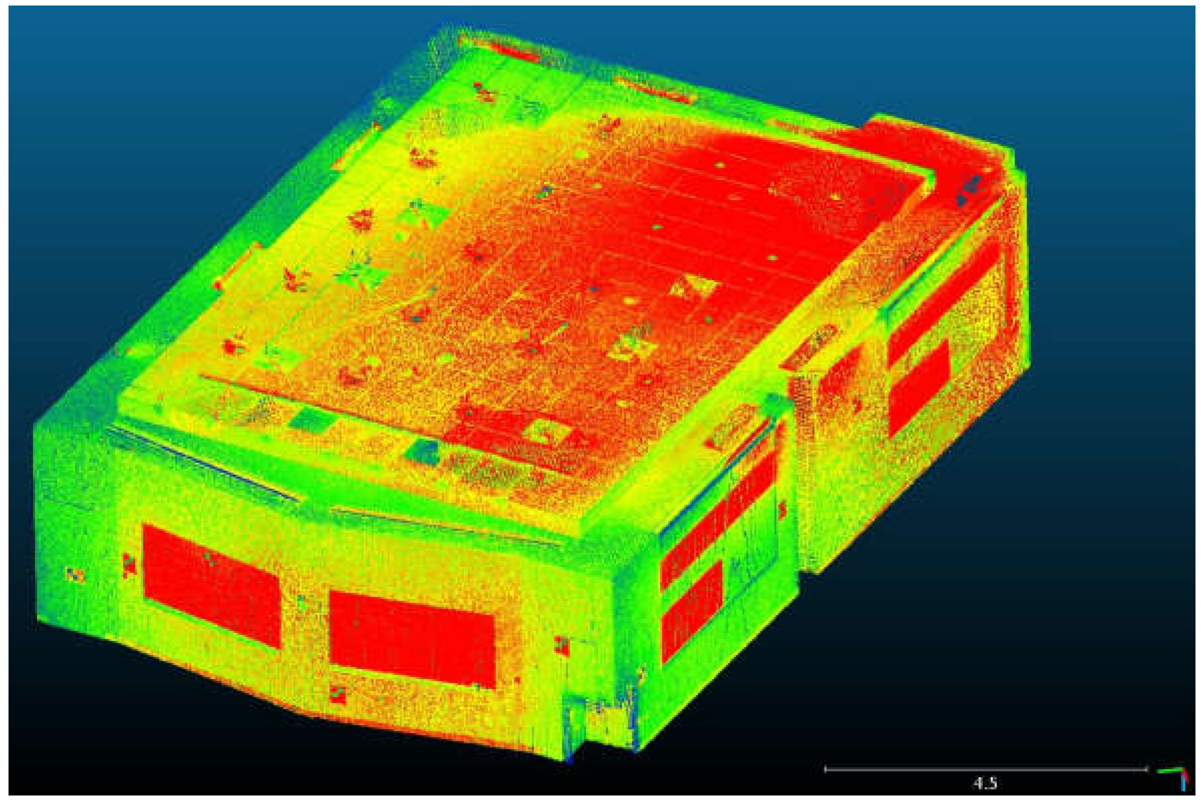
These data were used to study the Matterport Pro point cloud accuracy. FARO scanning was accomplished from four stations. The coordinate system was local. After the scans’ referencing in one model, the total size of the obtained model was over 40 million points (Figure 3).
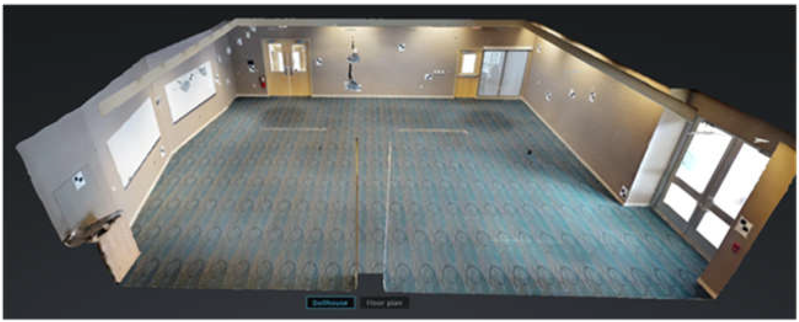
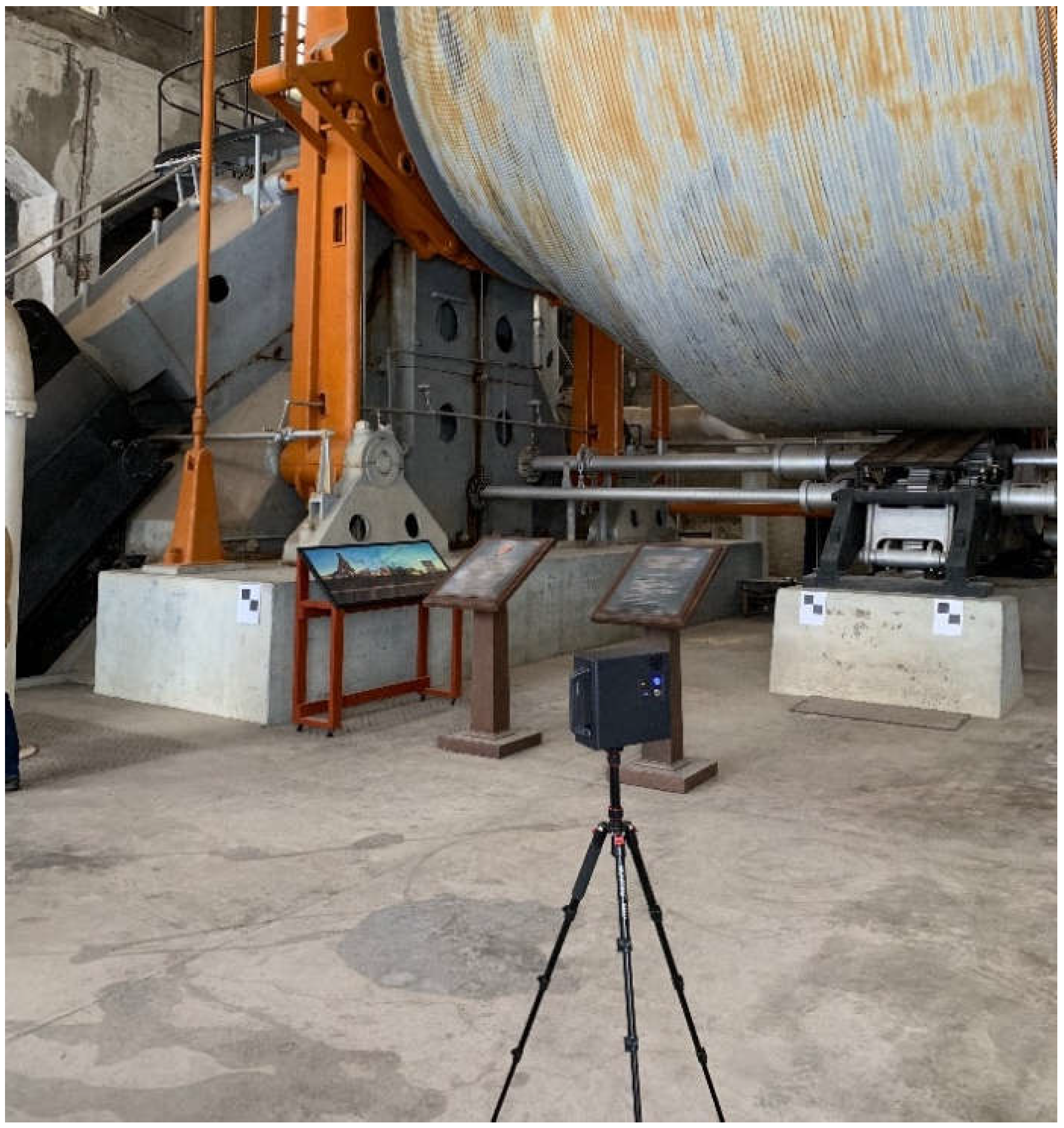
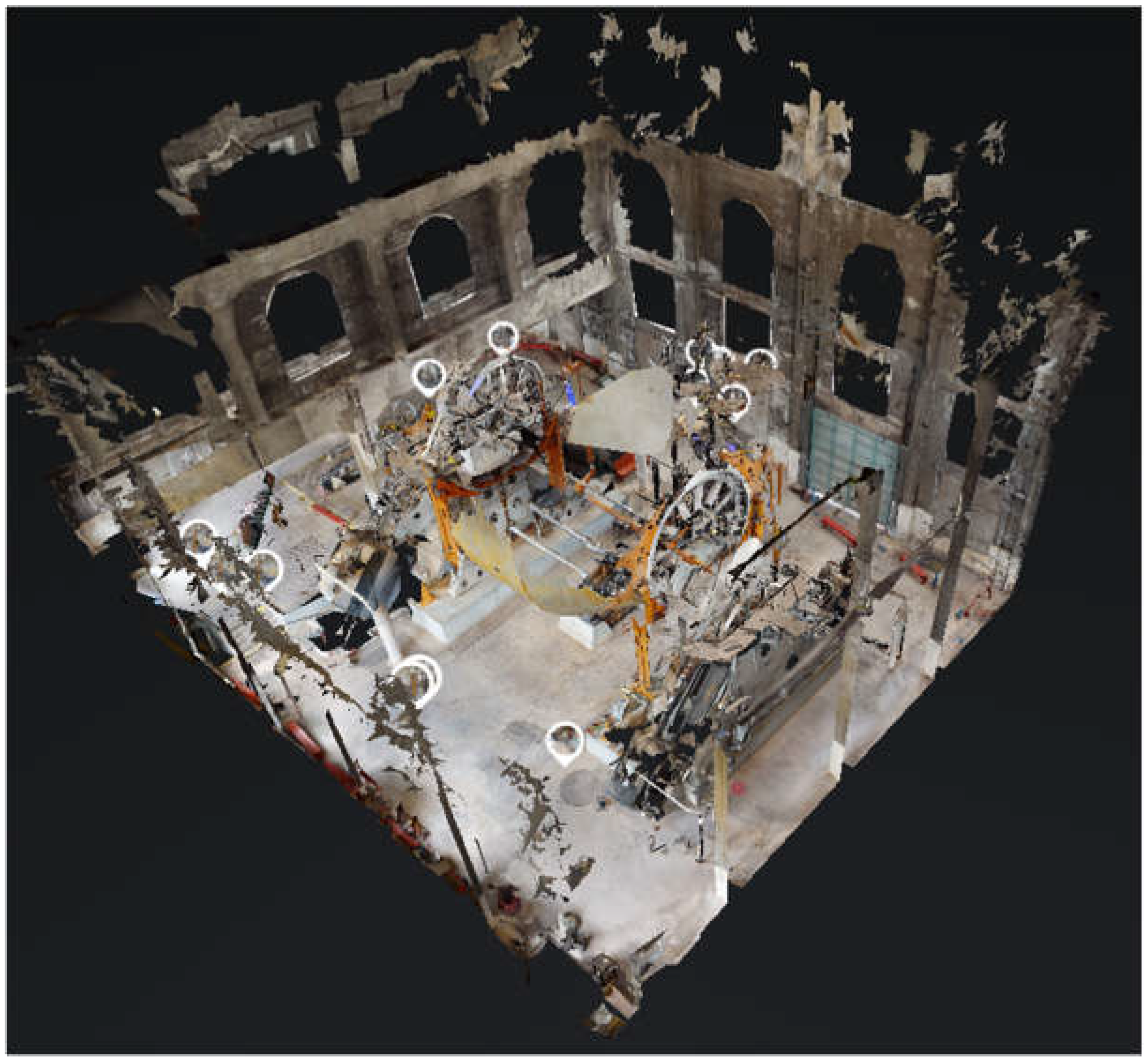
In the next step, Matterport Pro surveyed the same hall (Figure 4), and scanning results were forwarded to the Matterport company’s processing server (Figure 5). See Video S1: 3D Tour of Test Field in the Supplementary Materials section. Surveying was gained by Matterport Pro from eight stations with a model size of over 4 million points. It is essential to mention that Matterport Pro’s data capturing took just 10 min. These data were used for accuracy checks and revealing systematic errors.
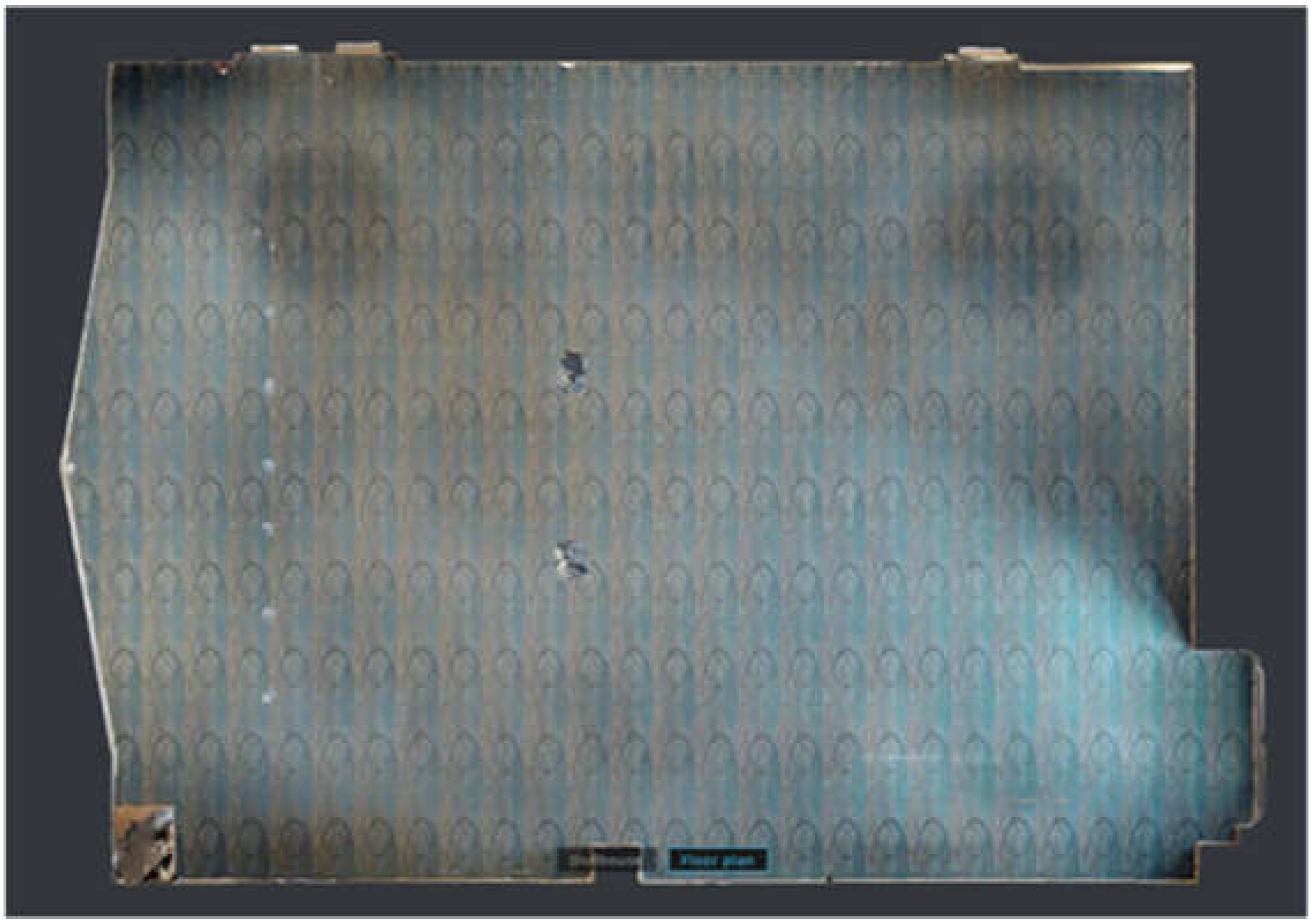
A three-dimensional point cloud and a horizontal plan (Figure 6) were generated as an output of the processing stage. The coordinates of the targets were measured on the point cloud.
The accuracy check is suggested to be carried out in two ways: (1) distance comparison and (2) cloud-to-cloud comparison. For the first approach, the distances between targets were used for the accuracy check insofar as the distances are invariant of the coordinate system. The distances were calculated using the well-known expressions:
d t s = Δ x t s 2 + Δ y t s 2 + Δ z t s 2 ;   d c a m = Δ x c a m 2 + Δ y c a m 2 + Δ z c a m 2 ,
where d t s is the total station distance and d c a m is the Matterport Pro distance. Based on the distances, the differences were calculated:
Δ d = d c a m d t s .
The obtained differences were used for further analysis. This approach works well when we deal with target coordinates. However, to estimate the point cloud accuracy, we need the TLS point cloud and the Matterport Pro point cloud and apply cloud-to-cloud comparison. The Iterative Closest Point (ICP) algorithm is a well-known approach for such a comparison. The procedure for the standard ICP is outlined in many sources, e.g., [44,45,46]. ICP was suggested and developed in 1992 by Besl and McKay [46]. This method has become the most popular method for the tasks of 3D modeling. The method has obtained increasing popularity in recent years and has many modifications. Here, we will use a standard ICP. The idea ICP is to orient two point clouds or 3D models to the fixed coordinate frame without reference data. The algorithm searches and references a pair of points in the different coordinate systems during each iteration. Once the pair has been defined, the algorithm determines transformation parameters to minimize the function [46]:
f R , t = i = 1 N m j = 1 N p w i j | | m i R s p i + t | | 2 ,
where N m , N p are numbers of points in clouds M and P R , s ,   t are rotation matrix, scale scalar or matrix, and shift vector between two coordinate systems; m i , p i are point vectors; and w i j values are the weights. From (3), we obtain the following:
f R , t = 1 N i = 1 N | | m i R s p i + t | | 2 .
where N = i = 1 N m j = 1 N p w i j .
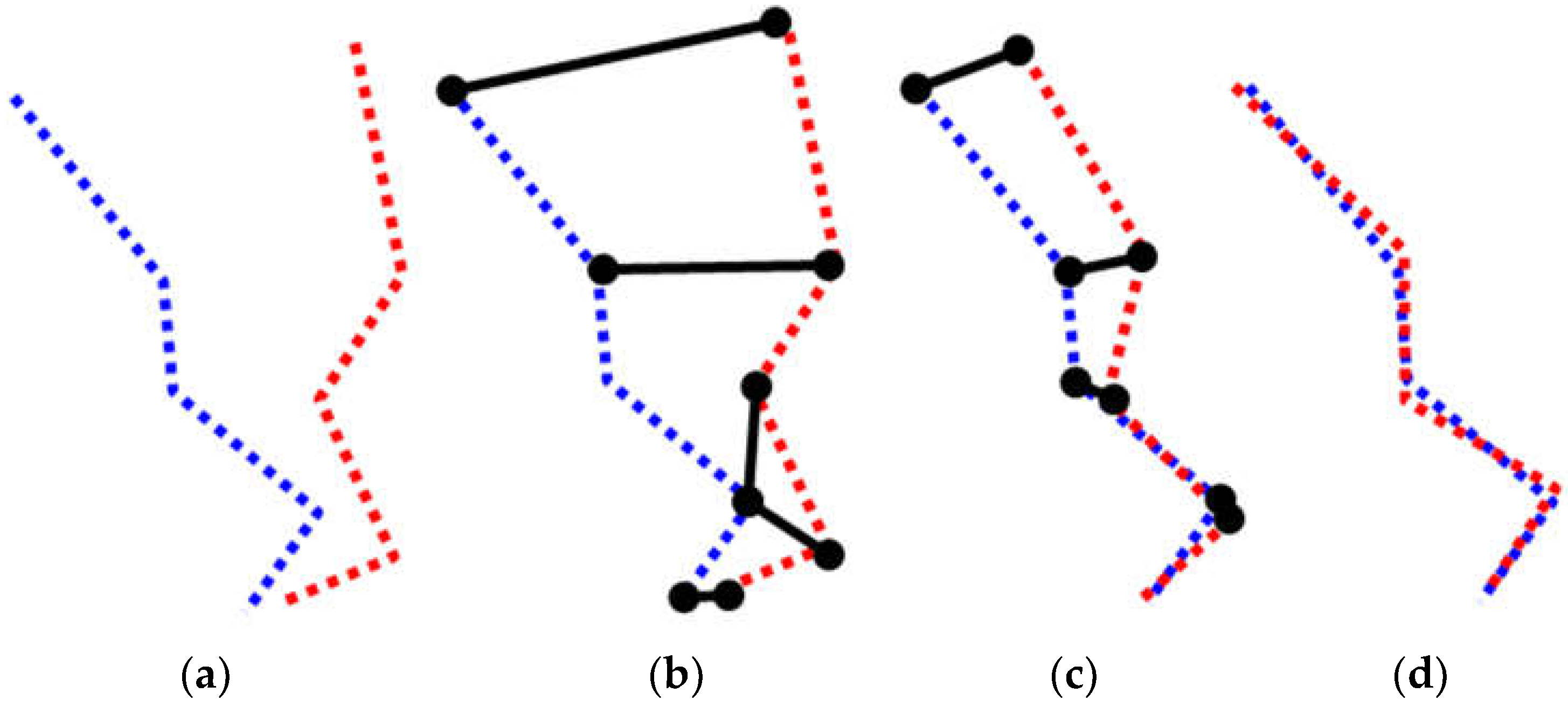
In the works [45,46], it is pointed out that ICP allows one to achieve the local minimum. The assignment of preliminary values of transformation parameters is a crucial condition to figure out the global minimum. This condition is easy to accomplish in our case. The idea of the ICP can be grasped from Figure 7.
This algorithm can also be treated as a kind of calibration, as far as the transformation of two clouds allows for the calculation of a scale parameter between these clouds.
However, a stricter approach for the calibration should be based on the target coordinates. In this case, the blunders in coordinates will not affect the accuracy of the parameters as far as they can be easily ruled out. For the 3D camera calibration, we suggest using the Helmert transformation in space. The general form of this transformation is as follows:
x y z t s = T x T y T z + 1 + d s x R z R y R z 1 + d s y R x R y R x 1 + d s z x y z c a m
where x t s , y t s , z t s are target coordinates in the total station coordinate system; x c a m , y c a m , z c a m are target coordinates in the Matterport coordinate system; T x , T y , T z are shifts of the coordinate systems; R x , R y , R z are rotation matrix coefficients; and d s x , d s y , d s z are scale coefficients.
This transformation allows for determining scale coefficients that can be used to correct the Matterport Pro data in what follows.
Therefore, a geometrical quality check will be established through two accuracy checks: distance comparison and cloud-to-cloud comparison. The calibration will be studied in cloud-to-cloud comparison and spatial Helmert transformation.

2.2. Study Object and Data for Modeling

It was mentioned that industrial archaeology comprises different engineering, social, and technological sciences to study the history and aftermath of past industrial activities [37]. As a multidisciplinary science, industrial archaeology examines miscellaneous objects. Among these are mechanisms and machines. The mining industry is an example of the application and dissemination of cutting-edge technologies, which is why the objects of the mining industry include different equipment that is the subject of industrial archaeology. On this basis, the Quincy Mine copper shaft, placed in the Upper Peninsula Michigan (Figure 8), was selected to study the Matterport Pro’s capabilities for industrial archaeology.
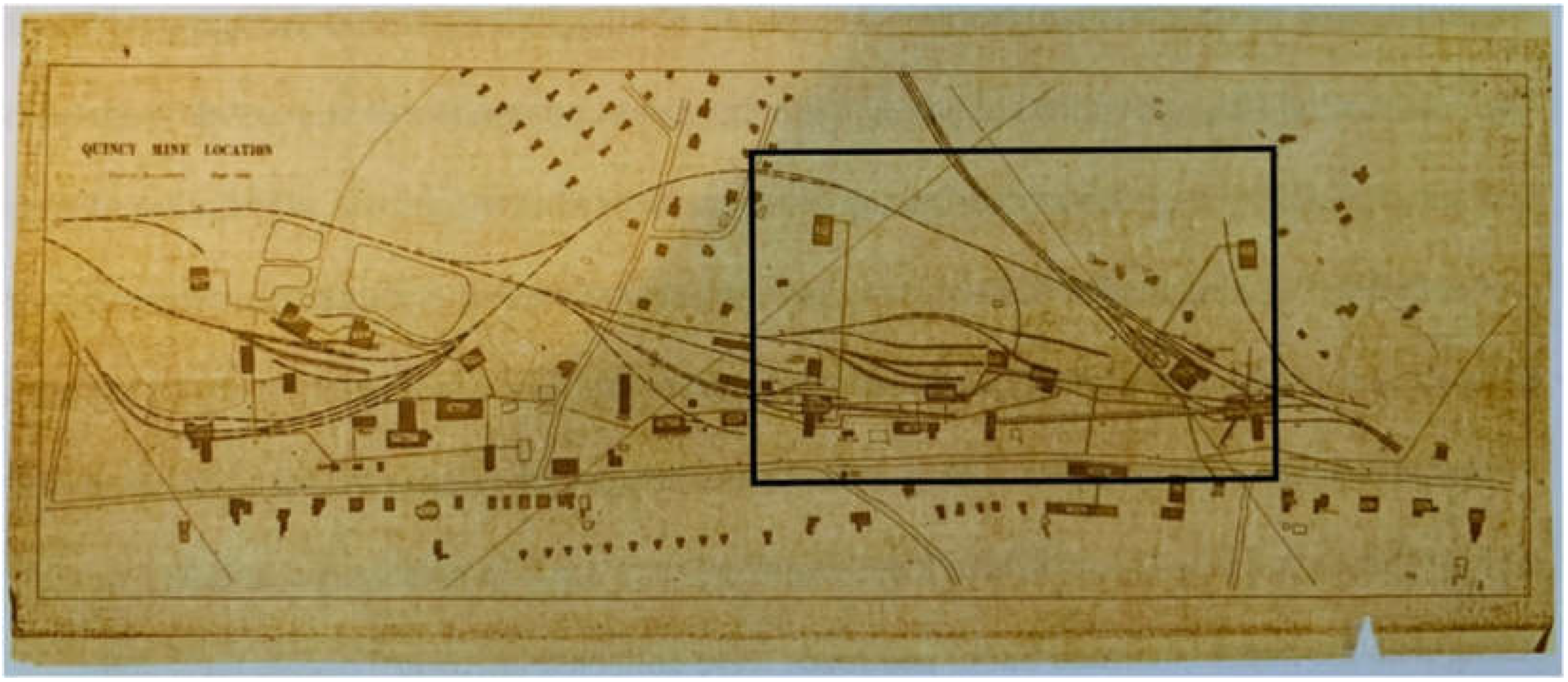
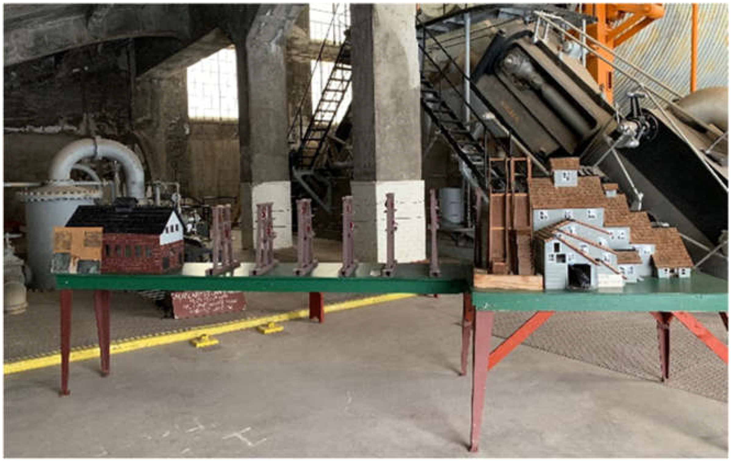
Upon the in-depth study of various archival materials at the Michigan Technological University library and discussions with members of the Quincy Mine Hoist Association, it was found that the Quincy Mine complex’s most attractive and exciting object is the Quincy Mine Hoist Engine. The Hoist Engine house is placed near Highway 41, Houghton, MI (Figure 8 and Figure 9).
The Quincy Mining Company (QMC) was established in 1846, with the main shaft at the Upper Peninsula Michigan. During the three years after 1859, the QMC evolved from a small shaft to a productive mining cluster. Extensive geological studies explored the large volumes of copper and silver ore. The company built the first complete plant in 1862, producing 2.1 million pounds of copper. The company grew from 1868 until 1920. The company’s personnel increased from 500 to 2000 people. The excavation power was 22 million pounds of copper yearly. During that time, the QMC technologies passed from a pre-mechanized to a highly mechanized era [40]. Yet the QMC had six shafts in operation at once. One of the largest massive steam-powered hoists in the world served these shafts—the Nordberg Steam Hoist [47] (Figure 10).
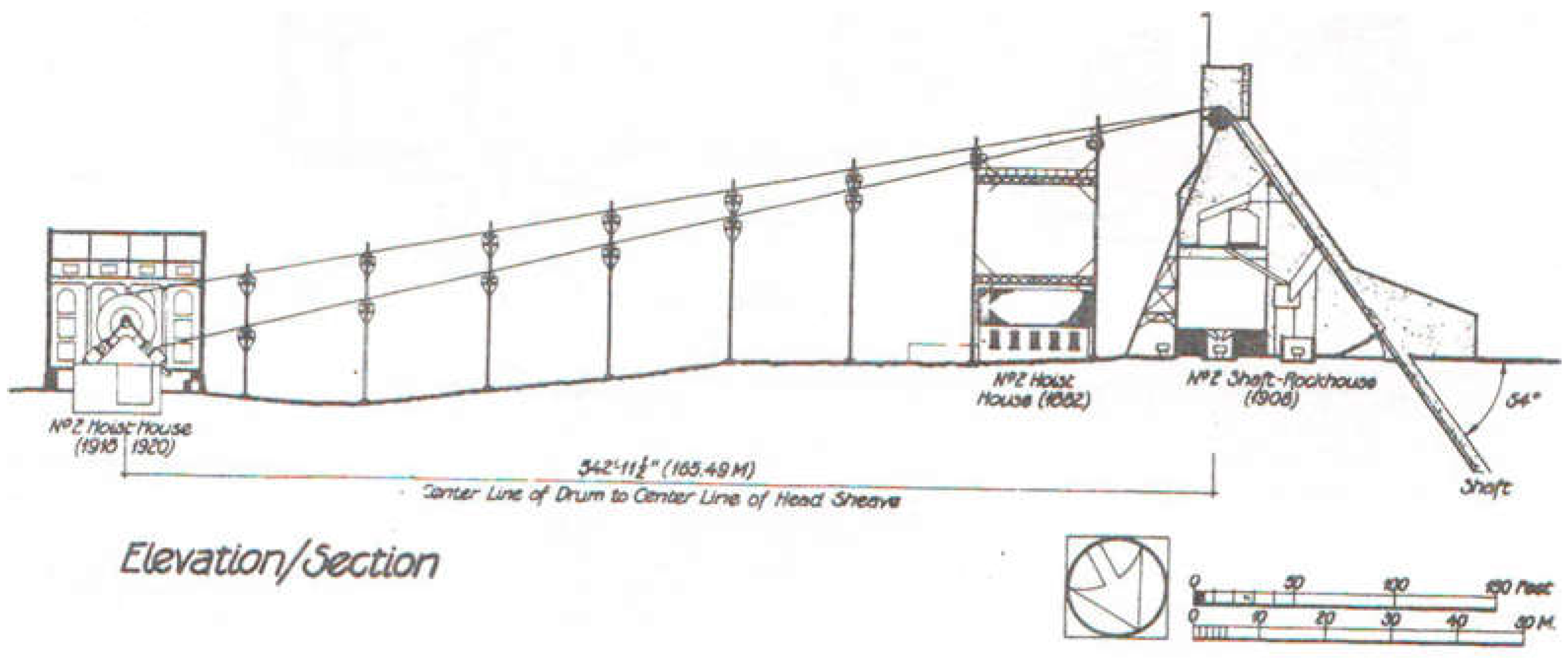
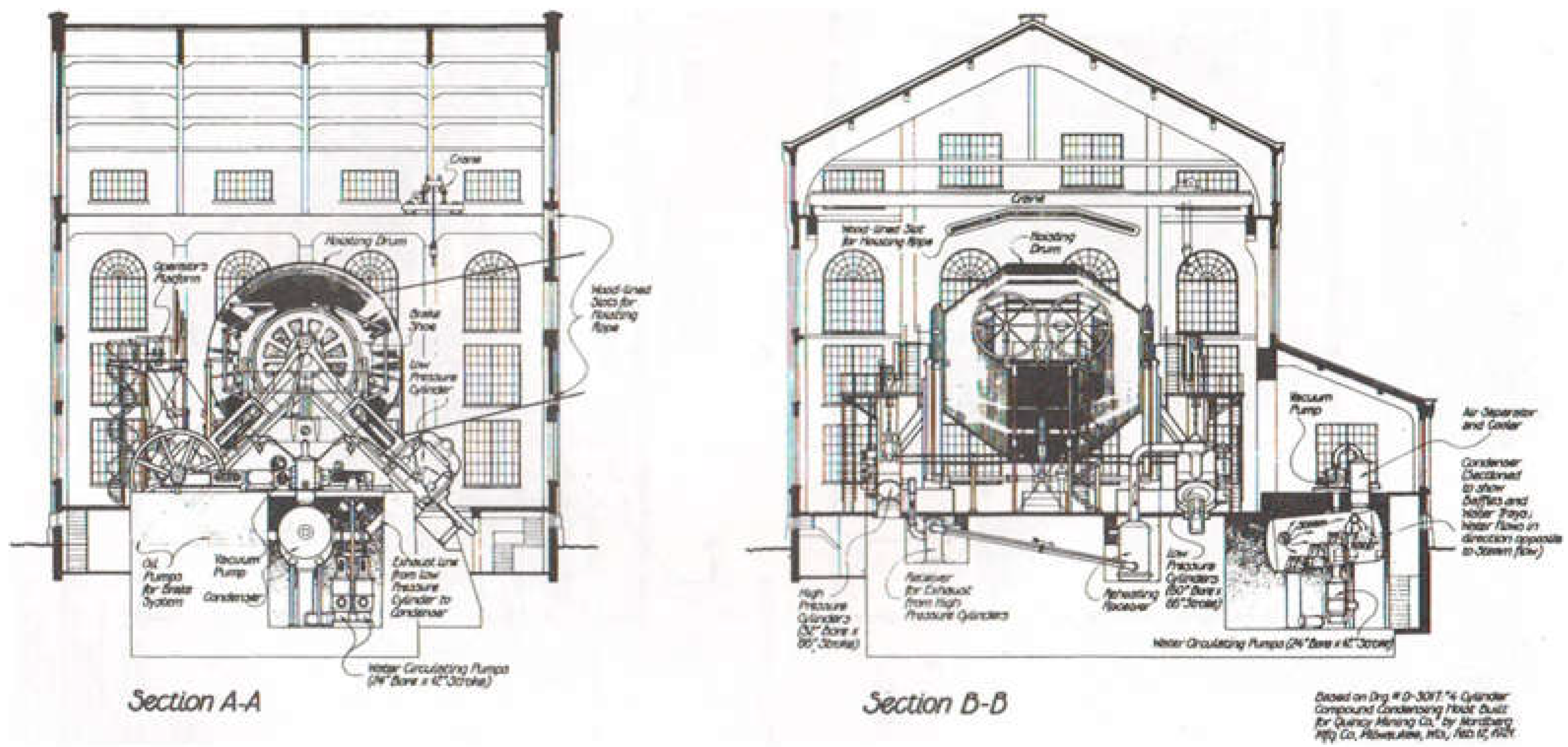
The Hoist Engine was placed in the house (Figure 11) 165 m from the shaft and provided the mining works.
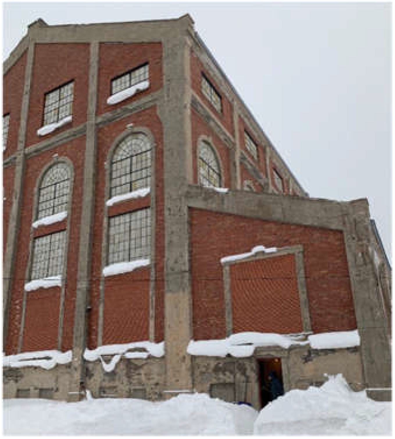
At that time, the maximum depth of the shaft reached 2 miles. The Nordberg Steam Hoist served 256 levels where copper was extracted. Nowadays, the view of the Hoist Engine house is presented in Figure 12.
The active history of the Quincy Mine ended in 1945 when the last mining was carried out and the shaft was shut down. However, that was the beginning of a new history. The whole complex of mining buildings and engines of the Quincy Mine (Figure 13) became an object of industrial archaeology and its studies. In 1978, the Historic American Engineering Record (HAER) enlisted the Quincy Mine as a significant engineering and industrial object in the U.S., emphasizing the role of the QMC and the equipment used there.
The Quincy Mine Hoist Association was established and declared its mission “to preserve, interpret, and educate the public about the history of copper mining in Michigan” [47]. The association deployed a museum dedicated to the QMC at the shaft territory and has conducted tourist tours throughout the shaft objects since then. The core object of these tours is the Nordberg Steam Hoist (Figure 14).
As mentioned in the introduction, one of the final outputs of the research was the support of the QMHA with a 3D model of the Quincy Mine Hoist Engine for a virtual tour [48]. Therefore, the Hoist Engine house and the Nordberg Steam Hoist were selected for the study. The data obtained by the outdoor and indoor surveying were finally gathered into one virtual model to ensure the virtual environment for virtual tours around the Quincy Mine Hoist Engine. The output of this modeling will be given in Section 3.

3. Results

3.1. Accuracy Check—Distance Comparison

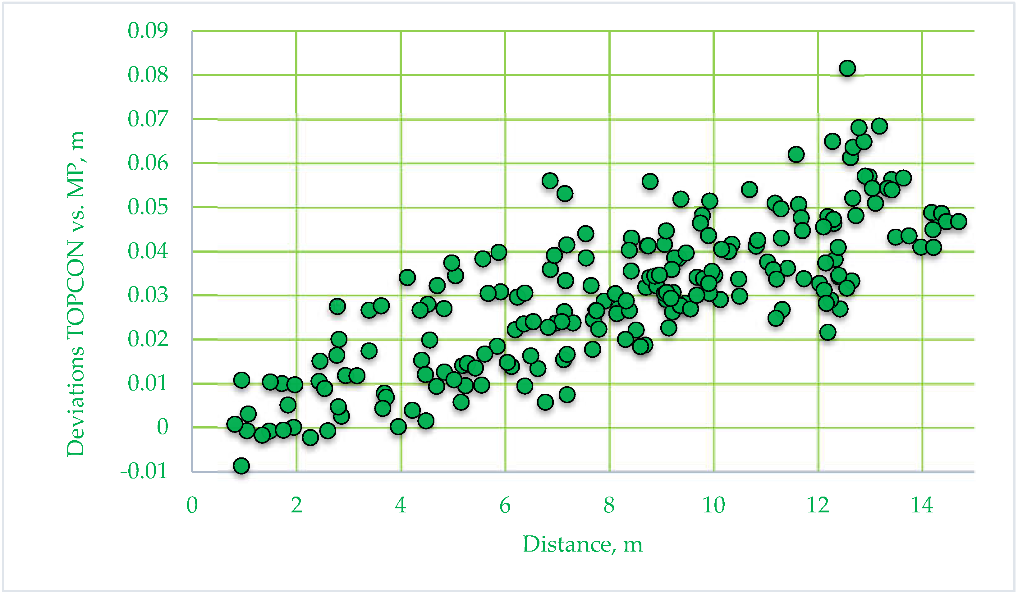
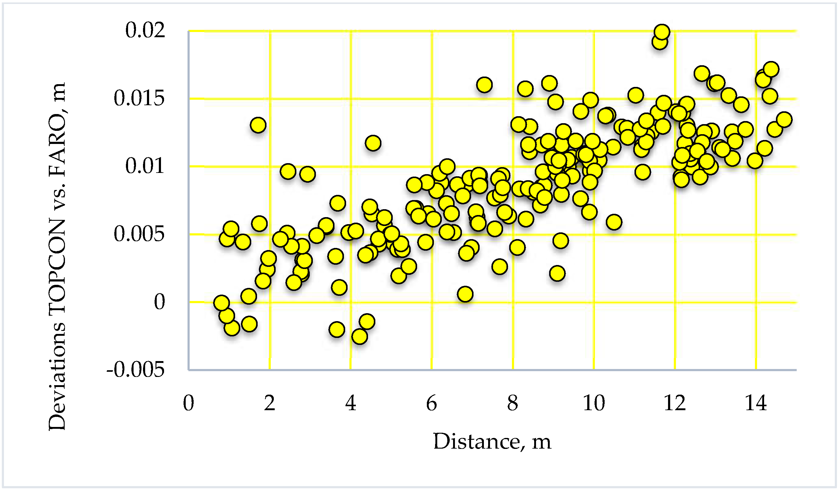
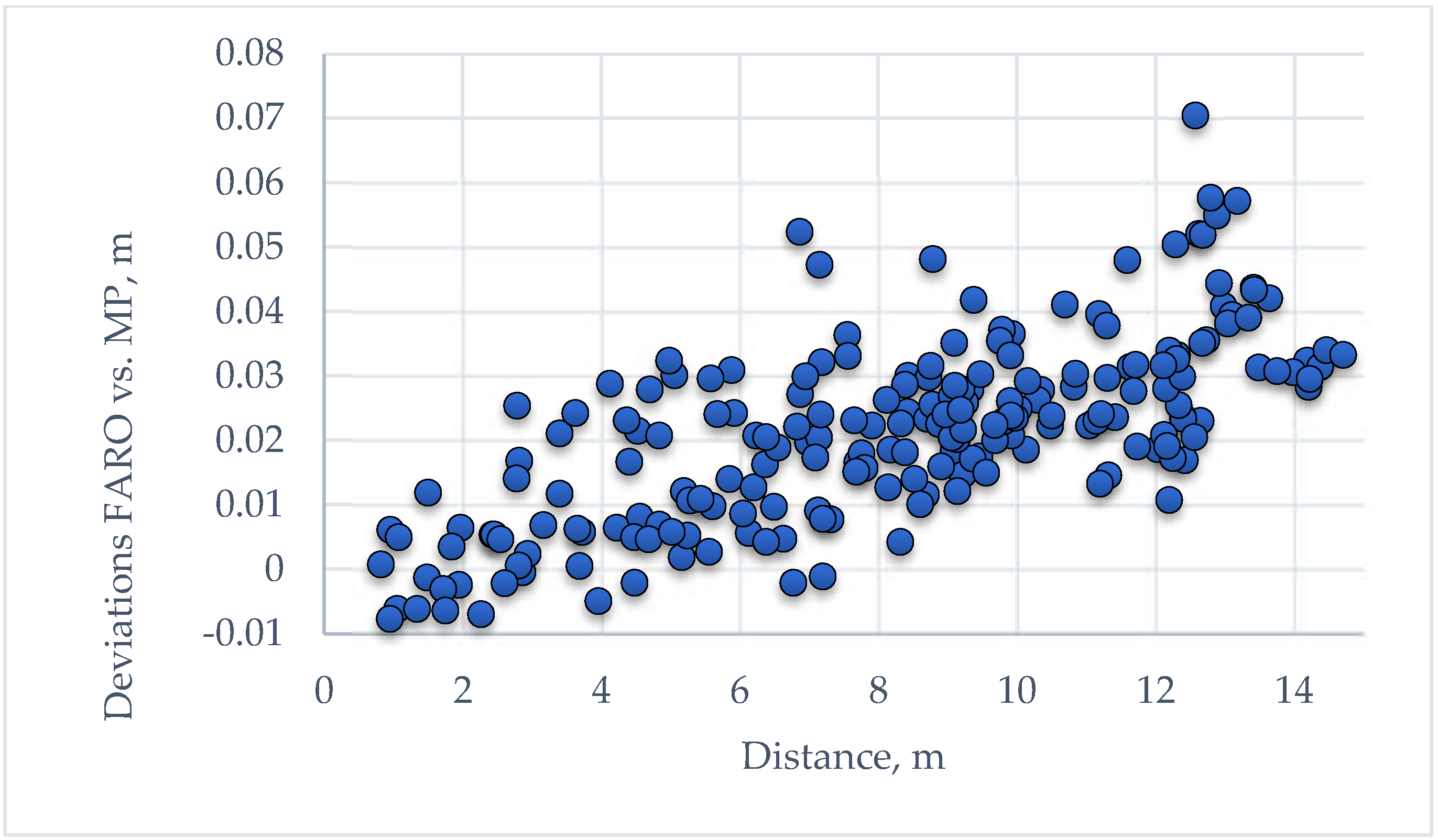
According to the procedures outlined in the previous section, the accuracy check is possible in two ways. The first approach is the distance comparison. To achieve this aim, three data sets were acquired. We have the target coordinates determined by the Topcon total station (TOPCON), measured on the Faro TLS point cloud (FARO), and measured on the Matterport 3D point cloud (MP). Therefore, we may determine three sets of differences: TOPCON vs. MP, TOPCON vs. FARO, and FARO vs. MP. In total, 210 distances were calculated using (1), and appropriate differences were determined using (2). If we consider one of the distance sets as a reference, we can treat the differences as deviations of one data set according to another. This premise is eligible as far as the total station measurements are many times more precise than other measurements, and of course, FARO measurements are more accurate than Matterport measurements. Thus, in what follows, we will consider deviations. These deviations are presented in Figure 15, Figure 16 and Figure 17.
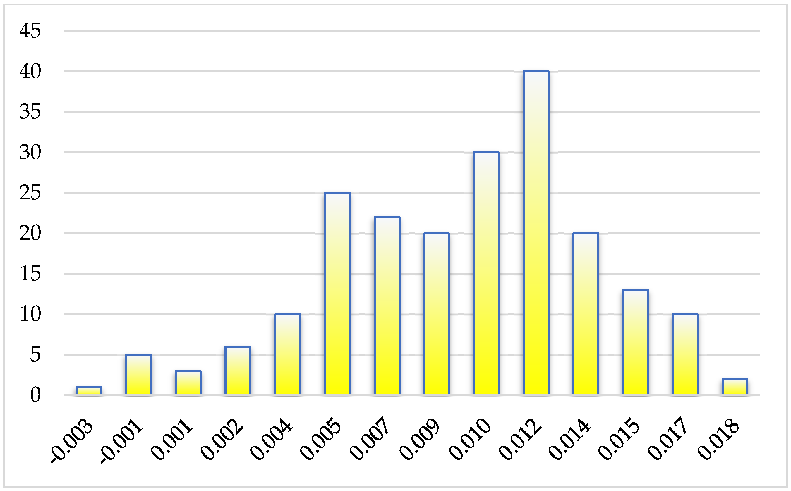
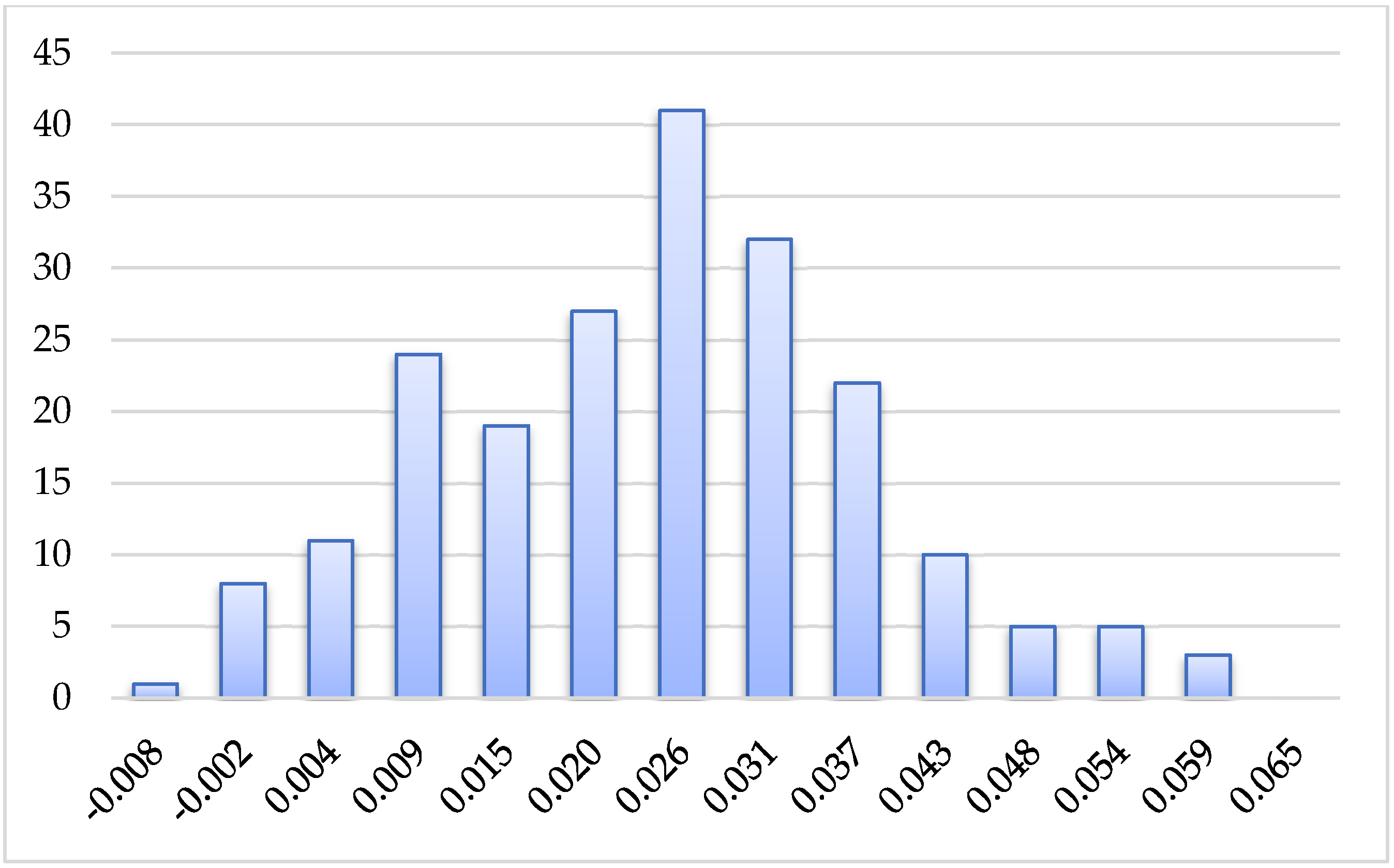
The appropriate histograms were generated to grasp the features of the presented distance deviations (Figure 18, Figure 19 and Figure 20).
Despite the slight deviations in the histograms (asymmetry), the obtained deviations obey a normal distribution but with a significant systematic shift. This shift is evident in the graphs in Figure 15, Figure 16 and Figure 17. The inferences regarding the yielded distance deviations are possible using descriptive statistics. The standard parameters of the descriptive statistics were calculated and are given in Table 1.
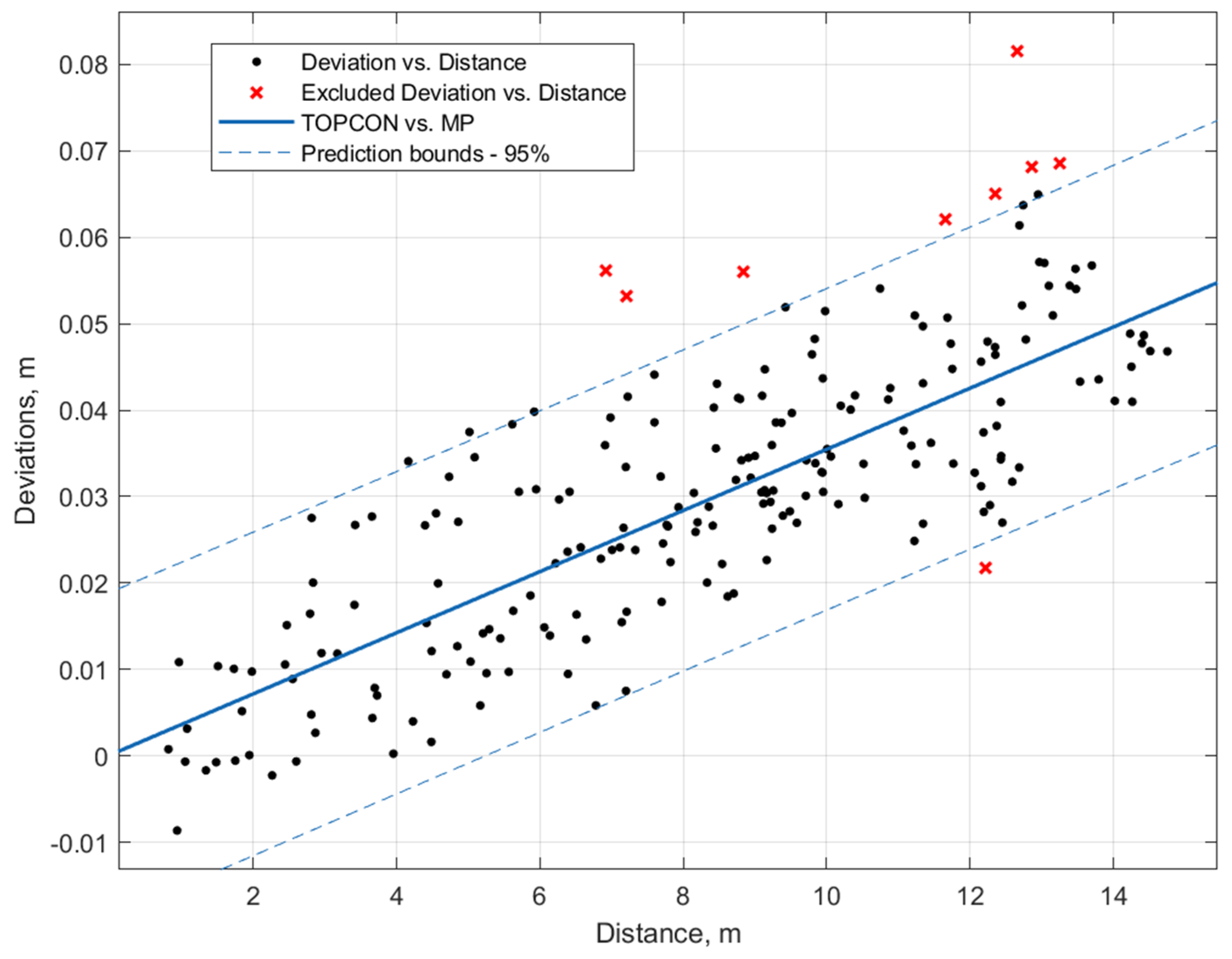
Since the longest distance does not exceed 12 m, the total station measurements are accepted as errorless. This assertion is eligible as far as the distance accuracy for the total station in reflectorless mode is ±2 mm. The accuracy of TLS is approximately on the same level. However, due to minor errors in the targets’ center determination on the point cloud, the TLS is supposed to be less accurate than the total station. Under this precondition, let us analyze the figures in Table 1. First, the accuracy of the total station and TLS is compatible. This means that in what follows, we may use the TLS point cloud as a reference for cloud-to-cloud comparison. Second, the root mean square errors for Matterport regarding the total station and TLS are statistically similar at 14 mm and 16.6 mm, respectively. If we accept the mean measured distance of 8.3 m, then relative distance accuracy equals 1:600 and 1:500 or 0.17% and 0.2%. These results are much better than the accuracy for Matterport declared by the manufacturer (1%). However, the distances are relatively short, and after sorting the deviations by distance length in ascending order, it was found that deviations have a clear systematic trend. The disparities grow with length. The histograms (Figure 18 and Figure 20) also clarify the systematic trend. The following analysis will be based on the deviations between the total station and Matterport. Systematic errors distort the distances, as we may infer from Figure 15 and Figure 17. Almost all the deviations have positive values with a central meaning near 0.03 m. Such a value exceeds the measurement accuracy considerably. The simple analysis has shown that the measured values from the 3D camera must be corrected for a scale factor of nearly 1.004. This result pushed the thought that the 3D camera distances are distorted by linear components depending on the distance length. A simple polynomial approximation was used to deal with both of these components. As a basic equation, the following expression was considered:
f = p 0 + p 1 d + p 2 d 2 + .
where p 0 , p 1 , p 2 are polynomial coefficients.
In expression (6), it is more than enough to account for the first two coefficients. Therefore, a simple linear model was constructed. The following parameters present the linear model with a 95% confidence level: p0 = −4.606 × 10⁻⁵, confidence interval (0.003531, 0.003439); p1 = 0.003624, confidence interval (0.003238, 0.00401); adjusted R-square = 0.62; RMS error = 0.0102 m. Figure 21 shows that some differences may be treated as outliers. After the elimination of these blunders, the model was refined, and the following parameters and their estimations were obtained with a 95% confidence level: p0 = 0.0001, confidence interval (−0.00318, 0.00333); p1 = 0.003537, confidence interval (0.00318, 0.0039); adjusted R-square = 0.63; RMS error = 0.0094 m. The coefficient of determination R-squared has a reliable value, and the polynomial coefficients are in the bounds of the interval for a 95% confidence level. However, only the first coefficient must be considered practically significant. The correction equation is
f = 0.003537 d .
Expression (7) is used to calculate the corrected deviations for the 3D camera distances. After applying the scale factor, the distribution of the differences changed significantly (see Figure 22). The deviations are scattered randomly, and there is no recognizable dependency between these deviations and distance length. Yet a systematic shift still moves the deviations slightly towards negative values.
The root mean square error for the measured distances was 9.4 mm. If we accept the previous mean measured distance of 8.3 m, then, in effect, the relative distance accuracy equals 1:880 or 0.11%. Of course, this result looks overly optimistic, and probably, for longer distances, the distortions will be different. Thus, the checking procedure confirmed the existence of the scale systematic error in the Matterport data. But this scale error cannot be suggested as a scaling coefficient as far as it is applied for distances, not coordinates. Thus, the scale error states the fact of systematic errors but is useless for data correction. Furthermore, since this scale error is bound to the coordinates of the scanty set of particular targets, it is worth determining the systematic error and accounting for the whole point cloud.

3.2. Accuracy Check—Clouds Comparison

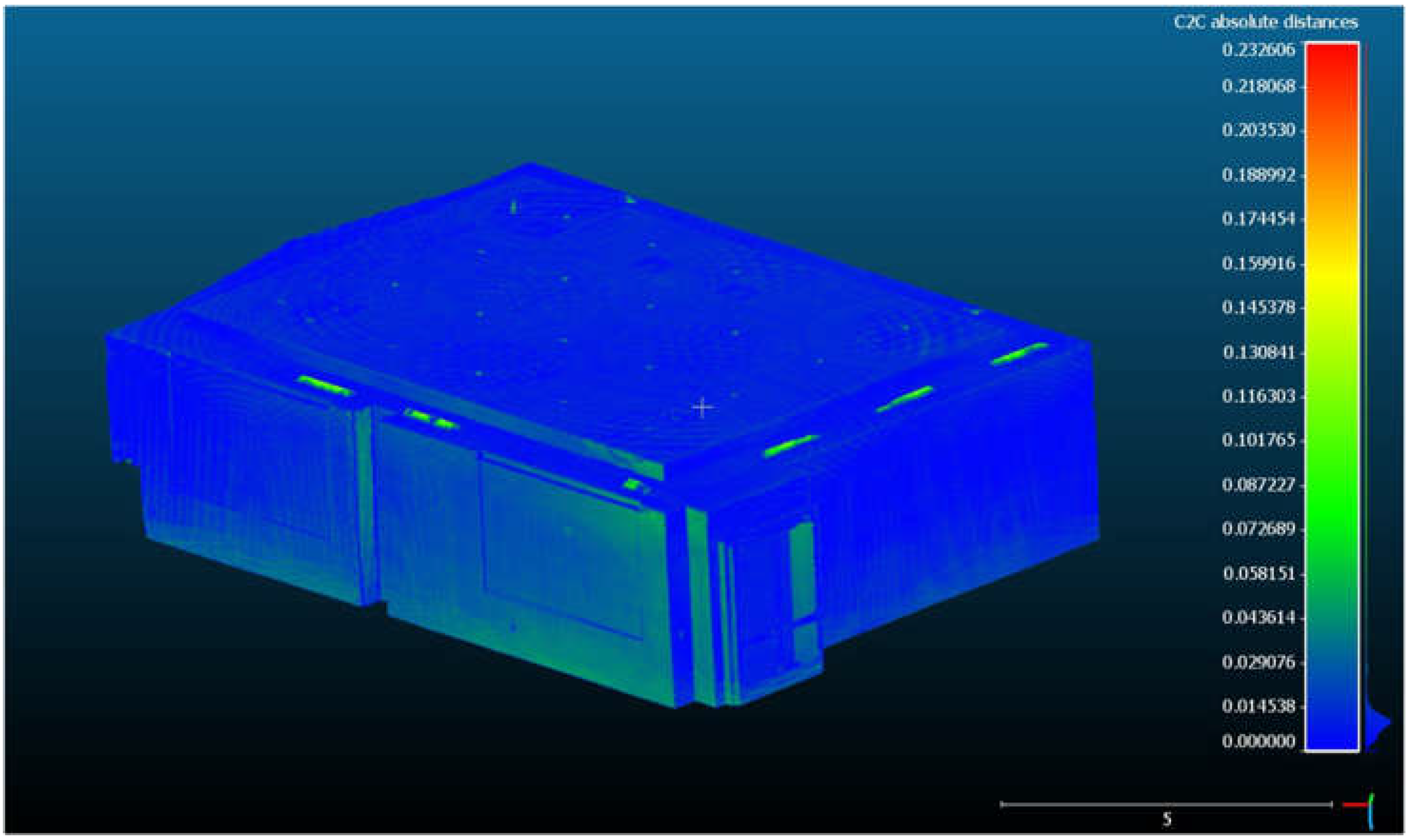
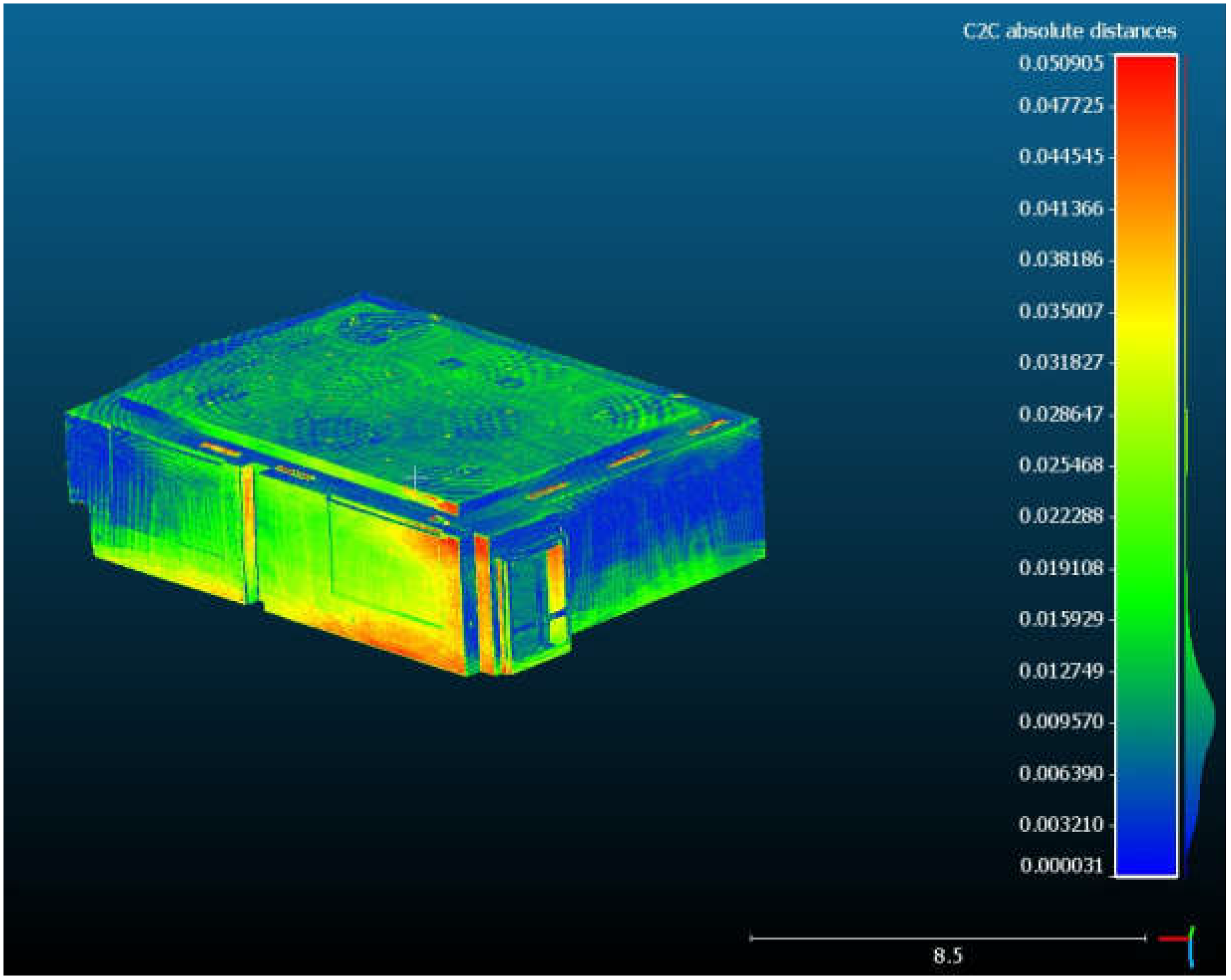
The cloud-to-cloud comparison will be denoted as C2C. For this comparison, two point clouds were used. FARO point cloud was assigned as a reference cloud. FARO point cloud was compared with the Matterport-generated point cloud (MP). The comparison of these clouds was accomplished using CloudCompare software (Version 2.12.4). To obtain reliable results, we need to reconcile these two clouds. The FARO point cloud was almost ten times bigger than the MP cloud. So the FARO point cloud was decimated to reduce the cloud size to 4M points. The FARO cloud was downsampled evenly to obtain a cloud of approximately the same size with a similar resolution. The first ICP transformation has been accomplished using default parameters (Figure 23).
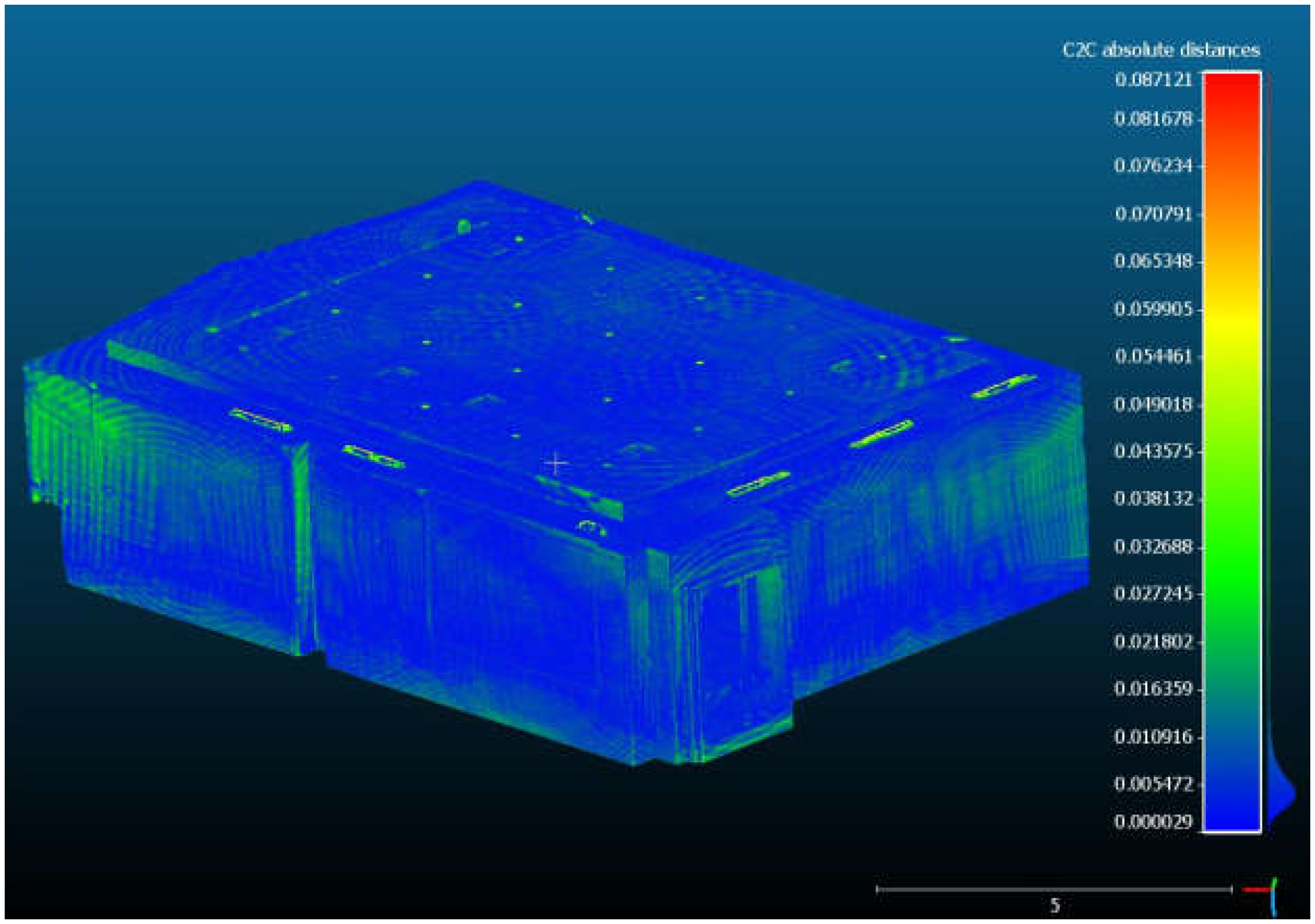
In Figure 23, the effect of blunders is significant. Therefore, before the analysis, both clouds should be cleaned from the blunders. The simple filter that restricts the difference values was applied. After employing the filter, the difference values look similar to the distance comparison in Section 3.1 (see absolute distances scale in Figure 24).
Now, it is possible to embark on the refined ICP transformation and further C2C distance calculation. Due to the vast redundancy of point clouds, we decided to study the effect of point cloud size on the ICP transformation results. The results are outlined in Table 2.
In Table 2, we have five sizes of point clouds. For each size, the ICP orientation without scale coefficient has been accomplished (three shifts and three rotations were determined). The distances between the two clouds after the orientation were calculated. These distances are deviations between two clouds, and the mean value and RMS error describe their distribution. The mean value and RMS error are reduced as the cloud size gets smaller. However, on the other hand, the orientation RMS error grows and finally becomes two times bigger than for the original cloud orientation. This proves that the redundancy of the original cloud provides reliable results, and it is not recommended to downsample the original Matterport point cloud. Secondly, the ICP orientation with the scale coefficient was carried out. The orientation RMS error equals ±7 mm for the original point cloud. C2C comparison showed an RMS error of ±4 mm, which is equivalent to the accuracy of the FARO point cloud. The results can be considered reliable. The scale coefficient 1.003381 is close to the scale coefficient according to distance-to-distance comparison 1.003537. Despite some differences deviating significantly from the mean value, the overall picture shows admissible deviations for the whole test field (Figure 25).
Therefore, we may use the scale coefficient to correct the Matterport point cloud to obtain an undistorted point cloud. However, as in the previous case, the scale coefficient scales point coordinates similarly. Such a scale coefficient does not account for the condition for which the distortions will differ along different coordinate axes. Therefore, calibration is mandatory.

3.3. Calibration

The reliable determination of the scale error is a subject of calibration. Insofar as we stress the primary attention on the scale error, applying a 3D Helmert transformation with three scale coefficients was suggested to draw out the scale errors. The coordinates of target points in both local coordinate systems (total station and Matterport) were used for the transformation. The transformation parameters were found using the program JAG3D [49]. The transformation parameters and their accuracy estimation are presented in Table 3.
Among the various parameters in Table 3 of interest are scale coefficients d s x , d s y , d s z . These scale coefficients present the systematic distortion of the Matterport point cloud along the coordinate axes. The scale along the z-axis is insignificant and can be neglected in what follows. This fact is proved by hypothesis testing in the rightmost column in Table 3. The coordinates, coordinate accuracy, and coordinate deviations on targets are given in Table 4.
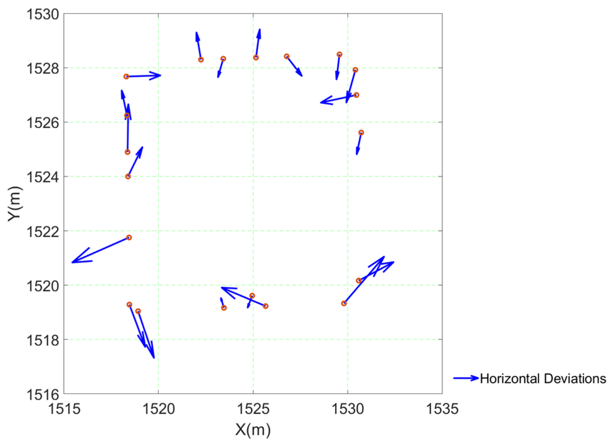
The deviations in Table 4 are the resultant of transformation and describe the accuracy after conversion. The deviation vectors in the horizontal plane are presented in Figure 26, whereas the spatial deviations are in Figure 27.
Figure 26 and Figure 27 exhibit a random distribution for deviations at the targets after the coordinate transformation. Thus, some of the systematic errors were ruled out from the data. Then, we may recommend using the scale coefficients d s x = 1.003268 and d s y = 1.003899 as calibration parameters given in Table 3 to correct the coordinates of the Matterport point cloud. Surveying a historical industrial object was accomplished to prove the accepted premise, and the scale coefficients obtained above were applied to correct the 3D model of the historical object.

3.4. Quincy Mine Hoist Engine: Outdoor and Indoor Surveying and Modeling

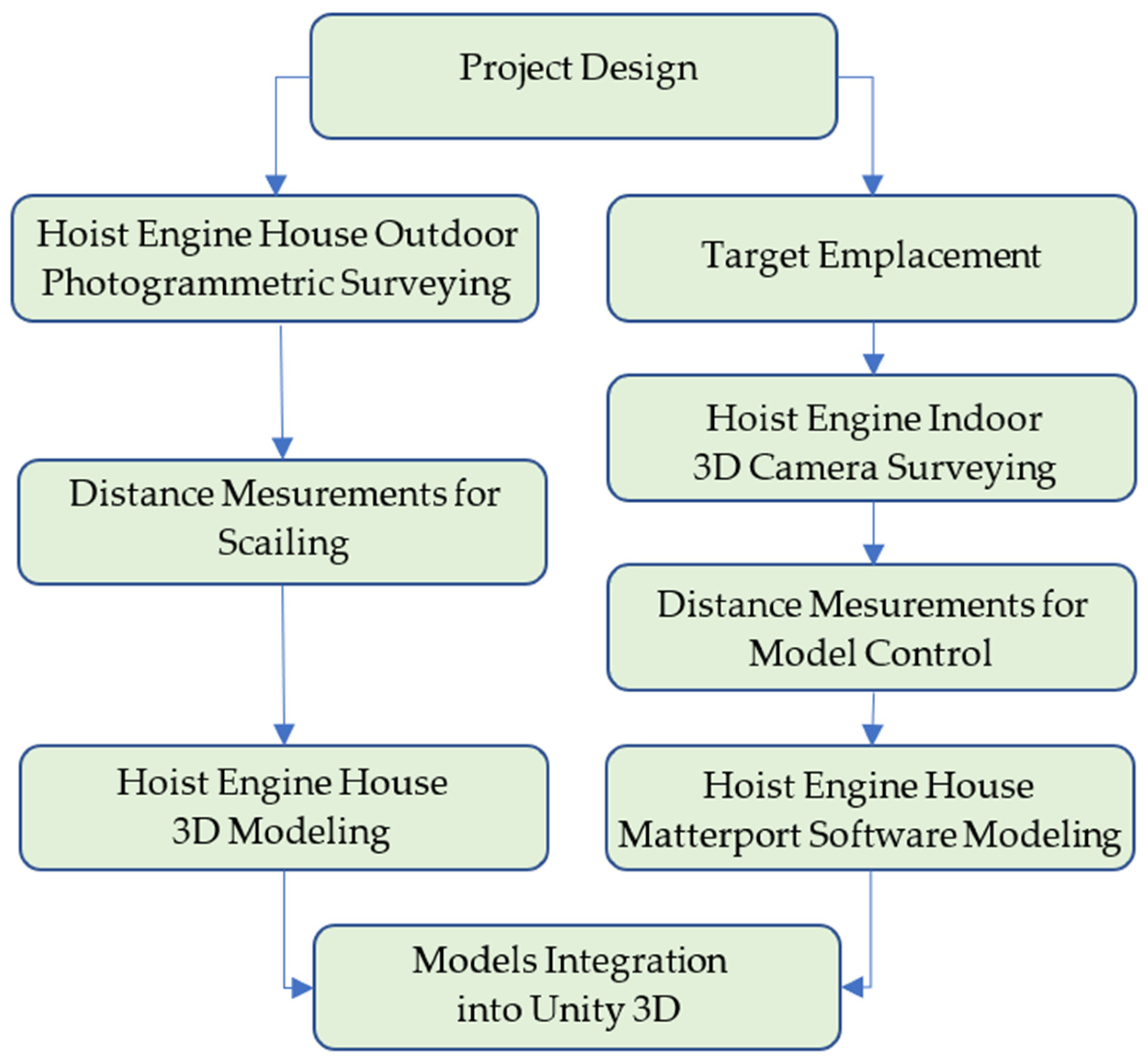
The whole process of outdoor and indoor surveying and modeling is presented in Figure 28.
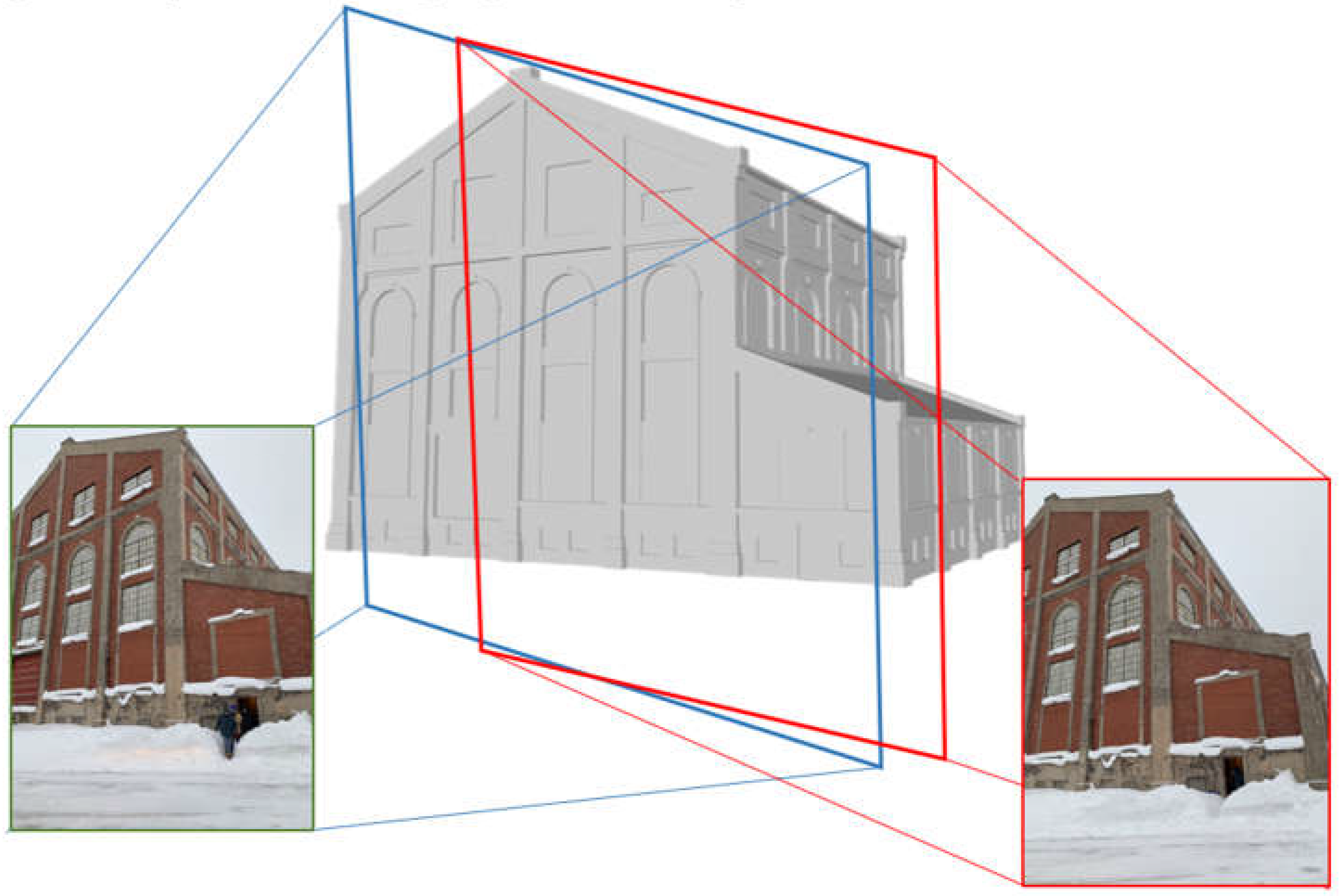
The data-acquisition process can be divided into two steps. In the first step, a low-cost digital camera gathered data for the Hoist Engine house 3D model (Figure 29). The photogrammetric processing procedure for the house modeling was conventional, and images were processed using Agisoft Metashape software (Version 1.7.2).
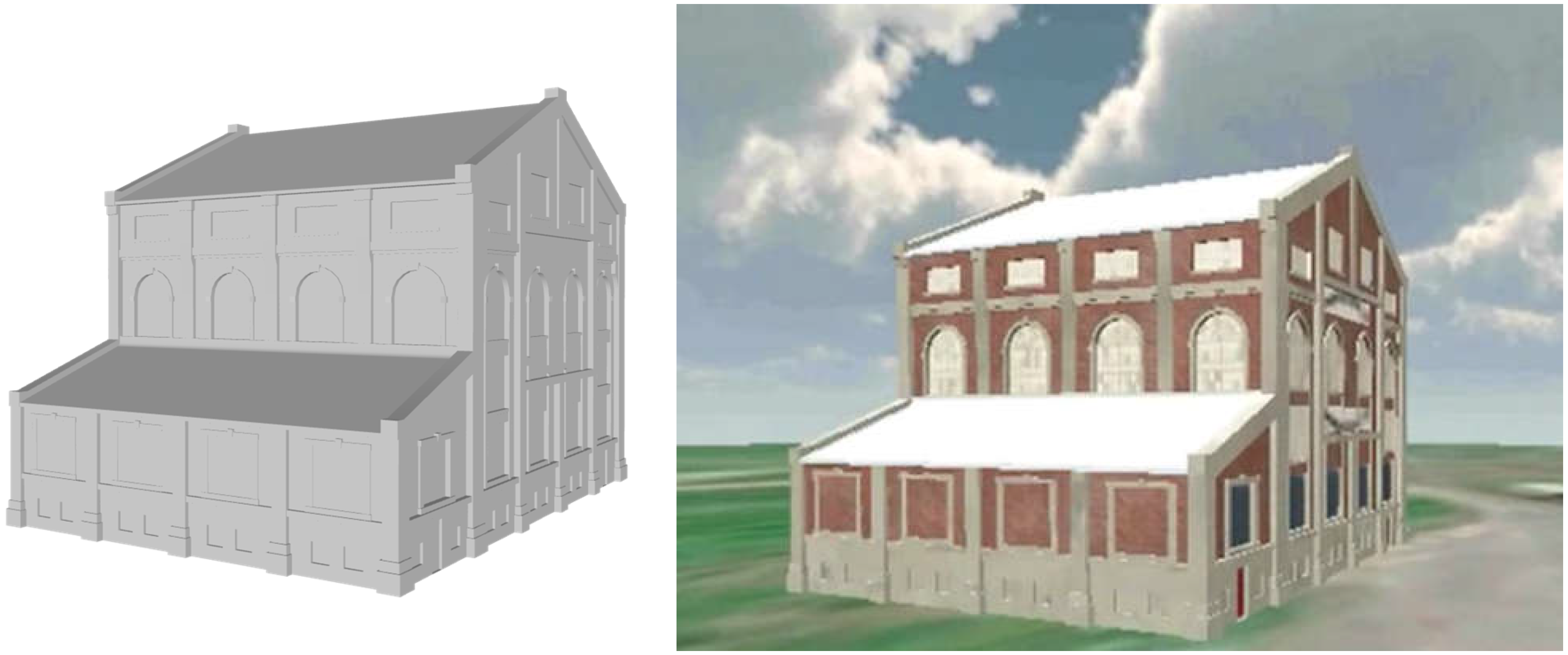
The results of the modeling are necessary for further virtual model creation. The Hoist Engine house model was converted to a 3D obj file. The model in this file was textured and referenced to the satellite imagery (Figure 30).
The second step was the data acquisition of the house’s indoor environment by Matterport Pro (Figure 31). It is worth mentioning the large size of the Nordberg Steam Hoist. The engine’s height is over 12 m, and to overcome this issue, surveying was performed from the surrounding platforms. Simultaneously, the Matterport Pro’s performance was tested for adverse weather conditions. During data capturing, the temperature was below −10 °C. However, Matterport Pro managed these critical conditions pretty well.
Some images captured by Matterport Pro and exported to the Matterport software (Version 770.22031) are portrayed in Figure 32.
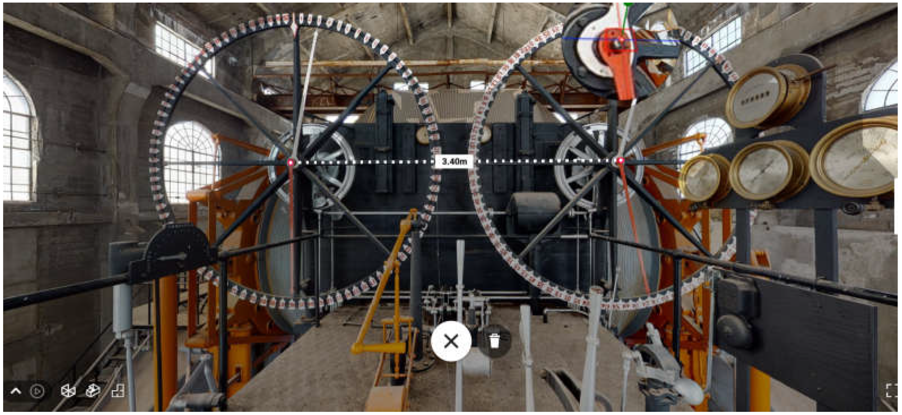
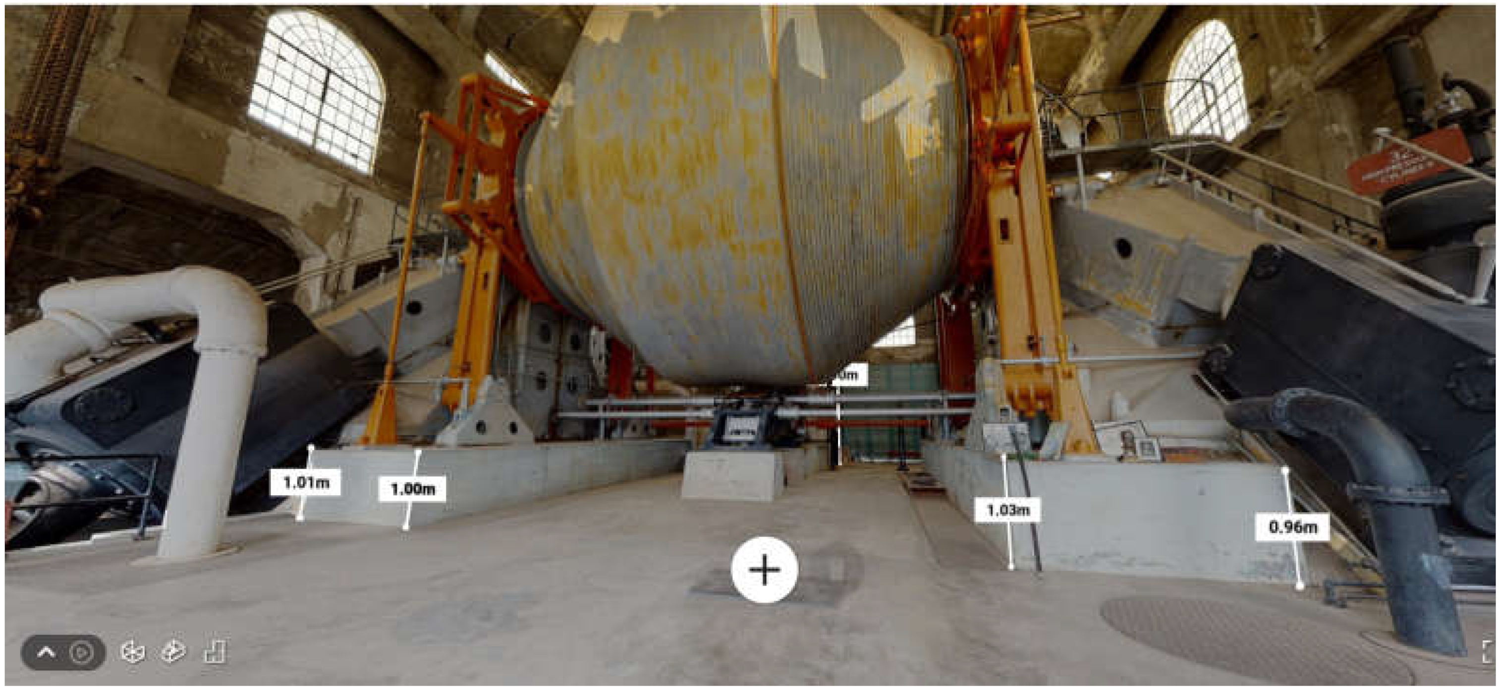
The surveying was accomplished on the ground, from ladders and platforms around the Hoist Engine. The total size of the point cloud obtained from 56 stations is almost 49 million points. The surveying time did not exceed 1 h, which demonstrates the high capability of the Matterport Pro camera for surveying such complex industrial objects. The data were sent to the Matterport processing server. Matterport processing software provides powerful tools for visualization, measurements, drawings, and point cloud generation. A screenshot of the whole data set is shown in Figure 33.
A video that presents the overview of the data set is provided via the Supplementary Materials section (Video S2: Short Introduction QM). Figure 34, Figure 35 and Figure 36 present the measurement option in the Matterport software.
Finally, the rendered 3D model of the Quincy Mine Hoist Engine house was generated. Video S3: 3D Trip Around Hoist Engine, from Supplementary Materials, demonstrates how any user can walk around the object, step up on its top, and carry out the required measurements. Moreover, the obtained 3D model was embedded into the house photogrammetric model, which, in turn, was placed on the georeferenced satellite imagery. A demo of the whole tour from the space to the indoor view was released using Unity3D software (Version 1.5). As a result, any user can open up the application on a PC, walk around the house, look in the Hoist Engine house, and even make distance and coordinate measurements inside the house. In the Supplementary Materials section, the sample case of how this can be carried out is given in Video S4: QM VR Unity3D. As mentioned, the Matterport software allows for generating the colorized point cloud. Such a point cloud may be used for various virtual applications and precise measurements. This option is essential for industrial archaeology, where the dimensions of the objects must be determined accurately. The geometric quality of the Quincy Mine Hoist Engine model was checked. These results are presented in Section 4.

4. Discussion

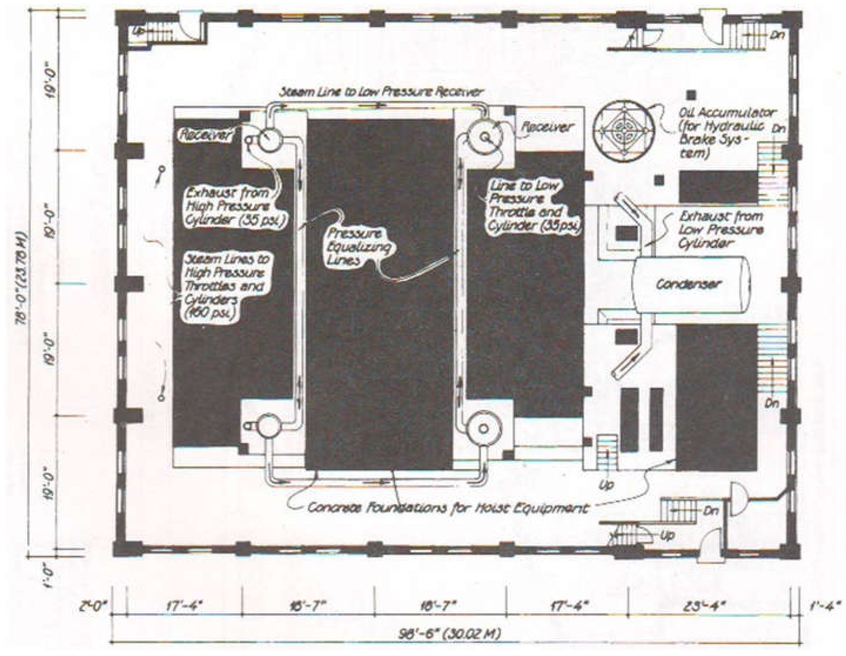
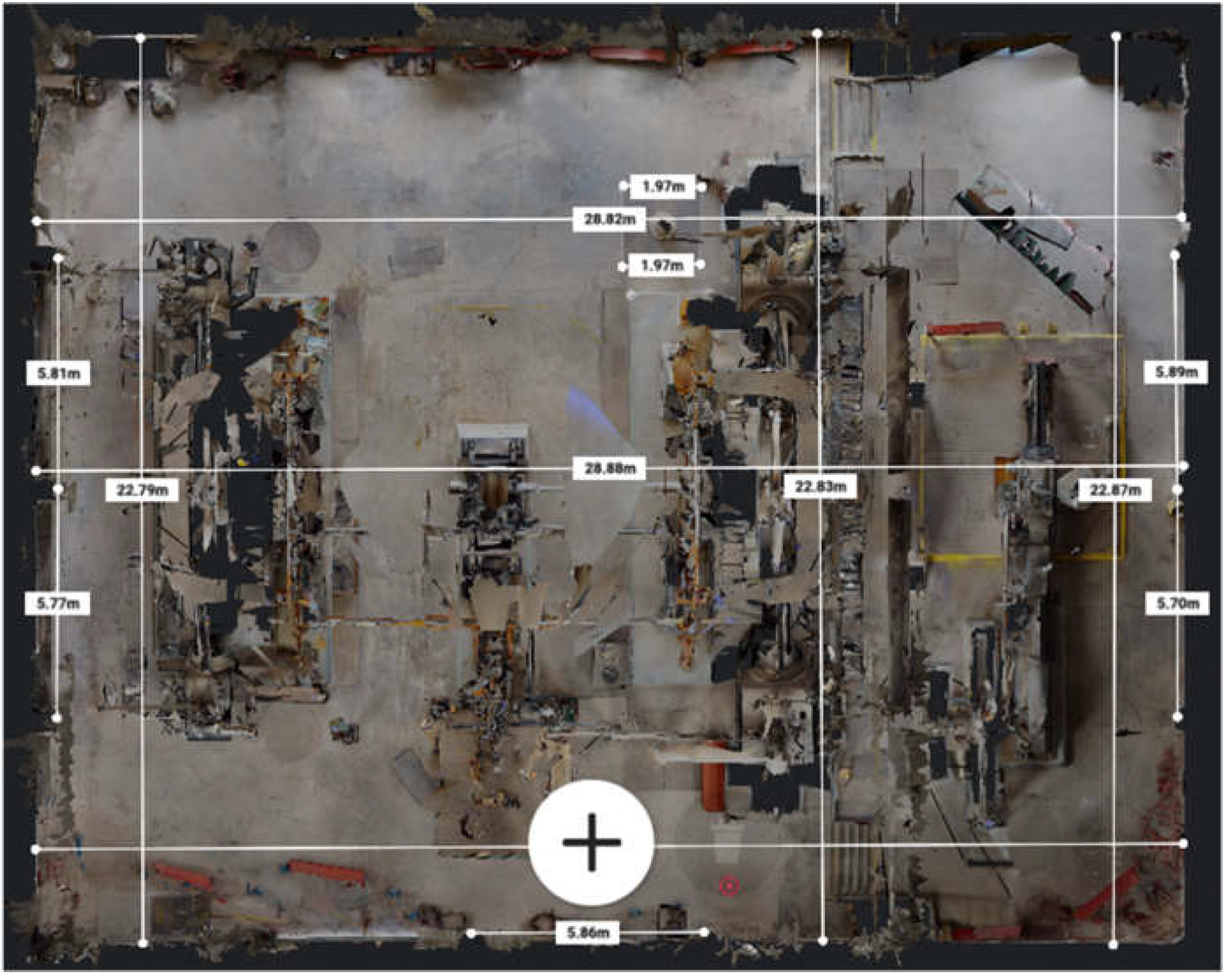
The paper’s primary goal was the geometrical quality check of the 3D cameras for industrial archaeology applications. This step allows us to finally prove or disprove our inferences regarding achievable accuracy and the calibration effect for the Matterport Pro camera. Furthermore, the field experiment results will help us interpret the outputs of distance comparison in Section 3.1 and Section 3.2. We have performed the test measurements using the obtained model to reach our aim. The test is based on the distance comparison between the map and on-site distances. In this way, we may check out the Matterport Pro accuracy in real field works and apply our scale coefficients from calibration. The historical map of the Quincy Mine Hoist Engine house was used to check the calibration quality (Figure 37). The control dimensions listed in Table 5 were taken from the map. The Matterport Pro distances were taken directly from the 3D model (Figure 38). After the calibration, the control dimensions were measured a second time, and the appropriately corrected differences were calculated.
The model was oriented so that the main house axes were parallel to the coordinate axes. Therefore, we can use different scales for perpendicular distances.
From Table 5, we may infer that after deploying the calibration coefficients, the distance accuracy has improved by up to 21%. The total accuracy constitutes 0.64% of the measured distance, which is much better than the 1% declared by the manufacturer. Despite the general enhancement, a systematic trend was not entirely eliminated throughout the calibration procedure. This means that 3D camera calibration is not a straightforward process. On the other hand, the probable reason for these results is the object’s size. Considering that the largest size of the test field was 12 m, which is almost three times less than a surveyed object, one may infer that the calibration has to account for the presumable size of the surveying object.
Now, let us get back to discussing the accuracy obtained from various comparison approaches. The RMS error for the measured distances in the test field is 1:880 or 0.11%. This result is six times better than the outcome of the actual field experiment. How can this be? To figure it out, we need to analyze the measurement scheme. The test field was surveyed from eight Matterport stations. In this case, the surveying distance varies from 4 m to 8 m; in other words, this range is believed to be optimal for Matterport surveying. Almost 95% of points were captured from each station. This means we have a high measurement redundancy, n = 8. Even if we suppose that the accuracy for a distance m d f = 0.64% is valid, then we will have the integrated distance accuracy for the test m D f .
m D t = m d f n = 0.23 % .
But this value includes the errors of non-marked point measurements. In the test field, we had the printed targets with reliably identifiable centers. In the actual object, we faced the need to measure the distances to vague faces or edges, which are damaged or poorly manufactured. In reality, the vague faces or edges could add the error m d e of up to ±0.02 m to the measured distances, which is equivalent to a relative error of 0.20%. If we rule out this error from the results of our field measurements, we obtain m D f = 0.18 % . That is pretty much the exact figure obtained in Section 3.1. As we are convinced that the overly optimistic results obtained are ensured by ideal measurement conditions. Therefore, despite the significant difference, both accuracies are compatible since they present different measurement conditions. Based on the presented results, the following recommendations should be accounted for to achieve the best geometrical data quality using the 3D indoor camera:
(1)
Try to ensure high data redundancy, increase the number of surveying stations, and use the camera field of view to be sure that each part of the object was captured six to eight times.
(2)
Place and capture the artificial targets with known coordinates. After the cloud generation, these targets will serve as an additional source of control and correction.
(3)
Perform camera calibration. It is preferable to calibrate the camera in the field conditions using targets with known coordinates.
(4)
Mark the points of interest.
A few recommendations can be derived for surveying and simulating industrial archaeology objects using Matterport Pro 3D or similar cameras. These recommendations improve the data reliability and make the processing procedure smooth. Among those are the following.
(1)
Pre-surveying design should be performed based on a preliminary sketch of the surveying object. Industrial objects have a very complex geometry, and to grasp all the features of the object, the preliminary design of the scanning stations must be developed.
(2)
The study has shown the high reliability of the Matterport Pro 3D camera in adverse conditions, e.g., low temperature and high humidity. These conditions go hand in hand with industrial archaeology objects. Anyway, the control of the environmental parameters is highly recommended before and during surveying.
(3)
These cameras operate in visual bands, and good lighting conditions must be ensured. This recommendation is crucial for industrial archaeology that deals with objects and rooms full of industrial equipment and “dead zones”.
(4)
The Matterport Pro 3D data processing is only possible with Matterport software. The surveyor has to bear this fact in mind. The further processing and integration of the Matterport Pro 3D data is only possible after pre-processing in Matterport-based software and export of surveying data into the point cloud.
The suggestions that are listed above could improve data accuracy and reliability.

5. Conclusions

The presented study has been dedicated to the accuracy-check and calibration procedure of the 3D indoor camera for industrial archaeology applications. As a case study, the Matterport Pro camera has been investigated. The general picture emerging from the study is that the calibration procedure for the 3D camera is an inevitable stage. The accomplished geometrical quality check has shown significant systematic errors in the camera’s results. A positive correlation was obtained between distances and systematic deviations. Given the fact that systematic errors exist, the calibration procedure was suggested and accomplished. This step allowed us to obtain the scale coefficients that are considered as calibration parameters. These calibration parameters were applied for the actual surveying results of the Quincy Mine Hoist Engine. The results provide convincing evidence showing that for the 3D camera, improved accuracy is possible. An accuracy enhancement of up to 21% was achieved. However, our findings are only generalizable within the study sample since the size of the calibration test field was considerably smaller than the surveyed object. Unaccounted systematic errors distorted the data in a still significant manner. These findings are less surprising if we consider the larger test field and more sophisticated calibration model. Future studies will have to consider the design of the calibration test field and the development of the new calibration model.

Supplementary Materials

The following supporting information can be downloaded at https://www.zenodo.org/record/7596938: Video S1: 3D Tour of Test Field; Video S2: Short Introduction QM; Video S3: 3D Trip Around Hoist Engine; Video S4: QM VR Unity3D.

Author Contributions

Conceptualization, R.S. and E.L.; methodology, R.S. and E.L.; software, N.K. (Nataliia Kulichenko), N.A. and N.K. (Naiman Kalabaev); validation, Z.A., M.S., N.A., K.P., N.K. (Nataliia Kulichenko) and N.K. (Naiman Kalabaev); formal analysis, R.S., Z.A. and K.P.; investigation, R.S., Z.A., M.S., N.A., K.P. and N.K. (Nataliia Kulichenko); resources, E.L.; data curation, Z.A. and K.P.; writing—original draft preparation, Z.A., M.S., N.A., K.P., N.K. (Naiman Kalabaev) and N.K. (Nataliia Kulichenko); writing—review and editing, R.S. and E.L.; visualization, R.S.; supervision, R.S. and E.L.; project administration, E.L.; funding acquisition, E.L. All authors have read and agreed to the published version of the manuscript.

Funding

This research received no external funding.

Data Availability Statement

Not applicable.

Acknowledgments

The authors would like to thank the Quincy Mine Hoist Association and museum authority for the opportunity to conduct this research.

Conflicts of Interest

The authors declare no conflict of interest.

References

  1. Palmer, M.; Neaverson, P. Industrial Archaeology. Principles and Practice, 2nd ed.; Routledge: London, UK, 1998. [Google Scholar]
  2. Conlin Casella, E.; Symonds, J.I. Industrial Archaeology. Future Directions; Springer: New York, NY, USA, 2005. [Google Scholar]
  3. Leon, I.; Pérez, J.J.; Senderos, M. Advanced Techniques for Fast and Accurate Heritage Digitisation in Multiple Case Studies. Sustainability 2020, 12, 6068. [Google Scholar] [CrossRef]
  4. Marín-Buzón, C.; Pérez-Romero, A.; López-Castro, J.L.; Ben Jerbania, I.; Manzano-Agugliaro, F. Photogrammetry as a New Scientific Tool in Archaeology: Worldwide Research Trends. Sustainability 2021, 13, 5319. [Google Scholar] [CrossRef]
  5. Huggett, J. Challenging Digital Archaeology. Open Archaeol. 2015, 1, 79–85. [Google Scholar] [CrossRef]
  6. Opitz, R.; Limp, F.W. Recent developments in high-density survey and measurement (HDSM) for archaeology: Implications for practice and theory. Annu. Rev. Anthropol. 2015, 44, 347–376. [Google Scholar] [CrossRef]
  7. Photogrammetry is the New Archaeological Photography: 3D Modeling at Abydos. Available online: https://abydos.org/blog/2019/3/13/photogrammetry-is-the-new-archaeological-photography-3d-modeling-at-abydos (accessed on 28 July 2023).
  8. Trepal, D.; Lafreniere, D.; Stone, T. Mapping Historical Archaeology and Industrial Heritage: The Historical Spatial Data Infrastructure. J. Comput. Appl. Archaeol. 2021, 4, 202–213. [Google Scholar] [CrossRef]
  9. Trepal, D.; Lafreniere, D.; Gilliland, J. Historical Spatial Data Infrastructures for Archaeology: Towards a Spatio-Temporal Big data Approach to Studying the Post-Industrial City. Hist. Archaeol. 2020, 54, 424–452. [Google Scholar] [CrossRef]
  10. Barazzetti, L.; Previtali, M.; Roncoroni, F. Can we use Low-Cost 360 Degree Cameras to create accurate 3D models? Int. Arch. Photogramm. Remote Sens. Spat. Inf. Sci. 2018, 42, 69–75. [Google Scholar] [CrossRef]
  11. Soria, G.; Ortega, L.; Feito, F.R.; Barroso, I. Procesamiento de imágenes panorámicas en patrimonio. Catedral de Jaén (Processing panoramic images in heritage. Jaen Cathedral). Virtual Archaeol. Rev. 2015, 6, 28–34. [Google Scholar] [CrossRef]
  12. Galizia, M.; Santagati, C. Low cost image-based modeling techniques for archaeological heritage digitalization: More than just a good tool for 3d visualization? Virtual Archaeol. Rev. 2013, 4, 123–129. [Google Scholar] [CrossRef]
  13. Chodoronek, M. The Use and Application of Photogrammetry for the In-Field Documentation of Archaeological Features: Three Case Studies from the Great Plains and Southeastern Alaska. Master Thesis, University of Nebraska, Lincoln, NE, USA, 2015. Available online: http://digitalcommons.unl.edu/anthrotheses (accessed on 20 July 2023).
  14. Shults, R. New Opportunities of Low-Cost Photogrammetry for Culture Heritage Preservation. Int. Arch. Photogramm. Remote Sens. Spat. Inf. Sci. 2017, 42, 481–486. [Google Scholar] [CrossRef]
  15. Pulcrano, M.; Scandurra, S.; Minin, G.; di Luggo, A. 3D cameras acquisitions for the documentation of cultural heritage. Int. Arch. Photogramm. Remote Sens. Spat. Inf. Sci. 2019, 42, 639–646. [Google Scholar] [CrossRef]
  16. Khoshelham, K.; Elberink, S.O. Accuracy and resolution of Kinect depth data for indoor mapping applications. Sensors 2012, 12, 1437–1454. [Google Scholar] [CrossRef] [PubMed]
  17. Costantino, D.; Angelini, M.G.; Caprino, G. Laser scanner survey of an archaeological site—Scala Di Furno (Lecce, Italy). Int. Arch. Photogramm. Remote Sens. Spat. Inf. Sci. 2010, 38, 178–183. [Google Scholar]
  18. Muhammed, Q.Q.; Saluh, M.M.; Al-Azawi, R.J.; Kadhim, A.C.; Shaker, R.M. Remote Sensing and Terrestrial Laser Scanning Techniques for Archaeological Site Analysis. In Proceedings Frontiers in Optics + Laser Science 2022 (FIO, LS), Technical Digest Series, Paper JW5A.92, Rochester, NY, USA, 17–20 October 2022; Available online: https://opg.optica.org/abstract.cfm?URI=FiO-2022-JW5A.92 (accessed on 20 July 2023).
  19. Marín-Buzón, C.; Pérez-Romero, A.M.; León-Bonillo, M.J.; Martínez-Álvarez, R.; Mejías-García, J.C.; Manzano-Agugliaro, F. Photogrammetry (SfM) vs. Terrestrial Laser Scanning (TLS) for Archaeological Excavations: Mosaic of Cantillana (Spain) as a Case Study. Appl. Sci. 2021, 11, 11994. [Google Scholar] [CrossRef]
  20. Chiabrando, C.; Spanò, A.; Sammartano, G.; Losè, L.T. UAV oblique photogrammetry and LiDAR data acquisition for 3D documentation of the Hercules fountain. Virtual Archaeol. Rev. 2017, 8, 83–96. [Google Scholar] [CrossRef]
  21. Fiz, J.I.; Martín, P.M.; Cuesta, R.; Subías, E.; Codina, D.; Cartes, A. Examples and Results of Aerial Photogrammetry in Archeology with UAV: Geometric Documentation, High Resolution Multispectral Analysis, Models and 3D Printing. Drones 2022, 6, 59. [Google Scholar] [CrossRef]
  22. Gärdin, D.; Jimenez, A. Optical Methods for 3D-Reconstruction of Railway Bridges Infrared Scanning, Close Range Photogrammetry and Terrestrial Laser Scanning. Master’s Thesis, Luleå University of Technology, Luleå, Sweeden, 2018. Available online: http://ltu.diva-portal.org/smash/get/diva2:1184613/FULLTEXT01.pdf (accessed on 20 July 2023).
  23. Thermal Imaging and “Seeing the Unseen” at Industrial Heritage Sites. Available online: https://www.linkedin.com/pulse/thermal-imaging-seeing-unseen-industrial-heritage-sites-scarlett (accessed on 28 July 2023).
  24. Gruenkemeier, A. 3D-documentation technologies for use in industrial archaeology applications. Int. Arch. Photogramm. Remote Sens. Spat. Inf. Sci. 2008, 37, 291–296. [Google Scholar]
  25. Monego, M.; Fabris, M.; Menin, A.; Achilli, V. 3-D survey applied to industrial archaeology by TLS methodology. Int. Arch. Photogramm. Remote Sens. Spat. Inf. Sci. 2017, 42, 449–455. [Google Scholar] [CrossRef]
  26. Agostinelli, M.; Clini, P.; Lancioni, N.; Quattrini, R.; Sabbatini, G. The Volponi’s Kiln in Urbino. Industrial archaeology and historic landscape in the cradle of the Renaissance. Documentation, survey and drawing. In Proceedings of the XXI International CIPA Symposium, Athens, Greece, 1–6 October 2007. [Google Scholar]
  27. Lobb, M.; Brown, T.; Leyland, J.; Bernard, V.; Daire, M.-Y.; Langouët, L. An estuarine tidescape of production: Terrestrial laser scanning of fixed fishing structures and a tide mill in the Léguer Estuary, Brittany. Antiquity 2020, 94, 1296–1313. [Google Scholar] [CrossRef]
  28. Pérez-Martín, E.; Herrero-Tejedor, T.R.; Gómez-Elvira, M.Á.; Rojas-Sola, J.I.; Conejo-Martin, M.Á. Graphic study and geovisualization of the old windmills of La Mancha (Spain). Appl. Geogr. 2011, 31, 941–949. [Google Scholar] [CrossRef]
  29. Rojas-Sola, J.I.; Galán-Moral, B.; la Morena-De la Fuente, D. Agustín de Betancourt’s Double-Acting Steam Engine: Geometric Modeling and Virtual Reconstruction. Symmetry 2018, 10, 351. [Google Scholar] [CrossRef]
  30. Bitelli, G.; Gatta, G.; Girelli, A.V.; Vittuari, L.; Zanutta, A. Integrated methodologies for the 3D survey and the structural monitoring of industrial archaeology: The case of the Casalecchio di Reno Sluice, Italy. Int. J. Geophys. 2011, 2011, 874347. [Google Scholar] [CrossRef]
  31. Rojas-Sola, J.I.; Porras-Galán, J.; García-Ruesgas, L. Reconstrucción digital 3D del patrimonio histórico de agustín de betancourt: La máquina para cortar hierba en canales navegables (Digital 3D reconstruction of agustin de betancourt’s historical heritage: The machine for cutting grass in waterways). Virtual Archaeol. Rev. 2016, 7, 20–30. [Google Scholar] [CrossRef]
  32. Sproat, D.; Toolis, R.; Hepher, J.; Rankin, D. Town and factory: An historic building survey of 200 years of Jhon Paton’s Kilncraigs woollen mill in Alloa, Clackmannanshire. Ind. Archaeol. Rev. 2004, 26, 21–36. [Google Scholar] [CrossRef]
  33. Pietroni, E.; Pescarin, S. VR cooperative environments for the interpretation and reconstruction of the archaeological landscape. Virtual Archaeol. Rev. 2010, 1, 25–29. [Google Scholar] [CrossRef]
  34. Barrilea, V.; Fotiaa, A.; Bilottaa, G.; De Carlo, D. Integration of geomatics methodologies and creation of a cultural heritage App using augmented reality. Virtual Archaeol. Rev. 2019, 10, 40–51. [Google Scholar] [CrossRef]
  35. Matterport. Matterport Pro2 3D Camera Specifications. Available online: https://support.matterport.com/s/article/Matterport-Pro2-3D-Camera-Specifications?language=en_US (accessed on 28 July 2023).
  36. Matterport. Scanning a Job Site for Construction Documentation. Available online: https://support.matterport.com/s/article/Scanning-a-Job-Site-for-Construction-Documentation?language=en_US&ardId=kA05d000001DWyYCAW (accessed on 28 July 2023).
  37. Society for Industrial Archeology (SIA). Available online: https://www.sia-web.org (accessed on 26 January 2023).
  38. Lehtola, V.V.; Kaartinen, H.; Nuchter, A.; Kaijaluoto, R.; Kukko, A.; Litkey, P.; Honkavaara, E.; Rosnell, T.; Vaaja, M.T.; Virtanen, J.P.; et al. Comparison of the selected state-of-the-art 3D indoor scanning and point cloud generation methods. Remote Sens. 2017, 9, 796. [Google Scholar] [CrossRef]
  39. Virtanen, J.-P.; Kurkela, M.; Turppa, T.; Vaaja, M.T.; Julin, A.; Kukko, A.; Hyyppa, J.; Ahlavuo, M.; von Numers, J.E.; Haggren, H.; et al. Depth camera indoor mapping for 3D virtual radio play. Photogramm. Rec. 2018, 33, 171–195. [Google Scholar] [CrossRef]
  40. Shults, R.; Levin, E.; Habibi, R.; Shenoy, S.; Honcheruk, O.; Hart, T.; An, Z. Capability of Matterport 3d Camera for Industrial Archaeology Sites Inventory. Int. Arch. Photogramm. Remote Sens. Spat. Inf. Sci. 2019, 42, 1059–1064. [Google Scholar] [CrossRef]
  41. Chen, Y.; Tang, J.; Jiang, C.; Zhu, L.; Lehtomäki, M.; Kaartinen, H.; Kaijaluoto, R.; Wang, Y.; Hyyppä, J.; Hyyppä, H.; et al. The Accuracy Comparison of Three Simultaneous Localization and Mapping (SLAM)-Based Indoor Mapping Technologies. Sensors 2018, 18, 3228. [Google Scholar] [CrossRef]
  42. Roe, M. Recording mining landscapes in the Yorkshire Dales: The Contribution of the Northern Mine Research Society. Ind. Archaeol. Rev. 2006, 28, 117–122. [Google Scholar] [CrossRef]
  43. Photogrammetry in Industrial Heritage: Remote Sensing at the Quincy Smelter, Part 2. Available online: https://www.linkedin.com/pulse/photogrammetry-industrial-heritage-remote-sensing-quincy-scarlett (accessed on 28 July 2023).
  44. He, Y.; Liang, B.; Yang, J.; Li, S.; He, J. An Iterative Closest Points Algorithm for Registration of 3D Laser Scanner Point Clouds with Geometric Features. Sensors 2017, 17, 1862. [Google Scholar] [CrossRef] [PubMed]
  45. Estépar, R.S.J.; Brun, A.; Westin, C.F. Robust Generalized Total Least Squares Iterative Closest Point Registration. In Medical Image Computing and Computer-Assisted Intervention—MICCAI 2004; MICCAI 2004. Lecture Notes in Computer Science; Barillot, C., Haynor, D.R., Hellier, P., Eds.; Springer: Berlin/Heidelberg, Germany, 2004; Volume 3216. [Google Scholar] [CrossRef]
  46. Besl, P.J.; McKay, N.D. A Method for Registration of 3D Shapes. IEEE Trans. Pattern Anal. Mach. Intell. TPAMI 1992, 14, 239–255. [Google Scholar] [CrossRef]
  47. Quincy Mining Company HAER. A Look at the Architecture and Communities of the Quincy Mining Company; Quincy Mine Hoist Association (QMHA): Houghton, MI, USA, 2019. [Google Scholar]
  48. Quincy Mine Hoist Association (QMHA). Available online: https://quincymine.com (accessed on 26 January 2023).
  49. JAG3D. Java·Applied·Geodesy·3D. Available online: https://software.applied-geodesy.org (accessed on 26 January 2023).
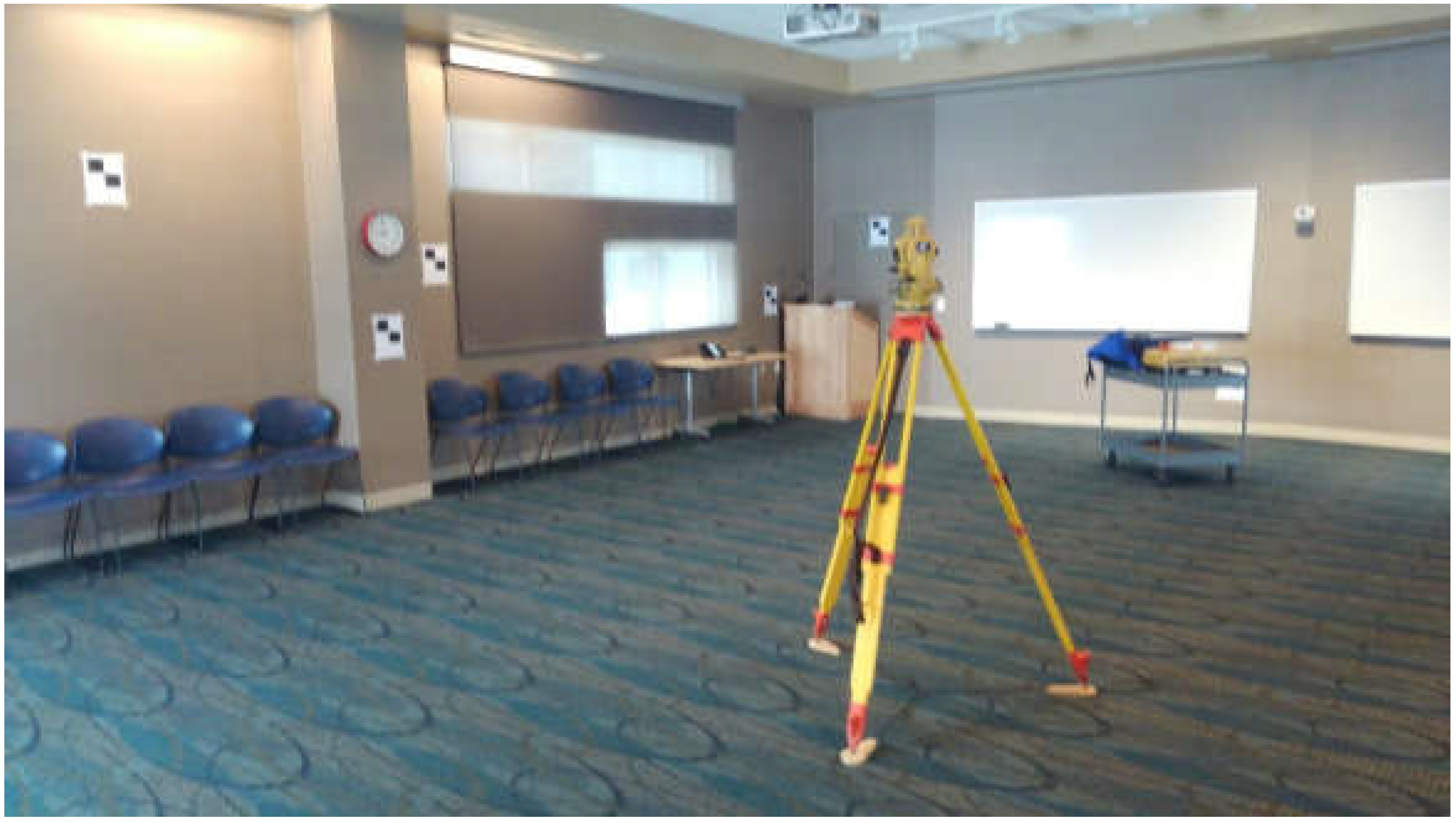
Figure 1. Coordinating reference targets using the total station.
Heritage 06 00327 g001
Figure 2. Test field scanning by FARO Scanner.
Heritage 06 00327 g002
Figure 3. Point cloud of the test field with control targets retrieved from FARO Scanner data.
Heritage 06 00327 g003
Figure 4. Test field surveying by the Matterport Pro camera.
Heritage 06 00327 g004
Figure 5. Three-dimensional model of the test field after processing by the Matterport server.
Heritage 06 00327 g005
Figure 6. Horizontal plan of the test field after processing by the Matterport server.
Heritage 06 00327 g006
Figure 7. ICP orientation workflow: (a) two point clouds; (b) discrepancies determination; (c) first transformation; (d) nth transformation iteration.
Heritage 06 00327 g007
Figure 8. The location of the Quincy Mine at the Upper Peninsula Michigan.
Heritage 06 00327 g008
Figure 9. Archive map of the Quincy Mine, 1906; the scope of the study is in a boxed area (the image courtesy Michigan Technological University J. Robert Van Pelt and John and Ruanne Opie Library Archive).
Heritage 06 00327 g009
Figure 10. General view of the Quincy Mine, 1882–1920, with the Hoist Engine house leftward (archive image) [47].
Heritage 06 00327 g010
Figure 11. Cross-section of the Quincy Mine Hoist Engine house, 1921 (archive image) [47].
Heritage 06 00327 g011
Figure 12. Current view of the Quincy Mine Hoist Engine house.
Heritage 06 00327 g012
Figure 13. The model of the shaft inside the Quincy Mine Hoist Engine house.
Heritage 06 00327 g013
Figure 14. The Quincy Mine Hoist Engine view.
Heritage 06 00327 g014
Figure 15. Distances deviations: Total station vs. Matterport.
Heritage 06 00327 g015
Figure 16. Distances deviations: Total station vs. FARO Scanner.
Heritage 06 00327 g016
Figure 17. Distances deviations: FARO Scanner vs. Matterport.
Heritage 06 00327 g017
Figure 18. Histogram of deviations: Total station vs. Matterport.
Heritage 06 00327 g018
Figure 19. Histogram of deviations: Total station vs. FARO scanner.
Heritage 06 00327 g019
Figure 20. Histogram of deviations: FARO scanner vs. Matterport.
Heritage 06 00327 g020
Figure 21. Results of the linear approximation.
Heritage 06 00327 g021
Figure 22. Distance deviations after linear trend correction.
Heritage 06 00327 g022
Figure 23. Colored 3D point cloud after C2C comparison; distance units are meters. Color-scale units are meters.
Heritage 06 00327 g023
Figure 24. Colored 3D point cloud after blunder exclusion; distance units are meters. Color-scale units are meters.
Heritage 06 00327 g024
Figure 25. C2C distance deviations after the systematic error correction; distance units are meters. Color-scale units are meters.
Heritage 06 00327 g025
Figure 26. Vector plot of transformation errors in the horizontal plane.
Heritage 06 00327 g026
Figure 27. Vector plot of transformation errors in 3D space.
Heritage 06 00327 g027
Figure 28. Flowchart of outdoor and indoor surveying of the Hoist Engine house.
Heritage 06 00327 g028
Figure 29. Flowchart of outdoor and indoor surveying of the Hoist Engine house.
Heritage 06 00327 g029
Figure 30. Three-dimensional model of the Hoist Engine house.
Heritage 06 00327 g030
Figure 31. One of the Matterport Pro surveying stations inside the Hoist Engine house.
Heritage 06 00327 g031
Figure 32. Panoramic images of the Hoist Engine: (a) from the ground; (b) from the platform.
Heritage 06 00327 g032
Figure 33. The whole data set obtained by Matterport Pro with places of the camera set up.
Heritage 06 00327 g033
Figure 34. The view screenshot from the platform surrounding the hoist engine.
Heritage 06 00327 g034
Figure 35. The ladder height measurement option in the Matterport software menu.
Heritage 06 00327 g035
Figure 36. The measurements of the Hoist Engine concrete foundations in the Matterport software menu.
Heritage 06 00327 g036
Figure 37. The map of the Quincy Mine Hoist Engine house (dimensions are in feet) [47].
Heritage 06 00327 g037
Figure 38. Distance measurements according to the map of the Quincy Mine Hoist Engine house.
Heritage 06 00327 g038
Table 1. Descriptive statistics of the distance deviations.
Parameters, mFARO Scanner vs. Matterport, mTotal Station vs. Matterport, mTotal Station vs. FARO Scanner, m
Mean0.02160.03050.0088
Median0.02240.03060.0093
Standard Deviation0.01410.01660.0044
Range0.07820.09030.0224
Minimum−0.0077−0.0086−0.0025
Maximum0.07050.08160.0199
Count210210210
Table 2. ICP transformation accuracy and C2C comparison.
PointsOrientation RMSE, mNo Scale Adjust, mOrientation RMSE, mScale Adjust, m
C2C MeanC2C RMSC2C MeanC2C RMSEScale
Original clouds0.01040.01290.00930.00720.00620.00411.003381
2M0.00920.01340.01420.00870.00840.00791.000630
1M0.01190.00640.00550.01210.00630.00460.999946
500K0.01570.00640.00550.01610.00630.00460.999891
200K0.02360.00710.00640.02400.00640.00460.999767
Table 3. List of transformation parameters.
ParameterValueσParT ≤ Φ − 1|H0
Tx1527.4054 m1.7 mm
Ty1521.7045 m1.8 mm
Tz28.8318 m3.9 mm
q0−0.999917640.00000139
q10.001396300.00017123
q20.000169000.00013625
q3−0.012757060.00010727
dsx3268.3 mm/km273.0 mm/km
dsy3898.6 mm/km346.4 mm/km
dsz5574.1 mm/km2376.8 mm/km
Rx0.17749 gon21.77 mgon
Ry0.02378 gon17.38 mgon
Rz398.37571 gon13.66 mgon
Table 4. Results of 3D Helmert transformation.
PointX, mY, mZ, mσX mmσY mmσZ mmεX mmεY mmεZ mm
A011518.44871521.755629.12973.13.13.4−7.5−2.3−2.6
A021518.39321524.000030.82593.13.13.21.92.73.4
A031518.36981524.897630.48003.13.13.10.14.4−1.9
A041518.33881526.244629.86433.13.13.2−0.72.31.9
A051518.30441527.675831.17953.13.23.44.50.1−2.2
A061522.24791528.298829.78963.13.13.2−0.62.50.9
A071523.42661528.330031.05453.03.13.2−0.7−1.72.7
A081525.15671528.372829.29593.03.13.30.52.60.9
A091526.77901528.416630.42973.13.13.12.0−1.80.5
A101529.56831528.491030.10513.13.13.2−0.4−2.3−1.4
A111530.40931527.920629.75003.23.13.2−1.2−3.0−0.9
A121530.46401526.996230.24383.13.13.2−4.7−0.7−1.6
A131530.71691525.614730.78943.13.13.2−0.6−2.0−0.8
A151530.58361520.169330.76963.23.23.34.61.72.3
A161529.80391519.330230.07773.23.23.35.34.35.2
A171525.66511519.230230.49833.13.13.1−5.81.7−3.5
A181524.95421519.614430.02433.13.13.1−0.6−1.1−1.5
A191523.46131519.168431.00583.13.13.2−0.40.9−2.3
A201518.92531519.044829.80033.13.23.22.1−4.31.5
A211518.46641519.285730.42973.13.23.22.1−3.9−0.6
Table 5. Results of distance comparison in the Quincy Mine Hoist Engine house.
DistancesControl Distances from Map, mMatterport Distances, mDifferences, mCorrected Matterport Distances, mCorrected Differences, m
15.815.79−0.025.810.003
25.815.77−0.045.79−0.018
35.815.7−0.115.72−0.088
45.815.830.025.850.043
55.735.66−0.075.68−0.048
621.97−0.031.98−0.024
721.97−0.031.98−0.024
821.97−0.031.98−0.024
923.1622.87−0.2922.96−0.201
1023.1622.83−0.3322.92−0.241
1123.1622.79−0.3722.88−0.281
122928.82−0.1828.91−0.086
132928.88−0.1228.97−0.026
142928.89−0.1128.98−0.016
1528.428.24−0.1628.33−0.068
Mean14.66 −0.12514.58−0.073
RMS m d f 0.120 0.094
Relative 1:122 (0.82%) 1:155 (0.64%)
Disclaimer/Publisher’s Note: The statements, opinions and data contained in all publications are solely those of the individual author(s) and contributor(s) and not of MDPI and/or the editor(s). MDPI and/or the editor(s) disclaim responsibility for any injury to people or property resulting from any ideas, methods, instructions or products referred to in the content.