Article

Ballasting a Mid-19th Century Chilean Navy Armed Transport: Archaeometallurgical Insights into Cast Iron Ingots Recovered from the Barque Infatigable (1855)

1
Millennium Nucleus Ocean, Heritage & Culture, Valparaiso 2340000, Chile
2
ARQMAR, Centre for Maritime Archaeology Research of the Southeastern Pacific, Valparaiso 2340000, Chile
3
ÀRKA—Maritime Archaeology, Valparaiso 2340000, Chile
4
National Scientific and Technical Research Council (CONICET), Autonomous City of Buenos Aires C1425FQB, Argentina
5
Institute of Archaeology, Faculty of Philosophy & Letters, University of Buenos Aires, Autonomous City of Buenos Aires C1002ABE, Argentina
6
Independent Researcher, Santiago 7510989, Chile
7
Department of Metallurgical Engineering, University of Santiago de Chile, Santiago 9170020, Chile
*
Author to whom correspondence should be addressed.
Heritage 2023, 6(2), 2126-2151; https://doi.org/10.3390/heritage6020114
Submission received: 21 December 2022 / Revised: 13 February 2023 / Accepted: 13 February 2023 / Published: 19 February 2023

Abstract

:
Ballast is essential for vessels to lower their centre of gravity, improve stability, and ease their motion during sailing. During the modern period, heavy materials used for ballasting ships were an issue of particular concern for both authorities and ship owners, subjected to increasing control, regulation, and standardisation. These items represent a very common find in wreck sites and deserve special attention, as their characteristics, distribution, and provenance can deliver critical information for assessing where the vessel was ballasted, sailing routes, ship tonnage, and site formation processes. This article is centred on pig iron ingots, introduced in the early 18th century in sailing warships and shortly thereafter in sizeable merchant vessels, a type of ballast which is frequently overlooked in archaeological research. In particular, specimens retrieved from the Chilean Navy armed transport Infatigable (1855) were analysed through macroscopic and physicochemical characterisation using LM, SEM-EDS, WD-XRF, and IGF. The results obtained indicate the ingots were manufactured with cast iron of different quality, suggesting they may have come from different production centres. The investigation resulted in a better understanding of ballasting practices on a South American navy ship in the early post-independence period and provided new data for discussions of off-site and non-nautical technological issues, such as the materials, knowledge, and techniques associated with the production of pig iron in the mid-19th century.

Graphical Abstract

1. Introduction

The stability of sailing vessels depends on a precise balance between hull shape and ballast—in addition to other weighted objects carried on board as cargo, supplies, or ordnance—and the dynamic action of sea and wind. Thus, in general, ballast can be broadly defined as an extra heavy weight introduced into the vessel to lower its centre of gravity and therefore improve its stability and ease of motion during sailing [1] (see pp. 2−3, on how ballast influences ship stability, freeboard, draft, and trim). For that reason, during the modern period the weight used as ballast in the holds of ships, namely wooden-hulled sailing vessels, was an issue of particular concern for both authorities and ship owners and, as such, was subjected to increasing control and regulation. This was largely the situation with warships and sizeable merchant vessels sailing to overseas territories, which used different types of solid heavy materials as ballast, depending on their availability, requirements, and costs. However, a tendency toward a standardised practice can be observed beginning in the latter half of the 18th century, in particular, associated with the adoption of iron ballast (see below).
Ballast is a very common find in shipwreck sites. In maritime and nautical archaeology, it has been widely acknowledged that the study of ballast deserves special attention, as its characteristics, distribution, and provenance can yield valuable information for assessing where the vessel was ballasted, sailing routes, ship tonnage, and site formation processes [2] (pp. 413–418); [3] (p. 22); [4] (pp. 131–132). A cluster of stones used as ballast can be one of the few types of evidence remaining from a shipwreck in situ and, thus, can help delimit the place where the ship was lost [5]; also, ballast mounds can help preserve structural remains and other artefacts deposited below them [6,7]. Morphometric and distributional studies of ballast have shed light upon decisions related to the ship stowage and shipping mishaps, among other aspects [8]. Surface marks on ingots, such as the date of manufacture or the foundry’s name, can also prove highly diagnostic for dating and provenance studies [9] (pp. 27–32). Previous studies that combined archaeometric characterisation of stones, coral, and metal ballast remains with documentary evidence have provided new information about the characteristics and service life of several modern European- and American-built vessels [10,11,12,13,14]; [11] (annexe 2, pp. 153–154); see also [1] and references therein.
This article focuses on pig iron ingots (kentledge), a special kind of ballast introduced in the early 18th century for use in sailing warships and shortly thereafter in large merchant vessels, both in Europe and overseas. A comprehensive examination of the ballast remains from Infatigable (1855), a three-masted sailing vessel adapted by the Chilean Navy as an armed transport, which exploded and sank in Valparaiso harbour, was conducted. This study aimed to gather new data about the ballasting practices of a South American navy in the early post-independence Republican period, considering possible foreign influences (e.g., Anglo-American and Spanish practices) and local preferences. The value of an archaeometric approach should be highlighted here; in particular, the physicochemical characterisation of specimens using LM, SEM-EDS, XRF, and IGF provided new data for discussing off-site and non-nautical technological issues, such as the materials, knowledge, and techniques associated with mid-19th century pig iron production. Finally, considering technological data, and by comparison with other contemporaneous pig iron specimens, the quality of the materials was examined as a proxy for relative dating and provenance assessment of the ingots.

1.1. Infatigable: A Chilean Navy Armed Sailing Transport

Infatigable (meaning indefatigable in English) was a ~200-ton three-masted sailing barque adapted as an armed transport by the Chilean Navy and destined primarily to supply the colony of Punta Arenas on the Magellan Strait. The vessel was lost at anchor on August 3, 1855, after a massive explosion in the powder magazine and subsequent fire destroyed and rapidly sank the vessel. The Infatigable wreck site was discovered in 2005 during the archaeological assessment for a dredging project at Terminal No. 1 of the Port of Valparaiso (33° S), on Chile’s central coast (Figure 1).
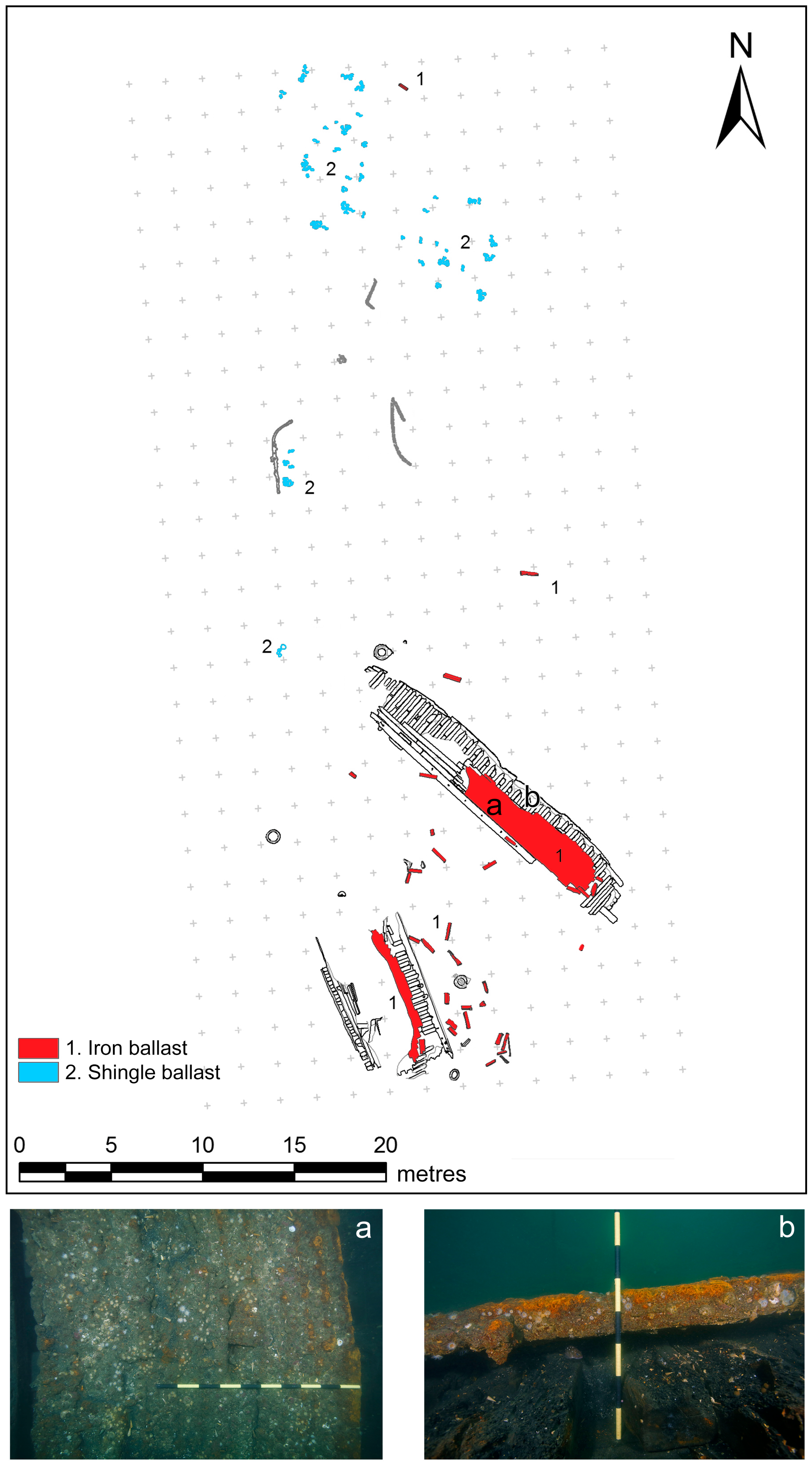
The main visible features at the site are two wooden structures 20 m long, corresponding to the port and starboard sides of the ship, projecting approximately 30 cm above the seabed. A concreted layer of pig iron ballast remains in situ, while several individual pigs (ingots) lay dispersed. The archaeological signature of the artefact finds exhibits an apparent north-south distribution, with materials projecting northward from the hull, including several clusters of stone shingle ballast in the form of gravel (cobbles) (Figure 2).
The wreck—designated site S3 PV—has been archaeologically investigated comprehensively for more than a decade [15,16]. The survey and excavations conducted recorded the structural remains of the hull and produced numerous varied artefact assemblages for analysis. The material culture of Infatigable reflects the complex cultural influence of several traditions coexisting onboard mid-19th century Chilean Navy vessels, thereby providing a hitherto untapped primary source of data about South American navies of the period.
Infatigable was a former American merchant vessel named Haydée, presumably built in Baltimore in 1847–1848. The vessel was purchased by Valparaiso shipowners in February 1850 in San Francisco, California, during the Gold Rush, renamed Honoria, and destined for the Chilean coastal trade. Acquired by the Chilean Navy in 1851, this armed transport supplied the colony of Punta Arenas on the Magellan Strait on twice-yearly voyages, transporting military regiments and their families, civil servants, and convicts, in addition to provisions and livestock [16].
Documentary research of Navy records of the period has provided scarcely any information on the ballasting practices on board Chilean naval vessels, so the subject has remained largely unexplored to date.

1.2. Historical Remarks on Ballast and Ballasting of Vessels in the Modern Period

Late 18th- and 19th-century marine dictionaries and manuals provide valuable source material on ballast and the procedures for ballasting sailing vessels. According to Falconer, ballast is “a certain portion of stone, iron, gravel, or such like materials, deposited in a ship’s hold, where she has either no cargo, or too little to bring her sufficiently low in the water. It is used to counter-balance the effort of the wind upon the masts, and give the ship a proper stability…”, concluding that “the whole art of ballasting, therefore, consists in placing the center of gravity to correspond to the trim and shape of the vessel, so as neither to be too high nor too low; neither too far forward, nor too far aft; and to lade the ship so deep, that the surface of the water may nearly rise to the extreme breadth amidships; and thus she will be enabled to carry a good sail, incline but little, and ply well to the windward” [17] (ballast).
Moore’s [18] and Steel’s [19] brief definitions, as well as the one offered by Meade [20] (p. 456), are summarized versions of the previous one. Spanish dictionaries of this period also offered a glimpse into the type of ballast usually used on ships. O’Scanlan defined lastre (or enjunque) as the “stone, iron, sand, shingle, or another heavy material which is placed and arranged in the hold of a ship, aiming to properly draught into the water, and acquire stability” [21] (p. 332, translation by the authors). De Lorenzo, De Murga, and Ferreiro referred to it in the same way [22] (p. 324). In the corrected and enlarged version of Falconer’s dictionary, Burney added a mention on how both iron and shingle ballast should be arranged in the hold of ships belonging to the Royal Navy and the merchant service, according to the vessel shape and interior features [23] (p. 30).
Broadly speaking, the stowage of the ballast and cargo of a ship was a very delicate procedure, given its implications for the vessel’s trim (forward and aft floating position), motion, and stability. Therefore, the quality, proportion, and distribution of weight in the ship’s hold, calculated according to the ship’s characteristics and the purpose of navigation, were subject to strict rules [23] (pp. 507, 581–582); [24] (pp. 63–64). Permanent ballast could be incorporated at the time a ship was built, as part of its design, to provide a minimum degree of stability, while mobile ballast was used according to sailing requirements [10] (pp. 5–6). For instance, 38 tons of iron ballast were added to the port side of HMS Victory to correct a list to starboard after her first floating in 1765 [25] (p. 260); [26] (p. 120). An incorrect calculation or inappropriate use of ballast and other weights on board have been identified as significant factors in the lack of stability and subsequent loss of ships under sail, such as HMS Sirius (1780–1790) [27] and USS Somers (1846) [28] (pp. 71–72), among others.
Ships voyaging ‘in ballast’ (en lastre, in Spanish) or loaded with cargo used different types of materials as ballast, such as stones of various sizes (e.g., cobbles, pebbles, and sand), earth (dirt), coral, cement, and metal bars and ingots [1] (pp. 16–21). Spanish ships travelling to and from Spain and its American colonies in the late 18th century were, by preference—and, for a while, by command—stone-ballasted because of that material’s advantages over sand, which tended to clog the ship’s pumps. This and other regulations related to the acquisition and management of ballast reflect an increasing interest in these matters on the part of the state and naval authorities [3] (p. 23 & 26); [4] (pp. 137–138).
For merchant ships, all or part of the cargo usually served as ballast, and the higher the load density, the less other ballast was needed. Semi-finished products such as iron bars and straps were a typical high-density cargo carried in modern-era wooden ships [29,30,31,32]. The high number of bricks found in the Dutch East Indiaman Vergulde Draeck (1656) were destined for Batavia (present-day Jakarta) as ballast [33] (p. 288 & Figure 19). The ballast of small and/or private vessels used for cabotage could be rather eclectic, and ships visiting multiple ports of call could also carry a diverse array of materials in their holds. Along with the aforementioned elements, other heavy pieces used as complementary ballast might include old iron guns, which were commonly placed in the mid-ship area of the ship’s hold.
On the other hand, regular metal ballast was comprised mainly of pig iron, lead ingots, and scrap metal. The introduction of these materials as primary ballast occurred during the 18th century, as will be further explained below. However, they also served this function earlier, when carried as supplies or cargo, a case in point being the part-cargo heavy metals (lead, iron, copper, tin) used as compensatory low stowage factor (i.e., high cargo density) materials on board vessels in antiquity [34] (p. 357). The following section provides a brief introduction to the use of iron ballast on board European (mostly British and Spanish) and Anglo-American warships and its expansion to other vessels.

2. Research Background

2.1. Kentledge or Pig Iron Ballast

The diversity of materials used as ballast on board wooden sailing ships is recorded in both documentary sources and shipwrecks around the world. Iron ballast in particular was introduced relatively late, at first in ships of war. Initial experiences in Britain dating to the early 18th century included the use of old iron guns and ammunition, as well as the lead cast into weights. The first serious attempt to introduce pig iron as ballast in warships is attested to in the Royal Navy’s contracts with private suppliers in the late 1720s [35]. According to Lavery, despite early trials, its use remained very limited until the following century. A significant change took place around the mid-18th century: a list of Royal Navy warships dated 1752 specifies that its vessels carried only one type of ballast, most likely shingle, while in 1756, another list including almost all these same vessels refers to the use of a combination of iron and shingle ballast. By the end of the century, Royal Navy vessels were usually ballasted with a combination of iron ingots and shingle (in a 1:4 ratio, on average, although this could vary significantly), with amounts being defined according to the number of guns [36] (p. 186).
Pig iron ingots were also known as ‘kentledge’ in Britain. This term is defined in early 19th-century dictionaries as “pigs of iron for ballast, laid upon the floor, near the keelson, fore and aft” [18] (kentledge); see also [23] (pp. 210, 343). Broadly speaking, iron ballast blocks were stowed in the lower part of the ship’s hold, i.e., close to the keelson at the midship section. Other ballast, such as shingle, was placed on top of the kentledge [36] (see pp. 186–187). If any cargo was loaded, it was placed above the latter. The shingle ballast also served to receive the first layer of large water casks carried on board, traditionally designated ’ground tier’. Figure 3 provides an example of how iron and shingle ballast and casks were typically stowed in the main hold of a sailing vessel of the period.
In Falconer’s new dictionary, the table titled “Ballast allowed to the following Ships”, provides a general idea of the quantity of iron and shingle ballast (in tons) required for ships of the line, frigates, and unrated British vessels [23] (p. 30). A similar panorama is reported in his English-Spanish dictionary by Martínez de Espinosa y Tacón [38] (p. 29), whose account is grounded in the information available (published) in the early 19th century. Other treatises of the period also report on the type and quantity of ballast carried on board according to the number of guns and tonnage of vessels.
From the 16th to the 18th century, the Spaniards relied largely upon large river cobbles for ballasting their ships, yet during the last third of the latter century, naval vessels also began to use pig iron ingots. The frigate Santa Maria Magdalena (1773–1810) was ballasted with this type of material to address the stability problems that previous vessels built under Francisco Gautier’s shipbuilding system had shown. A common practice among Spanish vessels was to use iron and shingle ballast, which might also be combined with discarded heavy iron objects such as cannons and ammunition [39] (pp. 352–355). For instance, an inspection of the frigate Nuestra Señora de las Mercedes (1804), anchored at the port of Montevideo on 5 June 1804, reported 549 quintales (i.e., hundredweights, cwt) of iron ballast and 150 cwt of zahorra (gravel) [40] (p. 334).
Ballasting ships with pig iron was a delicate and time-consuming task that required significant preparation. Brady, describing these procedures on board United States naval vessels, states that the hold had to be cleaned, swept, and whitewashed. Hoop poles were placed athwart ship, with each pig iron resting on at least two of them. Rust had to be removed from each pig, which in turn had to be whitewashed. Each pig had to be weighted and stowed following the mould of the vessel to achieve the best sailing trim and care was taken to distribute the same number of pigs on each side of the keelson. Finally, a draft of the ballast was produced, recording the exact number of pigs, the exact position they occupied, and their exact weight [41] (pp. 126–127).
A general description of the main features of ballast ingots is provided by O’Scanlan, De Lorenzo, and others: the lingotes (or galápagos, both Spanish terms for ingots) were generally made of cast iron, with a parallelepiped shape and in various sizes and weights; the ingots also had a hole in one head to allow their handling. A smaller type of iron block, known as lingotes de romaneo (shifting ballast), was also used on board to shift the position of ballast fore and aft, as required, to improve the ship’s behaviour [21] (p. 341); [22] (pp. 332–333). If this was the case for Spanish ingots by the first half of the 19th century, the basic morphology of these items seems to have been quite similar between the two nations. British ones also came in two main standardised dimensions, as both documentary sources and evidence from shipwrecks indicate (see below).
Iron ballast blocks are commonly found at wreck sites of sailing warships and other vessels of the period, thus providing useful archaeological data on their introduction, prevalence, and characteristics. As for the early use of kentledge as permanent ballast in British warships, evidence from the second quarter of the 18th century is still rare and includes HMS Looe (1741–1744) and HMS Fowey (1744–1748) [42] (p. 67); [43] (pp. 101–102); [44] (pp. 111–114). For subsequent periods, several wreck sites containing iron ballast corresponding primarily to British, but also to French, Spanish, and Anglo-American naval vessels from the second half of the 18th century [44] (p. 112); [45] (p. 37); [46,47] (pp. 74–75); [48,49] (p. 51); [50] (pp. 37–47) and into the 19th century [44] (p. 112); [51,52] (pp. 63 & 67–69); [53] (p. 66); [54] (pp. 217–223) have been investigated and reported.
The adoption of kentledge by cargo-carrying merchant sailing vessels is less well-documented. The drop in iron production costs during the late 18th century most likely favoured this process [44] (p. 112). Nonetheless, archaeological evidence suggests that this kind of ballast was in use earlier still in merchantmen, as the remains of the Sussex, an English East Indiaman lost in the Indian Ocean in 1738, demonstrate [55] (p. 83). Iron ballast was also employed by French trading ships as early as the 1740s, as attested to by the remains of the East Indiaman Prince de Conty (1746) [56] and the frigate L’Aimable Grenot (1749), a former privateer converted into a merchant vessel assigned to the Spanish trade route [9] (pp. 27–32); [57]. By the end of the century, ships engaged in the transatlantic slave trade between Mozambique and Brazil employed iron ballast also, as the discovery of the Portuguese slave ship São José Paquete de Africa (1794), and the subsequent recovery of an assemblage of cast iron blocks from the wreck site, reveal [58].
Along with their characteristic dimensions, pig iron ingots could also display diagnostic marks on their surface. Pieces used on board Royal Navy vessels were usually stamped with the broad arrow used to mark British Crown property, as the findings from HMS Fowey (1744–1748), HMS Sirius (1780–1790), and HMS Pomone (1805–1811) demonstrate [44] (pp. 112–113 & Figure 8.2); [45] (p. 37); [54] (pp. 217 & Figure 39). Other possible marks include the year of production and the manufacturer’s name. For instance, ingots found at the wreck site of L’Aimable Grenot (1749) were stamped with the years 1746 and 1747 and the names POTUXENT and Stepn Onion, respectively, which allowed archaeologists to trace their place of manufacture [9] (pp. 27–32); [57].
For the early 19th century, archaeological evidence related to merchant and fishing vessels suggests a more diverse scenario in the use of iron ballast in sailing vessels. The fact that American traders and British whalers operating in the Pacific were carrying iron ballast during the first decades [59] (pp. 22 & 39–40); [60] (pp. 95–98); [61] (p. 594) indicates that this type of ballast was more affordable and not reserved exclusively for high-performance naval vessels. However, stone continued to be employed as prime ballast throughout the century. This extended use is reflected in the wreck sites of several vessels, such as the American China trader Rapid (1811) [60] (pp. 149, 153–155), the Valparaiso-based Guatemalan ship Francisco Álvarez (1868) [62] (p. 53), and the Brazilian clipper Redemptora (1898) [63], among others.
The study of pig iron ingots can provide new and more detailed information about this type of ballast, yet this evidence has not been the subject of extensive research. Data retrieved thus far from iron ballast is focused on the main dimensions (form, size, and weight), surface marks, and distribution of ingots within the hold. With very few exceptions [64] (for a specific detailed study on the ballast recovered from H.L. Hunley, 1861), data collection and reporting standards on kentledge varies widely, and detailed artefact information is seldom provided. Moreover, an undetermined number of shipwreck case studies remain as difficult-to-access grey literature. The resulting lack of quality datasets hinders the development of a systematic approach to the subject, and this bias remains a serious problem for academic research.
Another relevant aspect is that scientific data on the material characteristics of ingots provide a valuable source of information for assessing cast iron production in general, the manufacturing of semi-finished products, and the quality of these specific ballast elements. Despite its potential, however, archaeological finds of this kind have seldom been characterised empirically and systematically [65,66]. In this context, archaeometric and comparative approaches must be highlighted for their potential for exploring materials knowledge and technological change in both naval and metallurgical industries of the modern period [67,68,69] (and references therein). This study of the cast iron pieces from Infatigable (1855) is framed within this scope of research.

2.2. A Brief Definition of Cast Iron

According to material scientists [70] (pp. 327–338); [71] (pp. 335–336, 416–422); [72] (pp. 37–38), cast iron is generally defined as a ternary iron-carbon-silicon alloy with a carbon content >2.11 wt%, which can often contain phosphorous, manganese, and/or sulphur as alloying additions or impurities, and other elements in low percentages. Normally, cast iron’s carbon content ranges from 2.11 to 4.5 wt% (and up to 6.7 wt%).
There are different types of cast irons, and their production, physical properties, and microstructure all depend upon both chemical composition (especially the content of carbon and silicon) and the manufacturing process, in particular the cooling velocity (see below). The melting point of cast iron with 3 to 4.5 wt% of carbon, for instance, is about 1150 to 1300 °C, significantly lower than wrought iron and steel. Therefore, this type of cast iron is easily melted and cast. Moreover, each type of cast iron exhibits distinctive mechanical properties.
The most common types of cast iron found as ancient or modern archaeological remains correspond to white, grey, and mottled cast iron. In white cast iron, most of the carbon appears as iron carbide or cementite, a metastable intermetallic compound, while in grey cast iron it is precipitated as free carbon, a stable product usually solidified as flakes (lamellas) of graphite in a matrix of ferrite or pearlite. The shape, size, quantity, and distribution of graphite flakes determine the properties of the materials and can appear randomly distributed, in dendritic or rosette forms. Due to the presence of cementite, white cast iron is extremely hard and very brittle; on the other hand, grey cast iron exhibits higher tenacity and can be mechanized. The latter also presents good casting fluidity at pouring temperature, and a low contraction degree, making it very suitable for casting pieces with complex shapes. Mottled cast iron presents a mix of features characteristic of white and grey cast irons (i.e., cementite and free graphite, respectively) in different areas of its structure.
By the 1850s–1860s, commercial classification for pig iron was well-established, in which the different categories were associated with the quality of cast iron produced, based on its physical characteristics (colour, hardness, brittleness, and appearance of the freshly fractured surface). The scale used varied slightly in England and elsewhere, but Cleveland’s system was widely in use. In general, grey iron ranges in the degree of greyness and grain size (in decreasing order) from Nos. 1 to 4. The remaining lesser-quality products were classified as mottled (weak and strong) and white (or specular) cast iron. Several contemporary treatises on ferrous metallurgy not only describe this basic system but also provide valuable quantitative data on the composition of a series of ingots from different provenances [73] (pp. 203–212); [74] (pp. 231–237); [75] (pp. 320–323); [76] (pp. 275–282); [77] (pp. 60–65). Both major and minor elements reported in these works display a varied spectrum of percentages of typical alloying elements (C, Si, S, P, and Mn, among others), attesting to the heterogeneous quality of products manufactured and used at this time. As will be seen, these elements have specific effects on cast iron characteristics.
These alloys have been widely used to manufacture different industrial goods for civil and military purposes. For instance, since cast iron ordnance was developed in the early modern period, guns were manufactured using grey cast iron. On the other hand, up until the 19th century, most artillery ammunition was commonly produced with comparatively lower-quality white cast iron [67] (pp. 140–144); [78]. As mentioned above, beginning in the 18th century, large volumes of cast iron were produced to obtain ingots for ballasting sailing ships. The outcomes of the research conducted on elements retrieved from the barque Infatigable (1855) are presented below.

3. Materials and Methods

3.1. Iron Ballast Samples

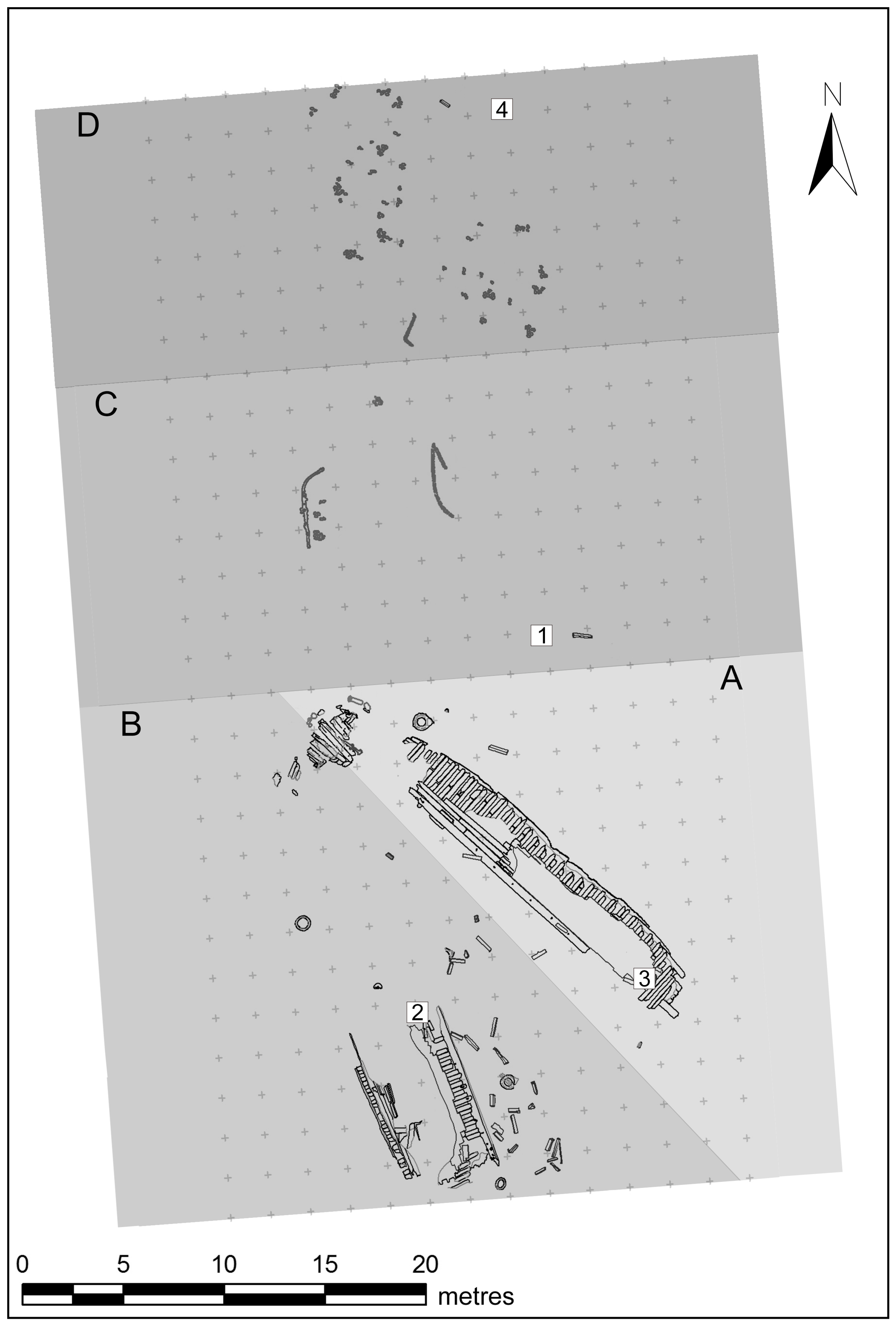
For the present study, four different specimens were selected from the Infatigable site iron ballast assemblage (Figure 4). Ballast No. 1 was retrieved during test excavations of the site conducted in 2006 in area C, immediately north of the starboard side hull structure. By contrast, ballasts Nos. 2, 3 and 4 were specifically recovered for metallurgical examination during the monitoring of the site in 2017. Ballast No. 2 was recovered in area B, within the port side hull structure and Ballast No. 3 in area A, abaft of the starboard side hull structure. Conversely, Ballast No. 4 was retrieved in area D, north of the hull structure and only associated with superficial deposits comprising small artefacts and ballast stones. Subsequent to in situ archaeological documentation—including a comprehensive survey and high-resolution underwater photographs—ballast blocks were recovered through diving operations using lifting bags.
Samples were sectioned using the combination of a disc-cutting machine and a water jet cutter. While ballasts Nos. 2 and 3 were returned to their original position at the site, Ballast No. 4 underwent conservation treatment and was added to the Infatigable archaeological collection.

3.2. Microstructural Characterisation and Chemical Analyses

Metallographic examination of the ballast samples was undertaken at the metallurgy and materials lab in the Department of Metallurgical Engineering at the Universidad de Santiago de Chile (LIMM-USACH) and involved several scientific methods, including both non-invasive and destructive testing. Microstructural features were examined using light microscopy (LM) and scanning electron microscopy (SEM) with secondary electron (SE) and backscattered electron (BSE) signals. Samples were sectioned with a cut-off machine and specimens were mounted in epoxy resin. Sample preparation was performed following ASTM specifications [79]. Unetched surfaces were observed at the optical microscope after polishing. Subsequently, samples were etched with Nital 2% for microstructural characterisation. A Zeiss Axiotech optical microscope and a Tescan VEGA3 (tungsten filament) scanning electron microscope were employed. For SEM-EDS analysis, the surface of specimens was covered by a thin layer of Au-Pd and analysed according to ASTM standards [80].
A combination of methods was used to determine the major and minor elements present in the alloy of the sampled ingots, including wavelength X-ray fluorescence (WD-XRF) and inert gas fusion (IGF) technique, the latter for determining carbon and sulphur content. Additionally, to analyse the microconstituents present in the alloy, energy-dispersive X-ray spectroscopy (EDS) was applied. The instrumentation used in each case was as follows: WD-XRF spectrometer Siemens SRS3000; inert gas fusion elemental analyser LECO 744; and the cited SEM coupled with an EDS Bruker Quantax xFlash 6 analyser. In each case, the followed standards were WD-XRF [81], IGF [82], and SEM-EDS [80].
Before analysis, the surface of the samples was subjected to a grinding and polishing process, as indicated above. The remaining corrosion was eliminated by chemical decoupage. Analyses were conducted at room temperature (25 °C). For WD-XRF and IGF, SRM C1137a and NIST2160 patterns were used, respectively. Each sample was tested at three points, and the mean of values obtained is reported herein. For XRF measurements, a 10 × 10 mm area was scanned, with an acquisition time of 420 s per scan.

4. Results

4.1. Macroscopic Study

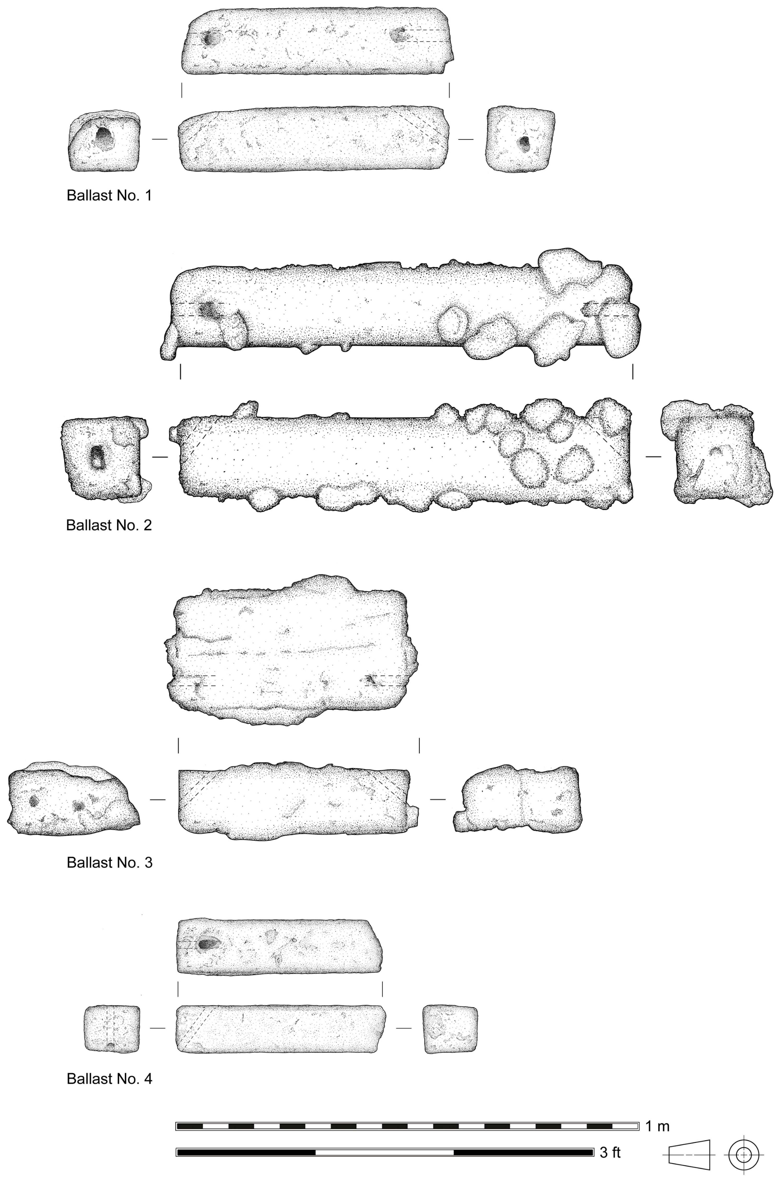
Archaeological documentation of the selected ballast specimens retrieved from Infatigable for sampling revealed that these correspond to parallelepiped iron blocks of various sizes (Figure 5). Relevant information about these artefacts is summarised in Table 1.
Ballast No. 1 is approximately 59 cm, long, 14 cm wide, and 14 cm thick and weighs 72 kg. It exhibits crudely manufactured cast diagonal channel holes on each end, connecting the lateral and superior faces. No marks were observed. Iron ballast of relatively similar shape and size was found at the wreckage of Frolic, an American clipper bound for Gold-Rush San Francisco from China and lost off the coast of California in 1850 [59] (pp. 22 & 39–40).
Ballast No. 2 is approximately 91 cm long, 15 cm wide, and 15 cm thick and weighs 140 kg. It exhibits diagonal channel holes on both ends, with no visible marks. Abundant shingle ballast stones (cobbles) and other materials were recorded concreted to the external corrosion layer. Its shape, dimensions, and weight are in good agreement with the largest of iron ballast pigs described by British mid-19th century sources: these were 3 feet long, 6 inches square, weighted 2 cwt, 3 qrs, 12 lbs, and calculated as 7 to a ton [83] (p. 83); [84] (p. 81). In addition, this iron ballast format has been extensively recorded within wreck sites of 18th-century British warships investigated archaeologically [44] (pp. 111–114); [46,66] (pp. 76–78).
When examined, Ballast No. 3 was revealed to be composed of two single blocks of similar size, concreted along their longitudinal axes. One of the blocks exhibits apparent signs of deterioration. The best preserved is approximately 46 cm long, 11.5 wide, and 11.5 cm thick. Since the concreted blocks weigh 60.8 kg, it can only be roughly inferred that each piece should weigh approximately 30 kg. It exhibits a diagonal channel hole at least on one end.
Finally, Ballast No. 4 measures 41 cm long, 10.5 cm wide, and 11 cm thick and weighs 33.7 kg. Only one end exhibits a diagonal channel hole. The opposite end has presumably broken off. Interestingly, during the deconcretion process, the remains of a flat, thin piece of wood were revealed adhered to the inferior face of the block, approximately perpendicular to the longitudinal axis. This evidence is consistent with the practice of installing strips of boards or hoop poles as dunnage athwart ship beneath the ballast to prevent damage to the floor timbers of the hull [41] (pp. 127–128); [85] (p. 137).

4.2. Microstructural and Chemical Features

Metallurgical examination of the sampled ingots indicates that all four pieces are in the as-cast condition. WD-XRF and IGF data revealed that all samples have a carbon content of >2.5 wt%, with the presence of silicon, phosphorous, and manganese in different amounts. The content of major and minor elements of the iron-carbon alloy of samples are reported in Table 2.
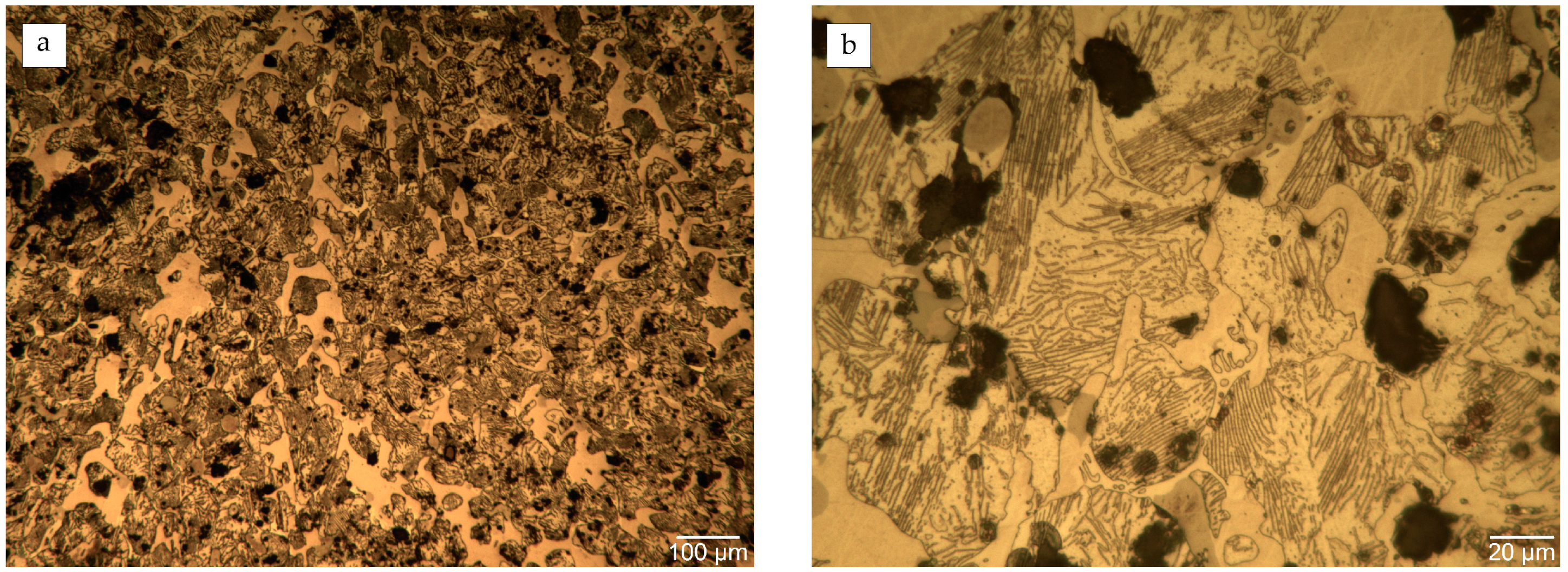
Based on metallographic observation of samples using LM, two main types of cast iron alloys were identified. Sample Nos. 1 and 2 display a microstructure of white cast iron, while samples Nos. 3 and 4 correspond to mottled cast iron.
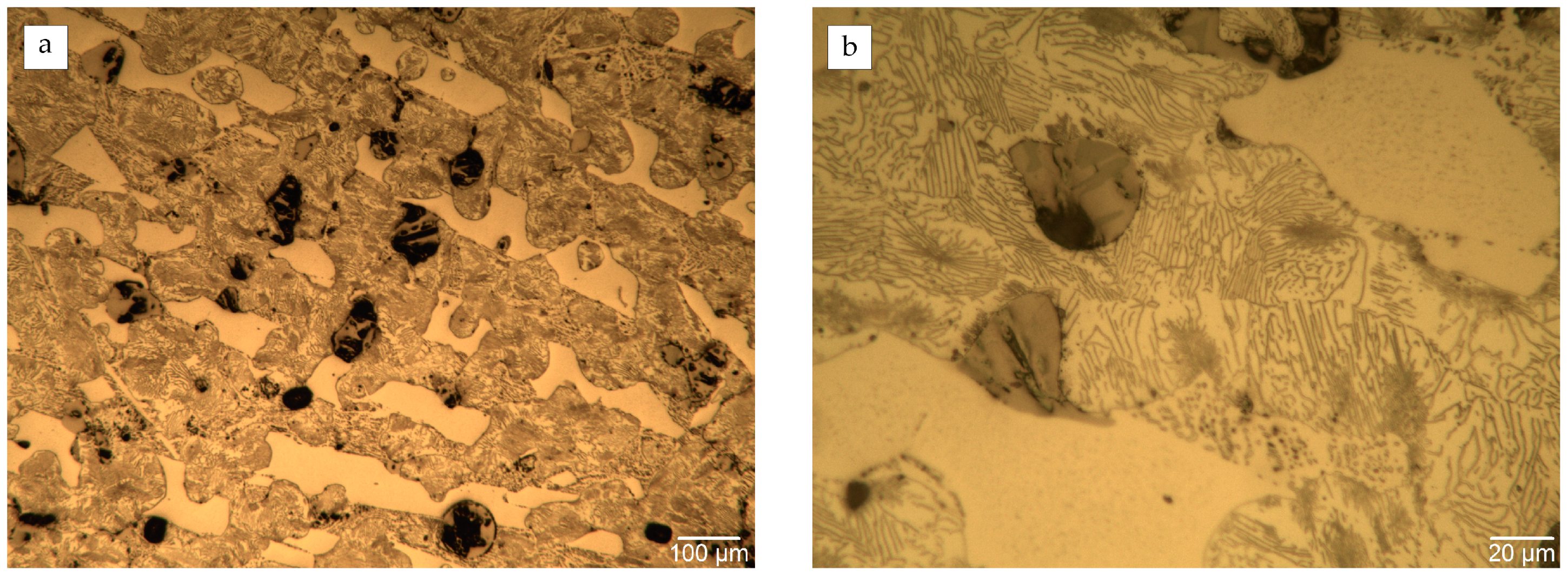
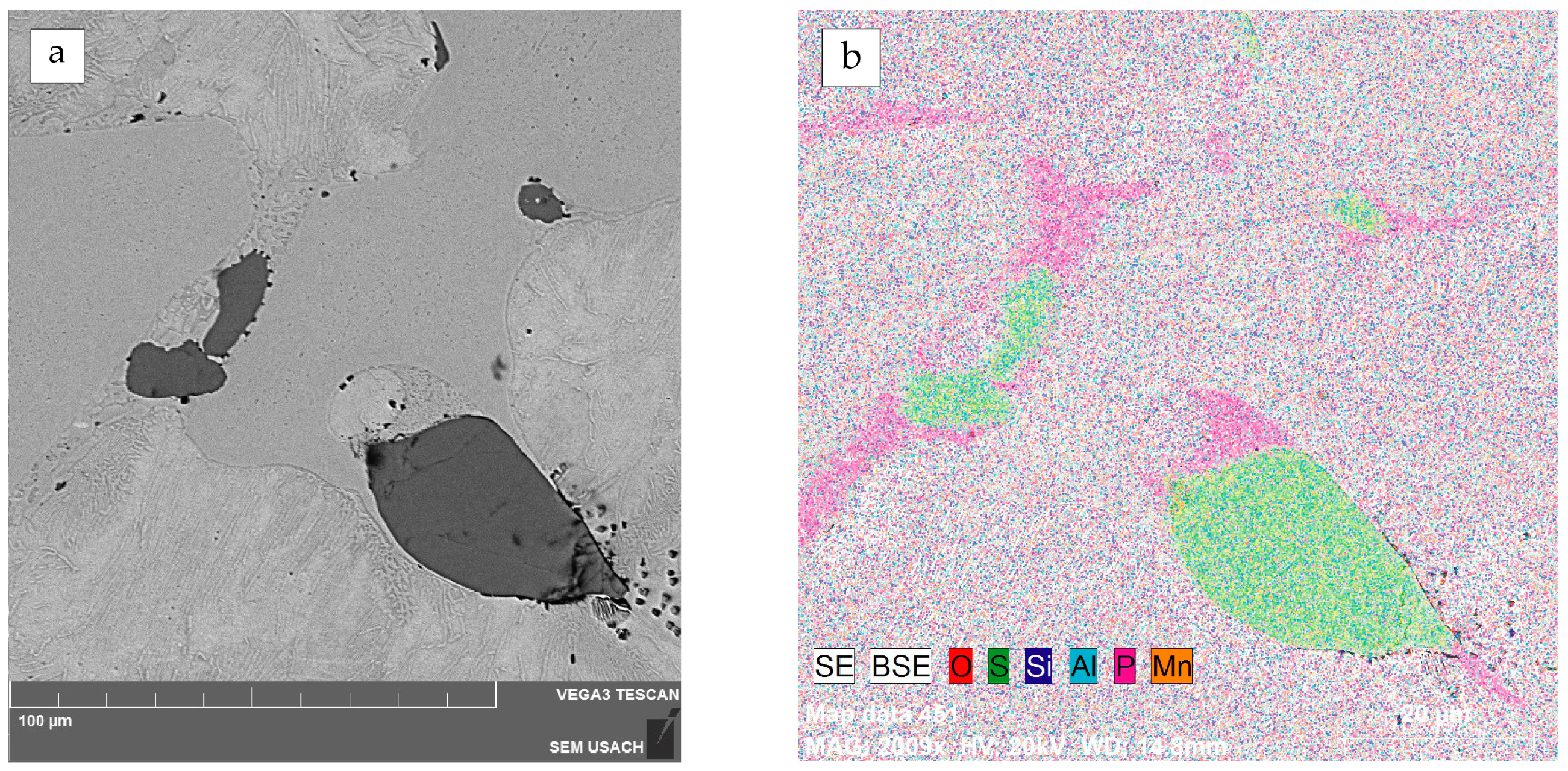
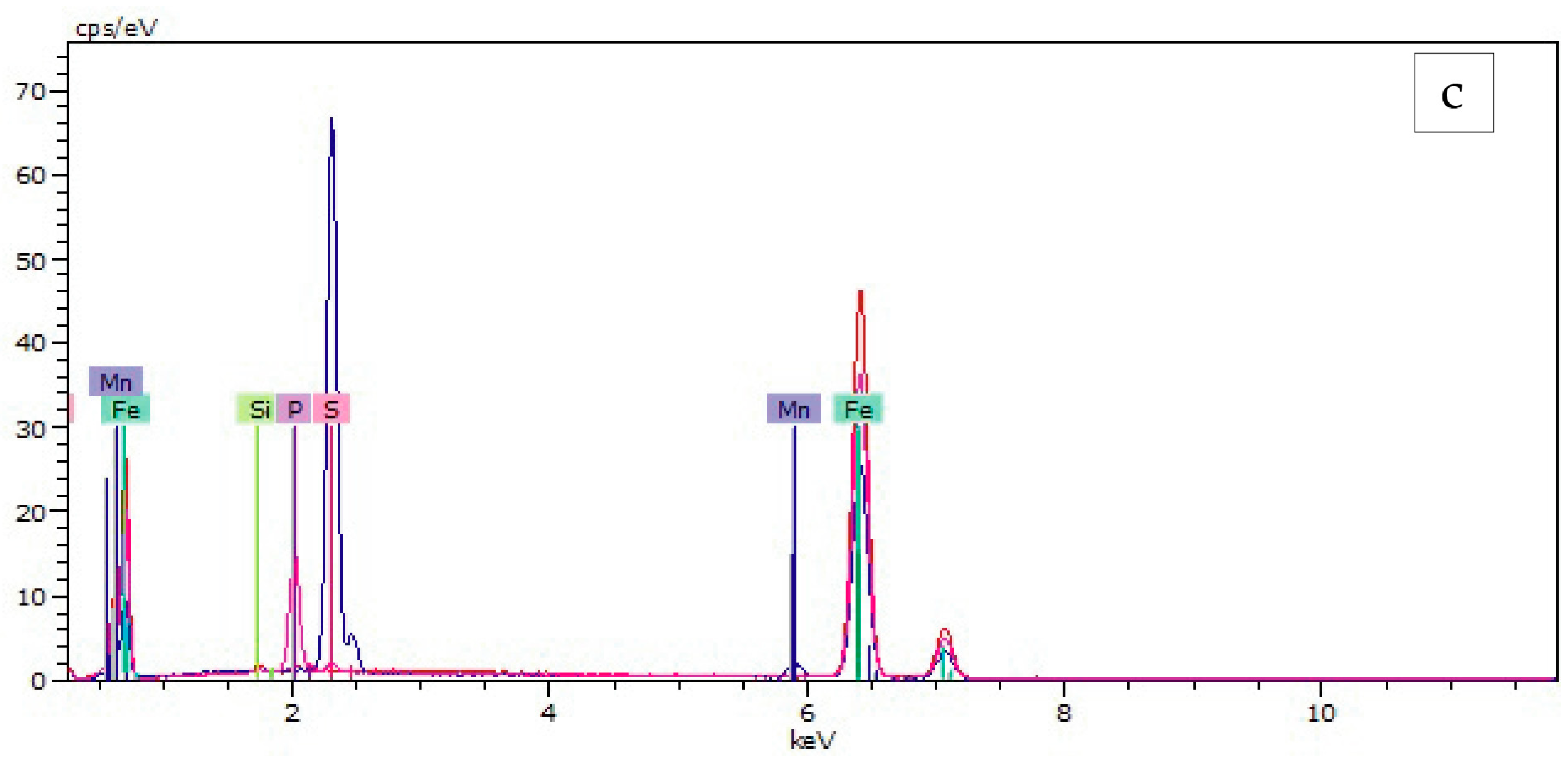
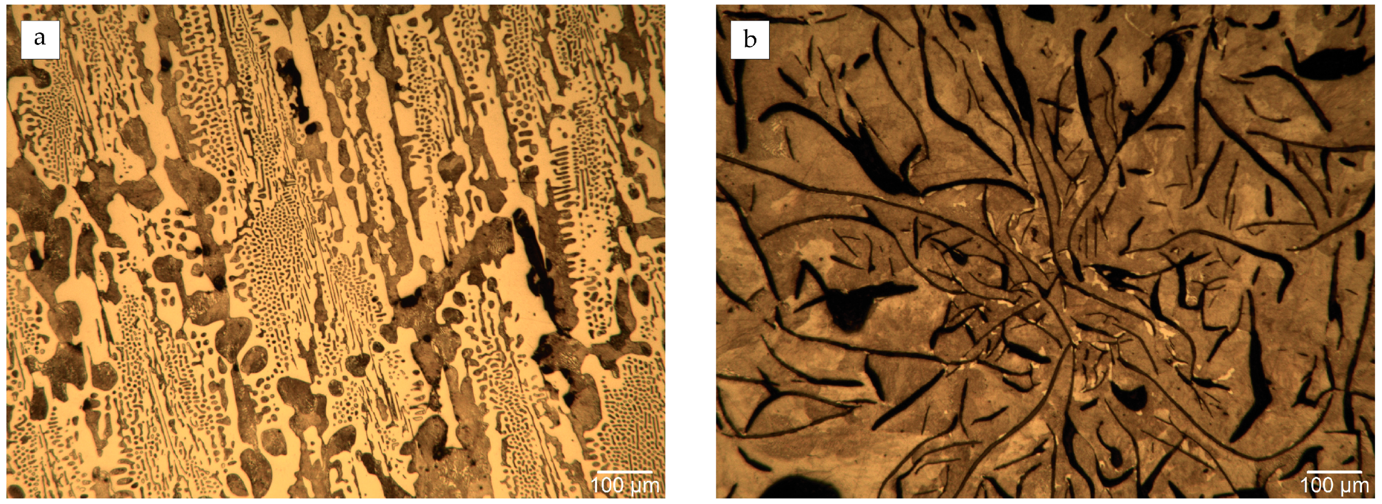
The microstructure of Sample No. 1 consists of a pearlite matrix (a two-phased, lamellar structure formed by crystals of ferrite and cementite) with cementite (iron carbide, Fe3C) (Figure 6). SEM-EDS mapping also revealed, on one hand, the presence of steadite (eutectic of ferrite, iron phosphide, and cementite, α-Fe + Fe3P + Fe3C), a microconstituent of high-phosphorus cast iron; and on the other, that the non-metallic inclusions previously observed with LM correspond to manganese sulphides (MnS) (Figure 7). Iron phosphides were not observed in the photomicrographs but were detected through SEM-EDS mapping (Figure 8). Micro-shrinkages related to the solidification process were also observed in some parts of the sample.
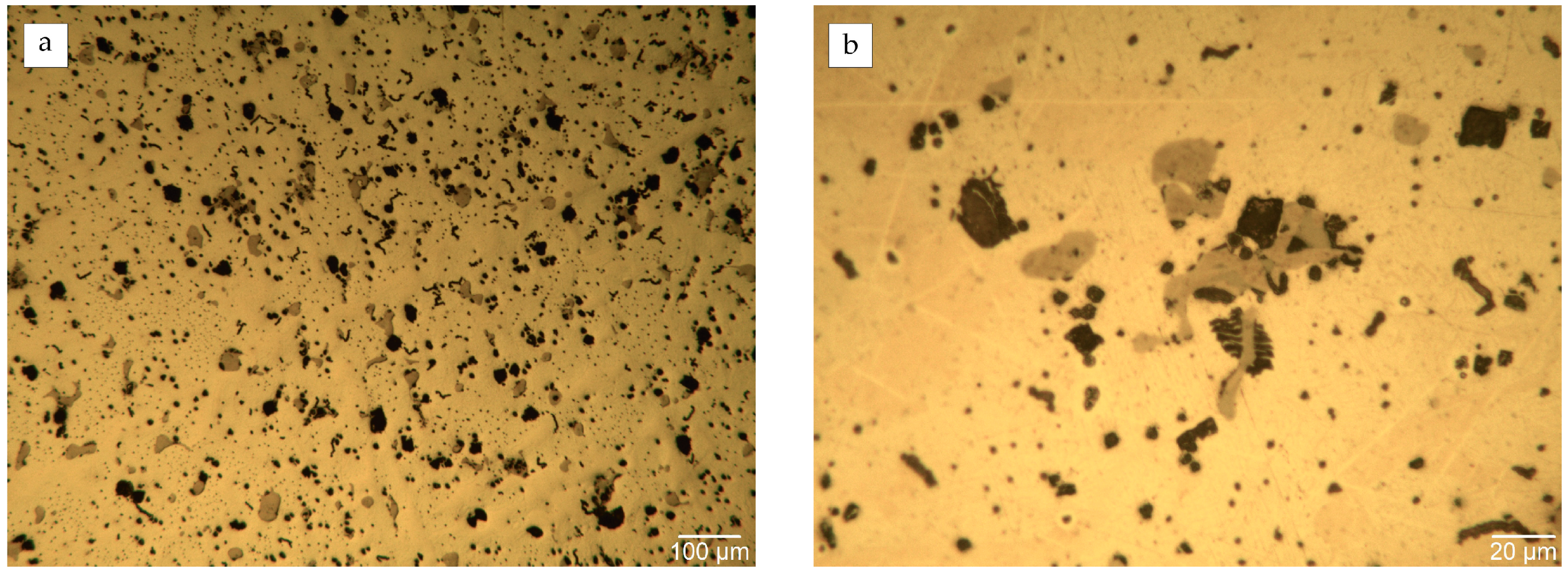
Sample No. 2 presents similar microstructural features to Sample No. 1 (Figure 9). This sample also exhibits a high amount of inclusions of MnS (Figure 10 and Figure 11).
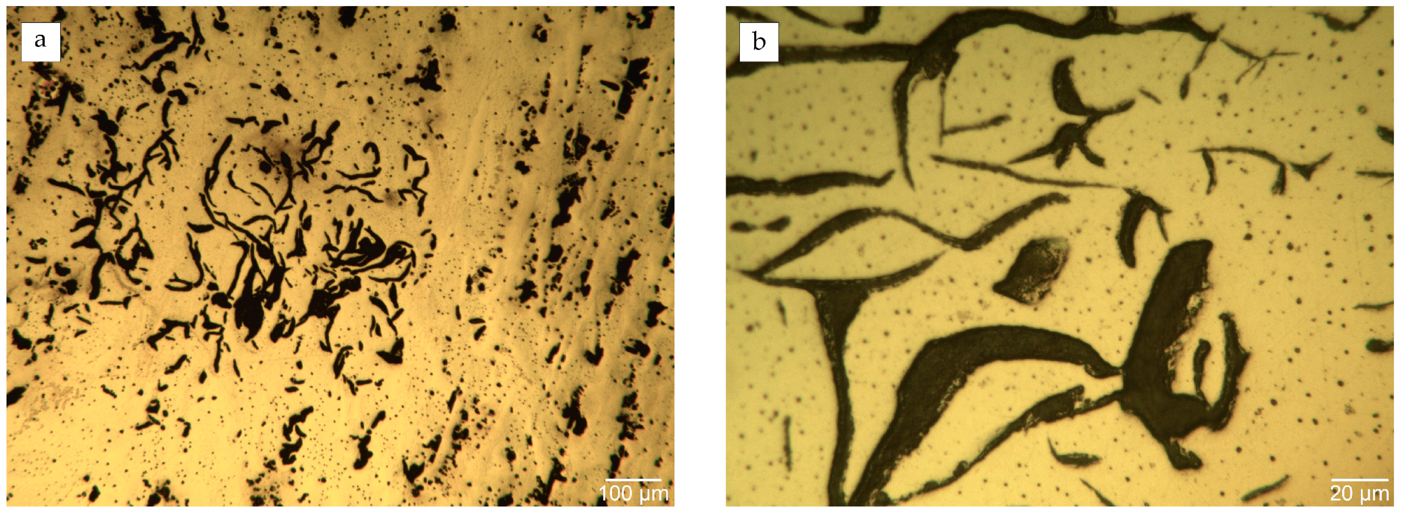
In contrast, both samples Nos. 3 and 4 exhibit a pearlite matrix with a significant amount of free carbon within the microstructure, observed both as laminar and interdendritic graphite corresponding to types A, C, and E, respectively (Figure 12, Figure 13, Figure 14 and Figure 15). The content of graphite type A in Sample No. 4 is notably higher than in Sample No. 3. Moreover, cementite was recorded in both samples, primarily associated with areas exhibiting interdendritic graphite (Figure 14 and Figure 16).
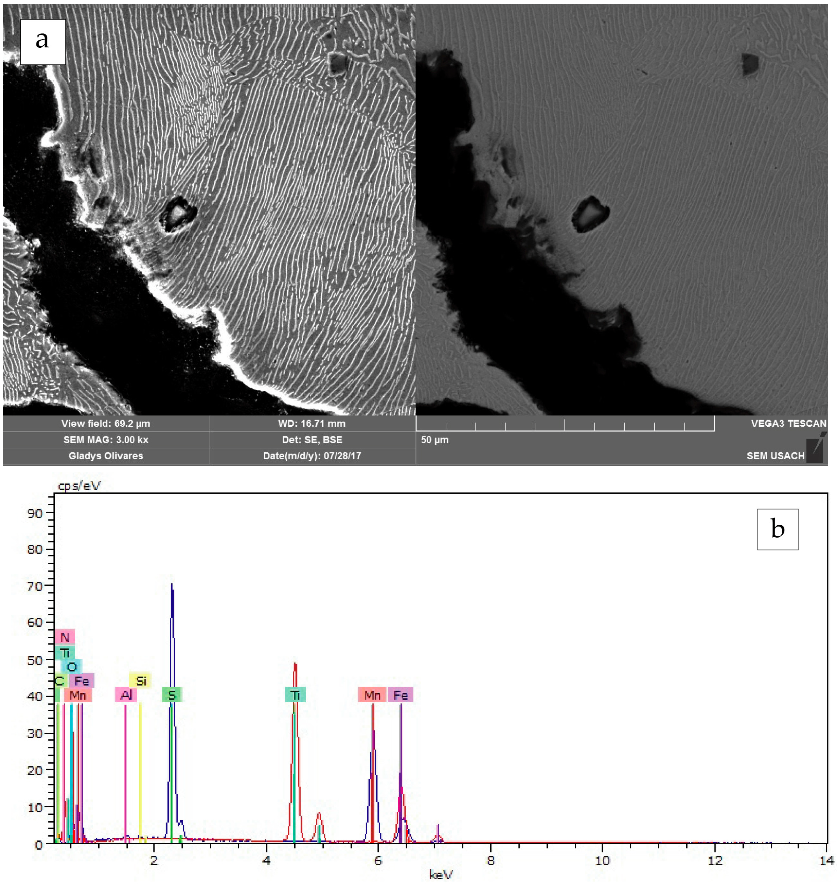
Both sample Nos. 3 and 4 show MnS inclusions, and titanium nitrides (TiN) were also noticed in the latter specimen. The very limited presence of phosphorous compounds was observed in Sample No. 3, while this element was not detected in Sample No. 4 (Figure 17 and Figure 18).

5. Discussion

The archaeological investigation of the Infatigable wreck site demonstrates that the well-documented practice of combining iron and shingle ballast on board sailing vessels was employed by the Chilean Navy by the mid-19th century. A single layer of pigs can be observed running fore and aft parallel to the keelson, without evidence of blocks running athwartships. No evidence of methods to secure the ballast in place has been observed so far. On the more heavily exposed starboard side of the hull, most of the remaining ballast lies stacked aft, where the pump well would have been located, with ingots lying only centimetres from the keelson, thus leaving no access to the limber boards. However, this observable distribution of ballast might be influenced by the complex site formation processes which have affected the site [86], and possible interpretations should be approached with caution.
The macroscopic study of selected ballast specimens revealed that these correspond to parallelepiped iron blocks of various sizes, cast with a diagonal channel hole on each end. These holes were intended to aid the lifting and transportation of the pieces, as already reported [59] (pp. 39–40); [64] (p. 104). In particular, Ballast No. 2, retrieved close to the centre of the hull in area B, is consistent in terms of weight and dimensions with the largest pigs of iron described by British sources of the period. It should further be noted that Ballast Nos. 3 and 4, retrieved in areas A and D, respectively, the smaller two and of similar size, likely correspond to material related to the stern of the vessel [86]. In addition, while pigs were observed deposited directly over the floor timbers of the hold, remains of a thin, flat piece of wood adhered to the inferior face of Ballast No 4 may indicate some type of dunnage to prevent damage to the hull.
Iron-carbon alloys recorded in the ingots sampled from Infatigable correspond to white and mottled cast iron. This type of material corresponds to an intermediate product generally known as pig iron, which was poured into moulds directly from the cupola furnace. As previously mentioned, the varying degree of graphitization (i.e., formation of graphite during solidification) of the analysed samples is associated with both composition and solidification rate, resulting in pieces of different quality. A comparison between pieces can be established based on the cast iron carbon equivalent (CE), using the following formula [70] (p. 331):
CE   wt % = C + 1 3 Si
where C is carbon and Si is silicon, the latter being the main element that promotes the reaction of cementite decomposition and free graphite formation during solidification [71] (p. 335). It should be noted that other authors also consider the phosphorus content in the formula, which is added to the silicon percentage [72] (p. 38); [87]. In general, a high CE and low cooling rate favour the formation of grey cast iron, while a low CE and a high cooling rate tend to produce white or mottled cast iron. Sample Nos. 1 and 2 have a CE of ca. 2.6% (ca. 3, if the content of phosphorous is considered), while in the case of specimen Nos. 3 and 4, this factor falls between ca. 3.7 to 3.9%. All samples are within the range of hypoeutectic cast iron (<4.3 wt%). In comparison, at a slow cooling rate, the last two would be more prone to solidify as grey cast iron.
Regarding other minor elements in the iron-carbon-silicon alloys, manganese stabilises cementite, as well as sulphur. Nonetheless, given their strong affinity, when both are present, they mix, forming MnS particles, with no significant influence on carbon [72] (p. 37). Thus, this element counteracts the detrimental effects that sulphur, probably deriving from iron ores, usually has on the mechanical properties of iron products [66] (pp. 76–77). The high manganese content detected in at least three samples—and most likely the fourth, as well—can be understood as an intentional addition to the alloy. As a regular practice in the modern iron industry, the use of manganese as a deoxidizer, and to counteract the disadvantageous effects of sulphur in the alloy, can be related to the patent of Josiah Heath (1839), which is why the presence of Mn in iron samples has been considered as a terminus post quem of about 1840 [88].
Additionally, phosphorus chemically promotes the formation of the metastable system, yet its presence in the alloy tends to produce the ternary phosphide eutectic known as steadite. This was the last constituent to solidify, given its low melting point (960 °C), resulting in both austenite (γ-Fe) and cementite solidifying slowly and allowing silicon (when present) to promote the graphitization process [72] (pp. 37–38). Both samples Nos. 1 and 2 have a significant amount of phosphorus (>1 wt%), although the low silicon content (<0.5 wt%) would have been insufficient to promote graphite formation in the solidification conditions experienced by both ingots.
Thus far, the microstructural and compositional data obtained from the sampled kentledge of Infatigable allows us to group specimens into at least two categories: white and mottled cast iron. The composition of samples (primarily, their CE) and the variables involved during the casting process (e.g., pouring temperature and solidification rate) were determinants in the products obtained. Despite their differences, and considering the commercial classification of the time, all four pieces occupy a lower position in terms of quality. The use of low-quality pig iron for ships’ ballast is not unexpected, as white cast iron ingots were easier to produce, cheaper, and heavier than those manufactured in grey cast iron. Therefore, for ballasting purposes only, grey cast iron would have provided no significant advantage over white cast iron.
While the composition of some ingots could eventually result in the attribution of a specific provenance, it was not possible to establish a direct correspondence between the analysed samples from Infatigable and the available records regarding the composition of coeval cast iron ingots from different places [74] (pp. 234–235); [76] (pp. 275–279); [77] (p. 63). However, the correspondence between the physicochemical characteristics of the investigated samples and the classification and compositional quantitative data provided by Turner [89] (pp. 212–213), even if not conclusive, suggests that the variability recorded in samples from the wreck site can attest to the use of dissimilar raw materials (minerals, fuel) and/or production in different foundries. As a step forward, the development of a broader database seems a useful path for assessing regularities and laying the groundwork for identifying possible compositional signatures.

6. Conclusions

The use of pig iron as ballast for ships is widely recorded by documentary sources and archaeological evidence from the period. Notwithstanding their importance for the stability and seaworthiness of naval and merchant vessels, with very rare exceptions, no detailed examination of these common finds, either their macrostructural features or their microstructural and compositional characteristics, has been undertaken to date.
In this paper, an analysis of pieces from the Chilean Navy barque Infatigable (1855) was conducted, following an interdisciplinary approach to better understand the materials used in an armed transport operating for a developing South American navy in the early post-independence period. Furthermore, this research strategy allowed us to address aspects related to mid-19th-century metallurgical practice, with a focus on the materials, knowledge, and techniques associated with the production of pig iron.
A combination of LM, SEM-EDS, XRF, and IGF techniques provided a glimpse into the different microstructures and compositions of the pieces. These data attest to the use of heterogeneous raw materials, which were subjected to different solidification rates after the molten metal was poured into moulds. This variability is also well reflected in their dimensional features, especially if Ballast Nos. 1 to 3 are compared with Ballast No. 4. Available data may suggest, in this venue, that these ingots were made in different production centres, but further analyses are needed to better assess this possibility.
The use of ingots with heterogeneous characteristics would not have been unusual in the historical context of Infatigable (1855), given the ship’s original provenance, its purpose/function, and supply constraints related to its operation in Chilean Patagonia and the Magellan Strait, all of which could have led to several ballast loading and unloading events. Extending this kind of study to other wreck sites of the period will provide not only further specific data to better understand this largely neglected but significant component of ships’ technology but also a more comprehensive panorama for addressing the production processes and changes in iron foundries during industrialisation.

Author Contributions

Project leader, funding acquisition, investigation, interpretation of archaeological data, writing—original draft preparation, writing—review and editing, D.C.; conceptualisation, bibliography survey, investigation, interpretation of analytical data, writing—original draft preparation, writing—review and editing, N.C.C.; formal analysis, interpretation of analytical data, C.A.; stabilisation of ingots and sampling, C.M.; methodology, supervision of LM, SEM-EDS, XRF, IGF analyses, F.G. All authors have read and agreed to the published version of the manuscript.

Funding

This work was supported by the National Agency of Research and Development (ANID)—Millennium Science Initiative Program (NCS2021_040).

Institutional Review Board Statement

Not applicable.

Informed Consent Statement

Not applicable.

Data Availability Statement

Data not included are available from the corresponding author upon reasonable request.

Acknowledgments

The authors would like to thank Ana Crespo-Solana and Tânia Manuel Casimiro for their invitation to contribute to this thematic volume. Research at the Infatigable wreck site has been conducted by ÀRKA-Maritime Archaeology, with the financial support of TPS Valparaiso S.A. (TPS). Thanks are due to Francisca Morales and Cristián Campos for providing drawings and illustrations, David Letelier for processing underwater photographs, and Diego Rojas for assisting with laboratory artefact handling and recording. Finally, we wish to thank the four anonymous reviewers for their constructive comments, which helped improve the paper.

Conflicts of Interest

The authors declare no conflict of interest. Moreover, the funders had no role in the design of the study; in the collection, analysis, or interpretation of data; in the writing of the manuscript; or in the decision to publish the results.

References

  1. Gifford, M.J. Everything Is Ballast: An Examination of Ballast Related Practices and Ballast Stones from the Emanuel Point Shipwrecks. Unpublished Master’s Thesis, The University of West Florida, Pensacola, FL, USA, 2014. Available online: https://www.academia.edu/8244906/Everything_is_Ballast_An_Examination_of_Ballast_Related_Practices_and_Ballast_from_the_Emanuel_Point_Shipwrecks (accessed on 30 September 2022).
  2. Keith, D.H.; Simmons, J.J. Analysis of hull remains, ballast, and artifact distribution of a 16th-century shipwreck, Molasses Reef, British West Indies. J. Field Archaeol. 1985, 12, 411–424. [Google Scholar] [CrossRef]
  3. Herrera, J.M. Ballast in the Port of Veracruz during the Second Half of the Eighteenth Century. In Underwater Archaeology; Lakey, D.A., Ed.; Society for Historical Archaeology: Uniontown, PA, USA, 1997; pp. 22–26. [Google Scholar]
  4. Villegas, T. El lastre en las naves europeas destinadas a América durante los siglos XVI y XVII. In Memorias del Congreso Científico de Arqueología Subacuática ICOMOS.; Erreguerena, P.L., Roffiel, R., Eds.; Instituto Nacional de Antropología e Historia: Mexico City, Mexico, 2001; pp. 131–142. [Google Scholar]
  5. Murray, C.; Vainstub, D.; Manders, M.; Bastida, R. El naufragio del Hoorn-1615-Prospecciones costeras y subacuáticas en la Ría Deseado (Santa Cruz-Argentina). In Arqueología de Fuego-Patagonia. Levantando Piedras, Desenterrando Huesos… y Develando Arcanos; Morello, F., Prieto, A., Martinic, M., Bahamondes, G., Eds.; Ediciones CEQUA: Punta Arenas, Chile, 2007; pp. 351–355. [Google Scholar]
  6. L’Hour, M.; Veyrat, E. A mid-15th century clinker boat off the north coast of France, the Aber Wrac’h I wreck: A preliminary report. Int. J. Naut. Archaeol. Underw. Explor. 1989, 18, 285–298. [Google Scholar] [CrossRef]
  7. Ciarlo, N.C.; Carrillo Márquez, L.; López Martín, S.J.; Zuccolotto Villalobos, A.; Guzmán Torres, J.; Pérez Morales, E.; Brown, R.R.; López Garrido, P.H. Revisitando el sitio 40 Cañones: Investigación arqueológica y documental de un naufragio del siglo XVII, Banco Chinchorro, México. In I Congreso Iberoamericano de Arqueología Náutica y Subacuática; University of Cadiz: Cadiz, Spain, 2022; in press. [Google Scholar]
  8. Garrison, E.G.; Giammona, C.P.; Jobling, J.; Tripp, A.R.; Weinstein, E.N.; Wolff, G.A. An Eighteenth-Century Ballast Pile Site, Chandeleur Islands, Louisiana. An Instrumental and Archaeological Study; OCS Study/MMS 89-0092; U.S. Department of the Interior, Minerals Management Service, Gulf of Mexico OCS Regional Office: New Orleans, LA, USA, 1989. Available online: https://espis.boem.gov/final%20reports/3689.pdf (accessed on 30 September 2022).
  9. L’Hour, M.; Veyrat, E. Un Corsaire Sous la Mer. Les Epaves de la Natière, Archéologie Sous-Marine à Saint-Malo; Edition Adramar: Saint-Malo, France, 2002. [Google Scholar]
  10. Lamb, W.R. The Provenance of the Stone Ballast from the Molasses Reef Wreck. Unpublished Master’s Thesis, Texas A&M University, College Station, TX, USA, 1988. Available online: https://nautarch.tamu.edu/Theses/pdf-files/Lamb-MA1988.pdf (accessed on 30 September 2022).
  11. Guérout, M.; Rieth, E.; Gassend, J.-M.; Liou, B. Le navire Génois de Villefranche, un naufrage de 1516? Archaeonautica 1989, 9, 5–171. [Google Scholar] [CrossRef]
  12. Van Duivenvoorde, W.; Stedman, J.; Billström, K.; Stos-Gale, Z.A.; McCarthy, M. The Lead Ingots from the Wreck of the Zuiddorp (1712), Western Australia: A report on their provenance and manufacture. Int. J. Naut. Archaeol. 2013, 42, 150–166. [Google Scholar] [CrossRef]
  13. Brandl, M.; Martinez, M.M.; Hauzenberger, C.; Filzmoser, P.; Nymoen, P.; Mehler, N. A multi-technique analytical approach to sourcing Scandinavian flint: Provenance of ballast flint from the shipwreck “Leirvigen 1”, Norway. PLoS ONE 2018, 13, e0200647. [Google Scholar] [CrossRef] [Green Version]
  14. Weissel, M.; Garberoglio, R.M.; Padula, H. Corals Used as Ballast: The Zen City Site, an 18th Century Shipwreck Found at Buenos Aires City, Argentina. 2021. Available online: http://socarchsci.blogspot.com/2021/08/corals-used-as-ballast-zen-city-site.html (accessed on 30 September 2022).
  15. Carabias, D. Valparaíso. El Patrimonio Bajo la Cota Cero del Puerto Principal. Revista Cultura y Desarrollo 13, 34-39. Patrimonio Cultural Subacuático en América Latina y El Caribe; UNESCO, Oficina Regional de Cultura para América Latina y el Caribe: La Habana, Cube, 2015. [Google Scholar]
  16. Carabias, D.; Simonetti, R.; Morales, C. Exploring Infatigable (1855): First Insights from Archaeology into the Mid-Nineteenth Century Chilean Navy; Society for Historical Archaeology Conference: New Orleans, LA, USA, 2018. [Google Scholar]
  17. Falconer, W. An Universal Dictionary of the Marine; T. Cadell: London, UK, 1780. [Google Scholar]
  18. Moore, L.L. The British Mariner’s Vocabulary; J. Cundee: London, UK, 1801. [Google Scholar]
  19. Steel, D. The Shipwright’s Vade-Mecum: A Clear and Familiar Introduction to the Principles and Practice of Ship-Building; P. Steel: London, UK, 1805. [Google Scholar]
  20. Meade, R.W. A Treatise on Naval Architecture and Ship-Building; J.B. Lippincott & Co.: Philadelphia, PA, USA, 1869. [Google Scholar]
  21. O’Scanlan, T. Diccionario Marítimo Español; Imprenta Real: Madrid, Spain, 1831. [Google Scholar]
  22. De Lorenzo, J.; De Murga, G.; Ferreiro, M. Diccionario Marítimo Español; Establecimiento Tipográfico de T. Fortanet: Madrid, Spain, 1854. [Google Scholar]
  23. Falconer, W.; Burney, W. A New Universal Dictionary of the Marine; Cadell and Davies: London, UK, 1815. [Google Scholar]
  24. O’Scanlan, T. Cartilla Práctica de Construcción Naval; Don Miguel de Burgos: Madrid, Spain, 1829. [Google Scholar]
  25. Feaser, E. HMS “VICTORY.” (Continued). Mar. Mirror 1922, 8, 259–264. [Google Scholar] [CrossRef]
  26. Harvey, A.D. Collision of Empires: Britain in Three World Wars, 1793–1945; Hambledon Press: London, UK, 1922. [Google Scholar]
  27. Henderson, G.; Klaka, K. Who or what sank HMS Sirius at Norfolk Island in 1790? Aust. Nav. Archit. 2019, 23, 38–39. [Google Scholar]
  28. Herrera, J.M.; Jiménez, P.; Pacheco Ruiz, R.; Blancas, J.; Ortiz Butrón, A.; Barba, L.; Vega Sánchez, R.; Arenas Cruz, M.; Mata, D.; Castillo Pérez, E.; et al. La memoria anfibia: Arqueología marítima de la Guerra entre México y los Estados Unidos, 1846–1848. In Arqueología en Campos de Batalla. América Latina en Perspectiva; Landa, C., Hernández de Lara, O., Eds.; Aspha: Buenos Aires, Argentina, 2020; pp. 63–116. [Google Scholar]
  29. Borrell, P.; Pérez Montás, E.; Apestegui, C. La Aventura del Guadalupe. Su viaje a La Española y su hundimiento en la Bahía de Samaná; Comisión de Rescate Arqueológico Submarino, CRAS: Lunwerg, Dominican Republic, 1997. [Google Scholar]
  30. Izaguirre, M. Pecios y materiales diversos de la bahía de La Concha (San Sebastián). In La Memoria Sumergida. Arqueología y Patrimonio Subacuático Vasco; Unsain, J.M., Ed.; Museo Naval: Donostia-San Sebastián, Spain, 2004; pp. 91–105. [Google Scholar]
  31. Maarleveld, T.; Overmeer, A.; Brinkkemper, O.; van Deijk, F.; Gijsbers, W.M.; Jacobs, E.M.; Joosten, C.; Terhorst, M.; Vos, A.D. Aanloop Molengat—Maritime archaeology and intermediate trade during the Thirty Years’ War. J. Archaeol. Low Ctries. 2012, 4, 95–149. [Google Scholar]
  32. Birch, T.; Charlton, M.F.; Biggs, L.; Stos-Gale, Z.A.; Martinón-Torres, M. The Cargo. In The Gresham Ship Project A 16th-Century Merchantman Wrecked in the Princes Channel, Thames Estuary; Milne, G., Sully, D., Eds.; British Archaeological Reports, British Series No. 606; Archaeopress: Oxford, UK, 2014; Volume 2, pp. 53–69. [Google Scholar]
  33. Green, J. The wreck of the Dutch East Indiaman the Vergulde Draeck, 1656. Int. J. Naut. Archaeol. Underw. Explor. 1973, 2, 267–289. [Google Scholar] [CrossRef]
  34. McGrail, S. The Shipment of Traded Goods and of Ballast in Antiquity. Oxf. J. Archaeol. 1989, 8, 353–358. [Google Scholar] [CrossRef]
  35. King, P.W. Pig iron ballast for the Georgian Navy and its producers. Mar. Mirror 1985, 81, 15–20. [Google Scholar] [CrossRef]
  36. Lavery, B. The Arming and Fitting of English Ships of War 1600−1815; Conway Maritime Press: London, UK, 1987. [Google Scholar]
  37. Steel, D. The Elements and Practice of Rigging And Seamanship; D. Steel: London, UK, 1794; Available online: https://maritime.org/doc/steel/ (accessed on 30 September 2022).
  38. Martínez de Espinosa y Tacón, J.J. Diccionario Marino Inglés-Español para el Uso del Colegio Naval; Imprenta de J. Martín Alegría: Madrid, Spain, 1849. [Google Scholar]
  39. Ciscar, F. Reflexiones Sobre las Máquinas y Maniobras Del uso de a Bordo; Imprenta Real: Madrid, Spain, 1791. [Google Scholar]
  40. González-Aller Hierro, J.I. La pérdida de la fragata Mercedes. In El último Viaje de la Fragata Mercedes. La Razón Frente al Expolio. Un Tesoro Cultural Recuperado; Museo Naval & Museo Arqueológico Nacional: Madrid, Spain, 2014; pp. 325–335. Available online: https://www.accioncultural.es/media/Default%20Files/activ/2015/pub/fragataMercedes/El-ultimo-viaje-de-la-Fragata-Mercedes.pdf (accessed on 30 September 2022).
  41. Brady, W. The Naval Apprentice’s Kedge Anchor; or Young Sailor’s Assistant; Taylor and Clement: New York, NY, USA, 1841. [Google Scholar]
  42. National Oceanic and Atmospheric Administration—NOAA (1980). Final environmental impact statement prepared on the proposed Looe Key National Marine Sanctuary. Charleston, SC: U.S. Department of Commerce, NOAA Office of Coastal Zone Management. Available online: https://repository.library.noaa.gov/view/noaa/1408 (accessed on 30 September 2022).
  43. Garrison, E.G. Recent Advances in Close Range Photogrammetry for Underwater Historical Archaeology. Hist. Archaeol. 1999, 26, 97–104. [Google Scholar] [CrossRef]
  44. Skowronek, R.K.; Fischer, G.R. HMS Fowey. Lost and Found. Being the Discovery, Excavation, and Identification of a British Man-of-War Lost off the Cape of Florida in 1748; University Press of Florida: Gainesville, FL, USA, 2019. [Google Scholar]
  45. Stanbury, M. Appendix 3. Sirius objects for Australian Bicentennial Authority Exhibition. In Australian Bicentennial Authority Project 1987. Expedition Report on the Wreck of HMS Sirius (1970); Department of Maritime Archaeology, Western Australian Maritime Museum, The Australian Bicentennial Authority: Sydney, Australia, 1988; pp. 31–38. [Google Scholar]
  46. Erskine, N. Reclaiming the Bounty. Archaeology 1999, 52. Available online: https://archive.archaeology.org/9905/etc/bounty.html (accessed on 30 September 2022).
  47. Flynn, P.E. HMS Pallas: Historical Reconstruction of an 18th-Century Royal Navy Frigate. Unpublished Master’s Thesis, Texas A&M University, College Station, TX, USA, 2006. Available online: https://www.nautarch.tamu.edu/academic/alum.htm (accessed on 30 September 2022).
  48. National Heritage List. HMS Sirius Shipwreck (file no. 9/00/001/0023). Australian Heritage Database, Department of Sustainability, Environment, Water, Population, and Communities, Government of Australia. 2020. Available online: https://www.dcceew.gov.au/sites/default/files/documents/sirius-final-assessment-report.pdf (accessed on 30 September 2022).
  49. San Claudio, M. La fragata de guerra Santa María Magdalena, lecciones para la gestión y preservación del Patrimonio Cultural Subacuático español. Proa Mar 2017, 172, 48–52. [Google Scholar]
  50. Mitchell, J. HMS Sirius Site Inspection Report; Prepared for the Department of Infrastructure, Transport, Regional Development and Communications; Cosmos Archaeology: Norfolk Island, Australia, 2021. Available online: https://kingston.norfolkisland.gov.au/sites/default/files/documents/hms-sirius-site-inspection-report-2020.pdf (accessed on 30 September 2022).
  51. Tomalin, D.; Simpson, P.; Bingeman, J.P. Excavation versus sustainability in situ: A conclusion on 25 years of archaeological investigations at Goose Rock, a designated historic wreck-site at the Needles, Isle of Wight, England. Int. J. Naut. Archaeol. 2000, 29, 3–42. [Google Scholar] [CrossRef]
  52. Beltrame, C.; Gaddi, D. Report on the first research campaign on the Napoleonic brick, Mercure, wrecked off Lignano, Udine, Italy in 1812. Int. J. Naut. Archaeol. 2002, 31, 60–73. [Google Scholar] [CrossRef]
  53. Guibert, J.-S. Results from the first excavation on the Saintes Bay’s Shipwreck, Guadeloupe, FWI. In ACUA Underwater Archaeology Proceedings; Johnston, P.F., Ed.; Advisory Council on Underwater Archaeology, Society for Historical Archaeology: Washington, DC, USA, 2016; pp. 65–70. Available online: https://hal.archives-ouvertes.fr/hal-01443277/document (accessed on 30 September 2022).
  54. Bingeman, J.M.; Simpson, P.; Tomalin, D. The Wrecks of HM Frigates Assurance (1753) and Pomone (1811); Oxbow Books: Oxford, UK, 2021. [Google Scholar]
  55. Bousquet, G.; L’Hour, M.; Richez, F. The discovery of an English East Indiaman at Bassas da india, a French atoll in the Indian Ocean: The Sussex (1738). Int. J. Naut. Archaeol. Underw. Explor. 1990, 19, 81–85. [Google Scholar] [CrossRef]
  56. L’Hour, M.; Richez, F. An 18th century French East Indiaman: The Prince de Conty (1746). Int. J. Naut. Archaeol. Underw. Explor. 1990, 19, 75–79. [Google Scholar] [CrossRef]
  57. Direction Générale des Patrimoines (DGP). Shipbuilding|The Structure of the Aimable Grenot: Ballast. Ministry of Culture, France. 2022. Available online: https://archeologie.culture.gouv.fr/epaves-corsaires/en/ballast-0 (accessed on 30 September 2022).
  58. Boshoff, J.J.; Bunch, L.G.; Gardullo, P.; Lubkemann, S.P. From no Return: The 221-Year Journey of the Slave Ship São José, 1794; Smithsonian, National Museum of African American History and Culture: Washington, DC, USA, 2016. [Google Scholar]
  59. Smith, S.O. The Frolic Archaeological Survey; California Department of Parks and Recreation, Cultural Heritage Division, PAST Foundation Publication: Columbus, OH, USA, 2005. [Google Scholar]
  60. Green, J. Shipwrecks of the Ningaloo Reef: Maritime Archaeological Projects from 1978–2009; Australian National Centre of Excellence for Maritime Archaeology, Special Publication No. 14; Western Australian Maritime Museum: Fremantle, Australia, 2011. Available online: https://museum.wa.gov.au/maritime-archaeology-db/sites/default/files/no._14_shipwrecks_of_ningaloo_reef.pdf (accessed on 30 September 2022).
  61. Van Tilburg, H. Historic period ships of the Pacific Ocean. In The Oxford Handbook of Maritime Archaeology; Oxford University Press: New York, NY, USA, 2011; pp. 588–609. [Google Scholar]
  62. Guérout, M.; Veccella, R.; Carabias, D. Fouille de l’épave du Francisco Álvarez à Mangareva et inventaire du patrimoine archéologique sous-marin de l’archipel des Gambier. Bull. De La Soc. D’études Océanniennes 2002, 292–293, 45–64. [Google Scholar]
  63. Gainsford, M. The Redemptora. Report. Department of Maritime Archaeology, Western Australian Maritime Museum No. 166. 2003. Available online: https://museum.wa.gov.au/maritime-archaeology-db/sites/default/files/no._166_redemptora_0.pdf (accessed on 30 September 2022).
  64. Schwalbe, E.A. Civil War and the H.L. Hunley iron Ballast. Ind. Archaeol. Rev. 2019, 41, 100–106. [Google Scholar] [CrossRef]
  65. Samuels, L.E. The metallography of cast iron relics from the Bark Endeavour. Metallography 1980, 13, 345–355. [Google Scholar] [CrossRef]
  66. Samuels, L.E. Australia’s Contribution to Archaeometallurgy. Mater. Charact. 1992, 29, 69–109. [Google Scholar] [CrossRef]
  67. Ciarlo, N.C.; Argüeso, A. Archaeometric and Archaeometallurgical Studies on Historical Shipwrecks: Research Experiences in Argentina. J. Marit. Archaeol. 2019, 14, 127–150. [Google Scholar] [CrossRef]
  68. Ciarlo, N.C. Historical Shipwrecks, Archaeometry of. In Encyclopedia of Global Archaeology, 2nd ed.; Smith, C., Ed.; Springer: Cham, Switzerland, 2020. [Google Scholar] [CrossRef]
  69. Ciarlo, N.C. Industrialisation, Warfare, and Science: An archaeological-historical insight into technological changes of mid-18th to early 19th-century European naval ships. Int. J. Naut. Archaeol. 2023. (Accepted for publication). [Google Scholar]
  70. Verhoeven, J.D. Fundamentos de Metalurgia Física; Editorial Limusa: México City, Mexico, 1987; (Original work published 1975). [Google Scholar]
  71. Callister, W.D., Jr.; Rethwisch, D.G. Material Science and Engineering. An Introduction, 9th ed.; Wiley: Hoboken, NJ, USA, 2014; (Original work published 1985). [Google Scholar]
  72. Scott, D.A. Metallography and Microstructure of Ancient and Historic Metals; Getty Conservation Institute in Association with Archetype Books: Marina del Rey, CA, USA, 1991; Available online: http://hdl.handle.net/10020/gci_pubs/metallography_microstructure (accessed on 30 September 2022).
  73. Baldwyn Rogers, S. An Elementary Treatise on Iron Metallurgy; Simpkin, Marshall, and Co., Stationers’ Hall Court, and The Mining Journal Office: London, UK, 1858. [Google Scholar]
  74. Bauerman, H. A Treatise on the Metallurgy of Iron; Virtue & Yorston: New York, NY, USA, 1868. [Google Scholar]
  75. Crookes, W.; Röhrig, E. Practical Treatise on Metallurgy; Longmans, Green, and Co.: London, UK, 1869. [Google Scholar]
  76. Fairbairn, W. Iron: Its History, Properties, & Processes of Manufacture; Adam and Charles Black: Edinburgh, UK, 1869. [Google Scholar]
  77. Greenwood, W.H. A Manual of Metallurgy; William Collins, Sons, & Company: London, UK, 1874. [Google Scholar]
  78. Bethencourt, M.; Hernández, M.A.; Martínez, E.A.; Abreu, C.M. Apuntes sobre la evolución histórica de la metalurgia armamentística española de los siglos XVII a XIX a través de la caracterización de balas de cañón. In IV Congreso Latinoamericano de Conservación y Restauración de Metal; Instituto del Patrimonio Cultural de España and Grupo Español de Conservación: Madrid, Spain, 2013; pp. 391–399. [Google Scholar]
  79. ASTM E3-11; Standard Guide for Preparation of Metallographic Specimens. ASTM International: Conshohocken, PA, USA, 2017. [CrossRef]
  80. ASTM E1508-12; Standard Guide for Quantitative Analysis by Energy-Dispersive Spectroscopy. ASTM International: Conshohocken, PA, USA, 2013. [CrossRef]
  81. ASTM E1621-13; Standard Guide for Elemental Analysis by Wavelength Dispersive X-Ray Fluorescence Spectrometry. ASTM International: Conshohocken, PA, USA, 2013. [CrossRef]
  82. ASTM E1019-11; Standard Test Methods for Determination of Carbon, Sulfur, Nitrogen, and Oxygen in Steel, Iron, Nickel, and Cobalt Alloys by Various Combustion and Fusion Techniques. ASTM International: Conshohocken, PA, USA, 2011. [CrossRef]
  83. Boyd, J.M. A Manual for Naval Cadets; Longmans, & Roberts: London, UK, 1857. [Google Scholar]
  84. Stevens, R.W. On the Stowage of Ships and Their Cargoes; Longman’s: London, UK, 1858. [Google Scholar]
  85. Totten, B.J. Naval Text-Book and Dictionary for the Use of the Midshipmen of the U.S. Navy; Van Nostrand: New York, NY, USA, 1862. [Google Scholar]
  86. Carabias, D.; Simonetti, R. Intrasite Spatial Analysis in Shipwreck Maritime Archaeology: The Infatigable Case Study, Valparaiso, Chile; International Congress of Underwater Archaeology: Helsinki, Finland, 2022. [Google Scholar]
  87. Föll, H. Kinds of Cast Iron. Kiel: Christian-Albrechts-Universität zu Kiel. 2022. Available online: https://www.tf.uni-kiel.de/matwis/amat/iss/index.html (accessed on 30 September 2022).
  88. Wiltzen, T.S.; Wayman, M.L. Steel files as chronological markers in North American fur trade sites. Archaeometry 1999, 41, 117–135. [Google Scholar] [CrossRef]
  89. Turner, T. The Metallurgy of Iron and Steel: Being One of A Series of Treatises on Metallurgy Written by Associates of the Royal School of Mines; Charles Griffin and Company, Ltd.: London, UK, 1895. [Google Scholar]
Figure 1. Map showing the location of the remains of the Chilean barque Infatigable (site S3 PV) in the inner harbour of Valparaiso, located on the central coast of Chile (33° S) (Illustration: Francisca Morales).
Heritage 06 00114 g001
Figure 2. Site plan of Infatigable highlighting iron and shingle ballast elements, 2009 survey. (a) Top view of a concreted layer of iron ballast blocks on the starboard side of the hull; and (b) lateral view of the same locus, featuring hull frames in the foreground and a concreted layer of blocks in the background (Drawing: Francisca Morales. Photographs: David Letelier).
Heritage 06 00114 g002
Figure 3. Diagram representing the typical stowage of iron and shingle ballast and casks (starboard side only) in the main hold of a vessel in the mid-19th century: top view (above) and cross section of the mid-ship area (below). (1) Iron ballast; (2) Shingle ballast; (3) Keelson; (4) Main mast step; (5) Cant to secure iron ballast; (6) Limber boards; (7) Fore bulkhead; (8) After hold bulkhead. The dark shaded area in the top view would be stowed with a second ‘tier’ of iron ballast on top of the first (Illustration: F. Morales. Adapted from Steel [37] (p. 286).
Heritage 06 00114 g003
Figure 4. Iron ballast blocks retrieved from Infatigable included in the present study (Nos. 1 to 4). Specimens were collected in areas, A, B, C, and D of the wreck site. The image depicts the 2017 site plan, when most of the samples were recovered (Illustration: Francisca Morales).
Heritage 06 00114 g004
Figure 5. Comparison of iron ballast blocks from Infatigable included in the present study (Illustration: Francisca Morales).
Heritage 06 00114 g005
Figure 6. Photomicrographs of Sample No. 1: (a) pearlite matrix (grey) with cementite (elongated white crystals); and (b) detail of the microconstituents mentioned, where alternated layers of ferrite and cementite (i.e., pearlite) can be observed. Magnification: 100× (a); and 500× (b). Etching: Nital 2%.
Heritage 06 00114 g006
Figure 7. Photomicrographs of the unetched polished surface of Sample No. 1, showing non-metallic inclusions of different sizes (a,b) identified as MnS particles (light grey). Magnification: 500×.
Heritage 06 00114 g007
Figure 8. SEM-EDS analysis of the alloy constituents of Sample No. 1: (a) SEM image (BSE); (b) EDS mapping of the area presented in (a) combining O, S, Si, Al, P, and Mn. MnS inclusions are seen in light green; in addition, the presence of iron phosphides is observed (light purple); and (c) EDS spectra of different microconstituents (blue spectrum corresponds to an MnS inclusion).
Heritage 06 00114 g008aHeritage 06 00114 g008b
Figure 9. Photomicrographs of Sample No. 2: (a) pearlite matrix (light grey) with cementite (white crystals); and (b) detail of the main microconstituents. Magnification: 100× (a); and 500× (b). Etching: Nital 2%.
Heritage 06 00114 g009
Figure 10. Photomicrographs of the unetched polished surface of Sample No. 2. A high amount of iron manganese sulphides (grey inclusions) can also be observed. Magnification: 100× (a); and 500× (b).
Heritage 06 00114 g010
Figure 11. SEM-EDS analysis of the alloy constituents of Sample No. 2: (a) SEM image (SE); (b) EDS mapping of the area presented in (a), where the MnS inclusions are seen in light green, and iron phosphides are in light purple; and (c) EDS spectra of inclusions (red spectrum corresponds to an MnS particle).
Heritage 06 00114 g011
Figure 12. Photomicrographs of the unetched polished surface of Sample No. 3, where lamellar graphite (type A & E) is shown. Magnification: 100× (a); and 500× (b).
Heritage 06 00114 g012
Figure 13. Photomicrographs of the unetched polished surface of Sample No. 4, where lamellar graphite (types A & C) is observed. Magnification: 100× (a); and 500× (b).
Heritage 06 00114 g013
Figure 14. Photomicrographs of Sample No. 3: (a) microstructure of pearlite (light grey) and cementite (elongated white crystals); and (b) detail of the lamellar graphite surrounded by a pearlite matrix. Magnification: 100× (a); and 500× (b). Etching: Nital 2%.
Heritage 06 00114 g014
Figure 15. Photomicrographs of Sample No. 3, showing an enlarged view of pearlite (grey lamellar structure) and cementite (white) phases. Magnification: 500× (a); and 1000× (b). Etching: Nital 2%.
Heritage 06 00114 g015
Figure 16. Photomicrographs of Sample No. 4: (a) microstructure of pearlite (light grey) and cementite (elongated white crystals); and (b) amplification of lamellar graphite surrounded by a pearlite matrix. Magnification: 100× (a); and 100× (b). Etching: Nital 2%.
Heritage 06 00114 g016
Figure 17. SEM-EDS analysis of the alloy constituents of Sample No. 3: (a) SEM image (SE); and (b) EDS mapping of the area presented in (a); and (c) EDS spectra of microconstituents (blue spectrum corresponds to an MnS particle).
Heritage 06 00114 g017
Figure 18. SEM-EDS analysis of the alloy constituents of Sample No. 4: (a) SEM images (SE & BSE); and (b) EDS spectra of MnS and TiN inclusions, which can be observed at the centre and top-right of (a), respectively.
Heritage 06 00114 g018
Table 1. Selected iron ballast blocks recorded.
ArtefactDimensions (cm)Weight (kg)Channel HolesMarksDescription
Ballast No. 159 × 14 × 1472Double-Single ballast block. Diagonal channel holes on each end.
Shingle ballast stones, fibres, and wood remains recovered during the deconcretion process.
Ballast No. 291 × 15 × 15140Double-Single ballast block. A diagonal channel hole is visible on one end, its opposite can be inferred. Abundant concreted shingle ballast stones and remains of wood were observed.
Ballast No. 3 146 × 11.5 × 11.560.8Single-Two ballast blocks of similar size concreted alongside, one visibly disintegrated. A diagonal channel hole is visible on one end.
Ballast No. 441 × 10.5 × 1133.7Single-Single ballast block. A diagonal channel hole is visible on one end; the opposite side is presumably fractured. Wood remains on the inferior face, possibly dunnage.
Note: 1 The dimensions and weight of this ballast were inferred from the best-preserved piece.
Table 2. Elemental composition of specimens (wt%), obtained by WD-XRF and IGF.
SampleFeCSiPMnAlS
No. 194.512.520.311.271.29n/d0.10
No. 294.272.580.141.151.280.420.16
No. 392.632.92.310.131.370.410.25
No. 495.293.890.150.040.45<0.010.01
Disclaimer/Publisher’s Note: The statements, opinions and data contained in all publications are solely those of the individual author(s) and contributor(s) and not of MDPI and/or the editor(s). MDPI and/or the editor(s) disclaim responsibility for any injury to people or property resulting from any ideas, methods, instructions or products referred to in the content.