Article

The Grouting Process as an Innovative Tool for the Assessment of the State of Preservation and Internal Features of the Holy Aedicule of the Holy Sepulchre

by
Kyriakos C. Lampropoulos
*,
Maria Apostolopoulou
,
Elisavet Tsilimantou
and
Antonia Moropoulou
School of Chemical Engineering, Section of Materials Science and Engineering, National Technical University of Athens, Iroon Polytechniou 9, 15780 Zografou, Greece
*
Author to whom correspondence should be addressed.
Heritage 2022, 5(1), 61-87; https://doi.org/10.3390/heritage5010004
Submission received: 11 November 2021 / Revised: 16 December 2021 / Accepted: 21 December 2021 / Published: 25 December 2021

Abstract

:
Grouting of historic structures is a common procedure in many restoration projects, as the masonry in many cases requires additional strengthening. However, grouting of complex historic structures can also provide important information regarding the construction phases and the state of preservation of the internal structure of a monument, which may not be visible by the naked eye. This requires an innovative approach in order to reveal these aspects. In the current research, the data recorded from the grouting of the Holy Aedicule are implemented and analyzed, in order to obtain information regarding the construction phases of the complex Holy Aedicule structure, as well as information regarding the state of preservation of the internal structure behind the marble cladding that encloses it. The correlation of detailed grouting data with geospatial information allows for a more detailed analysis, which, coupled with ground-penetrating radar prospections, can provide critical information regarding the features of the internal structure. The results highlight the importance of this correlation to reveal information that may not be obtained through a typical approach. Thus, this study allowed for the development of an evolved interdisciplinary approach for the management of grouting data in a 2.5D environment, which can be applied in other historic structures and buildings.

1. Introduction

The grouting of historic structures is a common procedure implemented during restoration projects, aiming to reinforce the structure [1,2,3,4,5,6,7,8]. The low-pressure injection of liquid grout into masonry aims to create a more homogenous structure, without cracks and voids in the internal mass of the masonry and without compromising the stability of weaker elements. As grouting is a non-reversible intervention, many materials have been studied and proposed for grouting historic masonries/structures, and the selection of the appropriate grouting material must be done according to the physicochemical and mechanical characteristics of the historic/authentic materials, as well as taking into account requirements regarding structural integrity [2,4,6,7,9,10,11,12,13,14,15,16].
Regarding the monitoring and assessment of the grouting procedure, usually, the amount of grout injected into the masonry is evaluated in relation to the volume of the masonry. In some cases, researchers record the volume of grout injected in each grouting tube in order to document the procedure, in a more detailed process [4,7].
In 2016, the National Technical University of Athens interdisciplinary team undertook the restoration of the Holy Aedicule in Jerusalem [17]. The Holy Aedicule in the All-Holy Church of Resurrection is a complex structure, which encloses what is believed to be the Tomb of Christ. The structure, as it is today, is the result of a construction history spanning seventeen centuries, beginning at the time of Constantine the Great, who first enclosed the Tomb of Christ within a structure (Aedicule) to accentuate and protect it. During the following centuries, the Holy Aedicule structure was destroyed and reconstructed many times, each time enclosing and incorporating older parts of the structure within newer construction phases [18,19]. Today, the Holy Aedicule is comprised of two chambers, the Burial Chamber that contains the Holy Tomb and the pre-Chamber called the Chapel of the Angel. The structure is enclosed within marble facings (interior and exterior). During the NTUA project, parts of the marble facing were removed, in order to facilitate the restoration project requirements, revealing a complex structure behind the marble facing, comprising a historic masonry and enclosing, in the western part of the Aedicule, remnants of the original monolithic structure of the 3rd c., including the Holy Rock in which the Holy Tomb was carved [12,13,14,15,16,17,18,19,20,21].
In the present study, the data from the grout injection of the Holy Aedicule are presented and analyzed in order to shed light regarding the state of preservation of the internal structure and the construction phases of this important and complex monument. These data were initially analyzed through an approach focusing on the variation in the grout volumes per entry tube and façade. As the grouting procedure is a process that is evaluated and controlled through its localized and temporal events, in all practical terms, it is not readily known what paths and internal voids the grout material follows and fills before solidification. It could, arguably, be compared to a “black box”, where one knows the entry and exit points, but not the actual path within the box. Aiming to overcome this limitation, analysis was expanded, taking into account geospatial information, as well as information from the prospection of the structure by ground-penetrating radar (GPR). The joint analysis of geospatial and geophysical data, in conjunction with the development of specific grouting indices, aims to demonstrate that the grouting process can provide valuable information for a better understanding of the structure. This allowed for the development of an interdisciplinary approach, which can be the basis for similar analyses in other cases, where available detailed data regarding the grouting process of complex historical structures are available. This is a three-stage approach: (i) analysis of detailed grouting data, (ii) correlation of grouting data with geospatial information, (iii) correlation of grouting data, geospatial information and geophysical data.

2. Materials and Methods

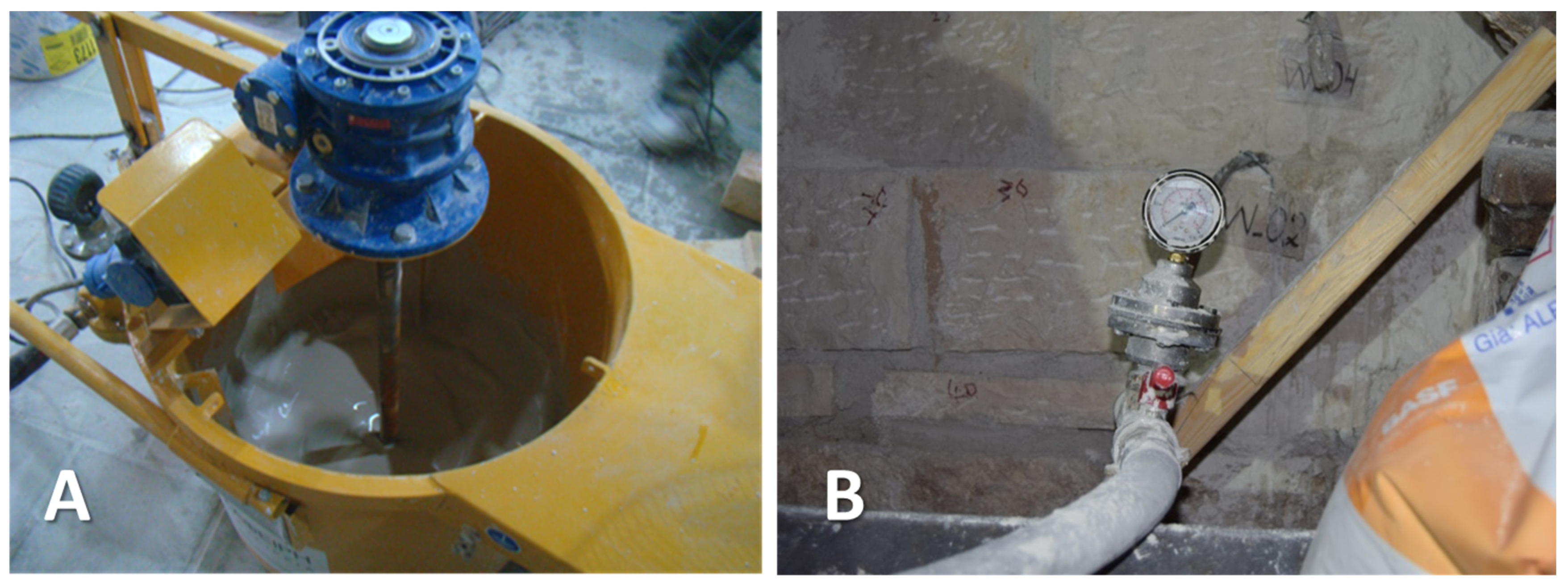
2.1. Grouting Material

A commercial lime–metakaolin grout, procured from BASF, was used in the restoration of the Holy Aedicule. The commercial grout was selected taking into account: (i) the compatibility demands, (ii) the performance requirements and (iii) the technical issues arising from the project timeline and construction site limitations.
Specifically, regarding compatibility issues, the characterization of the historical materials (mortars and stones) allowed for the design and selection of the most compatible restoration mortar synthesis. On account of the high diversity of historical mortars in the structure (lime mortars, hydraulic lime mortars, lime–gypsum mortars, gypsum mortars), the wide range of porosity values, as well as the presence of highly soluble salt percentages, in the historic materials in combination with intense rising damp issues [12,13], it was decided to apply a lime–metakaolin-based mortar, without cement, in order to achieve compatibility and resilience in a highly aggressive environment. Aiming to enhance the homogeneity of the restored structure, it was decided to also apply a lime–metakaolin-based restoration grout.
A dynamic structural analysis based on the finite element model of the Holy Aedicule offered performance requirements, which were taken into account in the selection of the restoration lime–metakaolin-based grout (requirement for 10 MPa compressive strength of the grout) to achieve the adequate mechanical reinforcement of the rehabilitated structure and ensure the structural integrity of the rehabilitated structure under static and dynamic loads [12,14,15,16,17].
The tight timeframe of the project (a total of 12 months) in combination with the limitations posed by the unique worksite (the Holy Aedicule is an internal structure within the Church of Resurrection, with a high number of daily visitors and pilgrims), which was open to visitors and pilgrims throughout the project, demanded the use of a commercial material in order to limit working time and ensure reproducibility of the grout material; furthermore, the presence of metakaolin, a highly reactive pozzolan, in both the mortar and grout materials, ensures the fast consumption of the lime’s free calcium hydroxide, while guaranteeing early acquisition of mechanical strength [12,22,23,24].
The commercial grouting material is cement-free lime–pozzolan (metakaolin) grout with a very fine particle size (<12 μm), high flowability and excellent maintenance of workability. Furthermore, it expands in the plastic phase, thereby ensuring that even the smallest voids are filled. It does not release water-soluble salts or induce the formation of efflorescence, while it presents excellent resistance to sulfates. It develops compressive strength >10 MPa and may therefore be classified as an M10 type according to 998/2. The dry grout was added to the appropriate amount of water, according to the manufacturer’s directions, and mixed in the grouting vessel (Figure 1). One kilogram of dry grout material corresponded to 1.35 L of liquid grout.

2.2. Grouting Procedure

After the removal of the exterior stone facings enclosing the monument, it was observed that the internal masonry was in a bad state of preservation. It was decided to conduct grouting to strengthen the structure, as well as to homogenize the construction phases and structural layers of the Holy Aedicule. The masonry was accessible only from the exterior panel areas where the facings were removed (Figure 2: coding of panels; Figure 3: example of accessible masonry at each panel, herein called panel masonry).
Before the injection of grouts, the masonry was cleaned of loose mortars and the selected restoration mortar was applied at the masonry joints [12]. In some areas of the structure, as the lower part of the masonry was in a bad state of preservation and posed a threat to structural integrity, new orthogonal stones, of the same lithotype as the original ones, were placed and joined by the restoration mortar [12,13,14,15]. This was the case in the areas around the Tomb Chamber, and specifically the lower parts of panels N3, N4, N5, W, S5, S4 and S3 (see Figure 2).
A grid was designed and masonry injection tubes (10 mm diameter) were inserted at 1/3, 1/2 and 2/3 of the masonry thickness, aiming to inject grout into various depths of the masonry. This was important, taking into account that grout injection was mostly possible from the exterior of the masonry, as the internal marble cladding of the masonry was not removed during the project, except for in specific areas. Each tube was coded and its exact position on the masonry was recorded to facilitate detailed grouting documentation.
Prior to the grouting procedure, a number of safety measures were taken to protect important architectural and historical elements from possible grout escape. To this end, the Holy Aedicule was closed to pilgrims for 48 h and the marble cladding enclosing the carved rock surface of the original Tomb was lifted, in order to protect the rock surface from possible grout escape. Thus, the grouting of the Holy Aedicule structure, presented herein, was conducted in a limited timeframe of 48 h [17].
The injection of the grouting material was conducted, moving from one panel to the next, in a counterclockwise rotation, beginning at panel EN and ending at panel ES (Figure 1). Grouting was implemented in two phases: (i) the masonry zone up to 1.5 m was grouted during the first phase; (ii) the masonry zone from 1.5 m up to 3 m was grouted during the second phase (Figure 3), always taking care to not exceed 1 bar pressure. Thus, grout was injected under low pressure through each entry point, gradually filling all the internal cracks/voids interconnected with this entry point. Whenever grout overflow was observed from another grouting tube or an exit point, the grouting tube was sealed (and thus nulled from the process) or the exit point was sealed in order to stop grout overflow from the internal structure. Grouting was continued from the aforementioned entry tube, until all cracks or voids interconnected with the specific entry tube were filled with grout and the low pressure applied could no longer support the injection of grout material inside the masonry. The specific grout entry tube was then sealed off, the total volume of grout consumed through this entry tube was recorded and grout began to be injected in the following tube, until all tubes had been nulled, either as entry or exit points.

2.3. Applied Techniques

On the first level of analysis, the detailed grouting data were recorded and analyzed through the use of Microsoft Excel Spreadsheet Software. This facilitated the management and presentation of the detailed grouting data results, including analysis of grouting data per panel area and zone, analysis of grouting data per grout injection tube in accordance to the timeline of grouting, as well as the grouting tube interconnectivity.
A second level of analysis utilized the spatial coordinates of each grouting entry and exit point, which were provided by a 3D model of the structure. Specifically, a 3D model of the Holy Aedicule [25,26] was created utilizing the most contemporary geomatics techniques and specialized instrumentation, including an automated 3D imaging methodology based on high-resolution digital images, terrestrial laser scanning and high-accuracy geodetic measurements. As a result, all geospatial data were accurate and georeferenced to an existing local plane projection reference system [27] from previous work of the NTUA. After the removal of the panel facings, nd the cleaning and repointing of the masonry, the implementation of the strengthening measures (e.g., construction of the restoration masonry) and the installation of the grout tubes, the NTUA 3D model was then updated with additional laser scanning and photogrammetric data to provide a 3D textured model of the revealed panel masonry areas. In addition, after the top amber hued marble plate was shifted out of position from the Tomb to reveal the rock burial surface [17], this surface was also documented and integrated into the 3D model that represented the Holy Aedicule during the grouting stage. This updated model was used for the correlation of geospatial data with the detailed grouting data in the present work.
A third level of analysis merged grouting data, geospatial data and ground-penetrating radar (GPR) prospections to reveal the internal structure and assess the state of preservation. This was conducted in a pilot manner for the tube that presented the highest grout consumption and interconnectivity.
GPR is an established geophysical technique for non-destructive testing (NDT) that is increasingly utilized to examine historic buildings and structures to reveal their internal layering and assess their state of preservation [21,28,29,30,31,32]. It is based on the propagation, diffusion, absorption and reflection of electromagnetic pulses through structural materials or soils, and on their signal analysis, in order to create a 2D or 3D “image” of the subsurface volume of the examined building, structure or area. The propagation, diffusion, absorption and reflection of GPR pulses are dependent on the dielectric constants of the probed materials. The larger the difference in the dielectric constants between two materials, the “easier” it is for GPR to identify their interface. In the case of cultural heritage assets, GPR provides complementary information that cannot be readily derived by other NDTs, either due to their surface character (e.g., infra-red thermography) or their limited depth of penetration (e.g., pulse-echo ultrasonics).

3. Results and Discussion

3.1. Analysis of Detailed Grouting Data

In certain areas, no significant amount of grout could be injected into the tubes. This occurred for a total of 221 tubes, whereby a total of only 66.3 L was injected. The minimal amount of grout injected through these tubes implies that the masonry around them or behind them was in a good state of preservation.
However, in other areas, higher volumes of grout were injected. A total of 74 tubes allowed for considerable grout injection, amounting to ~944 L; in some cases, grout flowed within the masonry and escaped from various exit points (either injection tubes not yet used in the timeline of grout injection, or other areas), while in other cases, no grout escape was noticed, thus not providing information regarding the path of grout flow within the masonry. Specifically, 51 injection (grout entry) tubes revealed interconnections with other areas of the masonry and grout exited from a total of 167 points, while only 23 injection (grout entry) tubes did not present interconnections with any grout exit point. During this process, a total of 79 grout tubes were nulled from the grout injection process, as they functioned as grout escape tubes during the grouting process. The high interconnectivity of certain grout injection tubes with other areas of the masonry reveals interconnecting voids/cracks/interfaces in the internal part of the masonry.

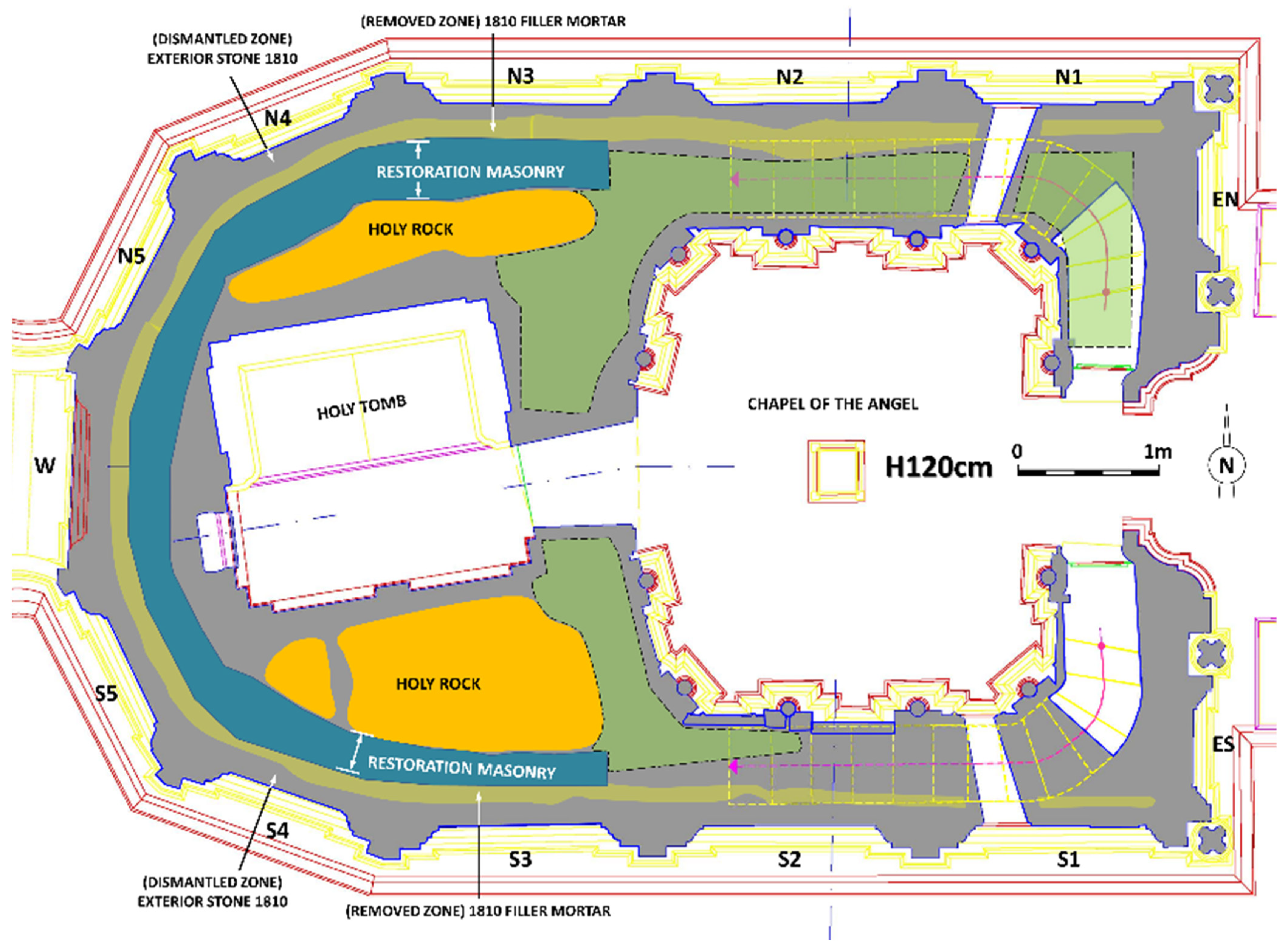
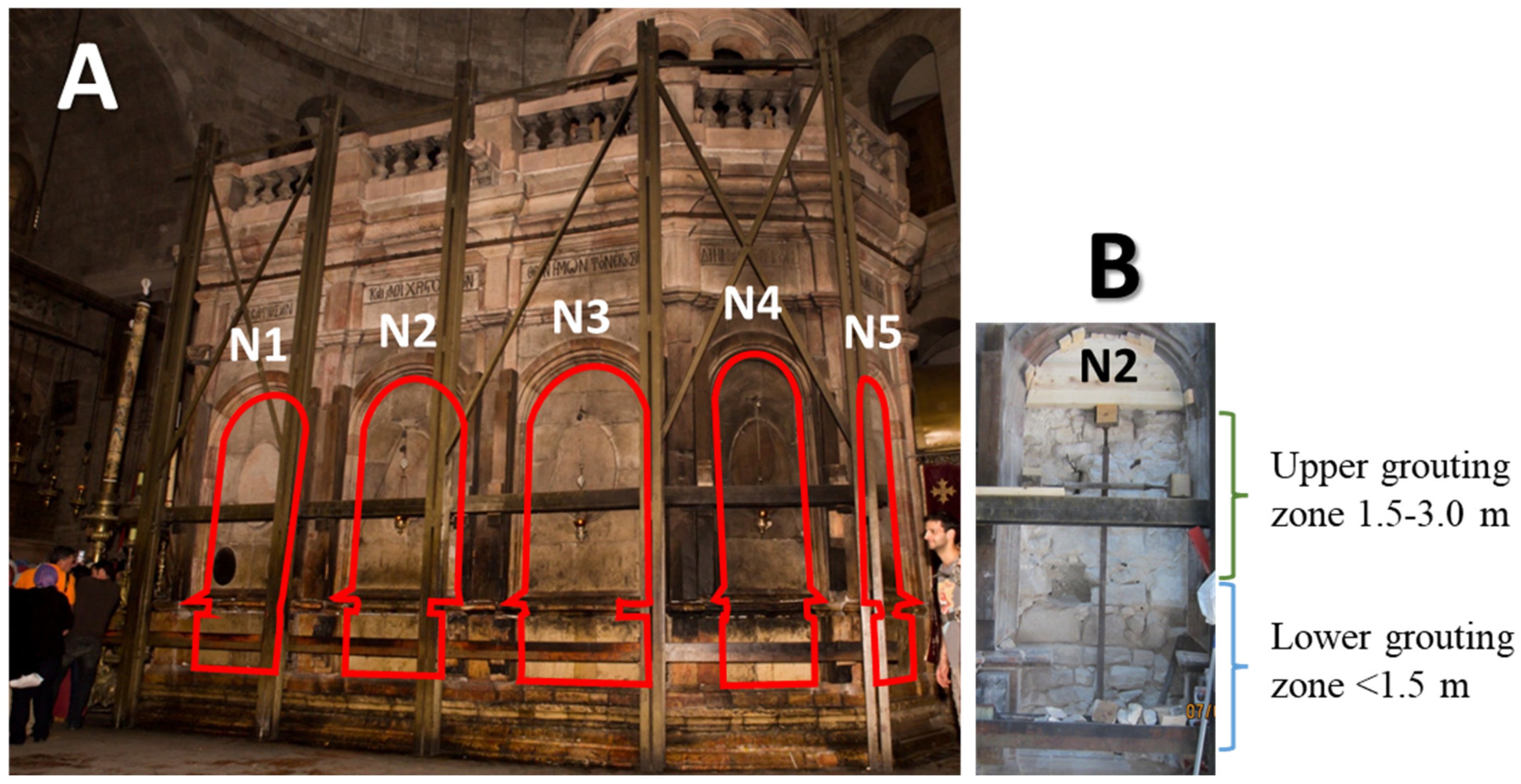
3.1.1. Analysis of Grouting Data per Panel Area and Zone

At the first level of grout injection assessment, the total amount of grout injected at each panel was calculated (Figure 4). It is obvious that the panels of the east side of the Holy Aedicule (EN, ES) did not require any significant grout injection quantities. This is, however, not completely unexpected. As is evident in Figure 2, the masonries around the Chapel of the Angel (eastern part of the Holy Aedicule) present a smaller thickness compared to the masonries around the western part of the structure. Behind the eastern façade, in particular, two internal stairways are present, leading to the top of the Holy Aedicule; the presence of these stairways further diminishes the thickness of the masonries behind panels EN and ES. Moreover, according to an analysis of the structural evolution of the Holy Aedicule [19], the eastern façade’s masonry most probably belongs to the later construction phase (1810), and is thus expected to be in a much better state of preservation than the western parts of the Holy Aedicule.
It is worth noting that in both the lower and upper grouting zones, the highest amount of grout was injected in panel N3. This panel is of particular interest, since according to the architectural–geophysical analyses [19,21], it corresponds to the interface between the burial chamber (with remnants of the original Holy Aedicule embedded within) and the pre-Chamber (Chapel of the Angel), constructed at a later phase [18,20]. Furthermore, the masonry behind panel N3 contains (i) parts that were reconstructed in the 2016–2017 rehabilitation works, (ii) parts of the 1810 Komnenos restoration, (iii) remnants of the original monolithic Aedicule (Holy Rock—see [21]), and (iv) parts of the masonries constructed by the Byzantines/Crusaders to form the Chapel of the Angel [18]. This amalgamation of different construction phases and various materials, and the rather complex 3D geometry in which they are intertwined, can arguably justify the increased grout consumption in this area.
Regarding the lower zone of grouting, grout could not be injected in panels N4 and N5. However, it should be taken into account that (i) the masonry in these areas was extensively reconstructed, and (ii) grout had already flowed to certain injection tubes of these panels, during the injection of grout in the previous panels (see further discussion below—Table 1). In contrast, in the upper zone of grouting, where the effect of the reconstructed masonry is minimal, the injected volumes of grout in panels N4 and N5 were largely comparable to those of the other panels.
The total volumes (lower and upper zones) of grout injected for panels EN to N5, panel W, panels S5 to ES and at interior grouting locations are 468.72 L, 31.38 L, 469.53 L and 40.65 L, respectively. The corresponding volumes regarding the lower grouting zone alone are 286.06 L, 31.38 L, 279.85 L and 18.89 L, respectively. These values indicate that the north and south parts of the Holy Aedicule present equal total concentrations of voids/cracks (at least those interconnected and accessible for grout injection). The lower grouting zone consumed approximately 60% of the total grout volume, indicating the higher presence of voids/cracks/interfaces in the lower part of the structure.
Comparing the eastern part of the structure (Chapel of the Angel) with the western part of the Holy Aedicule (Tomb Chamber, embedding the original phase of the Aedicule [18,19]), a differentiation in the grouting behavior is also indicated. The eastern part of the structure is represented by sub-area panels EN to N2 and sub-area panels S2 to ES. The western part of the structure is represented by three sub-areas: panels N3 to N5, panel W and panels S5 to S3, which surround the burial chamber. These five sub-areas indicate some degree of “asymmetry” along the longitudinal axis of the Holy Aedicule, as well as between its western and eastern parts.
Specifically, the total injected grout volumes for panels EN to N2 and S2 to ES are 186.27 L and 123.67, respectively. This indicates that the north part of the Chapel of the Angel required approximately 50% more grout as compared to the corresponding south part. This could be partially attributed to the fact that the grouting of the structure initiated from panel EN and proceeded counterclockwise until it was concluded at panel ES, thus the initial areas could have consumed higher amounts of grout material. However, as indicated in Table 1(see discussion below), the south part of the Chapel of the Angel presents lower interconnectivity between panels as compared to the corresponding north part. The differentiation between the north and south parts of the Chapel should instead be correlated with the different embedded construction phases [21] within the corresponding parts and their state of preservation. Similarly, the south part of the burial chamber (corresponding to panels S5 to S3) required 345.86 L, i.e., approximately 20% more grout material as compared to the corresponding north part of the burial chamber (corresponding to panels N3 to N5), which required 282.46 L. This differentiation is smaller compared to the Chapel of the Angel, and can be attributed to the increased interconnectivity of the various sub-areas around the burial chamber.
The west part of the Aedicule consumed approximately 70% of the total volume of grout for the Holy Aedicule during the first and second grouting phases. This may be attributed to the worse state of preservation of the west parts of the Holy Aedicule (with the exception of the reconstructed parts), to the various interfaces between the structural layers (original masonry, reconstructed masonry, Holy Rock), as well as to the relatively large total volume of the structural elements.

3.1.2. Analysis of Grouting Data per Grout Injection Tube

The interconnectivity of the internal volumes behind the panels is difficult to assess only by analyzing the total volumes of injected grout per panel (Figure 4). Thus, the timeline of grout injection was taken into account. In Figure 5, the cumulative volume of grout injected in the masonry, as the grouting proceeded, is presented regarding the lower and the upper zones of the structure, respectively, along with the relative amount of volume (%) injected in each injection tube.
It is obvious that in certain areas, a sharp increase in cumulative volume is noticed, and these are areas of interest, as they seem to present extensive voids, cracking or interfaces. Moreover, the lower zone, in addition to a higher amount of grout volume injected, apparently presents a different type of networking of cracks, voids and interfaces in relation to the upper zone. This is evident from the form of the curve of the cumulative grout volume injected, which is more “gradual” in the case of the upper zone, compared to the more “sigmoidal” form in the case of the lower zone. Note that the curve for the upper zone is constructed from 176 tubes, whereas that of the lower zone corresponds to 123 tubes, indicating the lower interconnectivity and perhaps higher homogeneity of the upper zone in relation to the lower zone. This can be attributed perhaps to the fact that older construction phases are embedded in the lower zone [19].

3.1.3. Analysis of Grouting Tube Interconnectivity

In order to understand and reveal the presence of interconnecting voids and cracks, as well as the interfaces of different construction phases of the monument, further elaboration was conducted in the specific areas where considerable grout injection was noticed. In Table 1, the number of respective grout entry tubes per panel is correlated to the number of grout exit tubes per panel, for the lower and upper zones, respectively. Other grout escape points, except for grout tubes, were not taken into account at this stage of the assessment. When grout is injected into a panel of masonry and exits from another tube of the same panel of masonry, it is an indication of limited cracks/voids in the area. However, when grout is injected into a panel of masonry and exits from one or more different panel areas, this is a sign of larger interconnecting cracks and voids and, in some cases, could indicate the presence of the interface of different construction phases.
Comparing the data presented in the two parts of Table 1, one can immediately notice the lower extent of interconnectivity between masonry panel areas in the case of the upper zone. This is not expected on the one hand, as the lower part of the masonry, around the Tomb Chamber, corresponds to the restoration masonry. However, on the other hand, it is expected on account of the higher complexity of the structure, in terms of structural layers in the lower zone, as well as the higher possibility of the coexistence of non-homogenized construction phases.
In order to further evaluate the detailed grouting data results, it was decided to investigate the areas that seemed to present a high grout consumption, as well as high interconnectivity with other masonry panels, through the correlation of detailed grouting data with geospatial and geophysical data. For this purpose, masonry panel N3 was selected as a demonstration panel, with special emphasis on grout entry tube N3_01, which presented the highest relative grout volume injected (%) in the lower zone.

3.2. Correlation of Geospatial and Grouting Data

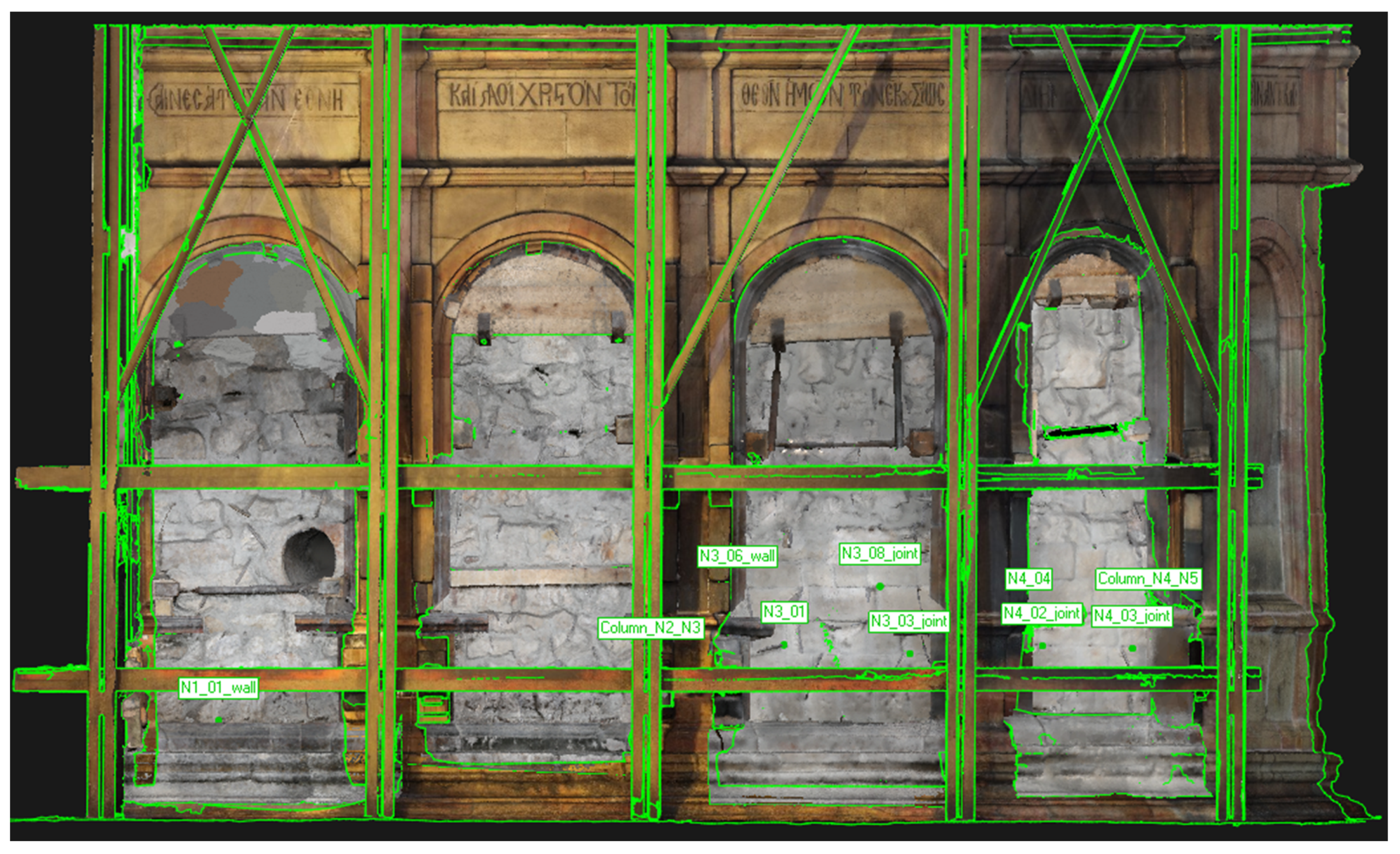
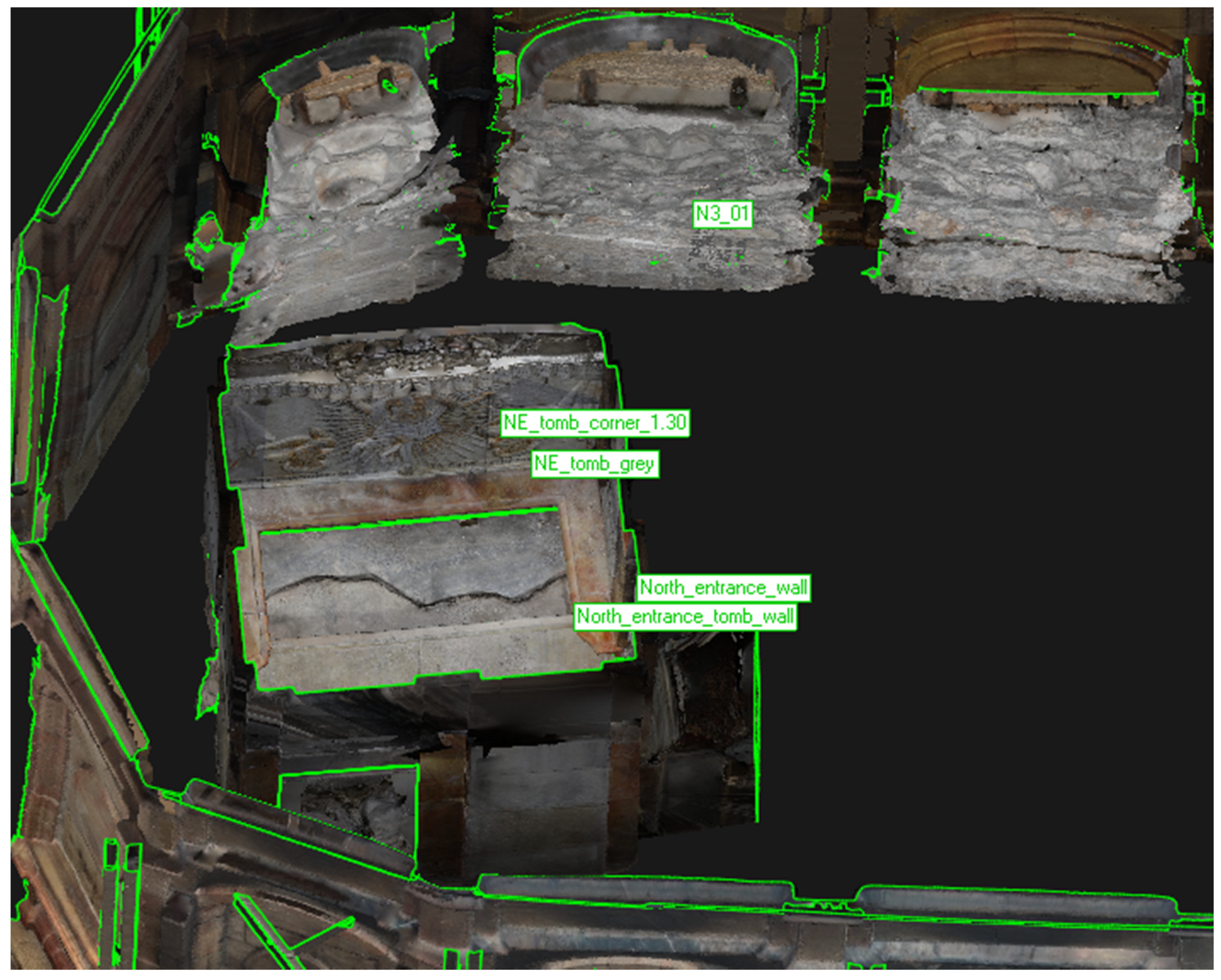
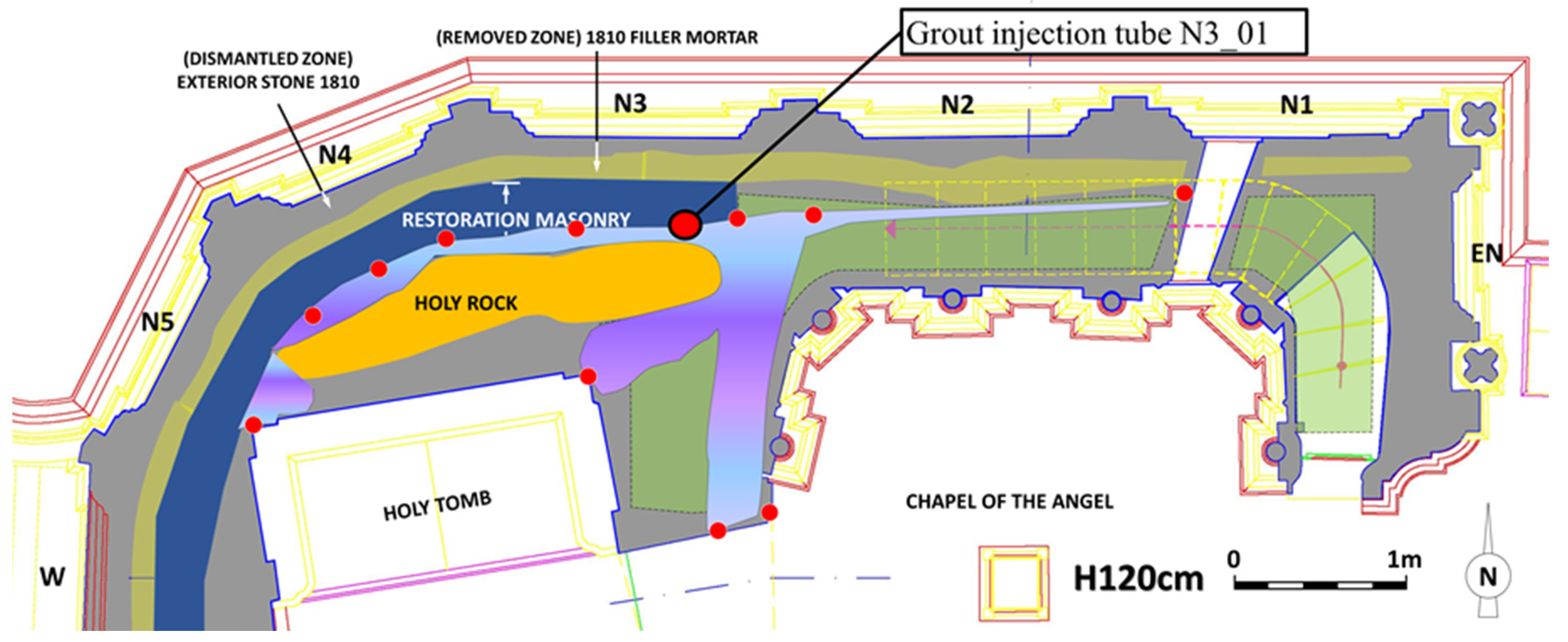
3.2.1. Three-Dimensional Documentation of Grouting Data—Pilot Application for Panel N3

Grouting is a process that takes place in a three-dimensional volume (the structure volume); however, it is physically viewed (and is usually documented and assessed) via a two-dimensional approach, corresponding to the facades where grout is injected and where grout flow is noticed. This two-dimensional approach can reveal areas of the structure with a high presence of voids/cracks/interfaces and/or high interconnection with other areas; however, it provides limited information regarding the internal structure.
Geospatial data and 3D documentation of both the structure and the grout entry and exit points can assist in overcoming this limitation. In the present study, the grout entry and grout exit points were assigned to their exact positions on a three-dimensional model of the Holy Aedicule. Thus, the x,y,z coordinates of each point are fully documented and described, and the interconnectivity of the different areas of the structure can be visually observed, towards a 3D approach, which can reveal the internal structural features and possible grout flow routes within the structure.
In order to illustrate the proposed process, in the present work, the grout entry tube assigned N3_01 (which presented the highest relative grout volume consumption) was selected. In Figure 6, the aforementioned tube is represented along with its corresponding grout exit points (those that are related to the exterior masonry). This representation shows a high interconnectivity of panels N3 and N4 at this height of the structure. In Figure 7, tube entry N3_01 is represented along with its corresponding exit points, related to the interior of the structure. This representation implies the presence of interfaces within the structure that allow the flow of grout to the interior of the structure.
However, the graphical representation alone does not allow for adequate knowledge of the extent and configuration of the cracks/voids/interfaces. For this purpose, the geospatial information (x,y,z coordinates) deriving from the 3D modeling (Figure 7 and Figure 8) is utilized for the correlation of entry and exit points. This issue is discussed and analyzed in the next section in detail.

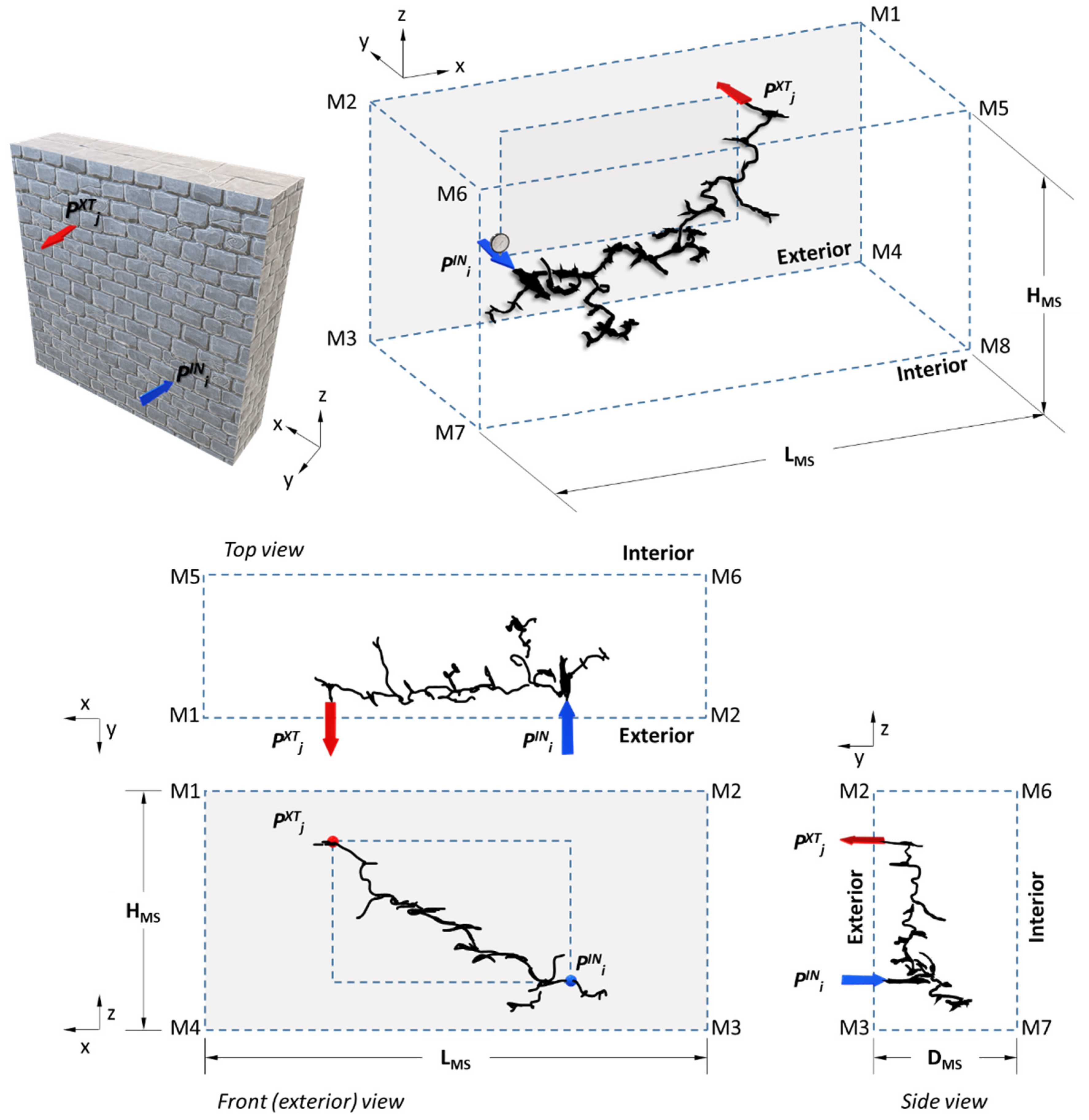
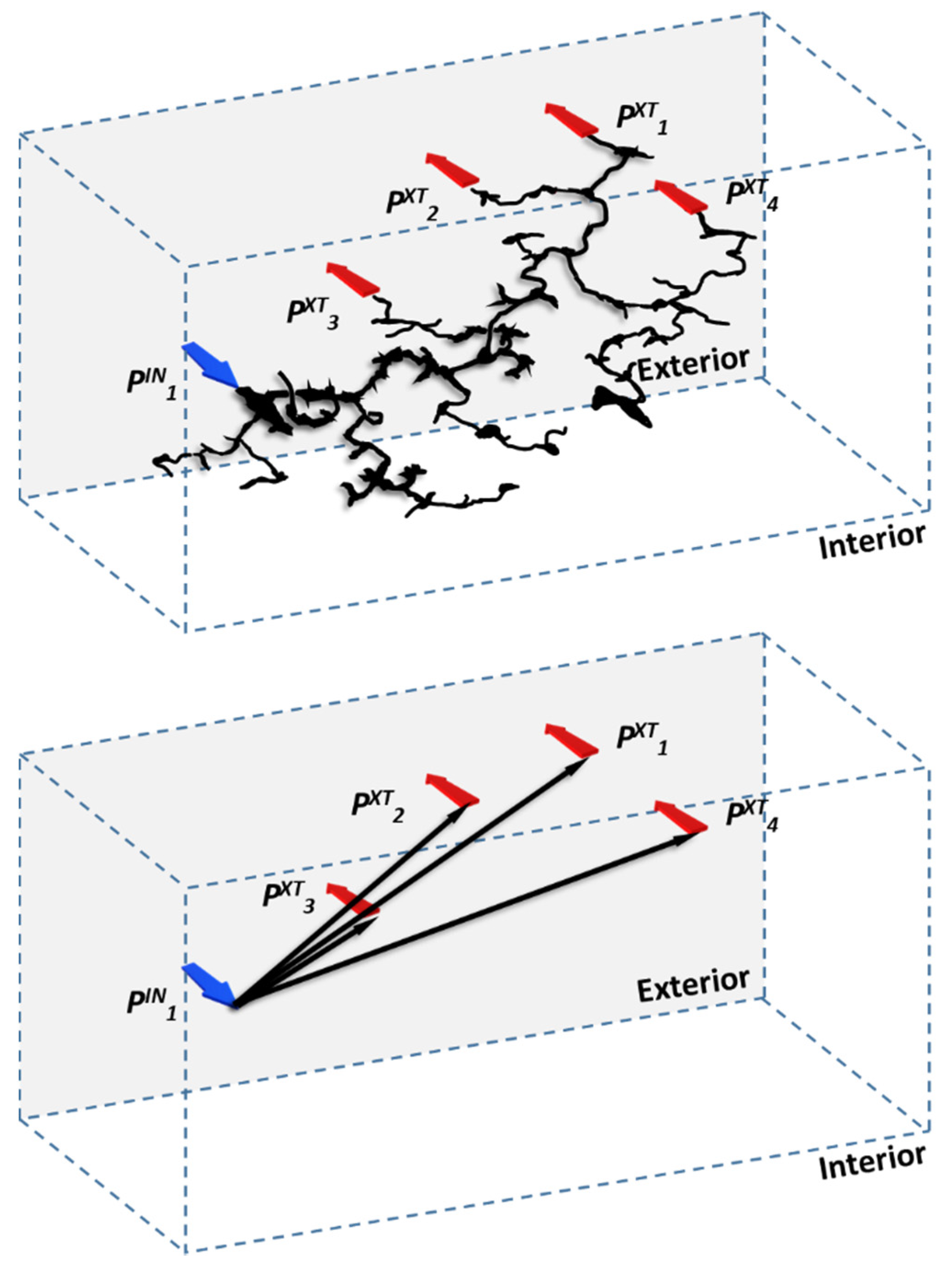
3.2.2. Development and Application of Grouting Indices—Pilot Application for Panel N3

Usually, when documenting a grouting process, the total volumes of consumed grout material per entry point are illustrated on architectural plans to provide a pseudo-quantitative or a qualitative measure of the perceived effectiveness of the grout insertion [4], without effectively linking them to the related exit points. Thus, areas of masonries or structures that require relatively increased grout volumes are considered to correspond to areas with an increased presence of internal cracks or voids. Although this is a logical approach, which provides valuable information on the first level of assessment, it is not adequate; such a value-based approach “assigns” the grout consumption to the entry point and effectively discards all the hidden three-dimensional information that this consumed grout volume contains. In order to address the above issues, specific grouting indices are developed in this work, which are applied and evaluated in characteristic areas of the use-case of the Holy Aedicule of the Holy Sepulchre.
Before the indices are described, it is important to understand the 3D characteristics of the void space within the examined masonry that is supposed to be filled with grout. As described above, only the actual positions of the entry and exit points can be described. It is understandable that the interconnecting cracks, voids and channels that the grout material followed prior to its exit on the masonry surface do not form a single non-branched “channel”. Instead, the actual path can be compared to a “cluster of interconnecting branches” or a “cluster of interconnecting paths”. From this 3D cluster of branches, at least two points are known: the entry and exit point(s).
The volume of masonry (VMS) is mainly composed of the building materials of the masonry (e.g., stones and mortars). However, internal cracks and voids are present within the masonry. The cumulative volumes of the cracks/voids within the masonry (VVOIDMS) are not necessarily interconnected. Much like the porosity of a material, only a certain volume of cracks/voids (VOPENMS) is accessible from the exterior surface. Practically, the volume of open channels VOPENMS may not actually be completely accessible from the exterior surface, for a variety of reasons; therefore, technically, the grouted volume (VGROUTMS) could be lower than the total volume of cracks/voids (this, however, is to a certain extent eliminated by the design of an appropriate grout injection grid). Obviously, the following applies: VGROUTMS ≤ VOPENMS ≤ VVOIDMS << VMS.
Figure 8 is a schematic representation of a typical grouting process from an entry point PINi to an exit point PXTj. A masonry section is depicted, which has a volume VMS = LMS·HMS·DMS, whereas the area of its exterior surface is AMS = LMS·HMS. In order to illustrate the complexity of grout flow, even in the simplest of cases, both entry and exit points are assigned on the exterior surface of the masonry. Due to the low pressure applied during the grouting of historical structures, the accessible parts of the cluster of interconnecting voids will gradually be filled with the fluid grout material (black-colored “path”). The grout will continue to flow, filling the interconnected channels/voids/cracks, until:
  • One branch of the grout-filled cluster of interconnecting paths finds an exit point on the exterior surface (PXTj)—this exit point is sealed, the grouting process is halted, the entry tube is sealed off and the consumed grout volume VGROUTij is recorded;
  • The interconnected cluster of paths is completely filled and no more grout can be injected under the pressure applied, but no exit point is observed on the surface. In this case, the grouting process is halted, the entry point is sealed off and the consumed grout volume VGROUTij is recorded.
As apparent in Figure 8, the depicted path filled with grout material corresponds to the cluster of interconnecting branches at the moment t11 when grout material overflows from the first exit point PXT1. Effectively, the depicted volume of grout material corresponds to the volume injected in the masonry between to (initiation of injection) and t11. If, theoretically, the exit point was immediately sealed off and the pressure was zeroed instantly, no further penetration of grout and filling of open voids would be feasible. The depicted cluster of interconnecting paths can thus be considered as a “snapshot” of the grouting process at time t = t11. The corresponding volume would then be denoted VGROUT11, i.e., the recorded volume of the grout-filled paths between entry point PIN1 and exit point PXT1.
In a case in which, after sealing off the first exit point at time t = t11, low-pressure grouting continues (on account of the grout following other interconnecting crack(s)/void(s)), the gradual filling of the open spaces of the cluster of voids/channels will continue until time t = t12, whereat grout material overflows from an exit point PXT2. Similarly, if low-pressure grouting continues, between time t12 and t13, grout will overflow from an exit point PXT3. The same applies for all subsequent exit points.
Although the exact path of grout flow cannot be accurately determined, geospatial data, derived from the 3D model, can provide the locations of the entry and exit points (x,y,z). This allows for the calculation of the vector length (distance) λij between an entry point PINi and each exit point PXTj. The following grouting index IVVLi can thus be defined:
I i V V L = V i G R O U T j = m n λ i j = V i G R O U T T V L i  
where V i G R O U T = j = m n Δ V ( t i j ) , ΔV(tij) is the differential volume of grout material consumed between time tij−1 and tij, when grout overflowed from exit point PXTj and the Total Vector Length T V L i = j = m n λ i j .
If the differential grout volumes per exit point are available, V i G R O U T is the sum of these differential volumes. However, in practical application, as in the case study of this work, V i G R O U T is the only value recorded per entry tube, at the end of grouting from this position, and is the value directly used for the calculation of this grouting index.
This grouting index provides a spatial correlation between the grout injected from entry point PINi and the spatial distribution of the exit points PXTj. This spatial correlation is first attempted through the use of the total length of the individual vectors between the entry point and the exit points PXTj. This is depicted in Figure 9, where the individual vectors between the entry point and the exit points replace the three-dimensional grout-filled cluster of interconnecting voids, which is of course a simplified, but still valuable, preliminary approach.
Apart from the spatial distribution of the grout path between entry and exit points, it is also important to assess the degree of crack/void/interface branching and estimate the type of cluster configuration. Indices I i V N X and I i V L N aim to provide a measure of the aforementioned issues:
I i V N X = V i G R O U T N i X T
where N i X T is the number of exit points for entry point PINi.
I i V L N = T V L i N i X T
where Total Vector Length T V L i = j = m n λ i j .
It should be stressed that all indices should be evaluated in conjunction with the total grout volume injected per tube, as well as the total vector length, as well as the interconnectivity data examined (Table 1).
In this work, the three above grouting indices are calculated for the use-case of the rehabilitation of the Holy Aedicule, and more specifically, for a pilot study, in the case of masonry N3, which, according to the detailed grouting analysis, is a particularly interesting area of high complexity. Specifically, they are applied for the case of tube entry N3_01, which presented the highest grout volume consumption and, at the same time, the highest interconnectivity. For comparison of the grouting indices for masonry N3, the same indices were also calculated for other tubes that exhibited high grout consumption in facades N1 and N2, i.e., the façades that preceded N3 in the grouting process. Table 2 and Figure 10 summarize the results.
This comparison demonstrates that additional information is available when calculating the above-described grouting indices. Assessing only the grout volume consumed per entry tube would only indicate that increased amounts of grout V i G R O U T were needed for entry tube N3_01 (i.e., façade N3), compared to N2_20 (façade N2) and N1_07 (façade N1).
However, such a consideration does not take into account the different structural layers of the masonry sections corresponding to each panel, or their different thicknesses. Specifically, as shown in Figure 2, panels N1 and N2 correspond to the north part of the Chapel of the Angel. Panel N3 corresponds to the western part (burial chamber) of the Holy Aedicule, which embeds the original Constantinean Aedicule structure [19,21] and remnants of the original monolithic Aedicule (Holy Rock). Panel N1 is located north of the internal staircase leading to the roof of the Aedicule (Figure 2), and as a result the thickness of the masonry in this area, above the lower zone of panel N1, is greatly reduced. Panel N1 contains a circular opening through which the Holy Light is transmitted during Easter. This opening is located right beneath this internal staircase.
In entry tube N1_07, three of the exit points were located in the masonry area of N1 and two in the masonry area of N2. In contrast, in the case of entry tube N2_20, two of the exit points were located in the masonry area of N3 and two in the masonry area of N4. In comparison, in the case of entry point N3_01, grout overflowed in the interior of the burial chamber, at the low entrance to the burial chamber, and as far as panels N4 and N1 (Figure 6). Although the grout volume consumed at N3_01 was approximately twice the volume consumed at tube N1_07, the grout injected in tube N3_01 exited from a much larger number of exit points and covered longer distances (total vector length, Table 2). These differences reflect the different natures and potentially the different cluster patterns of the two cases.
The grouting indices provide additional information. As the calculations show, index I i V V L for N3_01 is approximately three times lower than that for N1_07. Similarly, index I i V N X is only 25% lower. In addition, if the grouting index I i V L N is also taken into account, a better understanding of the nature of the clusters of interconnecting voids is provided. Specifically, N1_07 and N3_01 demonstrate index I i V L N values of 0.83 and 1.82 m, respectively, i.e., the index value for N3_01is approximately twice that of N1_07.
It is thus theorized that the cluster of interconnecting voids and channels for the case of N3_01 probably corresponds to a configuration of longer small-diameter paths, compared to a configuration of shorter-length and larger-diameter paths in the case of the entry tube from N1. This is justifiable by the different construction phases of the corresponding masonry sections, their different states of preservation, as well as their different configurations, and thus their potential for more internal interfaces.
In comparison, the case of N2_20 appears to demonstrate an intermediate behavior, closer to that of the N3 tube case. The V i G R O U T is approximately 25% higher than the value for N1_07; however, all exit points were either at N3 or N4, the exit points at N4 being almost 2.9 m away from the entry point. Compared to the values for N1_07, the value of N2_20 for index I i V V L is approximately 25% lower, while index I i V N X is approximately 50% higher, TVLi is approximately 70% higher and index I i V L N is approximately double. Index I i V L N is almost identical to the one of N3_01. If these indices are correlated with the structural layers and the relative positions of the corresponding panels, it can be theorized that the clusters of interconnecting voids for the case of N2_20 were similar to those of N3_01.
Although the differences in these indices better highlight the different internal structures behind the panels, in comparison to the detailed grouting analysis, potential grout paths can only be assessed through correlation with additional prospection data. Such information is provided by the non-destructive technique of ground-penetrating radar, as described below.

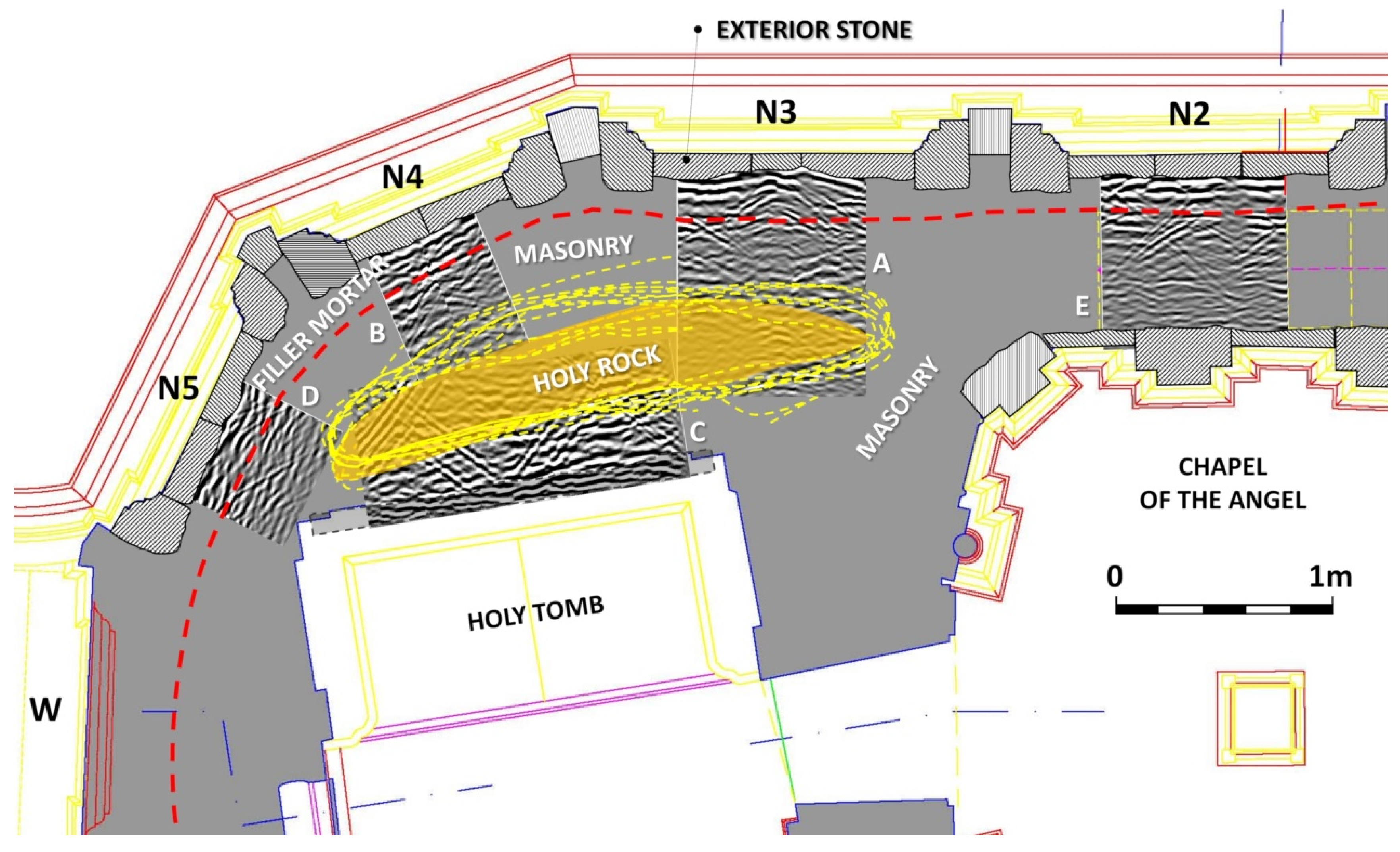
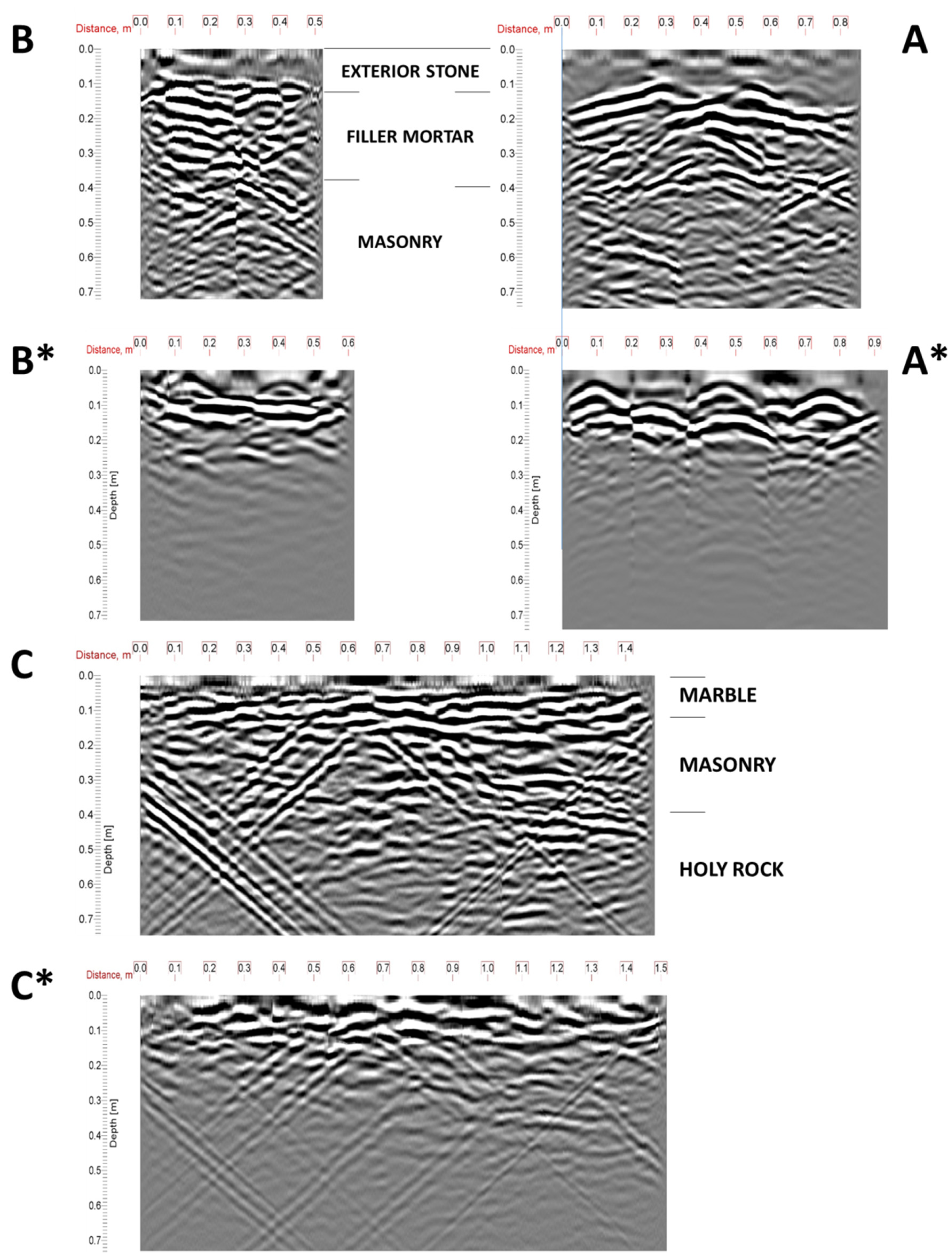
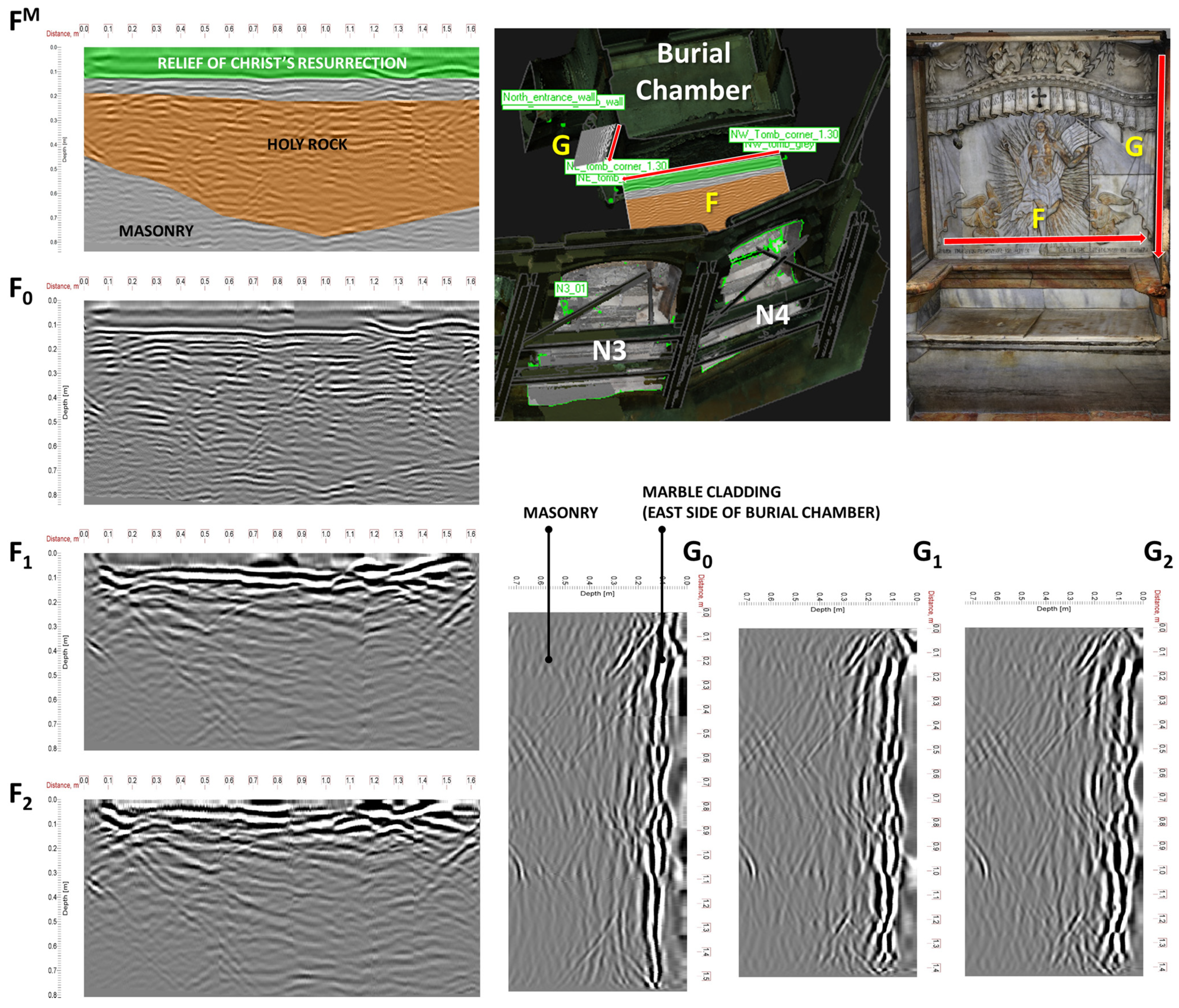
3.3. Merging Grouting Data, Geospatial Data and GPR Prospections to Reveal the Internal Structure and Assess the State of Preservation—Pilot Application for Panel N3

Prior to the initiation of the grouting process, GPR was utilized through its typical methodology [29], to reveal and identify, if possible, internal cracks, voids and interfaces. These features produce characteristic reflection patterns, which aid in the revealing and mapping of the internal layering of masonries and structures. During the grouting process, GPR can be employed to potentially “record” the “intrusion” of the grout material into the aforementioned cracks, voids and interfaces. However, uneven and obstructed (grout tubes) examination surfaces and the rather high humidity content of the masonries (to enhance grouting effectiveness) hinder the use of GPR. In the case of the Holy Aedicule, GPR prospection was only feasible on selected marble surfaces of the interior of the burial chamber. After the completion of the masonry strengthening measures and the reassembling of the stone façades, the same areas were re-scanned with GPR, in order to provide a comparative “image” of the strengthened structure.
Figure 11 depicts the overlay of processed GPR scans over the exterior and interior surfaces of the Holy Aedicule, prior to the initiation of the restoration project. These scans correspond to the same height level as entry tube N3_01. The per-height outlines of the north block of the Holy Rock are also depicted, as identified by the relevant analysis [29], as well as the internal layering.
Figure 12 illustrates a typical example of a comparative evaluation of GPR scans in the pre-grouted and post-grouted structure. The GPR radargrams A, B and C are the ones also depicted in Figure 11, and represent the layering and state of preservation of the historic masonry prior to the grouting process. These scans are at the same height level as the entry tube N3_01. GPR radargrams A*, B* and C* are the corresponding radargrams at the same positions as A, B and C, after the completion of the rehabilitation works. It should be noted that scans A* and B* represent different types of layering compared to the layers of A and B, but are of the same thickness. Specifically, the historic (damaged) masonry in scans A and B is replaced with restoration masonry in A* and B*. The filler layer in A* and B* consists of the restoration filler mortar and titanium mesh, as compared to the disintegrated historic filler mortar. The exterior stone panels in A* and B* have titanium connectors installed. Scans C and C* correspond to the area below the relief icon of Christ’s resurrection, in the burial chamber.
In the cases of scans A* and B*, it is apparent that the reflection patterns present in scans A and B are greatly reduced. This is partly attributed to the presence of the restoration masonry, but it can also be partially attributed to the successful grouting of the remaining internal voids, especially in the vicinity of the restoration masonry/Holy Rock interface. As aforementioned, grout tube N3_01 consumed increased amounts of grout material. The comparison of the GPR scans around this tube (i.e., facades N3 and N4), before and after the restoration works, indicates that this increased amount successfully filled all the remaining voids, significantly homogenizing the structure in this area.
The comparison of scans C and C* can provide some indications about the potential grouting paths around the northeast part of the Holy Rock. Specifically, as shown in Figure 13, the insertion of grout from tube N3_01 overflowed from various grout exit points. One of them, in particular, is located at the northeast corner of the burial chamber, at the corner junction between the marble relief of the Anastasis and the east marble panel. However, the comparison of scans C and C* does not indicate any significant variations, other than a relatively small decrease in the reflection pattern in the east side of the scans (end of scan); this area corresponds to the area around the grout exit point in the northeast corner. This indicates that no grout entered the zone between the interior marble relief facings and the adjacent side of the north Holy Rock block. Note that the masonry separating the Chapel of the Angel and the Burial Chamber is perhaps the result of two construction phases, and additionally may create an additional interface with the Holy Rock, thus offering a potential grout flow path.
In order to verify this assumption, a matrix of systematic vertical and horizontal scans was constructed over marble surfaces at the interior of the burial chamber, at specific time intervals during the actual grouting process. Specifically, Figure 14 shows typical scans over the marble relief of Christ’s resurrection and the east side panel of the burial chamber. GPR scan F0 was the one scan that was conducted at the same height level as the grout exit point at its end. Scan F0 was conducted prior to the initiation of the grouting process. Scan FM depicts the velocity model applied to the scan F0, which was used for the conversion to depth scale. The green zone corresponds to the marble relief, whereas the orange zone is the Holy Rock. Scans F1 corresponds to GPR prospection at the same location as in scan F0 after the completion of the process at the lower grouting zone (see Figure 3). Scan F2 was the corresponding scan after the completion of the whole grouting process in both grouting zones. Similarly, the GPR scan G0 was the northern scan in the group of scans conducted over the east side panel that was closest to the grout exit point in that corner. Scans G1 and G2 correspond to the stages of scans F1 and F2.
No significant temporal variation in the reflection patterns is observed in both cases (F and G). This indicates that the area between the marble relief and the Holy Rock block received minimal (and perhaps no) grout material. The other horizontal and vertical scans conducted on this area showed a similar behavior.
The above analysis indicates that the exit point in the northeast corner of the burial chamber probably corresponds to a grout path originating from N3_01, flowing around the Holy Rock block. Upon reaching the well-connected zone between the marble relief and the rock block, it cannot flow further, and thus it exits from the first exit point available, i.e., the northeast corner. This is depicted in Figure 13.
Similarly, the grout exit points at the locations northeast of the low entrance (interior) are probably attributed to the paths depicted in Figure 13. These paths are probably related to interfaces created by the various transformations of the area between the burial chamber and the Chapel of the Angel throughout the centuries.
The use-case of grout insertion point N3_01 and the discussion about the relevant exit points demonstrate the benefits of such a holistic analysis. The correlation of grouting data with geospatial information and ground-penetrating radar prospection information offers an improved understanding of the actual grouting paths and justifies the locations of the exit points. In turn, this transforms the grouting process into a tool for “imaging” the structure, in the generic sense of the term. In any case, the joint analysis of grouting data, geospatial information and GPR information enables us to deduce critical 3D information about the grouted structure that would not be available otherwise.

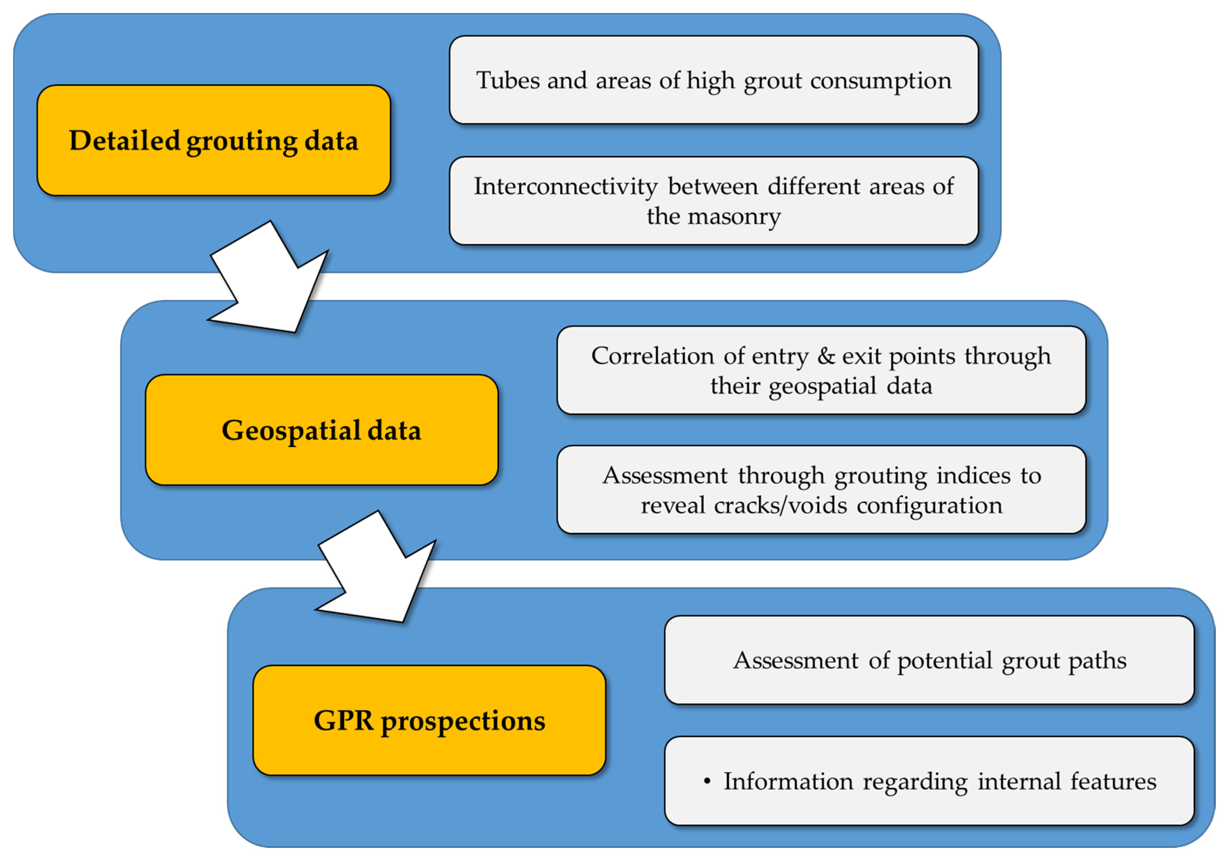
3.4. Methodological Approach

The above analysis allowed for the development of an evolved interdisciplinary methodological approach (Figure 15) regarding the assessment of the state of preservation of the internal structure of a complex monument based on the results of the grouting procedure, in conjunction with geospatial and geophysical data, which can be applied to other complex historical structures. This approach begins with a 2D level of information and, incorporating 3D data, evolves into a 2.5D approach.

4. Conclusions

The high complexity of the internal structure of the Holy Aedicule is the reason for the limitations of the typical 2D documentation approach and the mapping of grout quantities over the various grout injection locations. The analysis of detailed grouting data can provide information regarding areas of interest; however, it cannot reveal specific information regarding the state of preservation and the configuration of internal cracks, voids and interfaces. Thus, this process was evolved, embarking on an area-by-area analysis, taking into account the geospatial data of grout entry and corresponding grout exit points, as well as structural data, as measured by GPR.
The above analysis revealed the different states of preservation of the various parts of the Holy Aedicule, and confirmed the historical analysis regarding its construction phases and evolution. The multiple construction phases and materials accumulated in the western part and lower level of the structure resulted in the increased presence of interfaces, which required the injection of increased quantities of grout.
This research allowed for the development of an interdisciplinary approach, which can provide insight regarding the internal features of a complex historical structure, such as the Holy Aedicule. This approach, beginning with 2D information and evolving into a 2.5D approach, has potential to further evolve into an enhanced 3D approach in the future.

Author Contributions

K.C.L. assisted in the development of the methodological approach, developed the grouting indices, conducted and analyzed the GPR measurements and contributed to the writing of the manuscript; M.A. conducted the documentation of the analytical data of the grouting process and contributed to the writing of the manuscript; E.T. analyzed the geometric data and geospatial information; A.M. was responsible for the scientific administration and scientific supervision of the research team, the scientific conceptualization and visualization of the project, and research. All authors have read and agreed to the published version of the manuscript.

Funding

This research was based on the results of the Holy Aedicule project, completed in 2017. The current research received no external funding.

Institutional Review Board Statement

Not applicable.

Acknowledgments

The study and the rehabilitation project of the Holy Aedicule became possible and were executed under the governance of His Beatitude Patriarch of Jerusalem, Theophilos III. The Common Agreement of the Status Quo Christian Communities provided the statutory framework for the execution of the project; His Paternity the Custos of the Holy Land, Archbishop Pierbattista Pizzaballa (until May 2016—now the Apostolic Administrator of the Latin Patriarchate of Jerusalem), Fr. Francesco Patton (from June 2016), and His Beatitude the Armenian Patriarch of Jerusalem, Nourhan Manougian, authorized His Beatitude the Patriarch of Jerusalem, Theophilos III, and NTUA to perform the project. Contributions from all over the world secured the project’s funding. It is worth noting Mica Ertegun’s and Jack Shear’s donations through WMF, Aegean Airlines et al. The interdisciplinary NTUA team for the Protection of Monuments, Em. Korres, A. Georgopoulos, A. Moropoulou, C. Spyrakos and Ch. Mouzakis, were responsible for the rehabilitation project, and A. Moropoulou, as Chief Scientific Supervisor, was responsible for its scientific supervision with executive role as well. The grouting was implemented by Yioi P. Zafeiri Techniki Ltd and it was monitored by the interdisciplinary NTUA team. This research is utilized in the RESPECT project (An exemplary Information System and Methodology for the integrated management, analysis and dissemination of digital Cultural Heritage data from the rehabilitation of the Holy Aedicule of the Holy Sepulchre).

Conflicts of Interest

The authors declare no conflict of interest.

References

  1. Vogiatzis, S.; Floros, K. Conservation of the Church of the Holy Apostles in Kalamata. In Structural Conservation of Stone Masonry—Conservation Structurelle de la Maçonnerie en Pierre; ICCROM: Rome, Italy, 1990; pp. 485–494. [Google Scholar]
  2. Asthana, K.K.; Lakhani, R. Strategies for the Restoration of Heritage Building with Innovative Active Compatible Materials. In Studies in Art and Archaeological Conservation (Dr. BB Lal Commemoration Volume); Bisht, A.S., Singh, S.P., Eds.; Agam Kala Prakashan: Delhi, India, 2004; pp. 9–26. [Google Scholar]
  3. Keersmaekers, R.; Schueremans, L.; Van Rickstal, F.; Van Gemert, D. Development of an Appropriate Grout for the Consolidation of the Column Foundations in Our Lady’s Basilica at Tongeren (B). In CANMET/ACI International Conference on Recent Advances in Concrete Technology; Malhotra, V.M., Ed.; American Concrete Institute: Farmington Hills, MI, USA, 2006. [Google Scholar]
  4. Miltiadou-Fezans, A.; Kalagri, A.; Kakkinou, S.; Ziagou, A.; Delinikolas, N.M.; Zarogianni, E.; Chorafa, E. Methodology for In Situ Application of Hydraulic Grouts on Historic Masonry Structures. The Case of the Katholikon of Dafni Monastery. In Structural Analysis of Historic Construction: Preserving Safety and Significance; D′Ayala, D., Fodde, E., Eds.; Taylor & Francis Group: London, UK, 2008; pp. 1025–1033. [Google Scholar]
  5. Raptis, K.T.; Zombou-Asimi, A. The Consolidation and Restoration Project of Acheiropoietos Basilica in Thessaloniki. In Proceedings of the 8th International Symposium on the Conservation of Monuments in the Mediterranean Basin-MONUBASIN, Patras, Greece, 31 May–2 June 2010; pp. 411–428. [Google Scholar]
  6. Miltiadou-Fezans, A.; Vintzileou, E.; Mouzakis, C.; Dourakopoulos, J.; Giannopoulos, P.; Delinikolas, N. Structural Analyses of the Katholikon of Daphni Monastery with Alternative Interventions Improving its Overall behaviour. In Proceedings of the 16th European Conference on Earthquake Engineering—ECEE, Thessaloniki, Greece, 18–21 June 2018; pp. 18–21. [Google Scholar]
  7. Miltiadou-Fezans, A.; Delinikolas, N. The Restoration of the Katholikon of Daphni Monastery: A Challenging Project of Holistic Transdisciplinary Approach, Novel Methodologies and Techniques and Digital Modelling. In Transdisciplinary Multispectral Modeling and Cooperation for the Preservation of Cultural Heritage; Moropoulou, A., Korres, M., Georgopoulos, A., Spyrakos, C., Mouzakis, C., Eds.; Springer: Cham, Switzerland, 2019; Volume 962, pp. 59–77. [Google Scholar]
  8. Laidlaw, K. Preventing water penetration in traditional masonry using injection mortar and micro-grouting conservation techniques. J. Build. Surv. Apprais. Valuat. 2020, 9, 106–119. [Google Scholar]
  9. Papayianni, I.; Pachta, V. Experimental study on the performance of lime-based grouts used in consolidating historic masonries. Mater. Struct. 2014, 48, 2111–2121. [Google Scholar] [CrossRef]
  10. Luso, E.; Lourenço, P.B. Experimental characterization of commercial lime based grouts for stone masonry consolidation. Constr. Build. Mater. 2016, 102, 216–225. [Google Scholar] [CrossRef] [Green Version]
  11. Vintzileou, E.; Miltiadou-Fezans, A. Mechanical properties of three-leaf stone masonry grouted with ternary or hydraulic lime-based grouts. Eng. Struct. 2008, 30, 2265–2276. [Google Scholar] [CrossRef]
  12. Apostolopoulou, M.; Delegou, E.; Alexakis, E.; Kalofonou, M.; Lampropoulos, K.; Aggelakopoulou, E.; Bakolas, A.; Moropoulou, A. Study of the historical mortars of the Holy Aedicule as a basis for the design, application and assessment of repair mortars: A multispectral approach applied on the Holy Aedicule. Constr. Build. Mater. 2018, 181, 618–637. [Google Scholar] [CrossRef]
  13. Alexakis, E.; Delegou, E.T.; Lampropoulos, K.C.; Apostolopoulou, M.; Ntoutsi, I.; Moropoulou, A. NDT as a monitoring tool of the works progress and the assessment of materials and rehabilitation interventions at the Holy Aedicule of the Holy Sepulchre. Constr. Build. Mater. 2018, 189, 512–526. [Google Scholar] [CrossRef]
  14. National Technical University of Athens Interdisciplinary Team for the Protection of Monuments, & Contributing Authors. Faithful Rehabilitation. Civil Eng. Mag. Arch. 2017, 87, 54–78. [Google Scholar] [CrossRef]
  15. Moropoulou, A.; Korres, M.; Georgopoulos, A.; Spyrakos, C.; Mouzakis, C.; Lampropoulos, K.C.; Apostolopoulou, M. The Project of the Rehabilitation of Holy Sepulchre’s Holy Aedicule as a Pilot Multispectral, Multidimensional, Novel Approach Through Transdisciplinarity and Cooperation in the Protection of Monuments. In Transdisciplinary Multispectral Modeling and Cooperation for the Preservation of Cultural Heritage; Moropoulou, A., Korres, M., Georgopoulos, A., Spyrakos, C., Mouzakis, C., Eds.; Springer: Cham, Switzerland, 2019; Volume 961, pp. 3–25. [Google Scholar]
  16. Spyrakos, C.C.; Maniatakis, C.A.; Moropoulou, A. Preliminary Assessment of the Structural Response of the Holy Tomb of Christ Under Static and Seismic Loading. In Transdisciplinary Multispectral Modeling and Cooperation for the Preservation of Cultural Heritage; Moropoulou, A., Korres, M., Georgopoulos, A., Spyrakos, C., Mouzakis, C., Eds.; Springer: Cham, Switzerland, 2019; Volume 961, pp. 44–57. [Google Scholar]
  17. Moropoulou, A.; Korres, E.; Georgopoulos, A.; Spyrakos, C.; Mouzakis, C.; Lampropoulos, K.C.; Apostolopoulou, M.; Delegou, E.T.; Alexakis, E. The rehabilitation of the Holy Aedicule. In Scienza e Beni Culturali XXΧIII; Arcadia Ricerche: Venice, Italy, 2017; pp. 1–16. [Google Scholar]
  18. Moropoulou, A.; Zacharias, N.; Delegou, E.; Apostolopoulou, M.; Palamara, E.; Kolaiti, A. OSL mortar dating to elucidate the construction history of the Tomb Chamber of the Holy Aedicule of the Holy Sepulchre in Jerusalem. J. Archaeol. Sci. Rep. 2018, 19, 80–91. [Google Scholar] [CrossRef]
  19. Lampropoulos, K.C.; Korres, M.; Moropoulou, A. A Transdisciplinary Approach to Reveal the Structural Evolution of the Holy Aedicule in the Church of the Holy Sepulchre. In Nondestructive Evaluation and Monitoring Technologies, Documentation, Diagnosis and Preservation of Cultural Heritage; Osman, A., Moropoulou, A., Eds.; Springer: Cham, Switzerland, 2019; pp. 107–120. [Google Scholar]
  20. Biddle, M. The Tomb of Christ; Sutton Publishing: Sutton, UK, 1999; p. 88. [Google Scholar]
  21. Lampropoulos, K.C.; Moropoulou, A.; Korres, M. Ground penetrating radar prospection of the construction phases of the Holy Aedicula of the Holy Sepulchre in correlation with architectural analysis. Constr. Build. Mater. 2017, 155, 307–322. [Google Scholar] [CrossRef]
  22. Loureiro, A.M.S.; Paz, S.P.A.; Veiga, M.D.R.; Angélica, R.S. Assessment of compatibility between historic mortars and lime-METAKAOLIN restoration mortars made from amazon industrial waste. Appl. Clay Sci. 2020, 198, 105843. [Google Scholar] [CrossRef]
  23. Aggelakopoulou, E.; Bakolas, A.; Moropoulou, A. Properties of lime-metakolin mortars for the restoration of historic masonries. Appl. Clay Sci. 2011, 53, 15–19. [Google Scholar] [CrossRef]
  24. Gameiro, A.; Silva, A.S.; Faria, P.; Grilo, J.; Branco, T.; Veiga, R.; Velosa, A. Physical and chemical assessment of lime-metakaolin mortars: Influence of binder: Aggregate ratio. Cem. Concr. Compos. 2014, 45, 264–271. [Google Scholar] [CrossRef] [Green Version]
  25. Moropoulou, A.; Georgopoulos, A.; Korres, M.; Bakolas, A.; Labropoulos, K.; Agrafiotis, P.; Delegou, E.T.; Moundoulas, P.; Apostolopoulou, M.; Lambrou, E.; et al. Five-Dimensional (5D) Modelling of the Holy Aedicule of the Church of the Holy Sepulchre Through an Innovative and Interdisciplinary Approach. In Mixed Reality and Gamification for Cultural Heritage; Springer: Cham, Switzerland, 2016. [Google Scholar]
  26. Georgopoulos, A.; Ioannidis, C.; Soile, S.; Tapeinaki, S.; Chliverou, R.; Tsilimantou, E.; Lampropoulos, K.; Moropoulou, A. The Role of Digital Geometric Documentation for the Rehabilitation of the Tomb of Christ. In Proceedings of the 2018 3rd Digital Heritage International Congress (DigitalHERITAGE) Held Jointly with 2018 24th International Conference on Virtual Systems & Multimedia (VSMM 2018), San Francisco, CA, USA, 26–30 October 2018; pp. 1–8. [Google Scholar]
  27. Balodimos, D.; Lavvas, G.; Georgopoulos, A. Wholly Documenting Holy Monuments. In Proceedings of the CIPA XIX International Symposium, Antalya, Turkey, 30 September–4 October 2003. [Google Scholar]
  28. Daniels, D.J. Ground Penetrating Radar, 2nd ed.; Institute of Electrical Engineers: London, UK, 2004. [Google Scholar]
  29. Jol, H.J. (Ed.) Ground Penetrating Radar: Theory and Applications, 1st ed.; Elsevier: Amsterdam, The Netherlands, 2008. [Google Scholar]
  30. Binda, L.; Saisi, A.; Tiraboschi, C.; Valle, S.; Colla, C.; Forde, M. Application of sonic and radar tests on the piers and walls of the Cathedral of Noto. Constr. Build. Mater. 2003, 17, 613–627. [Google Scholar] [CrossRef]
  31. Leucci, G.; Cataldo, R.; De Nunzio, G. Assessment of fractures in some columns inside the crypt of the Cattedrale di Otranto using integrated geophysical methods. J. Archaeol. Sci. 2007, 34, 222–232. [Google Scholar] [CrossRef]
  32. Labropoulos, K.; Moropoulou, A. Ground penetrating radar investigation of the bell tower of the church of the Holy Sepulchre. Constr. Build. Mater. 2013, 47, 689–700. [Google Scholar] [CrossRef]
Figure 1. Grouting vessel where grout was mixed with the appropriate amount of water (A); grouting pistol with integrated manometer (B).
Heritage 05 00004 g001
Figure 2. Typical plan (at height level 120 cm) of the internal structure of the Holy Aedicule with designation of panel codes (EN to ES counterclockwise). Grouting began at panel EN and was conducted for each panel in a counterclockwise rotation ending at panel ES. The orange-colored area depicts the Holy Rock (remnants of the original Constantinean-era Aedicule [21]). Light green-colored areas represent the presumed remnants of the 10th–12th century Aedicule structure, which were embedded in the 1810 restoration [19]. The dark green-colored zone corresponds to the restoration masonry (2016 rehabilitation) [15]. The grey-colored areas (exterior and interior stone panels and masonry) and the yellow-colored zone (filler mortar) correspond to the 1810 restoration [15].
Heritage 05 00004 g002
Figure 3. (A): The north side of the Holy Aedicule structure before rehabilitation with marble facings. Red outlines indicate the panel areas (numbered N1–N5 at the north side) where marble facing was removed during the rehabilitation project. (B): Façade panel N2 with marble facings removed and the masonry accessible and indication of grouting zones.
Heritage 05 00004 g003
Figure 4. Volume of grout injected in each panel during the 1st grouting phase (lower zone), the 2nd grouting phase (upper zone) and the sum of both zones (dashed green line). Inset shows the total volumes of grout injected for panels EN to N2, N3 to N5, W, S5 to S3 and S2 to ES.
Heritage 05 00004 g004
Figure 5. Cumulative volume of injected grout and relative volume of grout injected in each tube throughout the timeline of grout injection for each grouting tube. Panel codes are shown in Figure 2 WP: Myrrhbearers wall painting; TS/TN: South and north side of the low entrance to the burial chamber.
Heritage 05 00004 g005
Figure 6. Geospatial assignment of the grout entry tube N3_01 and its corresponding exit points on the exterior masonry (adapted from [26]).
Heritage 05 00004 g006
Figure 7. Geospatial assignment of the grout entry tube N3_01 and its corresponding exit points in the interior of the structure (adapted from [26]).
Heritage 05 00004 g007
Figure 8. Schematic representation of a typical grouting process from an entry point PINi to one exit point PXTj. A masonry section is depicted, which has a volume VMS = LMS·HMS·DMS.
Heritage 05 00004 g008
Figure 9. Schematic representation of the “projection” of the grout-filled cluster of interconnecting voids, channels or cracks onto the surface of the masonry, over the connecting vectors.
Heritage 05 00004 g009
Figure 10. Comparison of grouting indices for entry tubes in facades N1, N2 and N3.
Heritage 05 00004 g010
Figure 11. Overlay of processed GPR scans over the exterior and interior surfaces of the Holy Aedicule, prior to the initiation of works. These scans correspond to the same height level as entry tube N3_01 (see later discussion). The yellow dashed curves correspond to the per-height outlines of the north block of Holy Rock. The red-colored line corresponds to the interface between the 1810 filler mortar layer and the historic masonry, as identified by the relevant analysis [21].
Heritage 05 00004 g011
Figure 12. Comparative scans prior to and after the grouting process. (A): GPR scan over grout point N3_01; (B): GPR scan at façade N4, at the same height level as scan (A); (C): GPR scan at the vertical surface north of the Holy Tomb, at the same height level as scans (A,B); (A*,B*,C*) indicate corresponding scans after the completion of rehabilitation works.
Heritage 05 00004 g012
Figure 13. Example of grout injection flow analysis: the grout injected in grout tube N3_01 escaped from multiple exit points (red arrows). The light blue-colored areas, corresponding to grout-filled zones, are explained in the text.
Heritage 05 00004 g013
Figure 14. Comparative scans during the grouting process within the burial chamber. Scans F0 and G0 were performed immediately before grouting began. Scans F1 and G1 were performed right after the completion of the lower grouting zone. Scans F2 and G2 were performed right after the completion of the upper grouting zone. FM is the velocity model applied to F0 prior to its conversion to a depth-scale: the green color corresponds to the marble relief plate, and the orange color corresponds to the Holy Rock. The upper right depiction of the Holy Tomb is a textured model [26].
Heritage 05 00004 g014
Figure 15. Interdisciplinary methodological approach for the assessment of the state of preservation and features of the internal structure of a complex monument based on the results of the grouting procedure.
Heritage 05 00004 g015
Table 1. Relationship between grout entry and grout exit tubes per panel.
No. of Grout Entry TubesLower Zone Grouting (<1.5 m)No. of Injection Tubes from Which Grout Exited per Panel
Exit Panel
ENN1N2N3N4N5WS5S4S3S2S1ES
0Entry PanelEN
5N1 31
3N2 11
4N3 1 583
0N4
0N5
1W 3
2S5 44
3S4 3
2S3 2
2S2 2
1S1 1
1ES 2
No. of Grout Entry TubesUpper Zone Grouting (1.5–3 m)No. of Injection Tubes from Which Grout Exited per Panel
Exit Panel
ENN1N2N3N4N5WS5S4S3S2S1ES
0Entry panelEN
8N114
5N2 2
4N3 107
2N4 1
3N5
0W
6S5 43
3S4
3S3
2S2
3S1
0ES
Table 2. Grouting indices for entry tubes in facades N1, N2 and N3.
Tube ID N i X T TVLi (m) V i G R O U T (L) I i V V L (L/m) I i V N X (L) I i V L N (m)
N1_0754.15737.799.097.560.83
N2_2047.07146.736.6111.681.77
N3_011425.41282.363.245.881.82
Publisher’s Note: MDPI stays neutral with regard to jurisdictional claims in published maps and institutional affiliations.

