
Experimental Investigations and Microstructural Characterization of Construction Materials of Historic Multi-Leaf Stone-Masonry Walls


Abstract
1. Introduction
2. Materials and Methods
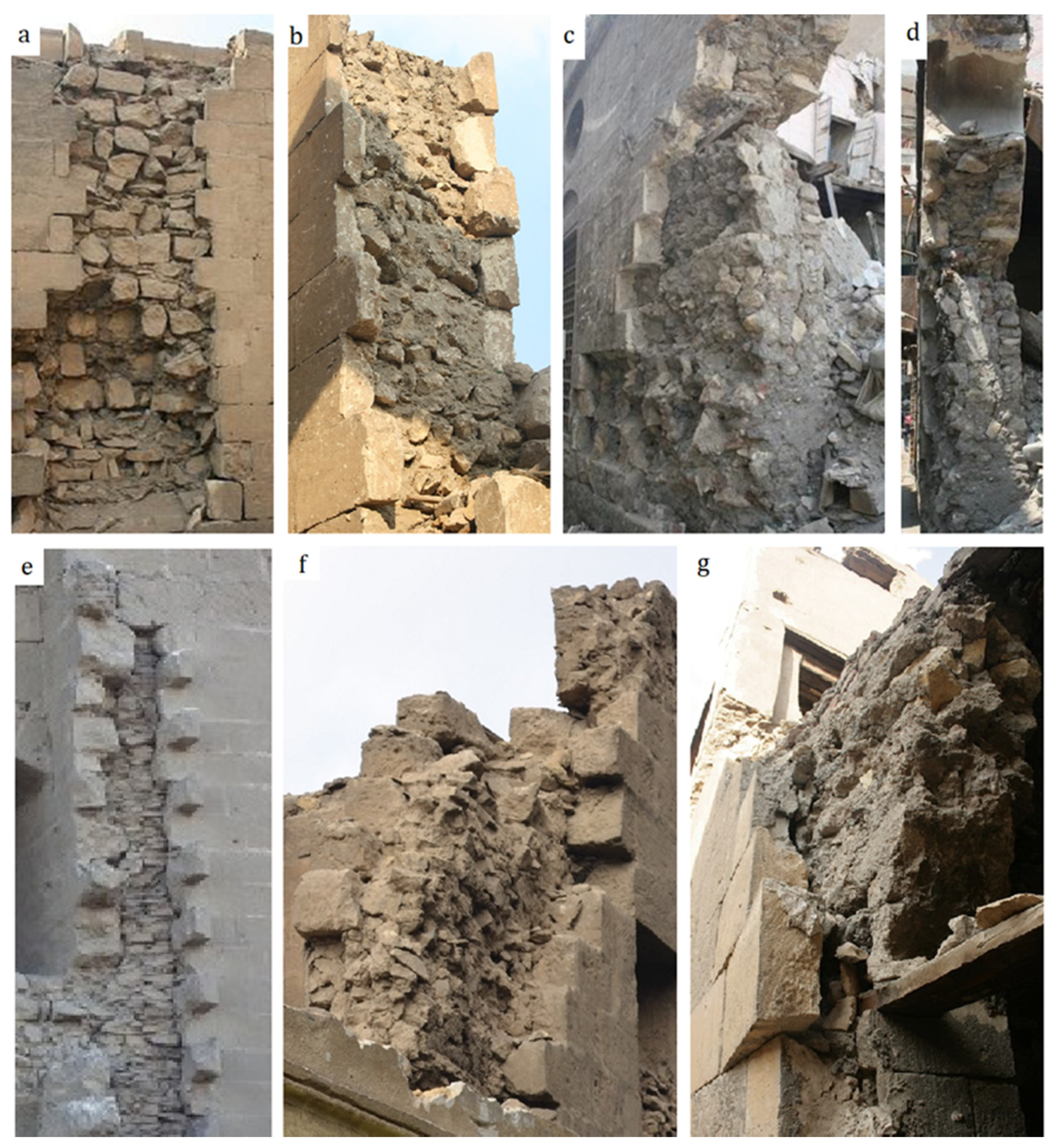
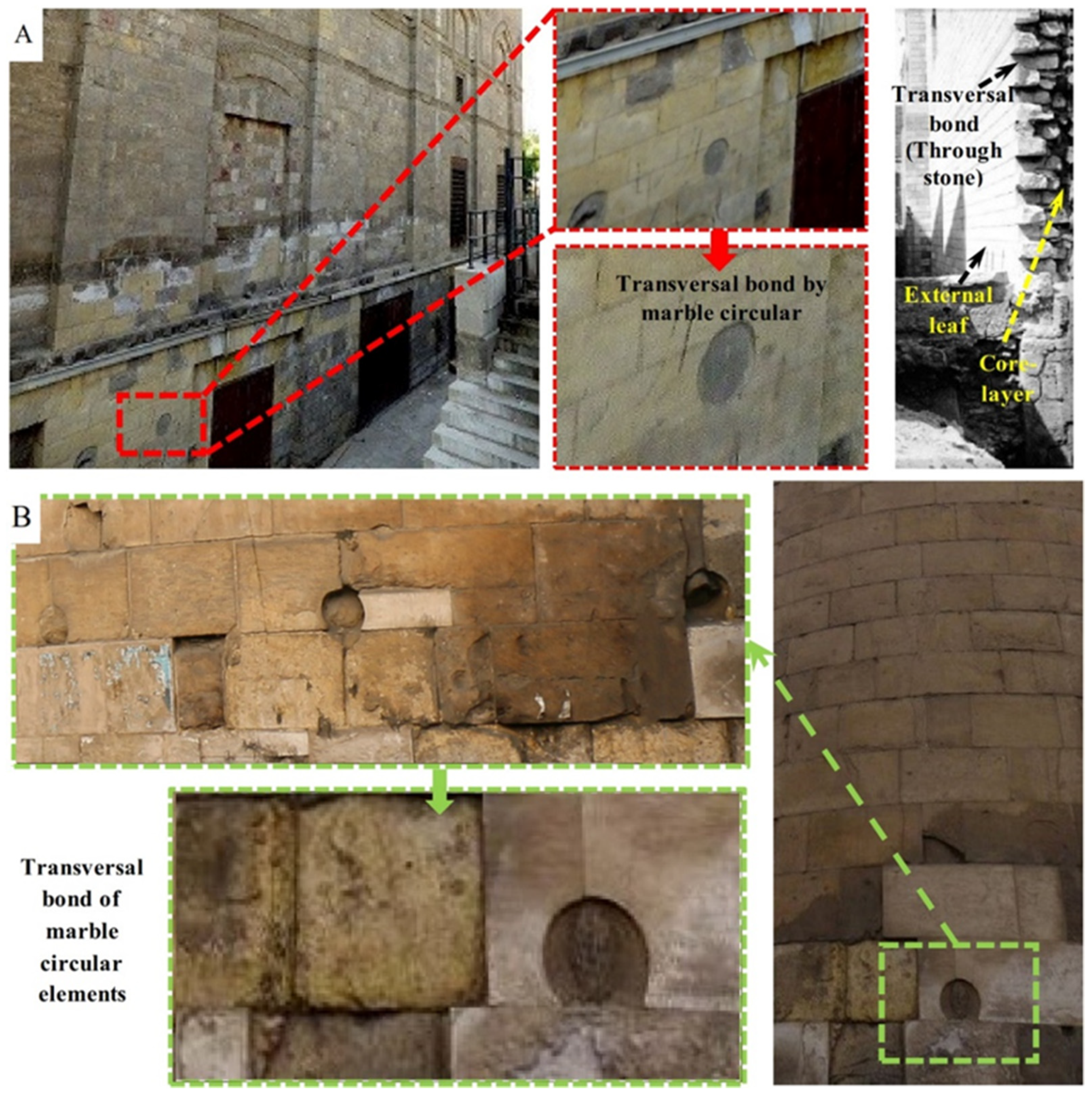
2.1. Field Survey
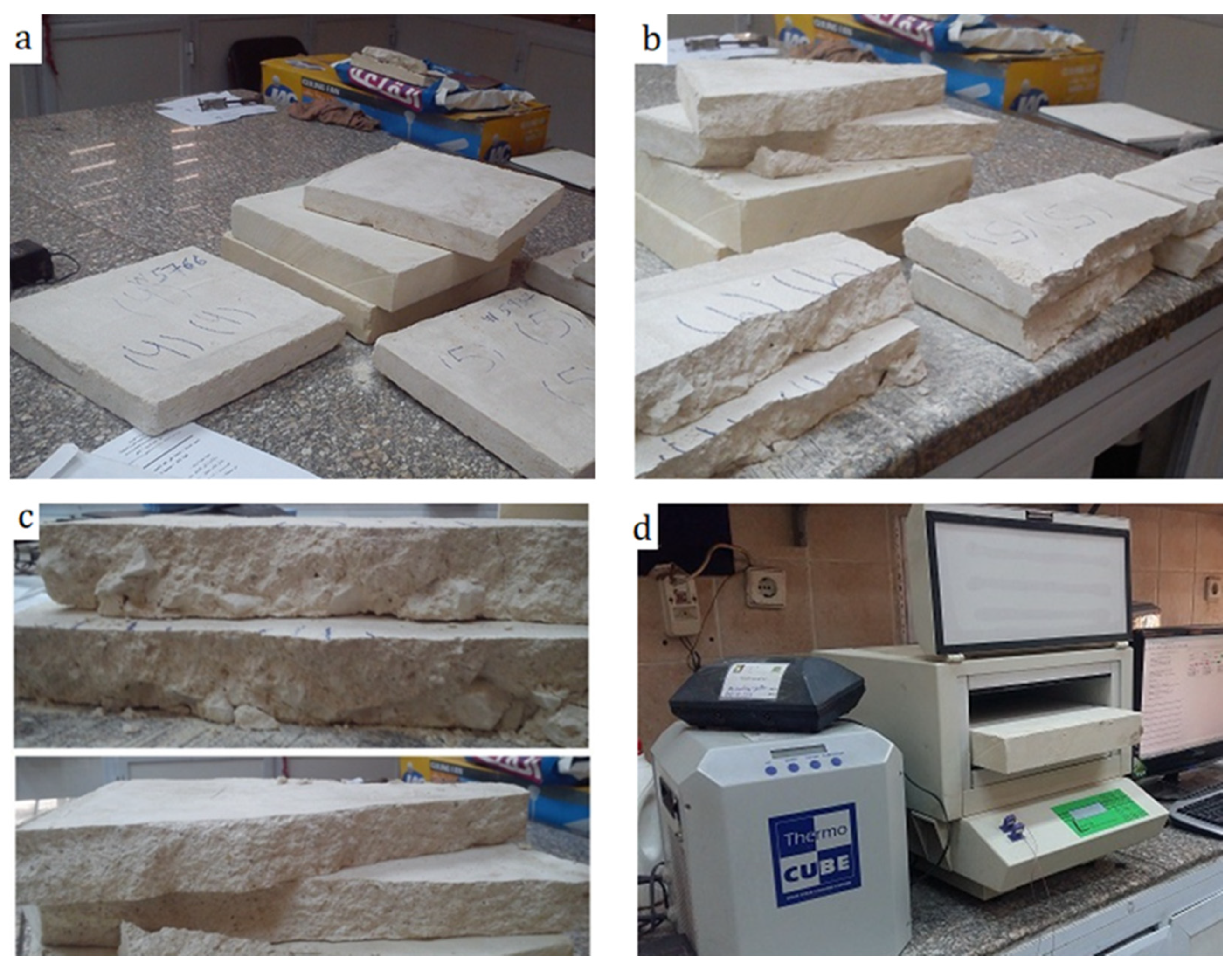
2.2. Sampling
2.3. Petrographic Investigation
2.4. Mineralogical Characterization
2.4.1. Quantitative Analysis Using X-ray Diffraction Technique (XRD)
2.4.2. Thermal Analysis (TG/DTA)
2.5. Microstructure and Micro-Morphological Examination Using SEM with EDX
2.6. Physical Characterization
2.7. Mechanical Characterization
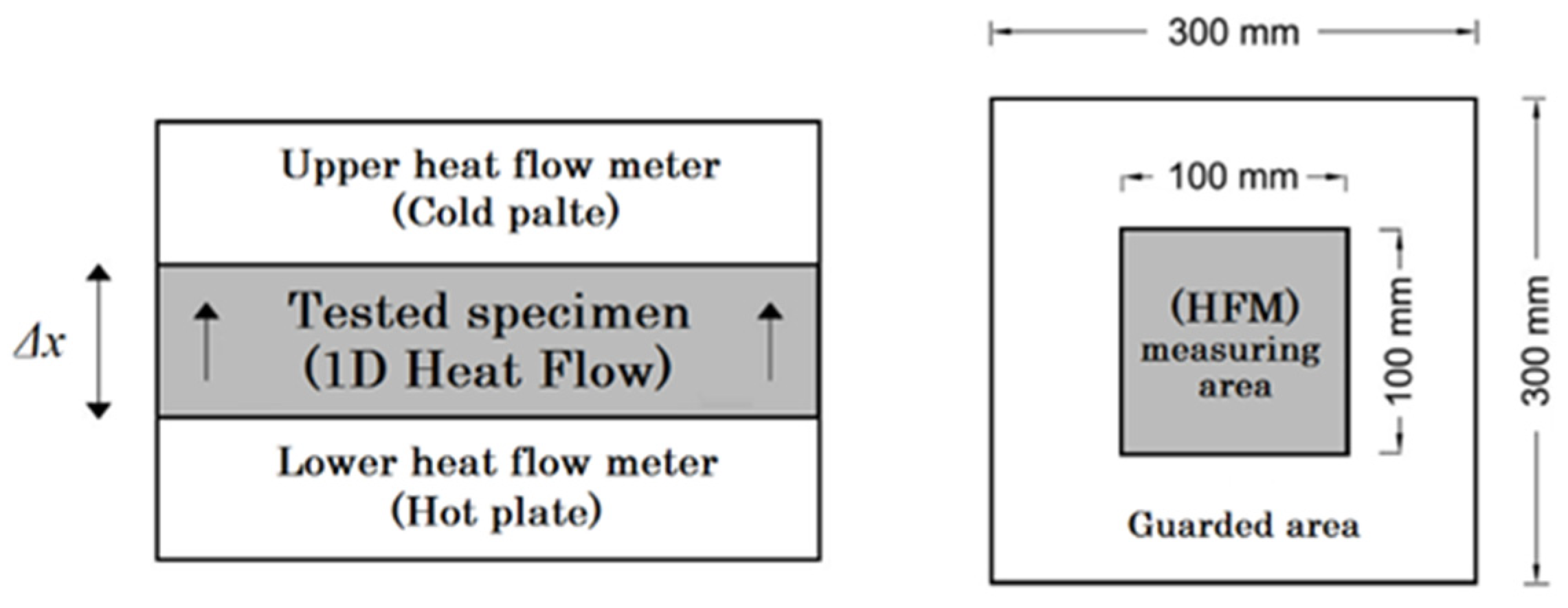
2.8. Thermal Conductivity and Resistivity
3. Results and Discussion
3.1. Characterization of the Cross-Section Morphology
3.2. Petrographic Investigation
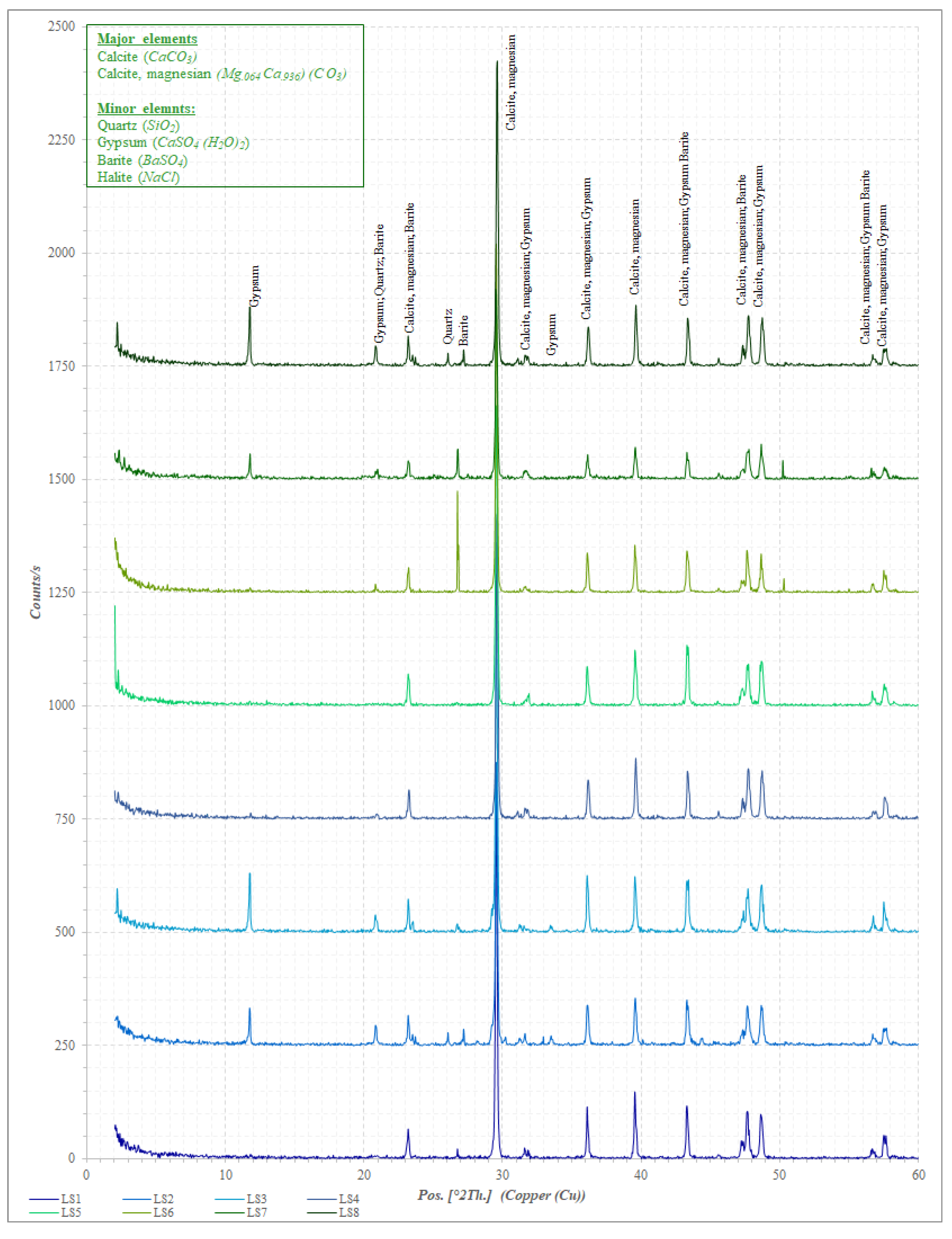
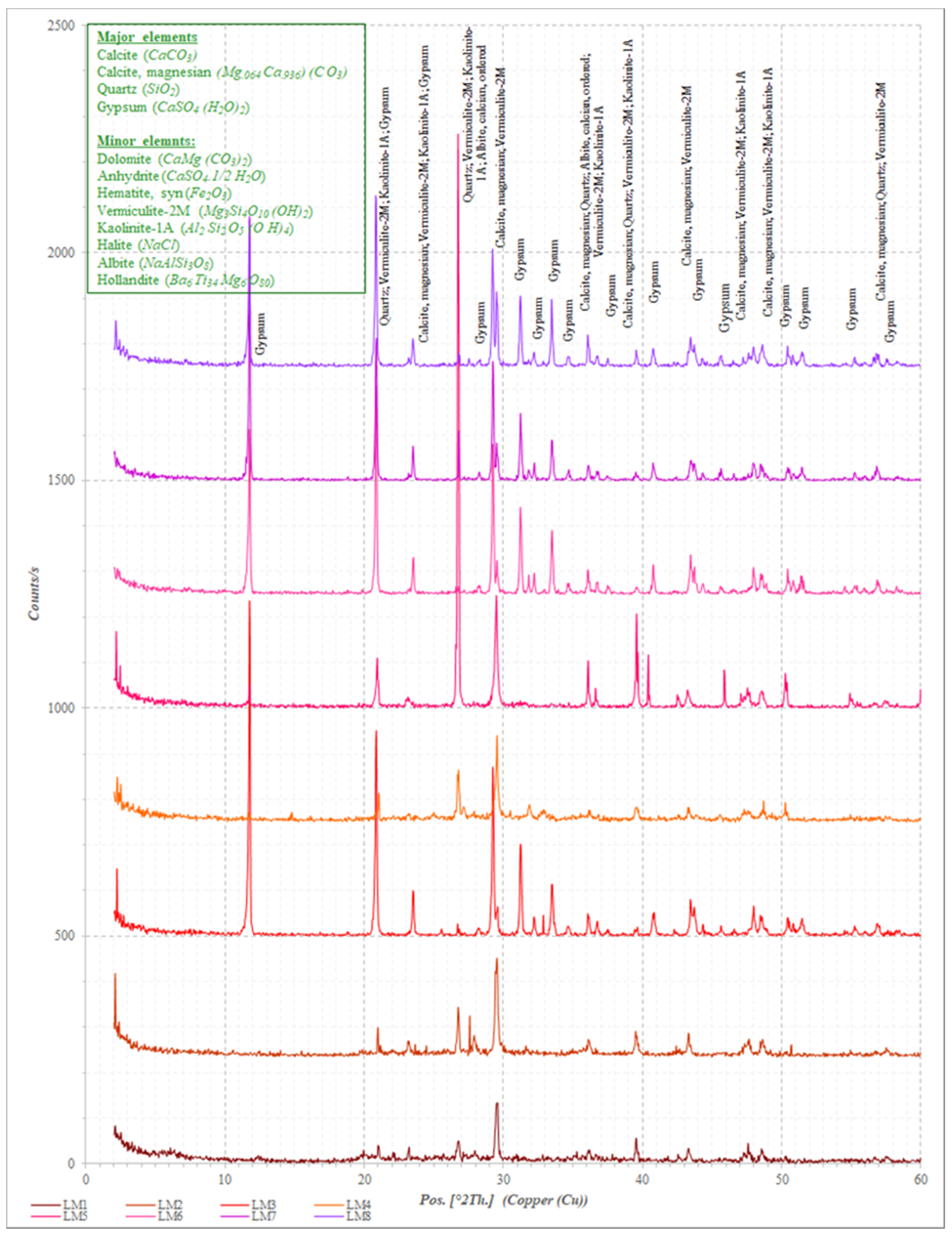
3.3. Quantitative Analysis Using X-ray Diffraction Technique (XRD)
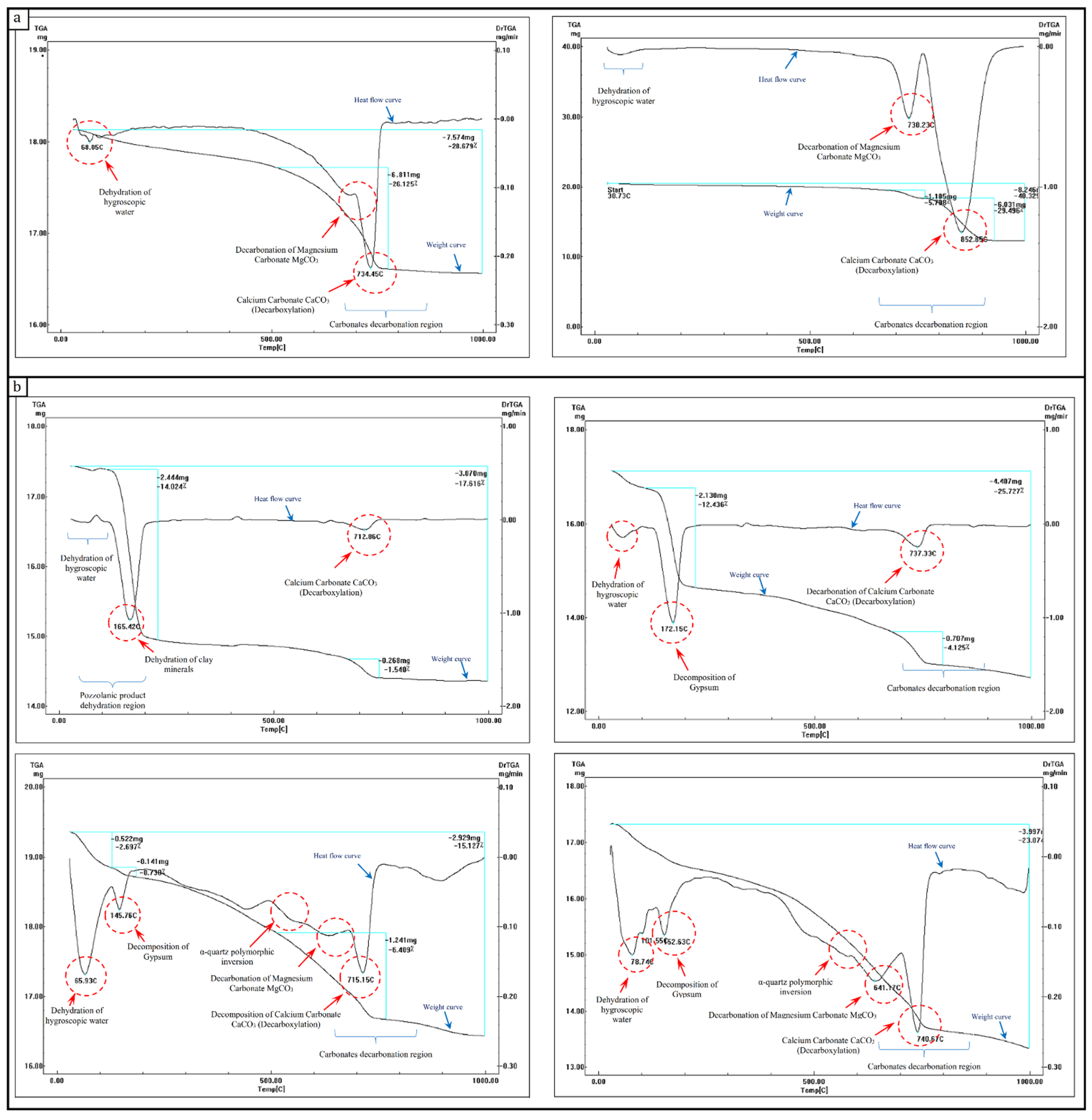
3.4. Thermal Analysis (TG/DTA)
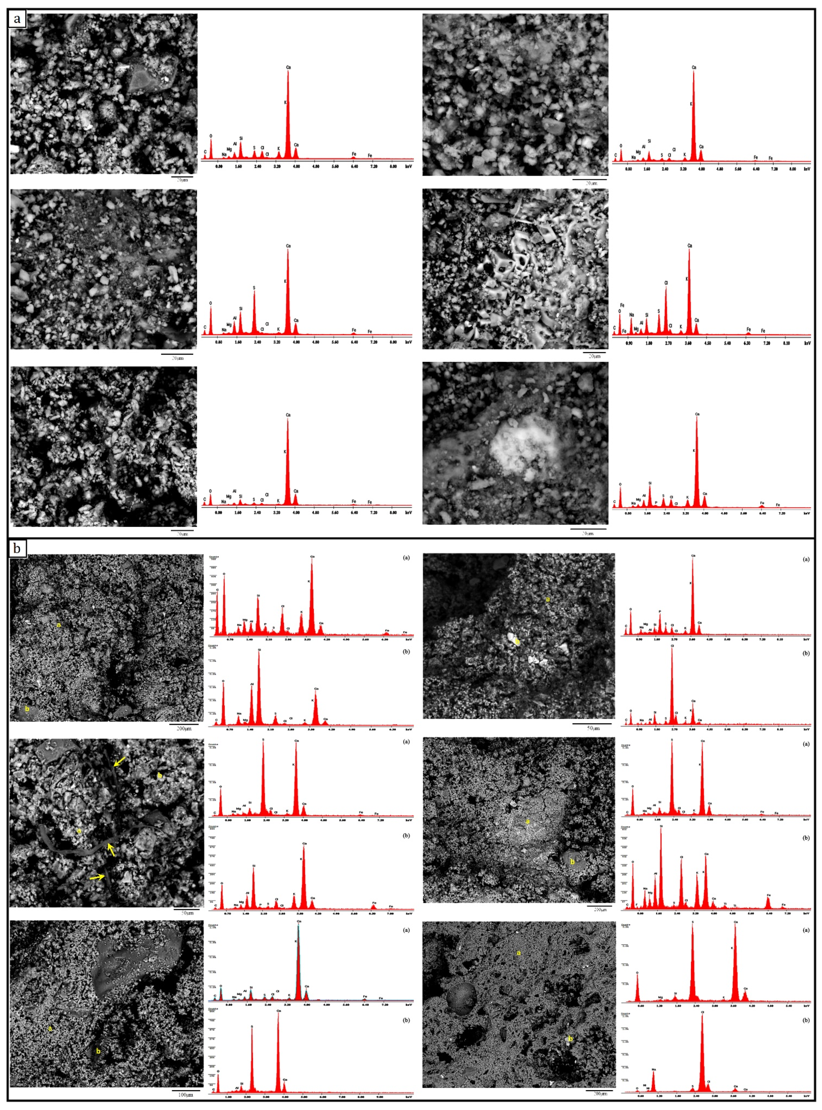
3.5. Microstructure and Micro-Morphological Examination Using SEM with EDX
3.6. Physical Characterization
3.7. Mechanical Characterization
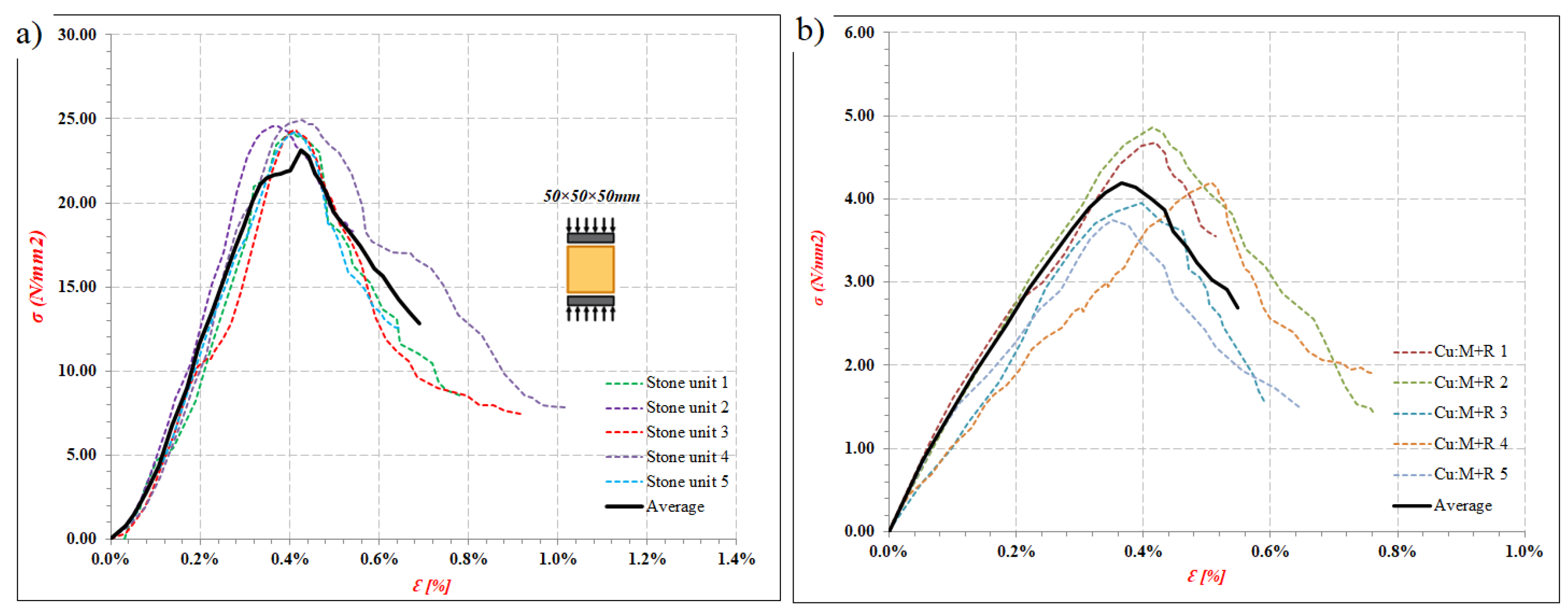
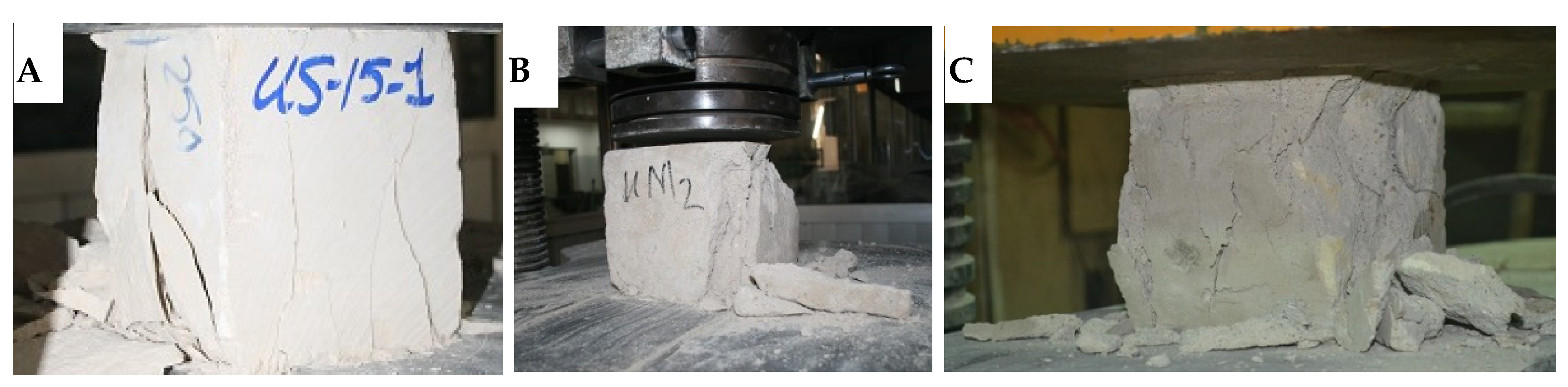
3.7.1. Uniaxial Compression Test
3.7.2. Splitting Tension Test
3.8. Thermal Conductivity and Resistivity
4. Conclusions
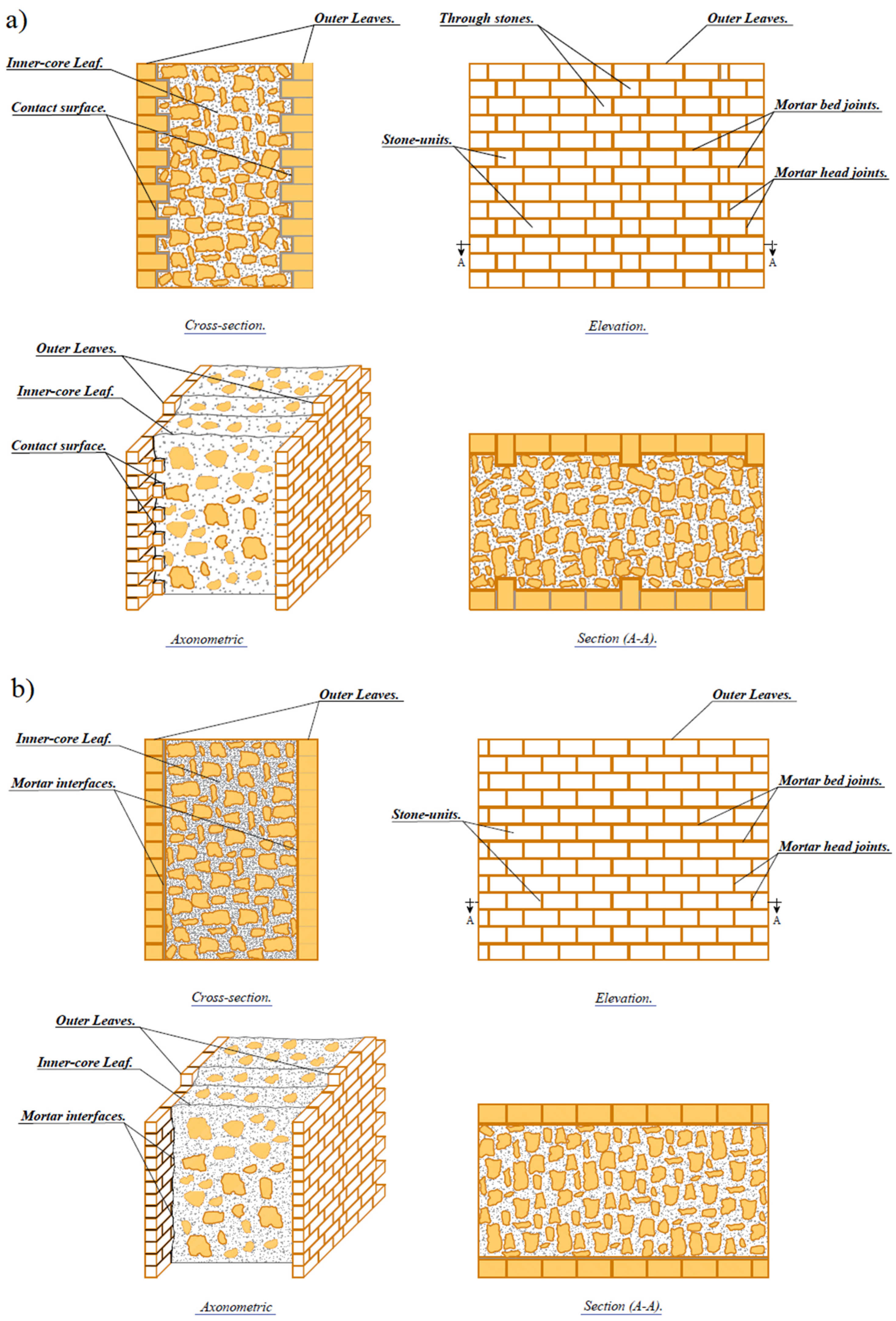
- The outer leaves of the majority of the surveyed multiple-leaf stone-masonry walls in Egypt were mainly built of limestone blocks.
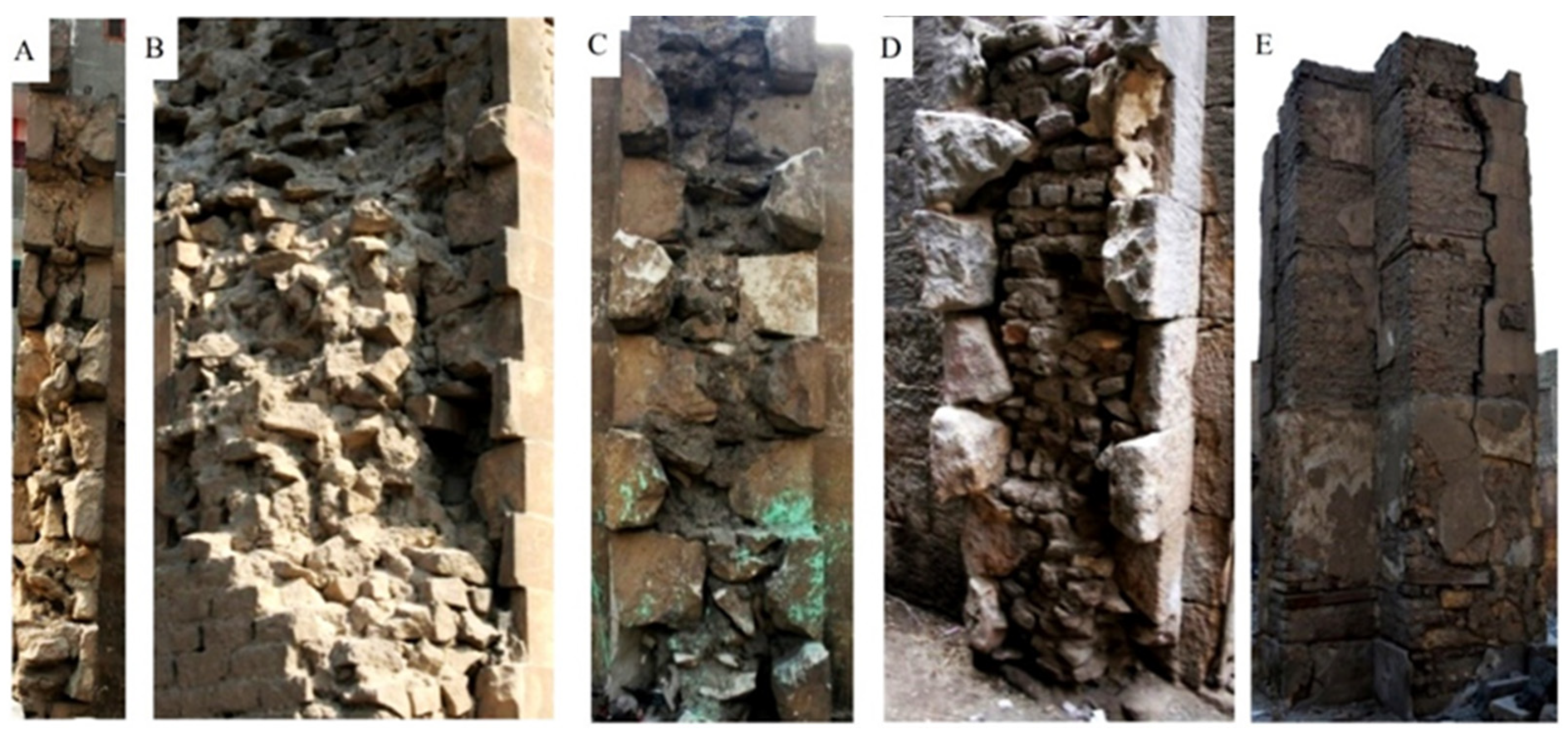
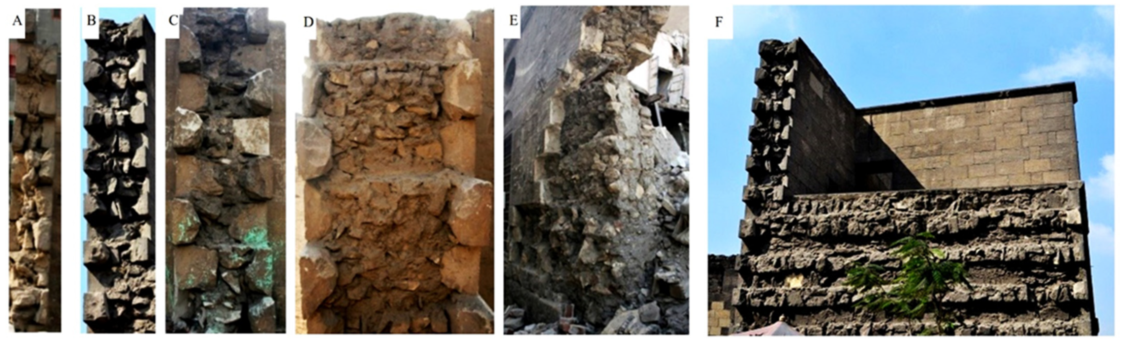
- The field survey results confirmed that most of the complex historical medieval buildings in Egypt present bearing structural elements built up by adopting multiple-leaf masonry technology. This building technology was used for vertical structural elements in almost all types of historical constructions, i.e., religious, service, residential, fortification, irrigation, etc. Moreover, multiple-leaf stone-masonry walls are characterized by different construction methods and typology that gradually changed from multiple-leaf walls with weak mechanical resistance made with a cohesionless internal core held by two separate external leaves to walls with fixed rubble-core masonry strongly connected and characterized by monolithic behaviour.
- The inner-core layer was built of rubble with bending mortar; this rubble is commonly consisting of rough and undressed limestone.
- Lime-based mortar is the most common type of mortar used in constructing both inner-core layer and external layers as a major binder between stone blocks in the case of external layers or between rubble-stones in the case of the inner-core layer.
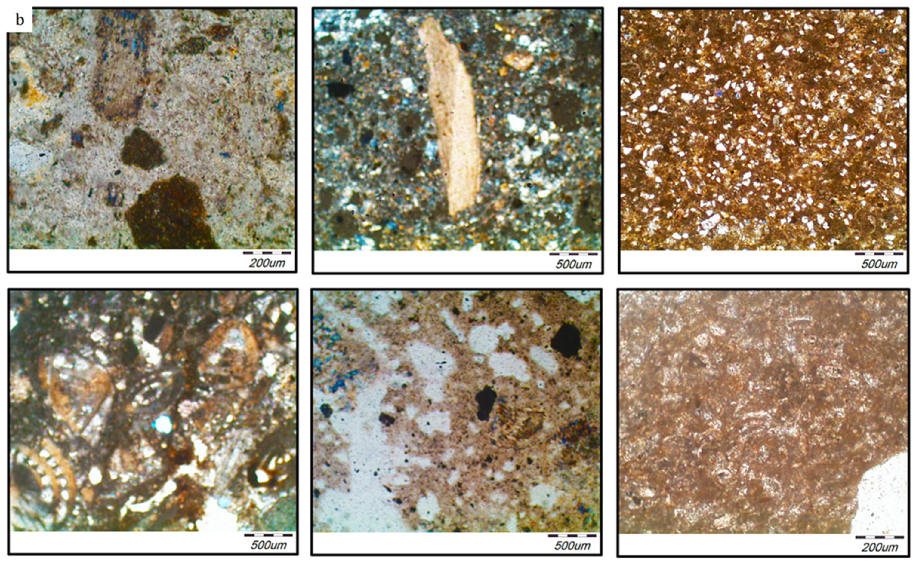
- Mortar samples, collected either from the inner or external layers, are mainly composed of lime as the major binders, with sand as an aggregate and some additives used to enhance the adhesion performance of the mortar, such as red-brick powder (i.e., Hommra) or fly ash (i.e., Qusrmil) as pozzolanic materials. Sometimes gypsum CaSO4 (H2O)2 is found with varying percentages.
- According to the results obtained by means of thermogravimetric and differential thermal analyses, the temperature corresponding to the maximum decomposition rate of the ancient lime mortar was 750 °C. Furthermore, the temperature corresponding to the maximum rate of decomposition of the historic limestone samples was 850 °C.
- According to the TGA/DTA analysis results of the lime-based mortar samples collected from the inner-core layer of different multiple-leaf stone-masonry walls, these mortars almost did not show any weight loss between 200 ° and 600 °C (related with the water of hydraulic compounds). Therefore, this could indicate that mortars have aerial lime as a binder. Moreover, some mortar samples have shown relatively low values of MgO. According to this fact, the use of magnesian-lime mortar could be proved. Moreover, the presence of magnesian calcite in the same samples has also been established by XRD.
- EDX microanalysis of various stone samples showed that the dominant constituent of the stone samples is Calcite with fine rounded Quartz crystals and, in some cases, traces of Gypsum. Additionally, the major constituent of the mortar samples is calcite with fine rounded quartz crystals. In most cases, gypsum is detected as a minor element or even trace element; conversely, in a very few cases, gypsum is detected as a significant element with calcite, particularly in walls of thicker cross-sections.
- In most cases, gypsum is detached as a minor element or even trace element in analysed mortar samples; conversely, gypsum is detached as a significant element with calcite in a few cases.
- The physical tests proved that the lime-based mortar of the embedded joints and limestone units of the outer leaves exhibit lower porosity values with an average of 24.9 and 17.2%, respectively. In contrast, the inner core layer exhibits the highest porosity values with an average of 31%; this is mainly due to the interfacial transition zone (ITZ) that exists between large particles of rubble stones and the hydrated lime-based mortar paste. Furthermore, the limestone specimens exhibit the highest dry and bulk density values, while the lime-based mortar specimens exhibit lower values, and the core-infill specimens exhibit the lowest values.
- Under uniaxial compression, a mean value of 6.8 × 10³ N/mm2 was attained for the modulus of elasticity of tested limestone specimens, while the mean values for the compressive strength obtained for limestone specimens, lime-based mortar, and core-infill cubic specimens after 120 days were 21.6, 1.6, 3.2 N/mm2, respectively. The average values of the splitting tensile strength for limestone specimens, lime-based mortar, and core-infill specimens ranged from 9 to 11.6% of the corresponding compressive strength.
- The obtained failure pattern of core-infill specimens under compression and tension confirmed that the failure mode corresponds to the loss of adhesion between the lime mortar and the stone rubbles, i.e., a weak interfacial transition zone.
- According to the thermal conductivity test results, it can be concluded that the thermal behaviour of stone-masonry walls depends on various factors. The tests results proved that the thermal conductivity of multiple-leaf masonry walls depends mainly on the density of their components and the void ratio. Consequently, the thermal resistivity of the wall can be improved by decreasing the void ratio in the infill layer, increasing the cohesion between the bedding mortar and rubble stone, and also by using stones with lower permeability. Moreover, it is possible to infer that the increase in block thickness of the external layers and, above all, the use of mortar coating, attenuate the heat transfer to the inner layer of the wall.
Author Contributions
Funding
Institutional Review Board Statement
Informed Consent Statement
Data Availability Statement
Acknowledgments
Conflicts of Interest
References
- Binda, L.; Penazzi, D.; Saisi, A. Historic masonry buildings: Necessity of a classification of structures and masonries for the adequate choice of analytical models. In Proceedings of the 6th International Symposium on Computer Methods in Structural Masonry (STRUMAS VI), Roma, Italy, 22–24 September 2003; pp. 168–173. [Google Scholar]
- Binda, L.; Cardani, G.; Saisi, A. A classification of structures and masonries for the adequate choice of repair. In Proceedings of the International RILEM Workshop on Repair Mortars for Historic Masonry, Delft, The Netherlands, 26–28 January 2005; pp. 20–34. [Google Scholar]
- Amer, O.; Abdel-Aty, Y.; Abdel-Hady, M.; Aita, D.; Torky, A.; Hussein, Y. Multiscientific-based approach to diagnosis and characterization of historic stone-masonry walls: The mausoleum of al-imam al-shafi’i, cairo (egypt). Mediterr. Archaeol. Archaeom. 2020, 20, 1–16. [Google Scholar]
- Giamundo, V. Seismic Assessment and Retrofit of Historical Masonry Barrel Vaults. Ph.D. Thesis, University of Naples Federico II, Naples, Italy, 2014. [Google Scholar]
- Bakeer, T. Collapse Analysis of Masonry Structures under Earthquake Actions. Ph.D. Thesis, Technischen Universität Dresden, Dresden, Germany, 2008. [Google Scholar]
- Drysdale, R.G.; Hamid, A.A.; Baker, L.R. Masonry Structures: Behavior and Design; de leon, B.M., Zurite, P., Handy, S., Eds.; Masonry Society, Prentice Hall: Englewood Cliffs, NJ, USA, 1999. [Google Scholar]
- Silva, B.Q.; Pappas, A.; Guedes, J.M.; da Porto, F.; Modena, C. Numerical analysis of the in-plane behaviour of three-leaf stone masonry panels consolidated with grout injection. Bull. Earthq. Eng. 2017, 15, 357–383. [Google Scholar] [CrossRef]
- Anzani, A.; Binda, L.; Fontana, A.; Henriques, J.P. An experimental investigation on multiple-leaf stone masonry. In Proceedings of the 13th International Brick and Block Masonry Conference, Amsterdam, The Netherlands, 4–7 July 2004. [Google Scholar]
- Pina-Henriques, J.; Lourenço, P.; Binda, L.; Anzani, A. Testing and modelling of multiple-leaf masonry walls under shear and compression. In Structural Analysis of Historical Constructions; Modena, C., Lourenço, P.B., Roca, P., Eds.; Taylor & Francis Group: London, UK, 2004; pp. 299–310. ISBN 04 1536 379 9. [Google Scholar]
- Capozucca, R. Historic multiple-leaf masonry wall models under compression and cyclic shear loads. In Structural Analysis of Historic Construction; D’Ayala, D., Fodde, E., Eds.; Taylor & Francis Group: London, UK, 2008; pp. 297–302. [Google Scholar]
- Magenes, G.; Penna, A.; Galasco, A.; da Paré, M. In-plane cyclic shear tests of undressed double-leaf stone masonry panels. In Proceedings of the 8th International Masonry Conference, Dresden, Germany, 4–7 July 2010. [Google Scholar]
- Silva, B.; Pigouni, A.E.; Valluzzi, M.R.; Modena, C. Calibration of analytical formulations predicting compressive strength in consolidated three-leaf masonry walls. Constr. Build. Mater. 2014, 64, 28–38. [Google Scholar] [CrossRef]
- Elmenshawi, A.; Shrive, N. Assessment of multi-wythe stone masonry subjected to seismic hazards. J. Earthq. Eng. 2015, 19, 85–106. [Google Scholar] [CrossRef]
- Aldreghetti, I.; Baraldi, D.; Boscato, G.; Cecchi, A.; Reccia, E.; Massaria, L.; Tofani, I. Damage-imperfection indicators for the assessment of multi-leaf masonry walls under different conditions. In Proceedings of the 10th International Masonry Conference, Milan, Italy, 9–11 July 2018. [Google Scholar]
- Vintzileou, E.; Miltiadou-Fezans, A.; Vrouva, A.; Anagnostopoulou, S. Mechanical Properties of Three-Leaf Stone Masonry. In Structural Analysis of Historical Constructions; Lourenço, P., Roca, P., Modena, C., Agrawal, S., Eds.; Springer: New Delhi, India, 2006; pp. 783–790. [Google Scholar]
- Lombillo, I.; Thomas, C.; Villegas, L.; Fernández-Álvarez, J.; Norambuena-Contreras, J. Mechanical characterization of rubble stone masonry walls using non and minor destructive tests. Constr. Build. Mater. 2013, 43, 266–277. [Google Scholar] [CrossRef]
- Demir, C.; Ilki, A. Characterization of the materials used in the multi-leaf masonry walls of monumental structures in Istanbul, Turkey. Constr. Build. Mater. 2014, 64, 398–413. [Google Scholar] [CrossRef]
- Meimaroglou, N.; Mouzakis, H. Mechanical properties of three-leaf masonry walls constructed with natural. Eng. Struct. 2018, 172, 869–876. [Google Scholar] [CrossRef]
- Valluzzi, M.R.; Mazzon, N.; Munari, M.; Casarin, F.; Modena, C. Effectiveness of injections evaluated by sonic tests on reduced scale multi-leaf masonry building subjected to seismic actions. In Proceedings of the NDTCE’09, Non-Destructive Testing in Civil Engineering, Nantes, France, 30 June–3 July 2009. [Google Scholar]
- Oliveira, D.V.; Silva, R.A.; Garbin, E.; Lourenco, P.B. Strengthening of three-leaf stone masonry walls: An experimental research. Mater. Struct. 2012, 45, 1259–1276. [Google Scholar] [CrossRef]
- Gemert, D.V.; Ignoul, S.; Brosens, K.; Toumbakari, E.-E. Consolidation and strengthening of historical masonry by means of mineral grouts: Grout development. Restor. Build. Monum. 2015, 21, 29–45. [Google Scholar] [CrossRef][Green Version]
- Capozucca, R. Double-leaf masonry walls under in-plane loading strengthened with GFRP/SRG strips. Eng. Struct. 2016, 128, 453–473. [Google Scholar] [CrossRef]
- Candela, M.; Borri, A.; Corradi, M.; Righetti, L. Effect of transversal steel connectors on the behaviour of rubble stonemasonry walls: Two case studies in Italy. In Proceedings of the 16th International Brick and Block Masonry Conference, Padova, Italy, 26–30 June 2016. [Google Scholar]
- Nikolopoulou, V.; Adami, C.-E.; Karagiannaki, D.; Vintzileou, E.; Miltiadou-Fezans, A. Grouts for strengthening two- and three leaf stone masonry, made with earthen mortars. Int. J. Archit. Herit. 2018, 13, 663–678. [Google Scholar] [CrossRef]
- Mahmoud, H.S. Multiscientific approach for the characterization and assessment of the degradation state of the historical Al-Shafi’i mosque walls (Jeddah, Kingdom of Saudi Arabia). Sci. Cult. 2021, 7, 1–19. [Google Scholar]
- Salama, K.K.; Ali, M.F.; Moussa, A.M. The presence of cement mortars in the added chambers of El Sakakeny Palace: A case study. Sci. Cult. 2017, 3, 25–29. [Google Scholar]
- Amer, O. Experimental and Analytical Studies on Structural Behavior of Multiple-Leaf Masonry Walls under Loads and Biological Factors, and the Appropriate Restoration Techniques with Application on Chosen Historical Islamic Buildings Biologically Affect. Master’s Thesis, Conservation Department, Faculty of Archaeology, Cairo University, Cairo, Egypt, 2018. [Google Scholar]
- Nuffield, E.W. X-ray Diffraction Methods; Wiley: Hoboken, NJ, USA, 1966. [Google Scholar]
- Warren, B.E. X-ray Diffraction; Courier Corporation: Chelmsford, MA, USA, 1969. [Google Scholar]
- Suryanarayana, C.; Norton, M.G. X-ray Diffraction: A Practical Approach; Springer Science, Business Media: New York, NY, USA, 1998. [Google Scholar]
- Williams, C.; May, R.P.; Guinier, A. Characterization of Materials; Lifshin, E., Ed.; Wiley-VCH: Weinheim, Germany, 1999. [Google Scholar]
- Waseda, Y.; Matsubara, E.; Shinoda, K. X-ray Diffraction Crystallography: Introduction, Examples and Solved Problems; Springer: Berlin/Heidelberg, Germany, 2011. [Google Scholar]
- Patel, K.P. Crystal of Metal NI(II) and CU(II) in Salicyldehyde and Ethelenediamine Solution: Preparation and Characterization. Ph.D. Thesis, Department of Physics, Suresh Gyan Vihar University, Jaipur Rajasthan, India, 2011. [Google Scholar]
- Panda, S.S.; Mohapatra, P.K.; Chaturvedi, R.K.; Kar, S.K. Chemical analysis of ancient mortar from excavation sites of Kondapur, Andhra Pradesh, India to understand the technology and ingredients. Curr. Sci. 2013, 105, 837–842. [Google Scholar]
- Theologitis, A.; Kapridaki, C.; Kallithrakas-Kontos, N.; Maravelaki-Kalaitzaki, P.; Fotiou, A. Mortar and plaster analysis as a directive to the design of compatible restoration materials in frangokastello (crete). Mediterr. Archaeol. Archaeom. 2021, 21, 109–120. [Google Scholar]
- al Sekhaneh, W.; Shiyyab, A.; Arinat, M.; Gharaibeh, N. Use of FTIR and thermogravimetric analysis of ancient mortar from The Church of the Cross in Gerasa (Jordan) for conservation purposes. Mediterr. Archaeol. Archaeom. 2020, 20, 159–174. [Google Scholar]
- Hatakeyama, T.; Quinn, F. Thermal Analysis: Fundementals and Applications to Polymer Science; John Wiley & Sons Ltd.: Hoboken, NJ, USA, 1994. [Google Scholar]
- Jones, C. The Use of Engineering Technology in the Determination of Historic Brickwork; Honors Summer Research, Tusculum Institute, Sweet Briar College: Sweet Briar, VA, USA, 2011. [Google Scholar]
- ISRM. Suggested Methods for Determining Water Content, Porosity, Density, Absorption and Related Properties and Swelling and Slake-Durability Index Properties; Brown, E.T., Ed.; Pergamon: Oxford, UK, 1981. [Google Scholar]
- ASTM D2938-95. Standard Test Method for Unconfined Compressive Strength of Intact Rock Core Specimens; ASTM International: West Conshohocken, PA, USA, 2002. [Google Scholar]
- ISRM. Suggested Method for Determining Uniaxial Compressive Strength and Deformability of Rock Materials; Brown, E.T., Ed.; Pergamon: Oxford, UK, 1981. [Google Scholar]
- Kržan, M. Performance Based Experimental and Numerical Assessment of Multi-Leaf Stone Masonry Walls. Ph.D. Thesis, Fakulteta za Gradbeništvo in Geodezijo, Univerza v Ljubljani, Ljubljana, Slovenia, 2015. [Google Scholar]
- ASTM C518-10. Standard Test Method for Steady-State Thermal Transmission Properties by Means of the Heat Flow Meter Apparatus; ASTM: West Conshohocken, PA, USA, 2003. [Google Scholar]
- EN ISO 12667. Thermal Performance of Building Materials and Products-Determination of Thermal Resistance by Means of Guarded Hot Plate and Heat Flow Meter Methods-Products of High and Medium Thermal Resistance; ISO: Geneva, Switzerland, 2001. [Google Scholar]
- ISO 8301. Thermal Insulation Determination of Steady-State Thermal Resistance and Related Properties Heat Flow Meter Apparatus; ISO: Geneva, Switzerland, 1991. [Google Scholar]
- Yüksel, N. The Review of Some Commonly Used Methods and Techniques to Measure the Thermal Conductivity of Insulation Materials. In Insulation Materials in Context of Sustainability; Almusaed, A., Almssad, A., Eds.; IntechOpen: London, UK, 2016; pp. 113–140. ISBN 978-953-51-2624-9. [Google Scholar]
- Buratti, C.; Moretti, E.; Belloni, E.; Agosti, F. Development of Innovative Aerogel Based Plasters: Preliminary Thermal and Acoustic Performance Evaluation. Sustainability 2014, 6, 5839–5852. [Google Scholar] [CrossRef]
- Giuffré, A. Mechanics of historical masonry and strengthening criteria. In Proceedings of the XV Regional Seminar on Earthquake Engineering, Ravello, Italy, 18–23 September 1989. [Google Scholar]
- Pulatsu, B.; Bretas, E.M.; Lourenco, P.B. Discrete element modeling of masonry structures: Validation and application. Geomech. Eng. 2016, 11, 563–582. [Google Scholar] [CrossRef]
- Pulatsu, B.; Gencer, F.; Erdogmus, E. Study of the effect of construction techniques on the seismic capacity of ancient dry-joint masonry towers through DEM. Eur. J. Environ. Civ. Eng. 2020, 1–18. [Google Scholar] [CrossRef]
- Frank-Kamenetskaya, O.V.; Vlasov, D.Y.; Zelenskaya, M.S.; Knauf, I.V.; Timasheva, M.A. Decaying of the marble and limestone monuments in the urban environment. Case studies from Saint Petersburg, Russia. Studia Univ. Babeş-Bolyai Geol. 2009, 54, 17–22. [Google Scholar] [CrossRef][Green Version]
- Webb, T.; Krüger, J. Differential Thermal Analysis; Mackenzie, R., Ed.; Academic Press Inc.: Cambridge, MA, USA, 1970; Volume 1, pp. 303–341. [Google Scholar]
- Montoya, C.; Lanas, J.; Arandigoyen, M.; Casado, P.G.; Alvarez, J. Mineralogical, chemical and thermal characterisations of ancient mortars of the church of Santa María de Irache monastery (Navarra, Spain). Mater. Struct. 2004, 37, 433–439. [Google Scholar] [CrossRef]
- Hatakeyama, T.; Liu, Z. Handbook of Thermal Analysis; John Wiley & Sons Ltd.: Hoboken, NJ, USA, 1998. [Google Scholar]
- Singh, N.B.; Middendorf, B. Calcium sulphate hemihydrate hydration leading to gypsum crystallization. Prog. Cryst. Growth Charact. Mater. 2007, 53, 57–77. [Google Scholar] [CrossRef]
- Gnru, R.E.; Rowlawp, R.A. Differential thermal analyses of clay minerals and other hydrous materials. Part 1. Am. Mineral. J. Earth Planet. Mater. 1942, 27, 746–761. [Google Scholar]
- Newton, R.; Sharp, J. The chemical composition of lime plasters. Cem. Concr. Res. 1987, 18, 151–155. [Google Scholar] [CrossRef]
- Alvarez, J.; Navarro, I.; Casado, P.G. Thermal, mineralogical and chemical studies of the mortars used in the cathedral of Pamplona (Spain). Thermochim. Acta 2000, 365, 177–187. [Google Scholar] [CrossRef][Green Version]
- CEN. Eurocode 6: Design of Masonry Structures; EN 1996-1-1:2003; CEN: Brussels, Belgium, 2003. [Google Scholar]
- Vasconcelos, G. Experimental Investigations on the Mechanics of Stone Masonry: Characterization of Granites and Behavior of Ancient Masonry Shear Walls. Ph.D. Thesis, University of Minho, Braga, Portugal, 2005. [Google Scholar]
- Lourenço, P.; Hees, R.; Lubelli, F.F.B. Characterization and Damage of Brick Masonry. In Structural Rehabilitation of Old Buildings; Costa, A., Guedes, J.M., Varum, H., Eds.; Springer: Berlin/Heidelberg, Germany, 2014; pp. 9–130. [Google Scholar]


| Sample No. | Minerals | Chemical Formula | Semi-Quant [%] |
|---|---|---|---|
| 1 | Calcite | CaCO3 | 79 |
| Quartz | SiO2 | 21 | |
| 2 | Calcite, magnesian | (Mg0.064 Ca0.936) (CO3) | 71 |
| Gypsum | CaSO4 (H2O)2 | 23 | |
| Barite | BaSO4 | 6 | |
| 3 | Calcite, magnesian | (Mg0.064 Ca0.936) (CO3) | 74 |
| Gypsum | CaSO4 (H2O)2 | 18 | |
| Quartz | SiO2 | 8 | |
| 4 | Calcite, magnesian | (Mg0.064 Ca0.936) (CO3) | 100 |
| 5 | Calcite, magnesian | (Mg0.064 Ca0.936) (CO3) | 85 |
| Quartz, low, syn | SiO2 | 5 | |
| Halite | NaCl | 10 | |
| 6 | Calcite, magnesian | (Mg0.064 Ca0.936) (CO3) | 77 |
| Gypsum | CaSO4 (H2O)2 | 23 | |
| 7 | Calcite, magnesian | (Mg0.064 Ca0.936) (CO3) | 71 |
| Gypsum | CaSO4 (H2O)2 | 18 | |
| Quartz | SiO2 | 11 | |
| 8 | Calcite | CaCO3 | 76 |
| Quartz, low, syn | SiO2 | 15 | |
| Halite | NaCl | 9 |
| Sample No. | Minerals | Chemical Formula | Semi-Quant [%] |
|---|---|---|---|
| 1 | Calcite, magnesian | (Mg0.064 Ca0.936) (CO3) | 39 |
| Quartz | SiO2 | 19 | |
| Vermiculite-2M | Mg3Si4O10 (OH)2 | 24 | |
| Kaolinite-1A | Al2Si2O5 (OH)4 | 18 | |
| 2 | Gypsum | CaSO4 (H2O)2 | 58 |
| Calcite | CaCO3 | 24 | |
| Quartz | SiO2 | 6 | |
| Anhydrite | CaSO4.1/2 H2O | 12 | |
| 3 | Calcite, magnesian | (Mg0.064 Ca0.936) (CO3) | 54 |
| Quartz, syn | SiO2 | 19 | |
| Albite, calcian, ordered | (Ca, Na) Al (Al, Si)3 O8 | 23 | |
| Gypsum | CaSO4 (H2O)2 | 4 | |
| 4 | Quartz | SiO2 | 92 |
| Calcite | CaCO3 | 8 | |
| 5 | Calcite | CaCO3 | 9 |
| Gypsum | CaSO4 (H2O)2 | 91 | |
| 6 | Calcite, magnesium, syn | (Mg0.064 Ca0.936) (CO3) | 51 |
| Quartz, syn | SiO2 | 38 | |
| Hematite, syn | Fe2O3 | 11 | |
| 7 | Halite | NaCl | 31 |
| Quartz | SiO2 | 56 | |
| Calcite, magnesian | (Mg0.064 Ca0.936) (CO3) | 13 | |
| 8 | Dolomite | CaMg (CO3)2 | 12 |
| Albite | NaAlSi3O8 | 33 | |
| Hollandite (Ti, Mg) | Ba6.00 Ti34.00 Mg6.00 O80.00 | 27 | |
| Calcite | CaCO3 | 8 | |
| Quartz | SiO2 | 20 |
| Sample | Mass Loss % | Total Mass Loss % | ||||
|---|---|---|---|---|---|---|
| Dehydration of Hygroscopic Water | Decomposition of Gypsum | Dehydration of Clay Minerals | α-Quartz Polymorphic Inversion | Decomposition of Carbonates | ||
| Stone | 0.227 | - | - | - | 26.125 | 28.679 |
| 0.432 | - | - | - | 35.294 | 40.329 | |
| Mortar | 2.697 | 0.730 | - | 1.251 | 6.409 | 15.127 |
| 2.135 | 12.436 | - | - | 4.125 | 25.727 | |
| 0.247 | - | 14.024 | - | 1.540 | 17.616 | |
| 2.542 | 1.834 | - | 1.254 | 7.351 | 23.074 | |
| WA | Gs | e | ||||||||||
|---|---|---|---|---|---|---|---|---|---|---|---|---|
| Avg. | CV | Avg. | CV | Avg. | CV | Avg. | CV | Avg. | CV | Avg. | CV | |
| (g/cm3) | % | (g/cm3) | % | % | % | % | % | (g/cm3) | % | % | % | |
| Limestone | 2.086 | 8.95 | 2.258 | 8.90 | 8.27 | 13.85 | 17.22 | 15.52 | 2.525 | 10.85 | 20.91 | 18.47 |
| Lime mortar | 1.811 | 16.00 | 2.060 | 14.71 | 13.97 | 38.05 | 24.90 | 38.87 | 2.444 | 18.73 | 34.99 | 48.98 |
| Core-infill | 1.715 | 2.72 | 2.025 | 4.74 | 18.10 | 30.76 | 31.00 | 30.23 | 2.528 | 14.94 | 47.45 | 47.34 |
| Tested Specimen | fc | fc,i | εci | εp | E | Et | Es |
|---|---|---|---|---|---|---|---|
| N/mm2 | N/mm2 | % | % | N/mm2 | N/mm2 | N/mm2 | |
| Limestone | 22.72 (3.10) | 6.44 | 0.11 | 0.41 | 6765.1 (7.05) | 6666.67 | 6021.50 |
| Lime-based mortar | 1.66 (4.02) | 1.23 | - | - | 1245 | - | - |
| Core-infill | 4.19 (11.02) | 0.85 | 0.05 | 0.24 | 2350.47 (16.43) | 1250 | 1142.85 |
| Specimens | Density, ρ | Temp. Upper | λ Upper | Temp. Lower | λ Lower | Percent Difference | Mean Temp. | Avg. Thermal Conductivity, λavg |
|---|---|---|---|---|---|---|---|---|
| (kg/m3) | °C | (W/m K) | °C | (W/m K) | % | °C | (W/m K) | |
| S1 | 2.2944 | 20.02 | 0.3244 | 45.03 | 0.3342 | 2.98 | 32.525 | 0.3293 |
| S2 | 2.2763 | 20.02 | 0.3572 | 45.02 | 0.3319 | 7.34 | 32.52 | 0.3445 |
| M1 | 1.6491 | 20.01 | 0.5671 | 45.02 | 0.5233 | 8.02 | 32.515 | 0.5452 |
| M2 | 1.6016 | 20.01 | 0.5752 | 45.02 | 0.5308 | 8.02 | 32.515 | 0.5535 |
| RM1 | 1.8525 | 20.02 | 0.3845 | 45.02 | 0.4178 | 8.29 | 32.520 | 0.4012 |
| RM2 | 1.8477 | 20.01 | 0.4788 | 45.02 | 0.4418 | 8.02 | 32.515 | 0.4603 |
Publisher’s Note: MDPI stays neutral with regard to jurisdictional claims in published maps and institutional affiliations. |
© 2021 by the authors. Licensee MDPI, Basel, Switzerland. This article is an open access article distributed under the terms and conditions of the Creative Commons Attribution (CC BY) license (https://creativecommons.org/licenses/by/4.0/).
Share and Cite
Amer, O.; Aita, D.; Mohamed, E.K.; Torky, A.; Shawky, A. Experimental Investigations and Microstructural Characterization of Construction Materials of Historic Multi-Leaf Stone-Masonry Walls. Heritage 2021, 4, 2390-2415. https://doi.org/10.3390/heritage4030135
Amer O, Aita D, Mohamed EK, Torky A, Shawky A. Experimental Investigations and Microstructural Characterization of Construction Materials of Historic Multi-Leaf Stone-Masonry Walls. Heritage. 2021; 4(3):2390-2415. https://doi.org/10.3390/heritage4030135
Chicago/Turabian StyleAmer, Osama, Danila Aita, Ezzeldin K. Mohamed, Akram Torky, and Ashraf Shawky. 2021. "Experimental Investigations and Microstructural Characterization of Construction Materials of Historic Multi-Leaf Stone-Masonry Walls" Heritage 4, no. 3: 2390-2415. https://doi.org/10.3390/heritage4030135
APA StyleAmer, O., Aita, D., Mohamed, E. K., Torky, A., & Shawky, A. (2021). Experimental Investigations and Microstructural Characterization of Construction Materials of Historic Multi-Leaf Stone-Masonry Walls. Heritage, 4(3), 2390-2415. https://doi.org/10.3390/heritage4030135