Article

Experimental Investigations and Microstructural Characterization of Construction Materials of Historic Multi-Leaf Stone-Masonry Walls

1
Department of Conservation, Cairo University, Giza, Cairo 12613, Egypt
2
Architecture and Design Department, University of Genoa, 16121 Genoa, Italy
3
National Water Research Centre, Construction Research Institute, Shoubra El-Kheima 13621, Egypt
4
Department of Civil Engineering, Faculty of Engineering, Cairo University, Giza, Cairo 12613, Egypt
*
Author to whom correspondence should be addressed.
Heritage 2021, 4(3), 2390-2415; https://doi.org/10.3390/heritage4030135
Submission received: 1 August 2021 / Revised: 6 September 2021 / Accepted: 7 September 2021 / Published: 14 September 2021

Abstract

:
In order to correctly define the pathology of multiple-leaf stonemasonry walls and determine the appropriate interventions for its conservation and preservation, comprehensive studies on its building materials should be carried out since the overall behaviour of masonry structures is highly dependent on the characterization of its construction materials. Consequently, an interdisciplinary procedure for construction material characterization used in multiple-leaf stone-masonry walls in Egypt has been implemented to enrich documentation, conservation and restoration issues of this type of wall. The research methodology integrates experimental data obtained through on-site sampling, conducted tests and analyses, historical information, and field survey observations. The fundamental physical and mechanical properties of the masonry elements were examined by incorporating stone blocks, mortars and core-infill materials. The mineralogical composition and interlocking textures of the collected samples were investigated utilizing a large range of complementary investigation and analysis techniques, including polarizing microscopy, X-ray diffraction (XRD), thermal analysis (TG/DTA), and environmental scanning electron microscope (ESEM) attached to an EDX unit. Through the results thus obtained, a complete characterization of the mineralogical composition; physical–mechanical, chemical, and thermal properties; and the interlocking textures of the construction materials of both the outer and inner-core layers was performed. The outer leaves of the majority of the multiple-leaf stone-masonry walls in medieval architectural heritage were mainly built of well-dressed limestone blocks with nearly uniform dimensions, while the inner-core layer was usually built of stone-rubble infill with bending lime-based mortar. The uniaxial compressive strengths of core infill (corresponding to the inner core layer) and lime-based mortar of the embedded joints are shown to be 85 and 92.5% lower than the limestone units of the outer layer, respectively. Moreover, experimental observations indicate that the inner core layer exhibits the highest porosity values; consequently, deteriorated, loose and cohesionless core infill could greatly affect the durability and thermal resistivity of this kind of wall. The results provide scientific support for investigating the overall structural behaviour of this type of walls and for decision-making in future conservation and restoration strategies.

1. Introduction

Historical buildings are considered an expression of the science, culture and history of their builders. Masonry has been used to construct the most long-lasting ancient monuments and is present in the most impressive historical structures as evidence of the spirit of enterprise of ancient cultures [1,2,3]. It is a traditional, widely used, extremely flexible and economical construction method with considerable potential for future development [4,5]. Moreover, masonry has been used to construct significant structures since the beginning of civilization for its robustness, durability and for aesthetic reasons [6].
Generally, masonry is the generic term for a composite material made of units that are usually laid in and solidly bound together, employing mortar or just friction forces between the blocks in many different arrangements. It is a heterogeneous material whose components present a relatively unknown geometry and a high mechanical variability [7]. Therefore, characterizing its construction materials is a topic of great interest as regards the accurate design of the most proper intervention techniques and materials.
The present research deals with a distinctive type of historical masonry wall, namely multiple-leaf stone-masonry (MLSM) walls (Figure 1). Most of the medieval complex historic constructions present structural elements built by adopting multiple-leaf masonry technology. This type of masonry wall is common in historic Islamic architectural heritage in Egypt, as well as in worldwide monumental structures, which identifies a non-homogeneous type of structural element.
This building technique was used for vertical structural elements in historic houses, public buildings, religious constructions, and also for piers in roads and railway bridges. The actual mechanical behaviour of such structural elements is undoubtedly affected by the low resistance in traction of the constituents, particularly as regards the weaker component. The behaviour of multi-leaf masonry walls has been reported in the literature [8,9,10,11,12,13,14], as well as material characterization of three-leaf masonry walls [3,15,16,17,18] and the utilized strengthening techniques [19,20,21,22,23,24]. The characterization and assessment of the degradation state of historical buildings, including multi-leaf masonry walls, have also been reported in the literature [3,25,26].
Through on-site observations and measurements, along with laboratory tests, a systematic survey was conducted concerning the evolution of the constructive technique and building materials utilized for multiple-leaf masonry load-bearing walls by considering historic buildings in Egypt corresponding to different eras. Different samples of the building materials used in the construction of multiple-leaf masonry walls were collected from various medieval historic buildings in Cairo, including stone blocks, mortar from bed and head joints, and filling materials. The survey’s objective was to diversify the buildings from which the samples were derived to represent the building materials used in these types of walls throughout different eras. The current experimental campaign is devoted to characterizing the construction materials used in multiple-leaf stone-masonry walls. These analyses and examinations were conducted on the masonry composing elements (stone, natural lime mortar, and core infill materials); they were aimed at accurately characterizing the main chemical, mineralogical and thermal properties of construction materials and correctly defining the pathology of multiple-leaf masonry walls in order to determine the most appropriate intervention techniques.

2. Materials and Methods

The research methodology followed in this study is divided into five tasks: (I) Mineralogical analyses through qualitative analysis using XRD and thermal analysis. These analyses are conducted for various specimens of limestone and lime-based mortars collected, during the field survey, from selected historic multiple-leaf masonry walls to determine their chemical composition and constituent minerals and compounds. (II) Petrographic investigation and thin-section analyses using polarizing microscopes in order to investigate the mineralogical composition and interlocking textures of the construction materials under examination (i.e., limestone and lime-based mortars). (III) Identification of the microstructure and morphological examinations of multiple-leaf masonry wall construction materials using environmental scanning electron microscopy (ESEM) with qualitative analysis using EDAX. (IV) Characterization of the masonry composing elements through physical and mechanical tests. (V) Thermal properties identifying the thermal behaviour, resistance and conductivity of such materials.

2.1. Field Survey

The study of the multiple-leaf masonry wall cross-sections has various aims concerning diagnosis and conservation work. One of the most significant objectives of the present field survey is to provide essential input data concerning the multiple-leaf masonry wall morphology and geometry to provide a reliable scientifically-based structural assessment that allows the formulation of valid hypotheses on its mechanical behaviour and failure mechanisms. To achieve these goals, thirty-three archaeological Islamic buildings in Cairo dating to different Islamic eras and at various locations were surveyed. Various recorded stone blocks and mortar samples were studied, while the research sources provided histories and previous documentation of some of the surveyed buildings. The conducted field survey focused on the construction technology of multiple-leaf stone-masonry walls, building materials, the overall thickness of the walls, the ratio between inner and external leaves, the composition of the inner core layer and the connectivity between the walls’ leaves. For further details of the field survey, the interested reader may refer to [3,27].

2.2. Sampling

The testing program includes extracting a set of 55 representative limestone, mortar and core-infill samples from the investigated multiple-leaf stone-masonry wall of various historic buildings in Egypt. Thirty stone samples were derived from the outer and inner layers, and fourteen mortar samples were derived from the bed and head joints of the outer layer, while eleven core-infill samples were derived from the inner core layer. All the samples here analysed and investigated were carefully collected from areas without aesthetic value or from severely damaged parts.

2.3. Petrographic Investigation

The petrographic investigation of stone and mortar samples includes determining the mineral content, grain size, micro fracturing and interlocking texture. Petrographic microscopy investigation was conducted using a Polarizing petrographic microscope on thin sections of the stone and mortar samples. Air-dried samples (at ~40 °C to avoid dehydration of components, especially Gypsum if present, and physical damage due to thermal shock) were subjected to impregnation with warmed low viscosity colour dyed epoxy resin, to aid in the visualization of pores, cracks and air voids. Very thin slices of collected samples (cut perpendicular to the bedding planes) were mounted on clear, flat glass slides. The thickness reduction (to 20–30/am) permits light to pass through crystalline or amorphous materials; this is an important aspect for the detailed analysis and recognition of the stone and mortar’s components. Morphological examination of the prepared thin sections of the stone and mortar samples was carried out using a NIKON OPTI PHOTO x23 polarized transmitted light microscope equipped with photo camera S23 under cross-polarized light XPL.

2.4. Mineralogical Characterization

Construction materials of multiple-leaf stone-masonry walls were studied by laboratory investigation. The samples collected during the field survey that were derived either from the outer leaves or inner-core layer of different historic Islamic constructions were studied as regards their mineralogical composition, which was identified by X-ray diffraction and thermal analysis as described in the following sections.

2.4.1. Quantitative Analysis Using X-ray Diffraction Technique (XRD)

The basic principles of this technique have been described in detail by [28,29,30,31,32], among others.
Mineral compositions of the collected samples were identified by means of X-ray diffraction patterns, using an XPert PR PAN analytical X-ray diffraction model with a secondary monochromator. The samples under examination were prepared for the analysis by drying at 110 °C and grinding to less than 75 mm diameter. The analysis was run using Ni-filter and Cu-Kα radiation (λ = 1.542 Å) at 45 kV, 35 MA and scanning speed 0.02° (2θ)/sec. The diffraction peaks between 2θ = 0° and 60° and corresponding spacing (d, Å) and relative intensities (I/I°) were obtained. The diffraction charts and relative intensities were obtained and compared with ICDD files.

2.4.2. Thermal Analysis (TG/DTA)

As corroborative tools, thermogravimetric analyses/differential thermal analyses (TGA/DTA) were carried out on the stone and mortar samples collected from the different multiple-leaf stone-masonry walls. The thermal analysis involves studying the evolution of several physical properties as a function of temperature. When the material is subjected to heating or cooling, its chemical composition and crystal structure undergo various changes such as reaction, oxidation, decomposition, fusion, expansion, contraction, crystallization, or phase transition. All these changes can be detected using differential thermal analysis [33]. Furthermore, thermal transformations like dehydration, dihydroxylation, oxidation, and decomposition can be revealed through thermal investigations [34].
Thermogravimetric analysis (TGA) deals with the change in the mass of a substance continuously monitored as a function of temperature or time when it is heated or cooled at a predetermined rate. It provides information on the thermal stability of the sample at different temperatures, the purity of the sample, as well as its water, carbonate, and organic content. It is also helpful for studying decomposition reactions [33]. Differential thermal and thermogravimetric analyses (TGA/DTA) are suitable to establish characteristics of the stone and mortar samples, as it is easy to detect the main components, the nature of the aggregate, and other aspects with a small quantity of sample [34,35,36] and to define the temperature at which material starts decomposing [37]. Moreover, it is also possible to know whether the decomposition occurs in one or more stages by observing the non-linear drops in the sample’s mass [33,38].
Thermal analysis experiments were performed using thermogravimetry and differential thermal analysis (DT.50 thermal analyser, Shimadzu Co., Kyoto, Japan). The stone and mortar samples to be analysed by TGA/DTA were dried and ground up to 106 μm. The experiment was carried out by heating the sample from room temperature up to 1000 °C at a rate of 10 °C/min in a static air atmosphere. The sensitivity of this equipment is 0.0001 mg with a temperature range from ambient temperature to 1000 °C.

2.5. Microstructure and Micro-Morphological Examination Using SEM with EDX

A scanning electron microscope (SEM) with an EDX (microanalysis) attachment was used to identify the structural morphology and microstructure of the collected stone and mortar samples, determine the forming minerals, and observe voids and weathering status. Energy-dispersive X-ray analysis (EDX) was used to determine the elemental composition where necessary, which proved to be complementary information to support the previous techniques employed. Qualitative analysis using EDX was performed on uncoated samples to avoid overlapping gold peaks with beaks of interest, using a higher accelerating voltage of 20 kV and a larger spot size than the imaging. EDX spectra were obtained between 0 and 10 KeV.
SEM-EDX analysis was carried out using an SEM Model Quanta 250 FEG (Field Emission Gun) attached with an EDX unit (energy dispersive X-ray analysis), with an accelerating voltage of 30 K.V, magnification of 14× up to 1,000,000×, and resolution for Gun.1n. EDX spectra were recorded in the spot-profile mode by focusing the electron beam onto specific regions of the sample. The following is a detailed SEM examination and EDX micro-analysis of the collected stone and mortar samples under investigation.

2.6. Physical Characterization

According to the previous microanalysis on the mineralogical and chemical composition of the elements of MLSM walls [3], the mortar and core-infill specimens were selected to correctly represent the physical properties of the historic construction materials. The specimens used for the physical tests were 40 ± 5 mm cubes; a total of 18 specimens were tested; six specimens were considered for each type of masonry constituent (stone, mortar and core-infill). The core infill specimens had a percentage of stone fragments of about 60–70% in volume, in accordance with the common cases observed in the conducted field survey. The physical properties included porosity (η), dry density ( ρ d ), bulk density ( ρ B u l k ), water absorption (WA), specific weight (Gs) and void ratio (e), which were determined following the procedures outlined in ISRM’s suggested methods [39].

2.7. Mechanical Characterization

In the preparation of the specimens, special care was taken to ensure parallel ends with a smooth surface and perpendicular to the longitudinal axis of the tested specimens. All specimens were oven-dried and tested in environmental laboratory conditions. The experimental campaign on the composing elements (stone, lime-based mortar and core-infill) focused on determining the uniaxial compressive and tensile strength, in accordance with the ASTM D2938 standard [40] and the suggested testing methods by [41,42], a uniaxial testing machine with a hydraulic actuator was used. The tests were carried out under displacement control at a displacement rate of 10µm/s, permitting the tracing of the softening path to avoid the explosive failures originated by the axial load control. The complete stress–strain diagrams that characterize the compressive behaviour of all specimens are the result of averaging the displacement recorded by the LVDT between the upper and lower steel plates of the testing machine.
Regarding the lime-based mortar and core-infill, the specimens were left under controlled conditions for approximately 120 days. The same lime-based mortar was used as a binder in core-infill specimens with limestone fragments as a filler. The average size of used limestone fragments is between 1 and 10 cm in diameter.

2.8. Thermal Conductivity and Resistivity

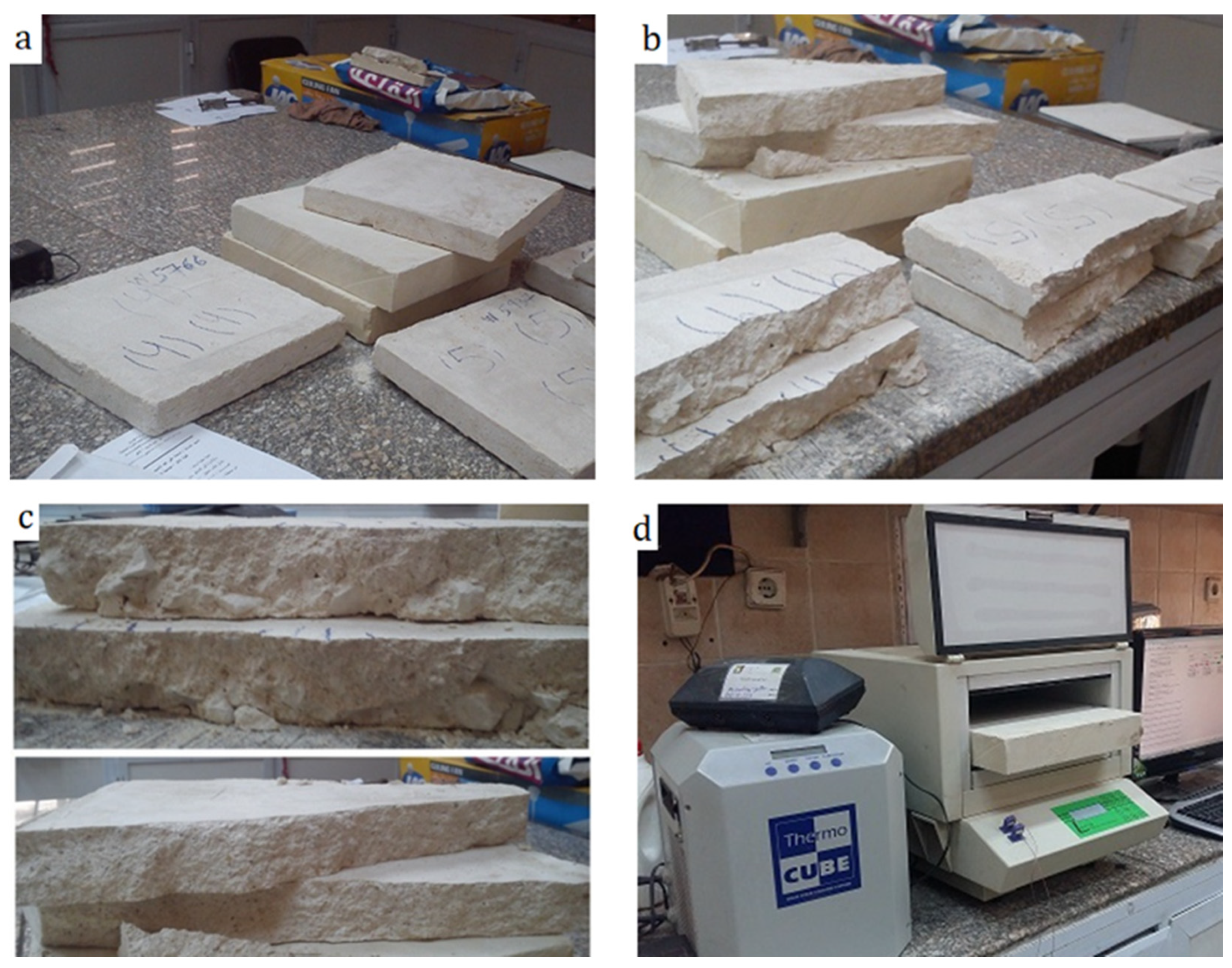
The thermal conductivity of the lime-based mortar, limestone and core infill was evaluated utilizing a heat flow meter apparatus according to [43,44,45]. All the specimens were assembled with external dimensions 300 × 300 mm due to the dimensions of the experimental apparatus (Figure 2).
Following the previously conducted microanalysis on the mineralogical and chemical composition of the stone, mortar and core-infill samples, the specimens under examination were selected to correctly represent the actual properties of the historic construction materials used in multiple-leaf masonry walls.
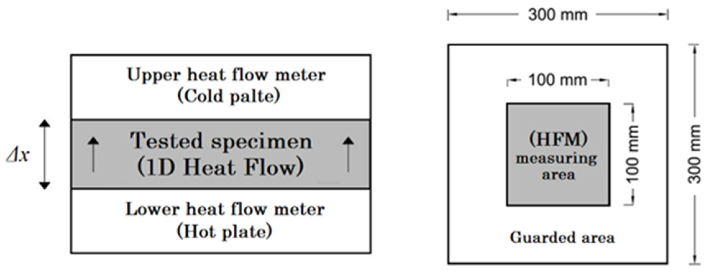
The core infill specimens had a percentage of stone fragments of about 60–70% in volume. The thermal behaviour of stone (S1, S2), mortar (M1, M2) and core-infill specimens (RM1, RM2) were investigated with a laser comp instrument (Thermo-CUBE) with a self-contained water reservoir and a mean specimen temperature range of 5 °C to 40 °C. The steady-state method was used, applying Fourier’s law of heat conduction to measure thermal conductivity. The specimens were interposed between two parallel plates (the hot guard heater and the cold plate) at constant but different temperatures. The power rate input in the hot plate with the metered area, A, is measured when thermal equilibrium is reached at steady-state conditions. When the control system is used, the plate temperatures reach stability [46]. The tested specimens with a thickness of 40 mm were placed between two flat plates controlled to a uniform one-dimensional temperature field. The temperature drop across the specimen is measured by thermocouples fixed in the plates, while the heat flow through the specimen is measured by wireless thermal flux meters (HFMs) embedded in the centre of each plate. Figure 3 illustrates a schematic diagram of the heat flow meter apparatus.
After thermal equilibrium was developed, where the heating/cooling plates were kept at stable temperatures, the thermal conductivity (λ, in W/M·K) was calculated by measuring the heat flux (Φ, in W/m2), the temperature difference across the specimen (ΔT, in °C) and the thickness of the specimen (Δx, in m) using the following unidirectional steady-state heat transfer equation (Equation (1)).
λ e f f = Φ   Δ x Δ T
where Φ is the heat flux (W/m2) flowing through the specimen, λeff is the thermal conductivity (W m−1 K−1) of the specimen, Δx is the sample thickness (m), and ΔT is the difference in temperature between the hot and cold surfaces of the specimen (°C) (ΔT = ThotTcold).

3. Results and Discussion

3.1. Characterization of the Cross-Section Morphology

Based on the collected data and field survey outcomes, most of the thick walls of the historic Islamic period were built of multiple-leaf masonry systems at the lower floor levels to acquire thicker wall sections and consequently higher weights (that increases the overall stability of the wall) at a relatively low economic cost. Moreover, the majority of the multiple leaf masonry walls had very thick sections (ranges from 0.5 to more than 6 m) with a homogeneous distribution of the regular well-dressed stone blocks with nearly constant or uniform dimensions in the external leaves (ashlars facing system). Much less homogeneous distribution of the stone-rubble units (as they were randomly cut from quarries and adhered with mortar) was often used as an infilling between the joints among the undressed and rough stone-rubble with variable joint thicknesses.
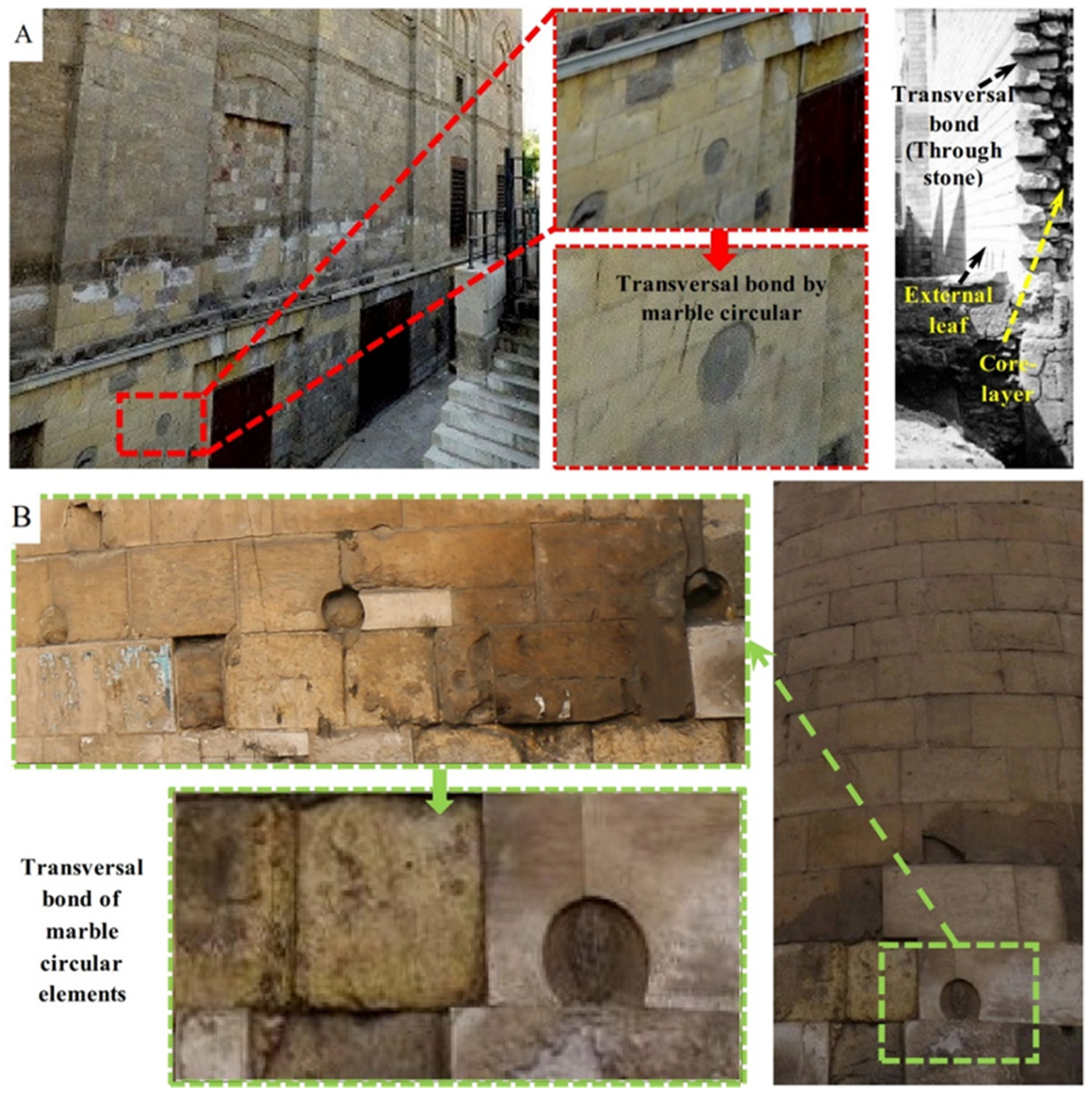
Furthermore, the external layers were usually built of well-dressed limestone blocks with nearly uniform dimensions (ashlar limestone facing system), while the dimensions of the stone-rubble infill vary according to the total thickness of the inner layer. Moreover, the joint thickness was usually much lower than the thickness of stone-rubble units in the inner core layer, and the percentage of voids and mortar in the inner-core layer is relatively low; consequently, rubble-stones settle at a high percentage. In many cases, a transversal connection between the inner and outer layers is provided by irregularly passing elements. These transversal bond elements were used to enhance the connectivity between the wall’s leaves (see Figure 4).
Moreover, adding through stones to the wall’s cross-section improves the deformation capacity, mechanical performance, and out-of-plane strength. The contribution of the transversal bond element (also referred to as through stone) to enhancing the seismic performance and capacity of unreinforced masonry walls has been studied in the literature from the experimental and computational modelling point of view [48,49,50].
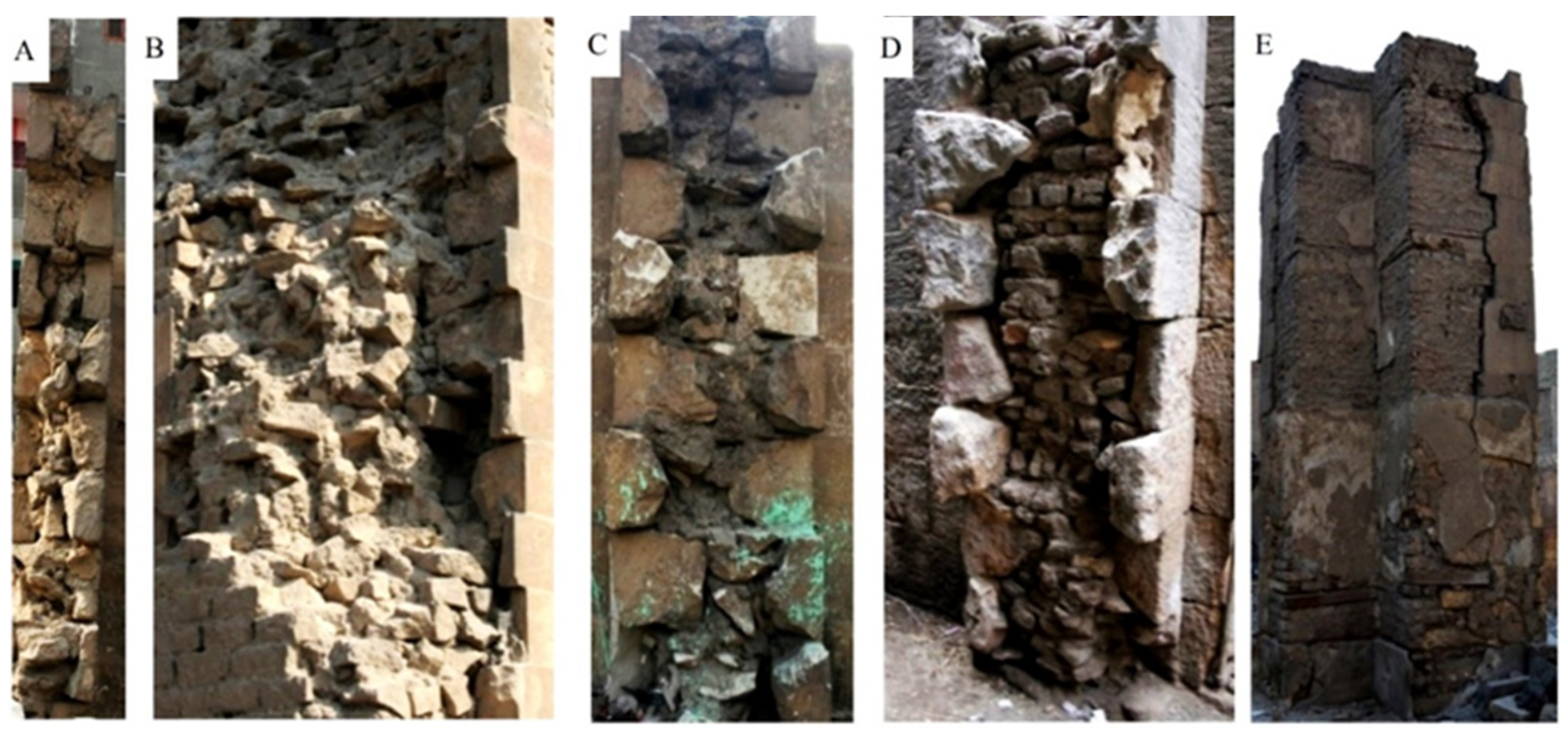
The survey results with the collected and analysed data made it possible to identify the core-infill materials of the multiple-leaf masonry walls. The core layer of the majority of these walls are built mainly of stone-rubble infill. Nevertheless, the core layer in some buildings dating back to the Ottoman period was mainly built of brick-rubble, such as Sabil Ibrahim Agha Mustahfizan and Saray Al-Musafir khana (Figure 5). Moreover, the thickness of the core layer of the majority of this kind of wall ranges from 0.5 to 2 m, and the percentage of the core layer with thickness lower than 0.5 m is about 14.5%.
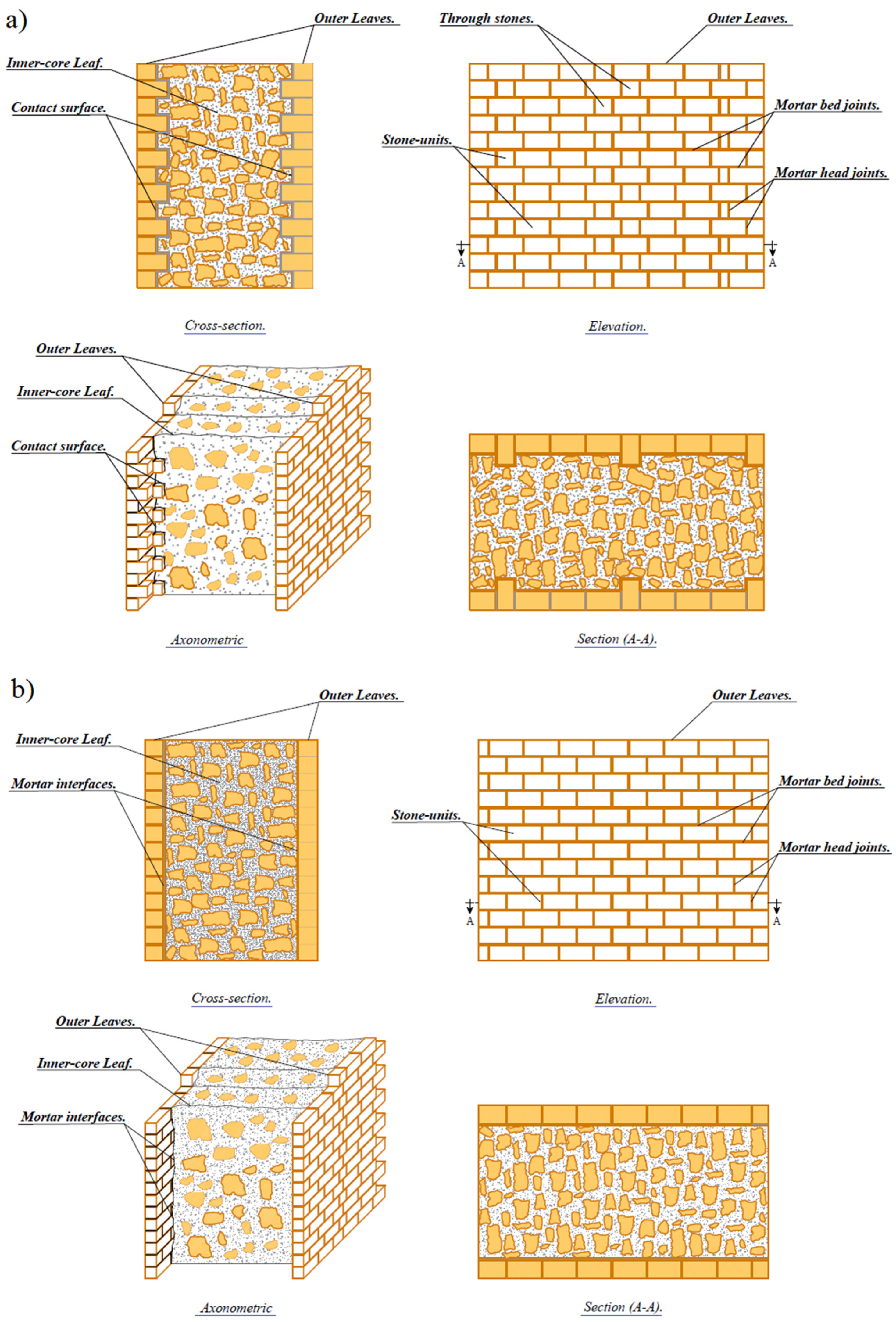
The typology of the surveyed multiple-leaf masonry walls could be characterized from the analysis of collected data and field survey results. The most frequent stone masonry typology comprises three leaves not interconnected, with the outer leaves made of well-dressed limestone blocks with nearly uniform dimensions (ashlars limestone facing system) bonded in horizontal courses. The average thickness of the walls’ cross-section is about 1 to 2 m with a thickness ratio between the external and the internal leaves of about 0.15 to 0.3 (Figure 6). The average frequency of voids percentage on core skin is around 2 to 15%. A general characterization of the common topologies of the transversal section of multiple-leaf stone-masonry walls is described in Figure 7.

3.2. Petrographic Investigation

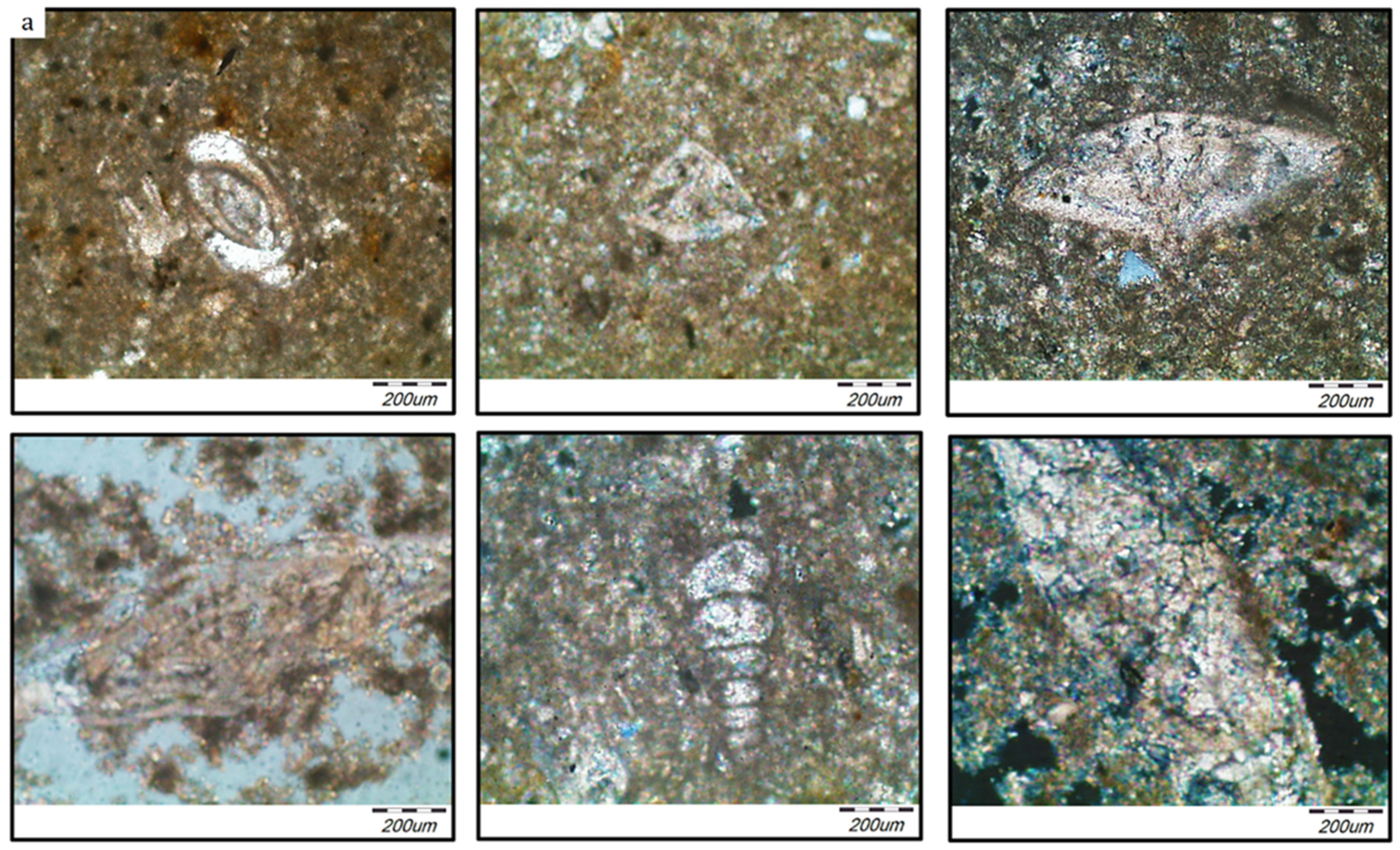
The interlocking texture and microstructure of the studied stone samples are given in Figure 8a under cross-polarized light (XPL). These samples represent limestone units derived from the external and inner layers of the investigated multiple-leaf rubble stone-masonry walls. Most of the stone units are fine-grained and composed essentially of carbonate minerals, calcite, a minor amount of dolomite, and a small amount of quartz, phosphate mineral and iron oxides. Carbonate minerals appear as very fine-grained and constitute the matrix of the stone enclosing other constituents. Many microfossils and shells of different shapes and sizes are scattered in the very fine-grained matrix of carbonate minerals and filled with recrystallized carbonate minerals. Quartz grains are very fine-grained and scattered in the stone. Some parts of the sample are slightly stained by iron oxides.
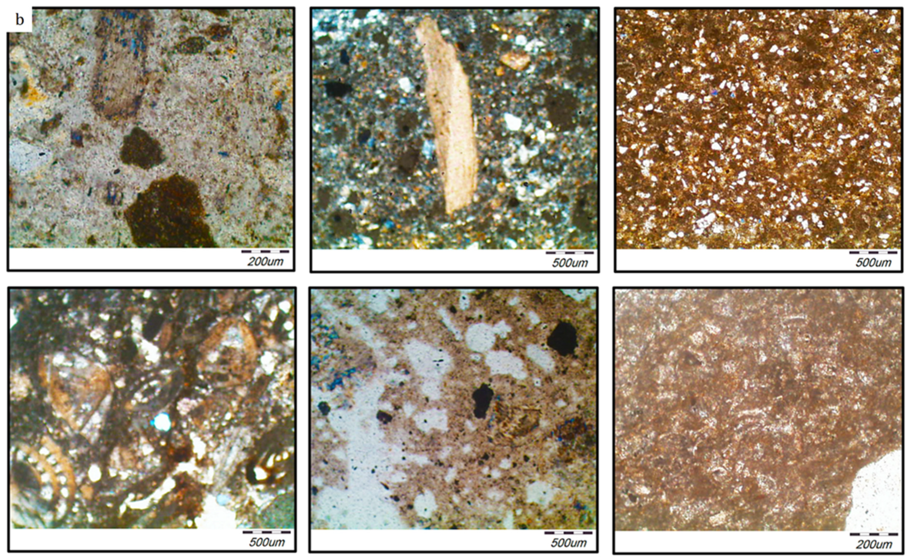
On the other hand, the interlocking texture and microstructure of the mortar samples examined here are given in Figure 8b under cross-polarized light (XPL). These samples represent mortar derived from the bed joints of the external and also from the inner layers of the investigated walls. By studying the interlocking texture of the mortar samples, it was confirmed that the mortar grains are very fine to medium-grained and composed of either only carbonate minerals or carbonate minerals and gypsum as the major components with minor amounts of quartz and clay minerals and a small amount of mica, iron oxides and opaques. Carbonate minerals occur as very fine-grained aggregates and represent the essential constituent of the mortar admixed with gypsum, while gypsum occurs as very fine to fine-grained, fibrous aggregates and is admixed with carbonates. Quartz, mica, iron oxides and opaques are scattered in a very fine matrix of carbonates. Quartz occurs as fine-grained, sub-rounded to subangular in shape and sometimes encloses mica. Opaques appear as fine-grained and scattered around the sample.

3.3. Quantitative Analysis Using X-ray Diffraction Technique (XRD)

The outer leaves of most of the surveyed multiple-leaf stone-masonry walls were mainly built of limestone blocks. In addition, the core-infill layer is built of rubble with bending mortar; this rubble commonly consists of rough and undressed limestone. According to the XRD analysis results, limestone is mainly composed of either calcite CaCO3 or calcite-magnesian (Mg0.064 Ca0.936) (CO3). Sometimes gypsum CaSO4 (H2O)2 is found at a low percentage as a result of salt decay.
According to [51], gypsum is created from the reaction of calcite (CaCO3) with sulphuric acid (H2SO4) in intensively decaying conditions under the influence of natural and anthropogenic factors such as atmospheric humidity and temperature changes, air pollution, salts, and aggressive microbial communities. This gypsum-rich patina develops as black crusts of various thicknesses and extensions. Quartz is also found at a meagre percentage (i.e., traces) as an impurity. Table 1 summarizes the average composition of the minerals for limestone samples collected from different multiple-leaf stone-masonry walls of historic Islamic buildings in Cairo.
Regarding the analysed mortar samples, the analysis results confirmed that lime-based mortar is the most common type of mortar used in the construction of both inner-core layer and external layers as a primary binder between stone-blocks, in the case of external layers, or between rubble-stones, in the case of the inner-core layer.
In accordance with the XRD analysis results, mortar samples, collected either from the inner or external layers, are mainly composed of lime as the major binders, with sand as an aggregate and some additives used to enhance the adhesion performance of the mortar, such as red-brick powder (i.e., hommra) or fly ash (i.e., qusrmil) as pozzolanic materials. Sometimes gypsum CaSO4 (H2O)2 is found in varying percentages.
The presence of gypsum in the composition of the mortar can be interpreted either as an alternative binder to lime, as an additive to lime mortar mixture enhancing the setting and hardening processes or as a result of salt decay from the reaction of calcite (CaCO3) with sulphuric acid (H2SO4) in intensively decaying conditions under the influence of natural and anthropogenic factors. Table 2 summarizes the average composition of the mortar samples collected from different multiple-leaf stone-masonry walls of historic Islamic buildings in Cairo. XRD charts related to the output results of representative stone and mortar samples are given in Figure 9 and Figure 10.

3.4. Thermal Analysis (TG/DTA)

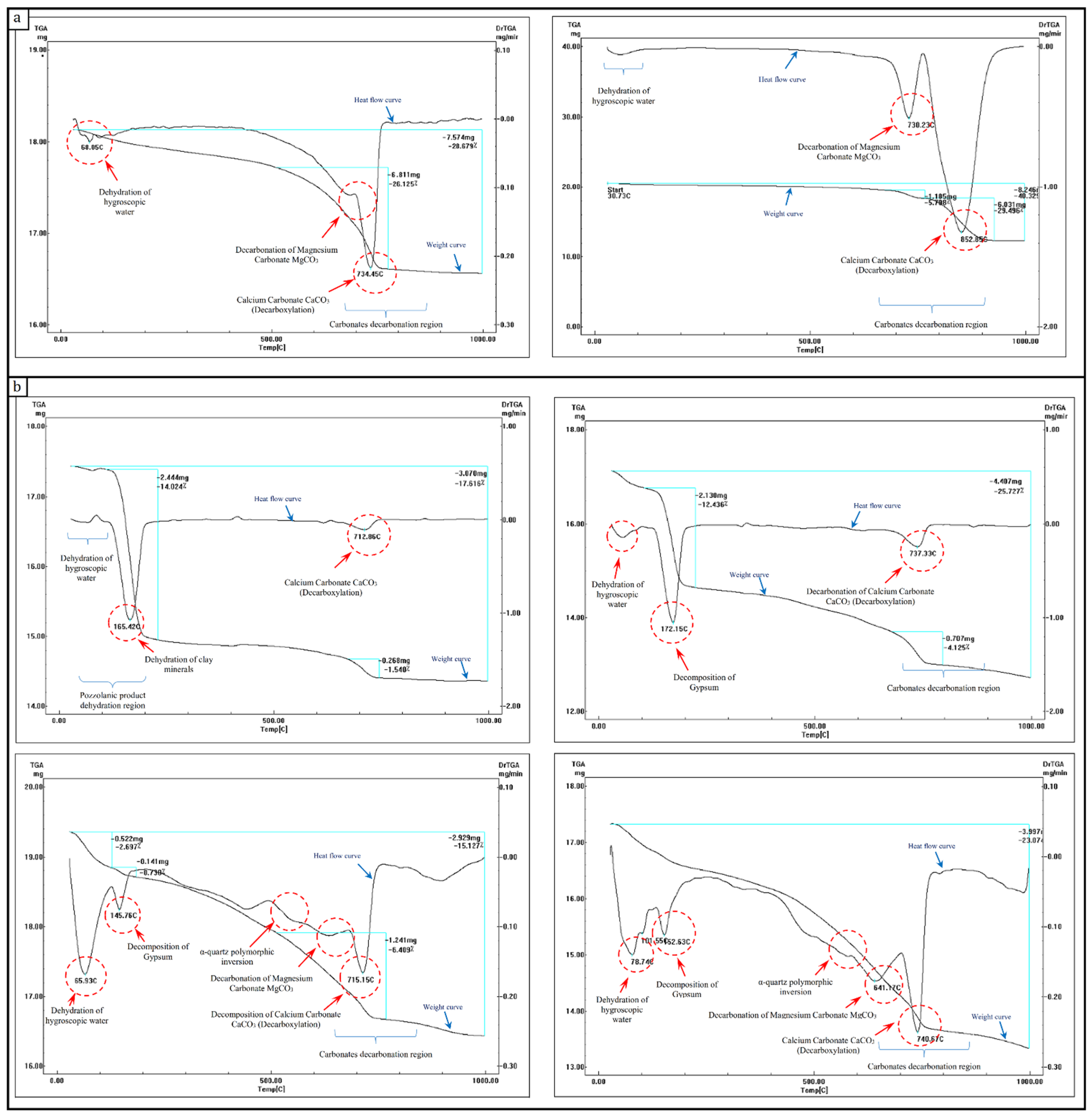
The results obtained by means of XRD have been confirmed by the thermal analyses carried out on the same investigated stone and mortar samples. According to the TGA/DTA analysis results related to stone samples, an initial weight loss of around 0.2–0.4% up to 110–120 °C is due to the release of absorbed hygroscopic water. Moreover, between 680 °C and 750 °C the obtained curve is partly erratic with little steps around 1.7–5.7%, this could be due to the presence of very small amounts of dolomite (CaMg (CO3)2) as dolomite decomposes in this temperature range [52,53]. The subsequent steps include weight loss of about 26–29.5% with decomposition at a temperature range of 650–860 °C, which can be attributed to the decarbonization of calcium carbonate (Calcite) CaCO3. At 1000 °C, meanwhile, a total weight loss of around 20.7–28.6% was registered. The thermogravimetric analysis curves for studied stone samples are shown in Figure 11a, while Table 3 represents the mass losses (in %) obtained by TGA corresponding to the dehydration of hygroscopic water and the carbonates’ decarbonization regions.
Considering the investigated mortar samples are either from the external or internal layers, an initial weight loss of around 0.24–2.6% up to 120 °C is due to the release of absorbed hygroscopic water. In addition, endothermic peaks, with associated weight loss of about 0.7–12.4% in the range of 140 °C to 200 °C, have been registered. This peak could be ascribed to the loss of water of crystallization of the gypsum (CaSO4.2H2O). Gypsum dehydration takes place in two stages as follows (Equations (2) and (3)) [54,55]:
C a S O 4 · 2 H 2 O   C a S O 4 · 1 2 H 2 O   + 3 4 H 2 O ~   145   ° C
C a S O 4 · 1 2 H 2 O   C a S O 4 + 1 2 H 2 O ~   570   ° C
In some samples, the curve shows an initial endothermic peak at 100–250 °C, due to the dehydration of clay minerals as apparent representatives of the loss of water held between the basal planes of the lattice structure (i.e., swelling water) [56].
Furthermore, an endothermic peak almost without associated weight loss is observed. This peak at ~540–570 °C could be related to the polymorphic transformation of the α-Quartz. The peak is small because the energy associated with this change is minimal (Equation (4)) [53,57].
α q u a r t z   β q u a r t z ~   540   ° C
Besides, a point of inflection at ~620 °C to 680 °C accompanied by a weight loss of about 1.2–2.7%, can be observed and ascribed to dolomite decomposition. This association is in agreement with the XRD analysis results, while the weight loss of about 4.1–6.4% in the range 620–800 °C is attributed to the decarbonization of calcite CaCO3 and the associated weight loss originates from CO2 (g) evolution (Equation (5)) [52,53,58].
C a C O 3   C a O + C O 2 ~   715   ° C
Finally, at 1000 °C a total weight loss of around 15.1–25.5% was registered. The thermogravimetric analysis curves of analysed mortar samples are shown in Figure 11b.

3.5. Microstructure and Micro-Morphological Examination Using SEM with EDX

These SEM-EDX microanalyses are remarkably compatible with the previous microanalyses, where Ca, Mg, C, and O are components of carbonate phases CaCO3, Ca Mg (CO3)2 (calcite and calcite magnesian) in XRD and thermal analyses; Si and O are components of quartz; Fe is a component of Fe2O3 (Hematite); Cl is a component of NaCl (Halite); C, S, and O are components of CaSO4.2H2O and CaSO4.1/2H2O (gypsum and anhydrite), respectively. While Al, Si, P, K, and Fe, are components of Mg3Si4O10 (OH)2, Al2 Si2 O5 (OH)4 (vermiculite and kaolinite), respectively. The presence of iron in the form of iron hydroxides in the fine limestone (micrite) determines the slightly reddish colour of the analysed limestone.
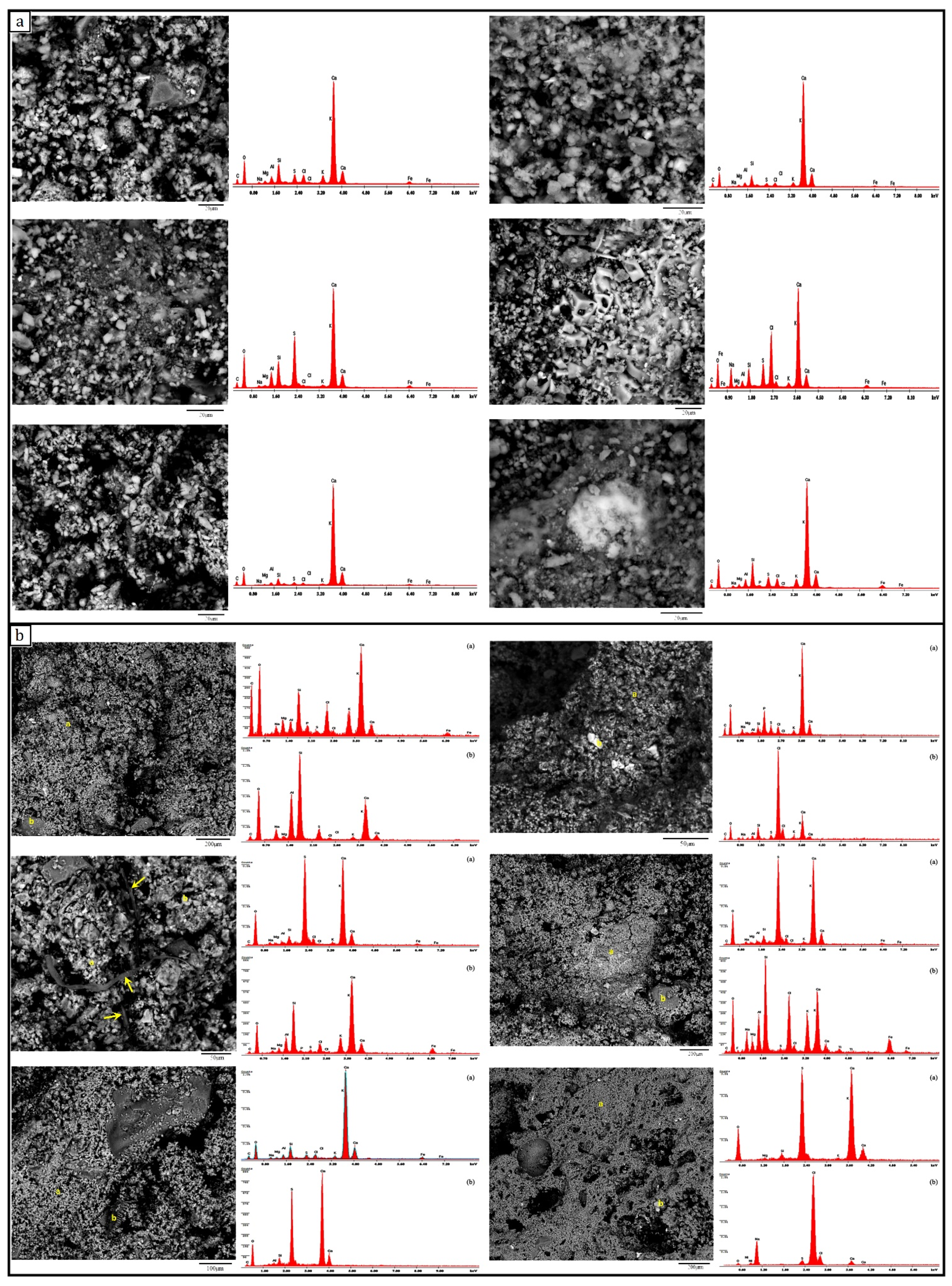
The microstructure and EDX microanalysis of various stone samples listed in Figure 12a showed that the dominant constituent of the stone samples is calcite with fine rounded quartz crystals and, in some cases, traces of gypsum. The presence of Ca, O, and Mg indicates the carbonate phases CaCO3, Ca Mg (CO3)2, while Ca, S, and O are related to the infection of the stone sample by sulphate salt decay (gypsum) CaSO4, CaSO4·2(H2O). Moreover, the presence of iron in the form of iron hydroxides in the fine limestone (micrite) determines the slightly reddish colour of the analysed limestone samples. In some samples, heterogeneous distribution of gaps and a minor quantity of crystalline salts (halite, NaCl) were noticed through the stone. Furthermore, EDX microanalysis of various mortar samples listed in Figure 12b showed that all of the analysed mortars are lime-based mortar, as the principal constituent of the mortar samples is calcite with fine rounded quartz crystals, and in most cases gypsum is detached as a minor element or even trace element; conversely, in a few cases, gypsum is detached as a significant element with calcite. Different percentages and sizes of quartz grains are scattered in the mortar.
Moreover, heavy decomposition and migration of calcite crystals were observed; besides, an inhomogeneous distribution of the gaps through the mortar was noticed. In some samples, these pores and cavities of the mortar surface were partially filled by sodium chloride precipitations as salt decay. The presence of Ca, Mg, C, and O indicates the Carbonate phases CaCO3, Ca Mg (CO3)2, while Na, S, and Cl correspond to the infection by decayed chloride and sulphate salts (e.g., NaCl and CaSo4).
Additionally, Si and O are related the quartz, while the high concentration of phosphate (P) is attributed to phosphates salts; other trace elements indicate the impurities in the mortar mixture. It is worth remarking that organic additives (i.e., chopped straw) were observed in some mortar samples derived from the inner-core layers; these organic additives were often used for strengthening the mortar and increasing its cohesion with the rubble stone to fill the inner core of the wall.

3.6. Physical Characterization

The results obtained from the experimental tests demonstrate that the limestone specimens exhibit the lowest porosity values with an average of 17.22%, while the lime-based mortar specimens, which represent the embedded joints, exhibit higher porosity values with an average of 24.90%. Moreover, the core-infill specimens corresponding to the inner layer of multiple-leaf masonry walls exhibit the highest values of porosity with an average of 31%. Furthermore, the limestone specimens exhibit the highest dry and bulk density values, while the lime-based mortar specimens exhibit lower values, and the core-infill specimens exhibit the lowest values. The average dry and bulk density values of limestone, mortar and core-infill specimens are 2.086, 1.811, 1.715 g/cm3 and 2.258, 2.060, 2.025 g/cm3, respectively. It is observed that the porosity values present some scattering opposite to density, whose average values are associated with a remarkably low coefficient of variation. The average values of the porosity (η), dry density ( ρ d ), bulk density ( ρ B u l k ), water absorption (WA), specific weight (Gs) and void ratio (e) obtained with reference to cubic specimens as well as the corresponding coefficients of variation (CV) are shown in Table 4.

3.7. Mechanical Characterization

In this section the results of the mechanical characterization of the materials are presented. Given the complexity of the topic, further details will be provided in a forthcoming paper. The notation adopted is in accordance with [7,27].

3.7.1. Uniaxial Compression Test

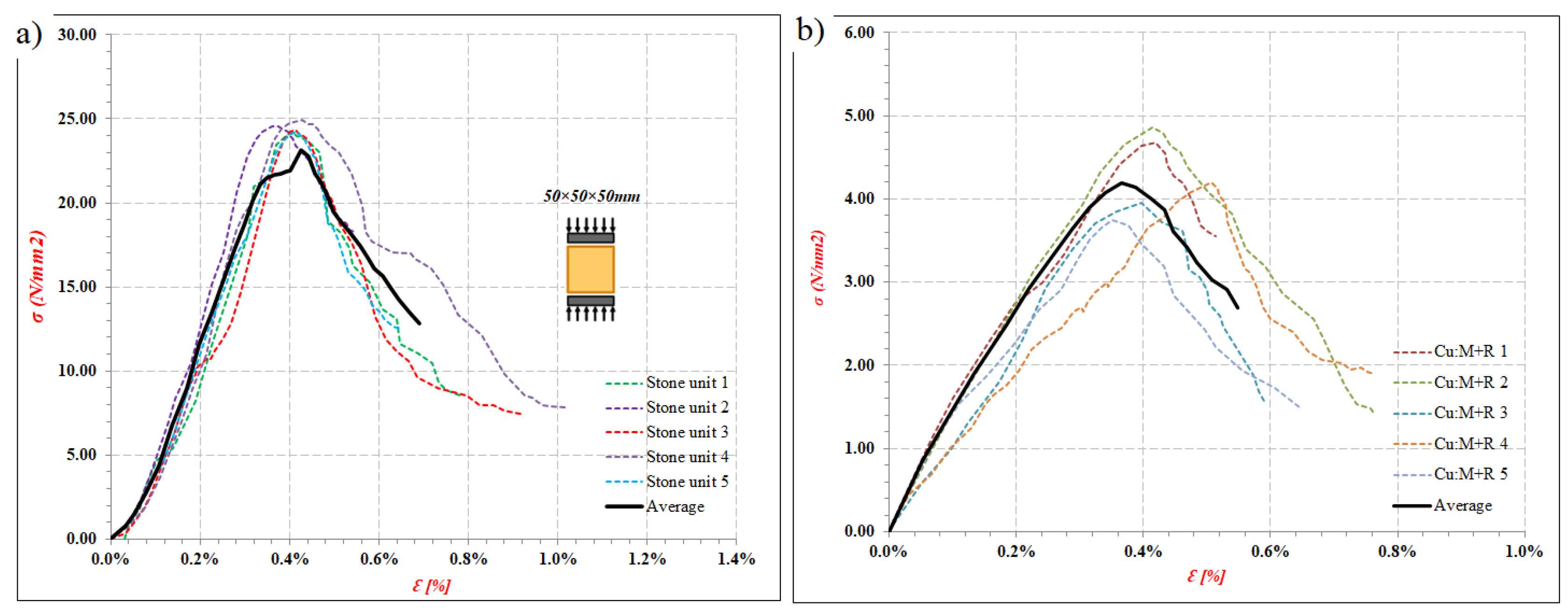
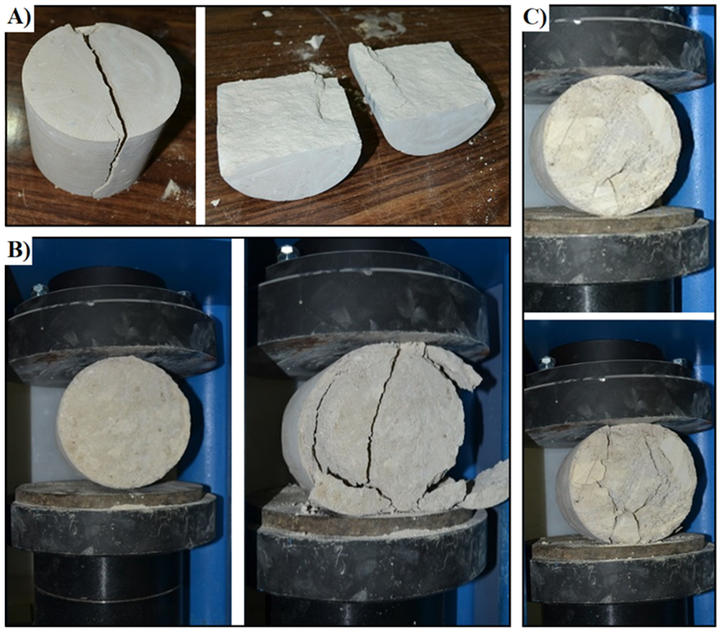
The average values of the compressive strength, fc, peak strain, εp, initial cracking stress, fc,i, initial cracking strain, εci, initial elastic modulus, Ei, tangent elastic modulus, Et, secant elastic modulus, Es, obtained in the reference specimens tested under uniaxial compression are summarized in Table 5 and Figure 13. Examples of failure patterns of the tested specimens illustrating strain localization are shown in Figure 14.
Considering limestone units, the values found for the modulus of elasticity lie on a relatively low interval, and a mean value of 6.8 E + 3 N/mm2 is attained. The compressive strength, fc,b, shows the same tendency and exhibits a relatively low range of variation (17.59–24.93 N/mm2).
Regarding the lime-based mortar, the average compressive strength of mortar specimens, fm,c, was 1.66 N/mm2 after 120 days. According to [59], the modulus of elasticity, Em, could be calculated from (Equation (6)):
E m = K E f m , c
where the recommended value for KE is 1000, however, in the literature [60,61], the KE value may range between 500 and 1000. For this reason, the value for KE was considered equal to 750; consequently, the considered average value for the modulus of elasticity, Em, is 1245 N/mm2.
The values that were obtained from testing the core-infill specimens for the modulus of elasticity lie on a relatively high interval, the minimum (1176.89 N/mm2) and the maximum (3416.06 N/mm2). By averaging the results concerning all specimens, a mean value of 2.35 × 10³ N/mm2 is attained. The compressive strength, fc,i, shows the same tendency and exhibits a relatively high range of variation (2.77–4.85 N/mm2).

3.7.2. Splitting Tension Test

According to the obtained results, average splitting tensile strength, ft,s, of 2.29, 0.148 and 0.374 N/mm2 was determined for limestone, lime-based mortar and core-infill specimens, respectively. Concerning the ratio between the tensile and compressive strengths, a value of about 10% was found for limestone, while a value of 9% was found for lime-based mortar and the core-infill. Regarding the core-infill specimens, from the visual assessment, the observed failures in the indirect tensile tests were mainly due to the loss of adhesion between the lime mortar and the stone rubble (Figure 15).

3.8. Thermal Conductivity and Resistivity

The results obtained from the conducted experimental tests demonstrate that the average thermal conductivity of limestone (corresponding to the outer layer) is about 0.365 W/mK, lime-based mortar (corresponding to the embedded joints) is about 0.549 W/mK, and core infill (corresponding to the inner layer) is about 0.402 W/mK. The density of the core infill increases when stone fragments are added so that the thermal resistivity increases by about 15.57–27.51%. Table 6 summarizes the results of thermal conductivity analysis of stone, mortar and core-infill.
According to the thermal conductivity test results, it can be concluded that the thermal behaviour of stone masonry walls depends on various factors, mainly the density of their components and the void ratio. The tests results mentioned above proved that the thermal conductivity increases as the density increases. The limestone specimens with the highest density have the highest thermal resistivity, while the core-infill specimens have a lower density and thus present lower thermal resistivity. Additionally, lime-based mortar specimens, which have the lowest density, have the most significant thermal conductivity.

4. Conclusions

Concerning the experimental investigation on the construction materials used in constructing multiple-leaf stone-masonry walls, comprehensive microanalyses and testing programs were conducted to fully characterize their mineralogical, chemical and thermal properties. The results obtained from conducted microanalyses confirmed that:
  • The outer leaves of the majority of the surveyed multiple-leaf stone-masonry walls in Egypt were mainly built of limestone blocks.
  • The field survey results confirmed that most of the complex historical medieval buildings in Egypt present bearing structural elements built up by adopting multiple-leaf masonry technology. This building technology was used for vertical structural elements in almost all types of historical constructions, i.e., religious, service, residential, fortification, irrigation, etc. Moreover, multiple-leaf stone-masonry walls are characterized by different construction methods and typology that gradually changed from multiple-leaf walls with weak mechanical resistance made with a cohesionless internal core held by two separate external leaves to walls with fixed rubble-core masonry strongly connected and characterized by monolithic behaviour.
  • The inner-core layer was built of rubble with bending mortar; this rubble is commonly consisting of rough and undressed limestone.
  • Lime-based mortar is the most common type of mortar used in constructing both inner-core layer and external layers as a major binder between stone blocks in the case of external layers or between rubble-stones in the case of the inner-core layer.
  • Mortar samples, collected either from the inner or external layers, are mainly composed of lime as the major binders, with sand as an aggregate and some additives used to enhance the adhesion performance of the mortar, such as red-brick powder (i.e., Hommra) or fly ash (i.e., Qusrmil) as pozzolanic materials. Sometimes gypsum CaSO4 (H2O)2 is found with varying percentages.
  • According to the results obtained by means of thermogravimetric and differential thermal analyses, the temperature corresponding to the maximum decomposition rate of the ancient lime mortar was 750 °C. Furthermore, the temperature corresponding to the maximum rate of decomposition of the historic limestone samples was 850 °C.
  • According to the TGA/DTA analysis results of the lime-based mortar samples collected from the inner-core layer of different multiple-leaf stone-masonry walls, these mortars almost did not show any weight loss between 200 ° and 600 °C (related with the water of hydraulic compounds). Therefore, this could indicate that mortars have aerial lime as a binder. Moreover, some mortar samples have shown relatively low values of MgO. According to this fact, the use of magnesian-lime mortar could be proved. Moreover, the presence of magnesian calcite in the same samples has also been established by XRD.
  • EDX microanalysis of various stone samples showed that the dominant constituent of the stone samples is Calcite with fine rounded Quartz crystals and, in some cases, traces of Gypsum. Additionally, the major constituent of the mortar samples is calcite with fine rounded quartz crystals. In most cases, gypsum is detected as a minor element or even trace element; conversely, in a very few cases, gypsum is detected as a significant element with calcite, particularly in walls of thicker cross-sections.
  • In most cases, gypsum is detached as a minor element or even trace element in analysed mortar samples; conversely, gypsum is detached as a significant element with calcite in a few cases.
  • The physical tests proved that the lime-based mortar of the embedded joints and limestone units of the outer leaves exhibit lower porosity values with an average of 24.9 and 17.2%, respectively. In contrast, the inner core layer exhibits the highest porosity values with an average of 31%; this is mainly due to the interfacial transition zone (ITZ) that exists between large particles of rubble stones and the hydrated lime-based mortar paste. Furthermore, the limestone specimens exhibit the highest dry and bulk density values, while the lime-based mortar specimens exhibit lower values, and the core-infill specimens exhibit the lowest values.
  • Under uniaxial compression, a mean value of 6.8 × 10³ N/mm2 was attained for the modulus of elasticity of tested limestone specimens, while the mean values for the compressive strength obtained for limestone specimens, lime-based mortar, and core-infill cubic specimens after 120 days were 21.6, 1.6, 3.2 N/mm2, respectively. The average values of the splitting tensile strength for limestone specimens, lime-based mortar, and core-infill specimens ranged from 9 to 11.6% of the corresponding compressive strength.
  • The obtained failure pattern of core-infill specimens under compression and tension confirmed that the failure mode corresponds to the loss of adhesion between the lime mortar and the stone rubbles, i.e., a weak interfacial transition zone.
  • According to the thermal conductivity test results, it can be concluded that the thermal behaviour of stone-masonry walls depends on various factors. The tests results proved that the thermal conductivity of multiple-leaf masonry walls depends mainly on the density of their components and the void ratio. Consequently, the thermal resistivity of the wall can be improved by decreasing the void ratio in the infill layer, increasing the cohesion between the bedding mortar and rubble stone, and also by using stones with lower permeability. Moreover, it is possible to infer that the increase in block thickness of the external layers and, above all, the use of mortar coating, attenuate the heat transfer to the inner layer of the wall.

Author Contributions

Conceptualization, O.A., D.A., E.K.M., A.T. and A.S.; methodology, O.A., D.A. and E.K.M.; investigation, O.A., A.T. and A.S.; visualization, O.A. and A.S.; writing—original draft preparation, O.A., E.K.M. and A.T.; writing—review and editing O.A., D.A. and A.S. All authors have read and agreed to the published version of the manuscript.

Funding

This research received no external funding.

Institutional Review Board Statement

Not applicable.

Informed Consent Statement

Not applicable.

Data Availability Statement

The data presented in this study are available on request from the corresponding author.

Acknowledgments

The authors heartily acknowledge Cairo University and the Housing & Building National Research Centre for their support. The authors are also grateful to Osama Talat, Amr Saleh, and Mustafa Bekhet for their collaboration and support.

Conflicts of Interest

The authors declare no conflict of interest.

References

  1. Binda, L.; Penazzi, D.; Saisi, A. Historic masonry buildings: Necessity of a classification of structures and masonries for the adequate choice of analytical models. In Proceedings of the 6th International Symposium on Computer Methods in Structural Masonry (STRUMAS VI), Roma, Italy, 22–24 September 2003; pp. 168–173. [Google Scholar]
  2. Binda, L.; Cardani, G.; Saisi, A. A classification of structures and masonries for the adequate choice of repair. In Proceedings of the International RILEM Workshop on Repair Mortars for Historic Masonry, Delft, The Netherlands, 26–28 January 2005; pp. 20–34. [Google Scholar]
  3. Amer, O.; Abdel-Aty, Y.; Abdel-Hady, M.; Aita, D.; Torky, A.; Hussein, Y. Multiscientific-based approach to diagnosis and characterization of historic stone-masonry walls: The mausoleum of al-imam al-shafi’i, cairo (egypt). Mediterr. Archaeol. Archaeom. 2020, 20, 1–16. [Google Scholar]
  4. Giamundo, V. Seismic Assessment and Retrofit of Historical Masonry Barrel Vaults. Ph.D. Thesis, University of Naples Federico II, Naples, Italy, 2014. [Google Scholar]
  5. Bakeer, T. Collapse Analysis of Masonry Structures under Earthquake Actions. Ph.D. Thesis, Technischen Universität Dresden, Dresden, Germany, 2008. [Google Scholar]
  6. Drysdale, R.G.; Hamid, A.A.; Baker, L.R. Masonry Structures: Behavior and Design; de leon, B.M., Zurite, P., Handy, S., Eds.; Masonry Society, Prentice Hall: Englewood Cliffs, NJ, USA, 1999. [Google Scholar]
  7. Silva, B.Q.; Pappas, A.; Guedes, J.M.; da Porto, F.; Modena, C. Numerical analysis of the in-plane behaviour of three-leaf stone masonry panels consolidated with grout injection. Bull. Earthq. Eng. 2017, 15, 357–383. [Google Scholar] [CrossRef]
  8. Anzani, A.; Binda, L.; Fontana, A.; Henriques, J.P. An experimental investigation on multiple-leaf stone masonry. In Proceedings of the 13th International Brick and Block Masonry Conference, Amsterdam, The Netherlands, 4–7 July 2004. [Google Scholar]
  9. Pina-Henriques, J.; Lourenço, P.; Binda, L.; Anzani, A. Testing and modelling of multiple-leaf masonry walls under shear and compression. In Structural Analysis of Historical Constructions; Modena, C., Lourenço, P.B., Roca, P., Eds.; Taylor & Francis Group: London, UK, 2004; pp. 299–310. ISBN 04 1536 379 9. [Google Scholar]
  10. Capozucca, R. Historic multiple-leaf masonry wall models under compression and cyclic shear loads. In Structural Analysis of Historic Construction; D’Ayala, D., Fodde, E., Eds.; Taylor & Francis Group: London, UK, 2008; pp. 297–302. [Google Scholar]
  11. Magenes, G.; Penna, A.; Galasco, A.; da Paré, M. In-plane cyclic shear tests of undressed double-leaf stone masonry panels. In Proceedings of the 8th International Masonry Conference, Dresden, Germany, 4–7 July 2010. [Google Scholar]
  12. Silva, B.; Pigouni, A.E.; Valluzzi, M.R.; Modena, C. Calibration of analytical formulations predicting compressive strength in consolidated three-leaf masonry walls. Constr. Build. Mater. 2014, 64, 28–38. [Google Scholar] [CrossRef]
  13. Elmenshawi, A.; Shrive, N. Assessment of multi-wythe stone masonry subjected to seismic hazards. J. Earthq. Eng. 2015, 19, 85–106. [Google Scholar] [CrossRef]
  14. Aldreghetti, I.; Baraldi, D.; Boscato, G.; Cecchi, A.; Reccia, E.; Massaria, L.; Tofani, I. Damage-imperfection indicators for the assessment of multi-leaf masonry walls under different conditions. In Proceedings of the 10th International Masonry Conference, Milan, Italy, 9–11 July 2018. [Google Scholar]
  15. Vintzileou, E.; Miltiadou-Fezans, A.; Vrouva, A.; Anagnostopoulou, S. Mechanical Properties of Three-Leaf Stone Masonry. In Structural Analysis of Historical Constructions; Lourenço, P., Roca, P., Modena, C., Agrawal, S., Eds.; Springer: New Delhi, India, 2006; pp. 783–790. [Google Scholar]
  16. Lombillo, I.; Thomas, C.; Villegas, L.; Fernández-Álvarez, J.; Norambuena-Contreras, J. Mechanical characterization of rubble stone masonry walls using non and minor destructive tests. Constr. Build. Mater. 2013, 43, 266–277. [Google Scholar] [CrossRef]
  17. Demir, C.; Ilki, A. Characterization of the materials used in the multi-leaf masonry walls of monumental structures in Istanbul, Turkey. Constr. Build. Mater. 2014, 64, 398–413. [Google Scholar] [CrossRef]
  18. Meimaroglou, N.; Mouzakis, H. Mechanical properties of three-leaf masonry walls constructed with natural. Eng. Struct. 2018, 172, 869–876. [Google Scholar] [CrossRef]
  19. Valluzzi, M.R.; Mazzon, N.; Munari, M.; Casarin, F.; Modena, C. Effectiveness of injections evaluated by sonic tests on reduced scale multi-leaf masonry building subjected to seismic actions. In Proceedings of the NDTCE’09, Non-Destructive Testing in Civil Engineering, Nantes, France, 30 June–3 July 2009. [Google Scholar]
  20. Oliveira, D.V.; Silva, R.A.; Garbin, E.; Lourenco, P.B. Strengthening of three-leaf stone masonry walls: An experimental research. Mater. Struct. 2012, 45, 1259–1276. [Google Scholar] [CrossRef] [Green Version]
  21. Gemert, D.V.; Ignoul, S.; Brosens, K.; Toumbakari, E.-E. Consolidation and strengthening of historical masonry by means of mineral grouts: Grout development. Restor. Build. Monum. 2015, 21, 29–45. [Google Scholar] [CrossRef] [Green Version]
  22. Capozucca, R. Double-leaf masonry walls under in-plane loading strengthened with GFRP/SRG strips. Eng. Struct. 2016, 128, 453–473. [Google Scholar] [CrossRef]
  23. Candela, M.; Borri, A.; Corradi, M.; Righetti, L. Effect of transversal steel connectors on the behaviour of rubble stonemasonry walls: Two case studies in Italy. In Proceedings of the 16th International Brick and Block Masonry Conference, Padova, Italy, 26–30 June 2016. [Google Scholar]
  24. Nikolopoulou, V.; Adami, C.-E.; Karagiannaki, D.; Vintzileou, E.; Miltiadou-Fezans, A. Grouts for strengthening two- and three leaf stone masonry, made with earthen mortars. Int. J. Archit. Herit. 2018, 13, 663–678. [Google Scholar] [CrossRef]
  25. Mahmoud, H.S. Multiscientific approach for the characterization and assessment of the degradation state of the historical Al-Shafi’i mosque walls (Jeddah, Kingdom of Saudi Arabia). Sci. Cult. 2021, 7, 1–19. [Google Scholar]
  26. Salama, K.K.; Ali, M.F.; Moussa, A.M. The presence of cement mortars in the added chambers of El Sakakeny Palace: A case study. Sci. Cult. 2017, 3, 25–29. [Google Scholar]
  27. Amer, O. Experimental and Analytical Studies on Structural Behavior of Multiple-Leaf Masonry Walls under Loads and Biological Factors, and the Appropriate Restoration Techniques with Application on Chosen Historical Islamic Buildings Biologically Affect. Master’s Thesis, Conservation Department, Faculty of Archaeology, Cairo University, Cairo, Egypt, 2018. [Google Scholar]
  28. Nuffield, E.W. X-ray Diffraction Methods; Wiley: Hoboken, NJ, USA, 1966. [Google Scholar]
  29. Warren, B.E. X-ray Diffraction; Courier Corporation: Chelmsford, MA, USA, 1969. [Google Scholar]
  30. Suryanarayana, C.; Norton, M.G. X-ray Diffraction: A Practical Approach; Springer Science, Business Media: New York, NY, USA, 1998. [Google Scholar]
  31. Williams, C.; May, R.P.; Guinier, A. Characterization of Materials; Lifshin, E., Ed.; Wiley-VCH: Weinheim, Germany, 1999. [Google Scholar]
  32. Waseda, Y.; Matsubara, E.; Shinoda, K. X-ray Diffraction Crystallography: Introduction, Examples and Solved Problems; Springer: Berlin/Heidelberg, Germany, 2011. [Google Scholar]
  33. Patel, K.P. Crystal of Metal NI(II) and CU(II) in Salicyldehyde and Ethelenediamine Solution: Preparation and Characterization. Ph.D. Thesis, Department of Physics, Suresh Gyan Vihar University, Jaipur Rajasthan, India, 2011. [Google Scholar]
  34. Panda, S.S.; Mohapatra, P.K.; Chaturvedi, R.K.; Kar, S.K. Chemical analysis of ancient mortar from excavation sites of Kondapur, Andhra Pradesh, India to understand the technology and ingredients. Curr. Sci. 2013, 105, 837–842. [Google Scholar]
  35. Theologitis, A.; Kapridaki, C.; Kallithrakas-Kontos, N.; Maravelaki-Kalaitzaki, P.; Fotiou, A. Mortar and plaster analysis as a directive to the design of compatible restoration materials in frangokastello (crete). Mediterr. Archaeol. Archaeom. 2021, 21, 109–120. [Google Scholar]
  36. al Sekhaneh, W.; Shiyyab, A.; Arinat, M.; Gharaibeh, N. Use of FTIR and thermogravimetric analysis of ancient mortar from The Church of the Cross in Gerasa (Jordan) for conservation purposes. Mediterr. Archaeol. Archaeom. 2020, 20, 159–174. [Google Scholar]
  37. Hatakeyama, T.; Quinn, F. Thermal Analysis: Fundementals and Applications to Polymer Science; John Wiley & Sons Ltd.: Hoboken, NJ, USA, 1994. [Google Scholar]
  38. Jones, C. The Use of Engineering Technology in the Determination of Historic Brickwork; Honors Summer Research, Tusculum Institute, Sweet Briar College: Sweet Briar, VA, USA, 2011. [Google Scholar]
  39. ISRM. Suggested Methods for Determining Water Content, Porosity, Density, Absorption and Related Properties and Swelling and Slake-Durability Index Properties; Brown, E.T., Ed.; Pergamon: Oxford, UK, 1981. [Google Scholar]
  40. ASTM D2938-95. Standard Test Method for Unconfined Compressive Strength of Intact Rock Core Specimens; ASTM International: West Conshohocken, PA, USA, 2002. [Google Scholar]
  41. ISRM. Suggested Method for Determining Uniaxial Compressive Strength and Deformability of Rock Materials; Brown, E.T., Ed.; Pergamon: Oxford, UK, 1981. [Google Scholar]
  42. Kržan, M. Performance Based Experimental and Numerical Assessment of Multi-Leaf Stone Masonry Walls. Ph.D. Thesis, Fakulteta za Gradbeništvo in Geodezijo, Univerza v Ljubljani, Ljubljana, Slovenia, 2015. [Google Scholar]
  43. ASTM C518-10. Standard Test Method for Steady-State Thermal Transmission Properties by Means of the Heat Flow Meter Apparatus; ASTM: West Conshohocken, PA, USA, 2003. [Google Scholar]
  44. EN ISO 12667. Thermal Performance of Building Materials and Products-Determination of Thermal Resistance by Means of Guarded Hot Plate and Heat Flow Meter Methods-Products of High and Medium Thermal Resistance; ISO: Geneva, Switzerland, 2001. [Google Scholar]
  45. ISO 8301. Thermal Insulation Determination of Steady-State Thermal Resistance and Related Properties Heat Flow Meter Apparatus; ISO: Geneva, Switzerland, 1991. [Google Scholar]
  46. Yüksel, N. The Review of Some Commonly Used Methods and Techniques to Measure the Thermal Conductivity of Insulation Materials. In Insulation Materials in Context of Sustainability; Almusaed, A., Almssad, A., Eds.; IntechOpen: London, UK, 2016; pp. 113–140. ISBN 978-953-51-2624-9. [Google Scholar]
  47. Buratti, C.; Moretti, E.; Belloni, E.; Agosti, F. Development of Innovative Aerogel Based Plasters: Preliminary Thermal and Acoustic Performance Evaluation. Sustainability 2014, 6, 5839–5852. [Google Scholar] [CrossRef] [Green Version]
  48. Giuffré, A. Mechanics of historical masonry and strengthening criteria. In Proceedings of the XV Regional Seminar on Earthquake Engineering, Ravello, Italy, 18–23 September 1989. [Google Scholar]
  49. Pulatsu, B.; Bretas, E.M.; Lourenco, P.B. Discrete element modeling of masonry structures: Validation and application. Geomech. Eng. 2016, 11, 563–582. [Google Scholar] [CrossRef]
  50. Pulatsu, B.; Gencer, F.; Erdogmus, E. Study of the effect of construction techniques on the seismic capacity of ancient dry-joint masonry towers through DEM. Eur. J. Environ. Civ. Eng. 2020, 1–18. [Google Scholar] [CrossRef]
  51. Frank-Kamenetskaya, O.V.; Vlasov, D.Y.; Zelenskaya, M.S.; Knauf, I.V.; Timasheva, M.A. Decaying of the marble and limestone monuments in the urban environment. Case studies from Saint Petersburg, Russia. Studia Univ. Babeş-Bolyai Geol. 2009, 54, 17–22. [Google Scholar] [CrossRef] [Green Version]
  52. Webb, T.; Krüger, J. Differential Thermal Analysis; Mackenzie, R., Ed.; Academic Press Inc.: Cambridge, MA, USA, 1970; Volume 1, pp. 303–341. [Google Scholar]
  53. Montoya, C.; Lanas, J.; Arandigoyen, M.; Casado, P.G.; Alvarez, J. Mineralogical, chemical and thermal characterisations of ancient mortars of the church of Santa María de Irache monastery (Navarra, Spain). Mater. Struct. 2004, 37, 433–439. [Google Scholar] [CrossRef] [Green Version]
  54. Hatakeyama, T.; Liu, Z. Handbook of Thermal Analysis; John Wiley & Sons Ltd.: Hoboken, NJ, USA, 1998. [Google Scholar]
  55. Singh, N.B.; Middendorf, B. Calcium sulphate hemihydrate hydration leading to gypsum crystallization. Prog. Cryst. Growth Charact. Mater. 2007, 53, 57–77. [Google Scholar] [CrossRef]
  56. Gnru, R.E.; Rowlawp, R.A. Differential thermal analyses of clay minerals and other hydrous materials. Part 1. Am. Mineral. J. Earth Planet. Mater. 1942, 27, 746–761. [Google Scholar]
  57. Newton, R.; Sharp, J. The chemical composition of lime plasters. Cem. Concr. Res. 1987, 18, 151–155. [Google Scholar] [CrossRef]
  58. Alvarez, J.; Navarro, I.; Casado, P.G. Thermal, mineralogical and chemical studies of the mortars used in the cathedral of Pamplona (Spain). Thermochim. Acta 2000, 365, 177–187. [Google Scholar] [CrossRef] [Green Version]
  59. CEN. Eurocode 6: Design of Masonry Structures; EN 1996-1-1:2003; CEN: Brussels, Belgium, 2003. [Google Scholar]
  60. Vasconcelos, G. Experimental Investigations on the Mechanics of Stone Masonry: Characterization of Granites and Behavior of Ancient Masonry Shear Walls. Ph.D. Thesis, University of Minho, Braga, Portugal, 2005. [Google Scholar]
  61. Lourenço, P.; Hees, R.; Lubelli, F.F.B. Characterization and Damage of Brick Masonry. In Structural Rehabilitation of Old Buildings; Costa, A., Guedes, J.M., Varum, H., Eds.; Springer: Berlin/Heidelberg, Germany, 2014; pp. 9–130. [Google Scholar]
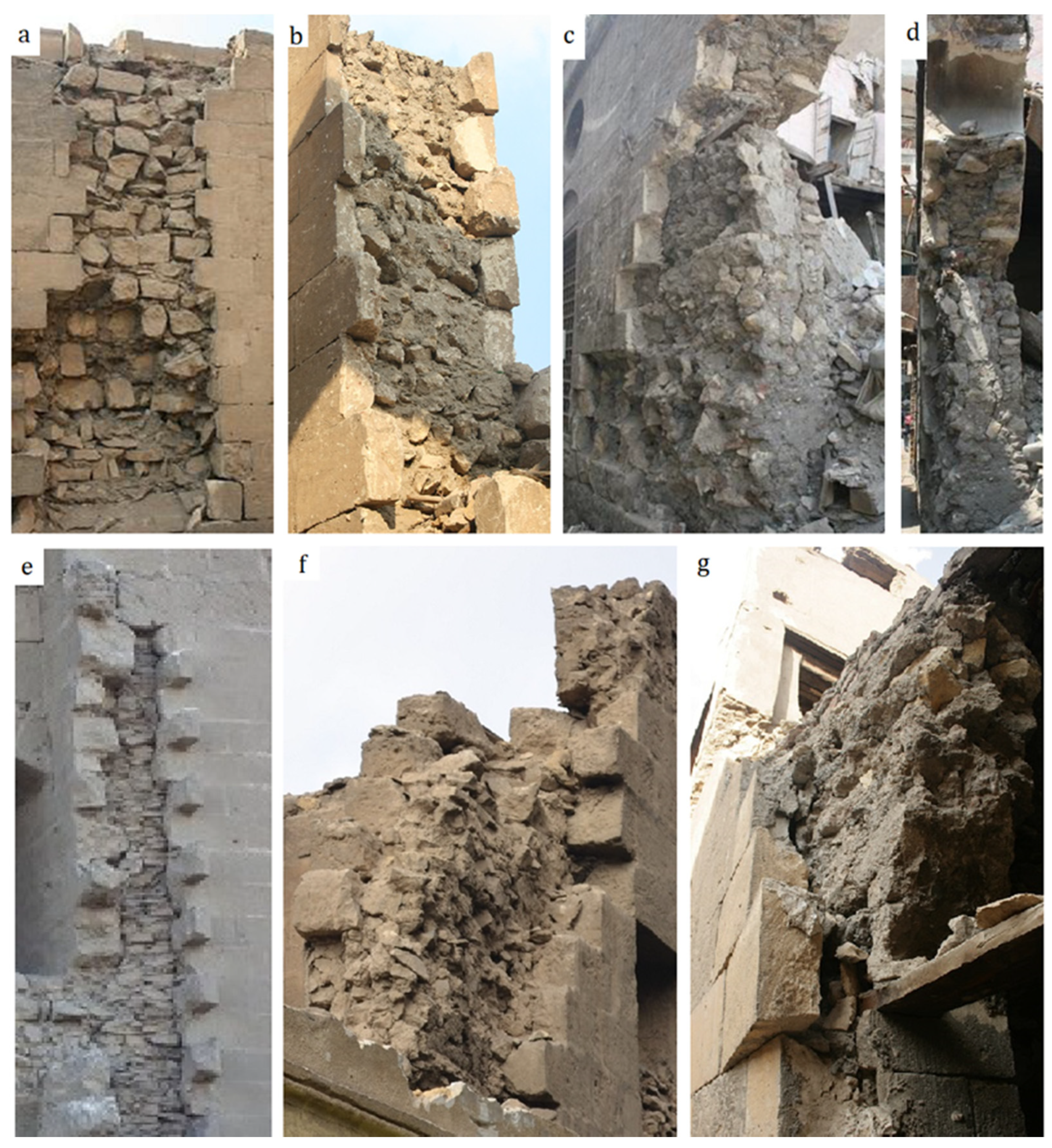
Figure 1. Typical examples of multiple-leaf stone masonry walls: (a,b) Complex of Sultan al-Ashraf Barsbay (835 A.H.–1433 A.D.); (c,d) Zawiya of ‘All al-Maghrabi (1282 A.H.–1866 A.D.); (e) Complex of Al-Sultan Hasan (757–764 A.H.–1356–1362 A.D.); (f) Qasr al-Amir Qawsun (738 A.H.–1337 A.D.); (g) Saray Al-Musafir khana (1193–1203 A.H.–1779–1788 A.D.).
Heritage 04 00135 g001
Figure 2. Tested specimens by means of the hot plate for thermal measurements (a) stone, (b) lime-based mortar, and (c) core-infill samples; (d) heat flow meter apparatus.
Heritage 04 00135 g002
Figure 3. Schematic diagram of the Fox 314 heat flow meter apparatus and plan view of the upper/lower plate showing the guarded area. Adapted from [47].
Heritage 04 00135 g003
Figure 4. Transversal bond elements to enhance the connectivity between wall leaves: (A) external wall of Bab Zuwayla and (B) main façade of Masjid al-Salih Tala’i’.
Heritage 04 00135 g004
Figure 5. Different core-infill materials of multiple-leaf masonry walls: (AC) stone-rubble infill, (D,E) brick-rubble infill, (A,C) Complex of Sultan al-Ashraf Barsbay, (B) Khanqat Khawand Umm Anuk, (D) Sabil Ibrahim Agha Mustahfizan, (E) Saray Al-Musafir khana Zawiya of ‘All al-Maghrabi.
Heritage 04 00135 g005
Figure 6. Various typologies of multiple-leaf stone-masonry walls in historic Islamic buildings: (A,B) slender wall (Complex of Sultan al-Ashraf Barsbay and Bab Qaytbay resbectivly), (C,D) wall of medium thickness (Complex of Sultan al-Ashraf Barsbay), (E) thick wall, (Zawiya of ‘All al-Maghrabi), (F) monolithic/massive wall (Bab Qaytbay).
Heritage 04 00135 g006
Figure 7. Common topologies of the transversal section of multiple-leaf stone-masonry walls in historic mediaeval masonry constructions in Egypt (a) with keyed and (b) straight collar joints.
Heritage 04 00135 g007
Figure 8. Thin section micrographs of (a) limestone samples; (b) mortar samples under cross polarized light (XPL).
Heritage 04 00135 g008aHeritage 04 00135 g008b
Figure 9. X-ray diffraction pattern of representative limestone sample.
Heritage 04 00135 g009
Figure 10. X-ray diffraction pattern of representative mortar sample.
Heritage 04 00135 g010
Figure 11. Thermogravimetric analysis curves of analysed (a) stone and (b) mortar sample.
Heritage 04 00135 g011
Figure 12. SEM photomicrographs and (EDX) microanalysis of thin sections of (a) limestone and (b) mortar samples.
Heritage 04 00135 g012
Figure 13. Stress–strain diagram obtained for limestone specimens with (a) limestone and (b) core-infill specimens.
Heritage 04 00135 g013
Figure 14. Examples of failure patterns for tested (A) limestone, (B) lime-based mortar and (C) core-infill specimens under uniaxial compression.
Heritage 04 00135 g014
Figure 15. Failure mode of (A) limestone, (B) lime-based mortar, (C) core-infill specimens.
Heritage 04 00135 g015
Table 1. Average composition of the minerals for limestone samples.
Sample No.MineralsChemical FormulaSemi-Quant [%]
1CalciteCaCO379
QuartzSiO221
2Calcite, magnesian(Mg0.064 Ca0.936) (CO3)71
GypsumCaSO4 (H2O)223
BariteBaSO46
3Calcite, magnesian(Mg0.064 Ca0.936) (CO3)74
GypsumCaSO4 (H2O)218
QuartzSiO28
4Calcite, magnesian(Mg0.064 Ca0.936) (CO3)100
5Calcite, magnesian(Mg0.064 Ca0.936) (CO3)85
Quartz, low, synSiO25
HaliteNaCl10
6Calcite, magnesian(Mg0.064 Ca0.936) (CO3)77
GypsumCaSO4 (H2O)223
7Calcite, magnesian(Mg0.064 Ca0.936) (CO3)71
GypsumCaSO4 (H2O)218
QuartzSiO211
8CalciteCaCO376
Quartz, low, synSiO215
HaliteNaCl9
Table 2. Average composition of the minerals for the representative mortar samples.
Sample No.MineralsChemical FormulaSemi-Quant [%]
1Calcite, magnesian(Mg0.064 Ca0.936) (CO3)39
QuartzSiO219
Vermiculite-2MMg3Si4O10 (OH)224
Kaolinite-1AAl2Si2O5 (OH)418
2GypsumCaSO4 (H2O)258
CalciteCaCO324
QuartzSiO26
AnhydriteCaSO4.1/2 H2O12
3Calcite, magnesian(Mg0.064 Ca0.936) (CO3)54
Quartz, synSiO219
Albite, calcian, ordered(Ca, Na) Al (Al, Si)3 O823
GypsumCaSO4 (H2O)24
4QuartzSiO292
CalciteCaCO38
5CalciteCaCO39
GypsumCaSO4 (H2O)291
6Calcite, magnesium, syn(Mg0.064 Ca0.936) (CO3)51
Quartz, synSiO238
Hematite, synFe2O311
7HaliteNaCl31
QuartzSiO256
Calcite, magnesian(Mg0.064 Ca0.936) (CO3)13
8DolomiteCaMg (CO3)212
AlbiteNaAlSi3O833
Hollandite (Ti, Mg)Ba6.00 Ti34.00 Mg6.00 O80.0027
CalciteCaCO38
QuartzSiO220
Table 3. Results of DTA-TGA analysis of weight loss (in %) up to 1000 °C for stone and mortar samples.
SampleMass Loss %Total Mass Loss %
Dehydration of Hygroscopic WaterDecomposition of GypsumDehydration of Clay Mineralsα-Quartz
Polymorphic
Inversion
Decomposition of Carbonates
Stone0.227---26.12528.679
0.432---35.29440.329
Mortar2.6970.730-1.2516.40915.127
2.13512.436--4.12525.727
0.247-14.024-1.54017.616
2.5421.834-1.2547.35123.074
Table 4. Average results for the physical tests of limestone, mortar and core-infill specimens.
ρ d   ρ B u l k   WA η Gse
Avg.CVAvg.CVAvg.CVAvg.CVAvg.CVAvg.CV
(g/cm3)%(g/cm3)%%%%%(g/cm3)%%%
Limestone2.0868.952.2588.908.2713.8517.2215.522.52510.8520.9118.47
Lime mortar1.81116.002.06014.7113.9738.0524.9038.872.44418.7334.9948.98
Core-infill1.7152.722.0254.7418.1030.7631.0030.232.52814.9447.4547.34
Table 5. Average results obtained from the compression tests on cubic specimens of 150 × 150 × 150 mm, (values in brackets give the CV).
Tested Specimenfcfc,iεciεpEEtEs
N/mm2N/mm2%%N/mm2N/mm2N/mm2
Limestone22.72 (3.10)6.440.110.416765.1 (7.05)6666.676021.50
Lime-based mortar1.66 (4.02)1.23--1245--
Core-infill4.19 (11.02)0.850.050.242350.47 (16.43)12501142.85
Table 6. Thermal measurement results for the investigated limestone, mortar and core-infill specimens.
SpecimensDensity, ρTemp. Upperλ UpperTemp. Lowerλ LowerPercent DifferenceMean Temp.Avg. Thermal Conductivity, λavg
(kg/m3)°C(W/m K)°C(W/m K)%°C(W/m K)
S12.294420.020.324445.030.33422.9832.5250.3293
S22.276320.020.357245.020.33197.3432.520.3445
M11.649120.010.567145.020.52338.0232.5150.5452
M21.601620.010.575245.020.53088.0232.5150.5535
RM11.852520.020.384545.020.41788.2932.5200.4012
RM21.847720.010.478845.020.44188.0232.5150.4603
Publisher’s Note: MDPI stays neutral with regard to jurisdictional claims in published maps and institutional affiliations.