1. Introduction
The preservation of cultural heritage is particularly relevant in many European countries, such as Italy, where there are 47 UNESCO World Heritage sites (UNESCO). The high vulnerability of monumental masonry constructions was highlighted by seismic events that happened in the last few centuries in the European territory. Among them, those buildings with vaulted roofs represent a large number, and they were prone to sudden failures since they were designed and built to support only gravity loads. The observation of the post-earthquake damages showed that the vaults, domes, clocks towers, bell towers, steep roofs, gables, and apses of the churches exhibited collapses and extensive cracking. Some recent structural failures involving architectural heritage subjected to seismic forces are presented and discussed in [
1,
2,
3,
4]. With particular reference to a vaulted masonry structure, the damage caused by the 2012 Italian earthquake was simulated in [
5]. Nonlinear static and dynamic analyses were carried out using a damage-plasticity constitutive law for masonry. All these studies revealed that the quality of the masonry plays a crucial role, as well as its texture. Under seismic loadings, the vaults often represent a weak link in the structural hierarchy because of their low stiffness in plane. In addition, they may cause out of plane collapses of the walls connected to them when the thrusts are not contained by proper ties or external buttresses. Nowadays, the seismic assessment of existing structures has become one of the most challenging tasks for structural civil engineers. The need to improve the safety levels of existing structures with respect to the actual technical codes, especially under seismic forces, requires complex modeling for ancient vaulted masonry buildings. In this scenario, it is well known that the stiffness of the horizontal elements strongly influences the overall response of the structure [
6]. For this reason, when masonry vaults are present as a floor system, knowledge of their seismic response is mandatory for predicting a reliable distribution of the horizontal forces. With this aim, the evaluation of an equivalent plane element replacing the vaulted floor seems an effective solution, as also presented in [
7], where, for some vault typologies, isotropic or orthotropic membranes were studied as equivalent elements in the global analyses. The evaluation of an equivalent elastic stiffness was proposed to idealize these structural elements. In the present study, an extension of [
7] is proposed by considering a similar approach, which was suggested also in [
8,
9]. In [
7], a correlation is proposed between the axial and shear stiffness of a specific vault type with those of an equivalent plane membrane. The equivalence is an elastic one, since the Young’s modulus in the two principal directions,
EX and
EY; Poisson’s ratio, υ; and the shear modulus, G
X,Y are assumed for comparison. In [
8], the authors simplified the vaults by considering a full-rigid in-plane diaphragm getting a global stiffer behavior. In [
9], the stiffness was considered by analyzing the local modes due to the mass concentrated in the center of mass of the diaphragm. On the other hand, in relation to the assessment and mitigation of seismic risk of the cultural heritage the Italian technical code [
10], takes into account the possible presence of curved floors. In fact, referring to constructions with vaulted floors, it is suggested to adopt an equivalent slab with a suitable stiffness to be determined according to the type of the vault, its geometry, the characteristics of the materials, and the type of connection to the vertical structural elements.
The utility of a such a simplified approach is clear when the mechanical characteristics of the vaults are studied by considering the nonlinear behavior and the geometrical parameters that may affect the equilibrium of the structural system or its sub-parts, as shown in the literature. A recent review study [
11] presented a discussion about the different research approaches, followed by different authors, in studying cross vaults. The authors conclude that numerical methods, compared to experimental studies, can provide the tools for the quantification of the damages produced by external forces applied to cross vaults. A case study on cross-vaults is presented in [
12], showing how to approach the damage assessment of vaulted masonry by using a tridimensional discretization in which the nonlinear behavior is assigned to the interfaces between adjoining elements. A similar task has been studied more recently in [
13], where a new unified computational method is proposed for the structural safety assessment of masonry vaults, able to catch the different geometries and loading conditions. The authors illustrate an analytical validation by comparing the results of the proposed model with those available in the literature. A simplified model has been presented in [
14], where the vaults are considered in forms of equivalent trusses. The equivalent stiffness of the trusses has been calibrated in order to obtain a simplified structural system able to show the same or a closely similar seismic response to the real one. Finite element analyses were used to model the real conditions, to be compared to the proposed simplified scheme. A parametric analysis has been illustrated in order to validate the results of the proposed approach with respect to those of the vaults when fully modeled. A detailed parametric study has been presented in [
15], with the aim of providing exhaustive knowledge of the seismic response of cross vaults by individuating the failure mechanisms in the function of the design parameters. The results of Multiple Linear Regression are provided in order to help researchers and practitioners develop a quick assessment of the seismic capacity of cross masonry vaults.
Very few are those studies studied and modeled an entire structural system considering the real vault’s geometry. A masonry chapel belonging to the German architectural heritage has been studied [
16], considering the real geometry of the ribbed vaults with warped intersections that constitute the ancient roof. The authors underline how special methods of numerical structural analysis are needed to solve this kind of problem, and how difficult the geometrical modeling is in a FEM (Finite Element Modeling) environment when the geometry is not regular. In this case, an Operational Modal Analysis has also been used to experimentally determine the natural frequencies of the building from ambient vibration tests. These data were used to calibrate the FE model using genetic algorithms. The calibrated FE model has been run by performing a non-linear analysis, able to catch the load-bearing capacity of the building.
With “ordinary” ancient constructions—i.e., those used as civil buildings with vaulted roofs—it is not always possible to use sophisticated 3D analyses considering the real geometry of the vaults. This because it would require highly skilled engineers and very powerful workstations able to run solid models with thousands (or millions) of finite elements. In these cases, structural engineers need a solution that would allow them to perform a global analysis without losing much accuracy, and at the same time without unsustainable costs, also in terms of time.
In this paper, the results of an extensive study are presented, with the aim of providing a simplified approach for studying the masonry of vaulted structures, especially under seismic forces. The results will be provided and discussed, considering the precious background provided by the few scientific studies available nowadays, also showing a case study.
It is remarkable to remember that the scope of this study is not the analysis of the collapse of single vaults, since this occurrence is governed by equilibrium considerations based on kinematic limit analysis. The approach proposed herein refers to those vaults without severe damage in the scenario of the global analysis of the entire building.
2. Equivalent Stiffness and Material Properties
In this section, a plate will be identified which is intended to be equivalent to a masonry vault in terms of stiffness, according to the vault’s geometry and the mechanical properties of its materials. The target is to calibrate the equivalent in-plane stiffness as reported in the following. This equivalence would result extremely useful when a global analysis of the existing masonry structures is needed. The equivalent plate elastic moduli are obtained as proposed in [
7] by considering the vaulted floor as a macro element, with appropriate constraints (
Figure 1a,b).
In
Figure 1a, the unstrained side-dimension of the vaults is
2a, and the imposed in-plane displacement is Δ
u, which is assigned in order to evaluate the constraints’ reactions
Ri. With the obvious meanings of the used symbols, the equivalent longitudinal and tangential elastic moduli of the plate are defined by Equations (1) and (2), respectively:
where
2a is the original side-dimension of the vault;
sv is the vault thickness; Δ
u is the imposed displacement, with its components in the
x/y direction;
E is the elastic modulus of the plate (
Ex or
Ey);
σ is the normal stress that is generated in the
x/
y directions, due to Δ
u, and
ε is the corresponding strain;
G is the shear elastic modulus of the plate;
τ is the shear stress induced by the presence of the shear forces;
γ is the corresponding distortion;
F is the resultant of the shear stress applied to the main arches of the vault;
Ev and
Gv are the axial and shear elastic moduli of the vault, respectively.
As it is known, the mechanical response of a specific vault type is related to several parameters, including the geometry, connections to other structural elements (i.e., ties), in-plane dimensions, thickness of the masonry surface, condition of constraints, and overlying filling materials. In this study, the contribution due to the filling materials is disregarded. In this simplification, it may be considered as a simple gravity load. Different types and geometries of vaults and constraint configurations were considered, corresponding to the most common problems in real practice in Mediterranean countries. In all cases, an in-plane square geometry of the vault was assumed, even if this hypothesis does not affect the meaning of the results, and can be easily removed by considering two different dimensions of the vault sides. T barrel vaults and cross vaults were studied, which are commonly found all over Europe and elsewhere. Moreover, two typical masonry vaults, commonly used in Southern Italy (Province of Lecce, Puglia) were also considered and studied. In this last case, many details about the vault geometry are presented in the following section to provide a clear reading of the structural problems and how this kind of vault was derived from the most common vaulted shapes.
The structural analyses were performed using the software ANSYS v.14 [
17]. FEM analyses were carried out considering the vaults as linear elastic systems with the hypothesis of a homogeneous solid. By performing the FEM, the element “solid186” was used from the ANSYS library, which is defined by 20 nodes in its most regular shape (prism with a rectangular base), and through a minimum of 10 nodes in the form suitable for irregular geometries (tetrahedral shape with a triangular base).
Table 1 shows the mechanical properties of the masonry assumed for the analysis.
The material properties used in the analyses of this study were taken considering the real applications in the field of natural limestone masonry. This choice was made in respect of the materials that are used in the typical vaults presented in the following. The values were provided by an extensive experimental campaign that the authors performed on an existing historical building located in the city of Lecce, Italy [
18]. The value of the Young’s modulus was taken according to EC6 [
19], even if respectfully to the experimental outcomes. The value of the elastic modulus in accordance with EC6 was chosen as the necessary value for the numerical analyses; in fact, the analysis is carried out in the elastic range and the equivalent modulus is expressed as a percentage of the initial value. This approach is preferred, since if using a lower elastic modulus value corresponding to cracked elements, the percentage value would be the same.
3. Vault Geometry and Construction Details
The cases of T barrel and cross vaults (also sometimes known as double barrel vaults or groin vaults) will not be discussed herein, since they are well known in the literature. The special vaults typical of the Southern Puglia will be presented due to their unique shape. These vaults can be grouped into two families, even if both of them can be considered as derived from the most common cross vaults. In Southern Italy, and in particular in the Puglia region, complex vaults shapes are widespread, derived from the cross vault. They are commonly referred as “leccesi” vaults. These vaults are typically made according to a rigorous sequence of masonry blocks, which are cut and assembled after the execution of the abutments and walls. The construction of the vault starts with that of the supporting elements (called “hung” and “nails”), thus a specific procedure is followed as described in [
20]. Two types of leccesi vaults are known, which are called “edge vaults” and “square vaults”, as shown in
Figure 2. The edge vaults are also called “star vaults” due to their typical aspect.
Referring to a typical historical building, the structural unit can be considered to be composed by the vault and the vertical bearing elements constraining the vaults, as shown in
Figure 3.
Referring to the simple square roof of side 2a (
Figure 3), which is a typical subsystem of the roofs under study, and to the drawings illustrated in
Figure 4,
Figure 5,
Figure 6 and
Figure 7, the main geometric parameters that characterize the construction form are the height of the poles (H); the distance of the keystone from the source plane (ZO); the portion of barrel vault, (f) (
Figure 4 and
Figure 7); the Z
R1 dimension of the R1 point of the nails (terminal part of the abutments); Z
m (M) dimensions (edge vault) and Z
j dimensions (J and H symmetrical with respect to the diagonal in the square vault); Z
f, which is the distance from the intersection between the nail and the cap to the plant of the source;
2a and
2a′, respectively, are the total size of the vault and the size of the vault at the point where the cap is supported on the hangers, respectively (
Figure 5a); the same meaning is assumed for the dimensions
b and
b′ of the edge vaults (
Figure 5b). The hangers represent the support base of the cap and the nails.
As it can be observed from the pictures in
Figure 5 the edge vault can be seen as derived from a cross vault, where the central portion is obtained by the intersection of a cross vault and an ellipsoid. The square vault is characterized by the angles, which are emptied from the construction material or realized as same as the corners of a quarter of a pavilion vault. In this type of vault, the diagonal axis coincides with that of the diagonal of an equivalent square vault. The result is that the plan of the square vault is an eight-point star, while the plan of the edge vault is a four-point star.
Figure 6 and
Figure 7 show the projection in the horizontal plan and in the vertical plan of an edge vault and a square vault, respectively. These drawings are those used during the construction phases, where the master builders are asked to check the imposed geometry at each stage of the construction process.
The cap of the vault can be considered as a portion of an ellipsoid with the following equation:
where α refers to the measurements on the x axis, β refers to the measurements on the y axis, and γ refers to the measurements on the z axis. The regions of the nails are mathematically described with the same equations of a barrel vault. In particular, in the edge vaults these regions can be considered as the intersection of two-barrel vaults with perpendicular longitudinal directions. The construction geometry of the square vault is known when the positions of the points Q, M, J, H, F, R
1, and R
2, are determined. The same conclusion is valid for the edge vault when the positions of P, M, R
1, and R
2 are set. The different values of α, β, and γ are those corresponding to the positions of these points. In the construction field, the expert master builders set these points by means of a graphical construction made in the field. Thus, the method which is typically followed in the field is an empirical one.
From a more rigorous perspective, assuming a square shape of the plant of the vaults (as it often is in real cases), the values of α, β, and γ follow the equations reported herein.
Case of the square vault:
For common building geometries and for a square plant, zR1 = zR2 = a; xR1 = yR2 = a′·t′ = a·cos(30°)·t′; zM = a/2; zH = zJ = a/2; xH = a′ + h0; yH = a′.
For the 3D modeling of the vault, dimensions were assigned in order to create a numerical model, close to real cases; h0 = 500 mm, τ = 22°, and we use values derived from (4)–(9)
According to the analytical equations, the surfaces of the vaults were defined and represented through the Autodesk Inventor software, as shown in
Figure 8.
With the purpose of performing a parametric analysis, the different types of vault were analyzed by varying the in-plane dimensions (
2a or
2b). Other variables were considered in the parametric analyses: the constraints configuration, the thickness of the side walls (
sp), and the thickness of the vault (
sv). The different constraint configurations are shown in
Figure 9. The positions of the constraints are strongly related to the distributions of horizontal forces in seismic conditions.
Possible constraint conditions are shown in
Figure 9. The different configurations of the constraints in the different positions of the vault strongly influence the distribution of the horizontal forces that are generated under earthquakes.
Figure 9a shows the condition in which the vaults are constrained by supports or in correspondence with the abutment plane, and this corresponds to the lower limit of the distribution capacity of the horizontal actions. With reference to
Figure 1, the vault is supported on one side and a unitary displacement is applied to the opposite side.
Figure 9b represents the case of the maximum distribution capacity of the horizontal actions, in which the stiffness of the structural system increases as the cover is constrained on the plane passing through the kidneys. In
Figure 9c,d, the responses to the shear stress of the roofs are considered in accordance with
Figure 2. Respectively, the constraints are applied on the level to the shutter and to the kidneys.
These different constraint conditions have been applied to the different cases of numerical analysis, as reported in the following.
In total, four different types of vaults have been studied using numerical analysis—namely, cross vault, barrel vault, edge vault, and square vault. Two different dimensions of the vaults’ thickness (cap regions) have been considered: sv = 0.8 mm (thin vaults) and sv = 200 mm (thick vaults). The values that were set by the authors reflect a wide range of real practical applications. For each vault configuration, two different boundary conditions were assumed in terms of the side walls: vaults constrained at their abutments with side walls, and vaults constrained at their abutments without considering the side walls.
4. Equivalent Stiffness Results
In this section, the computation of the equivalent stiffness starts by showing the example of the barrel vaults, since this type of vault does not have symmetry in the two horizontal directions, as found in the other types. In civil buildings, they were typically used as roof for the basement and ground floor, having a span that is typically between 3 and 5 m. In order to evaluate the equivalent elastic tensile modulus, it is necessary to consider the orthotropic behavior of the barrel vault in the two horizontal directions, due to the lack of symmetry. The two terms
(EV/E)L and
(EV/E)T represent the ratio between the equivalent elastic modulus and the original elastic modulus in the longitudinal direction and in the transverse direction, respectively. In the longitudinal direction
L, the ratio
(EV/E)L can be easily considered as
Av/A, which is the ratio between the area of the resistant cross section of the vault and the area of the resistant cross section of the equivalent plate. This last term can be computed as
A = 2R·s according to the dimensions illustrated in
Figure 10, which reports the parameters that characterize the geometry and the cross section of a barrel vault.
By assuming the symbols of
Figure 10, for the barrel vault the following equations can be written in order to compute the area of the cross section and describe the geometry:
According to Equation (9) the ratio of the elastic moduli is written as:
which shows that the ratio of the elastic moduli is independent from the length of the vault, resulting in a constant value equal to π/2 = 1.57. This means that
Ev is 157% respect to the longitudinal elastic modulus
E.
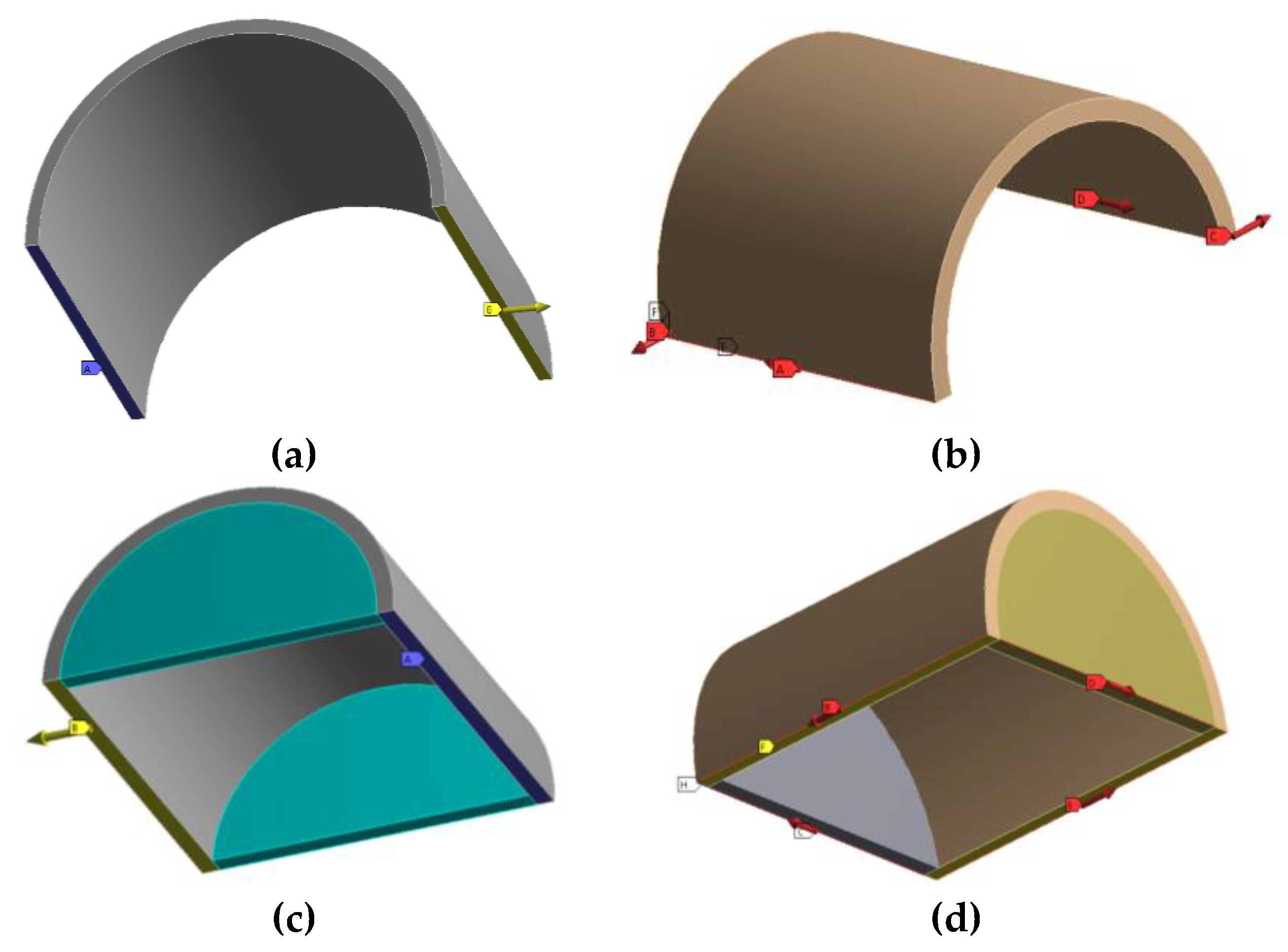
In order to compute the longitudinal stiffness along the transverse direction of the vault, a unitary displacement has been imposed on the free side of the vault by considering the other side constrained by a simple support (
Figure 11a). With the same hypothesis, the tangential stiffness has been computed. In this case, a simple support has been applied on the constrained regions of the vault, considering a self-balanced system of forces applied to the free regions that is able to produce a shear distortion (
Figure 11b).
The same computation has been performed considering the presence of side walls, as shown in
Figure 11c,d. This because, in the case of barrel vaults, the absence of symmetry, due its shape, might be strongly influenced by the presence of transverse elements (side walls) that are able to reduce the displacements. The results shown in the following strongly highlight the role of the transverse wall in increasing the stiffness of the barrel vaults in the transverse direction.
Figure 12 and
Figure 13 show the constraint conditions and applied forces for the square vaults and edge vaults, respectively.
In order to make the reading and analysis of the results simpler, they will be shown by referring to dimensionless geometrical dimensions. A standard side length of 4 m has been chosen as a reference for the dimensionless ratio. With this assumption, the variable arif should be considered as the ratio of the side dimension of the vaults (2a) in meters, and 4 m: arif = 2a/4 [m/m]. The thickness of the side walls, when considered, is indicated as sp, which will be used to represent the variables sp/arif and sp/2a, useful to plot the equivalent stiffness in the presence of side walls with different thicknesses.
In the following subsections, the results will be illustrated and discussed in relationships with the single variable that was considered in the parametric study.
4.1. Influence of the Thickness of the Vaults and Presence of Side Walls on the Stiffness of the Vaults
The presence of side walls is meaningful only for barrel vaults. The results related to this kind of vault show that the presence of side walls is a relevant variable for the transversal stiffness of the vaults, as expected from theory. This is valid for both the global axial and tangential stiffness of the vault. Another important parameter that strongly influences the lateral stiffness of the vault is the thickness of the cap region. As specified above, two different values of the vaults’ thickness (
sv) were tested: 80 mm and 200 mm. The diagrams in
Figure 14 show clearly how the equivalent longitudinal stiffness (
Figure 14a) and tangential stiffness (
Figure 14b) of the vaults decrease with the respective side dimensions (
2a) when varying the thickness of the cap region (
sv). Only the tangential stiffness ratio of the cross vault with the lowest thickness has an increasing trend for side dimensions higher than 4 m. In all the other cases, the trend is a descending one. This may be due to the additional stiffness provided by the membrane effect generated by the shape of the vault.
Figure 15a,b illustrate the diagrams of the vaults’ stiffness in the presence of side walls, considering different thickness values of the side walls. The results are related to those simulations in which the side dimensions of the vaults are
arif = 4 m, by varying the stiffness of the side walls
sp. The stiffening effect provided by the side walls can be easily quantified in terms of the
Ev/E ratio, which is increased with respect to the results of
Figure 14a. The trend appears to be linear or pseudo-linear in all cases. Higher values of the
Gv/G ratio were found in the presence of side walls too, as shown in
Figure 15b, compared to
Figure 14b. In these cases, the trends are not linear and differ for the case of the barrel vaults, which show an inversion of the trend for the case
sv/
arif = 0.020.
All the curves in
Figure 14 and
Figure 15 refer to cases in which the vaults are constrained at the abutments, as is commonly found in real cases. In the following diagrams of
Figure 16, different constraint schemes are also considered in the presence of side walls. The results show that the presence of constraints at the abutments provides a higher stiffness, as expected. A difference of about 20% is found for all the vault types in terms of the longitudinal stiffness. The differences in terms of tangential stiffness are much higher, as illustrated in
Figure 16b. In these cases, differences of up to almost 40% were found for barrel vaults for a side dimension
2a = 4 m (common cases in civil buildings). This means that an investigation in order to verify the real static scheme of the vaults is mandatory when the accuracy of the structural model is a fundamental issue.
The previous diagrams show that the presence of side walls contributes to providing closed-box behaviour, which is the structural response desired by the designers. The presence of a side wall produces more benefits than the constraints at the kidneys in terms of the global vault’s stiffness. In this sense, the capacity to redistribute the horizontal forces for the vaults with side walls and constraints at the abutments appears to be three times that of the same vaults with constraints at the kidneys without side walls (for the case of sv = 200 mm). For example, for edge vaults, the stiffness values, in terms of the capacity of horizontal force redistribution, go from 18.78% with constraint at the kidneys to 41.86% in the presence of side walls for a span 2a = 3 m. The same values go from 13.89% to 30.22% for a span 2a = 5 m, which is more common in real cases. For the edge vaults, these differences are 59% and 32% for the cases of 2a =3 m and 2a =5 m, respectively. For barrel vaults, the differences are 58% and 25% for the cases of 2a = 3 m and 2a =5 m, respectively.
In all cases, as expected, the stiffness ratio of the vaults decreases with an increase in the span (2a). Only for the cases of the tangential stiffness of the square vaults, bounded at the abutments in the presence of side walls, there is a knee point (2a = 4.2 m). In this case, the tangential stiffness seems to slightly increase after the knee point.
4.2. Comparison of the Structural Response in Absence of Side Walls
In this section, the results will be presented in terms of the longitudinal and tangential stiffness for those cases in which the thickness of the vault cap is 200 mm (more common than thin vaults); the vaults are constrained at the abutments, as is common in real cases; the vaults are constrained at the kidneys; side walls are not present. In
Figure 17a,b, the stiffness ratios are plotted with reference to the side dimensions of the vaults.
From the plots, it is evident that the same decreasing trend is found as the span 2a increases, as expected. The behaviour of the edge and cross vaults seems to be overlapped for those cases in which the span is equal to or higher than 4.0 m. This was found for both the axial and tangential stiffness ratios.
5. Mechanical Response of Vaults and Equivalent Plate Systems
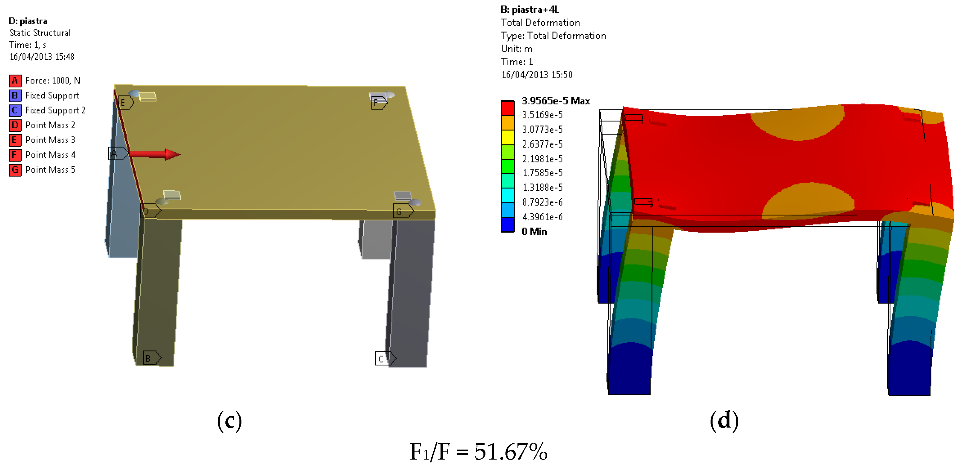
In this section, the results of the FEM analyses will be shown, comparing the vaults modeled with their geometry, with equivalent plate systems in which the reduced moduli were computed according to Equations (1) and (2). The structural scheme used for the computation of the seismic response was conceived as a structural roof supported by four columns, as shown in the cross section of
Figure 18.
For the computation of the excited mass, the filling materials that are placed around the cap of the vault were considered with a density of 10 kN/m
3. The columns were considered with a square cross section. For those cases in which the vault has been modelled as an equivalent plate, all the loads where considered as nodal forces at the top of the columns. In the first stage, the vaults were loaded with a distributed load f
i, as shown in
Figure 18, with a resultant value of 1 kN. The reaction at the base of the columns is called F
1 with reference to the applied F = Σ f
i.
The side of the square cross section of the column is represented by B, while the height of the columns is indicated by H. In the numerical simulations, the range of B was contained between 0.3 and 2 m, while H varied from 1.8 to 4.00 m. The span of the vault will be indicated as arif, which corresponds to the side 2a in the previous sections. The capacity of the lateral force redistribution of the structural roof (vault/plate) has been evaluated in terms of the F1/F ratio, which is correlated to the ratios (B/arif) and (H/arif). The numerical results were also obtained for the limit cases F1/F = 0.5, which means stiff plate, and F1/F = 1.0, which means that the plate has zero stiffness. The parametric analyses were performed by varying the dimensions of the columns (B and H), assuming span values are in accordance with those cases of real engineering practice.
In
Figure 19, the results of the numerical analyses are shown for the edge vault with side walls, where
sv = 0.2 m, and the equivalent plate, obtained using Equations (1) and (2). In
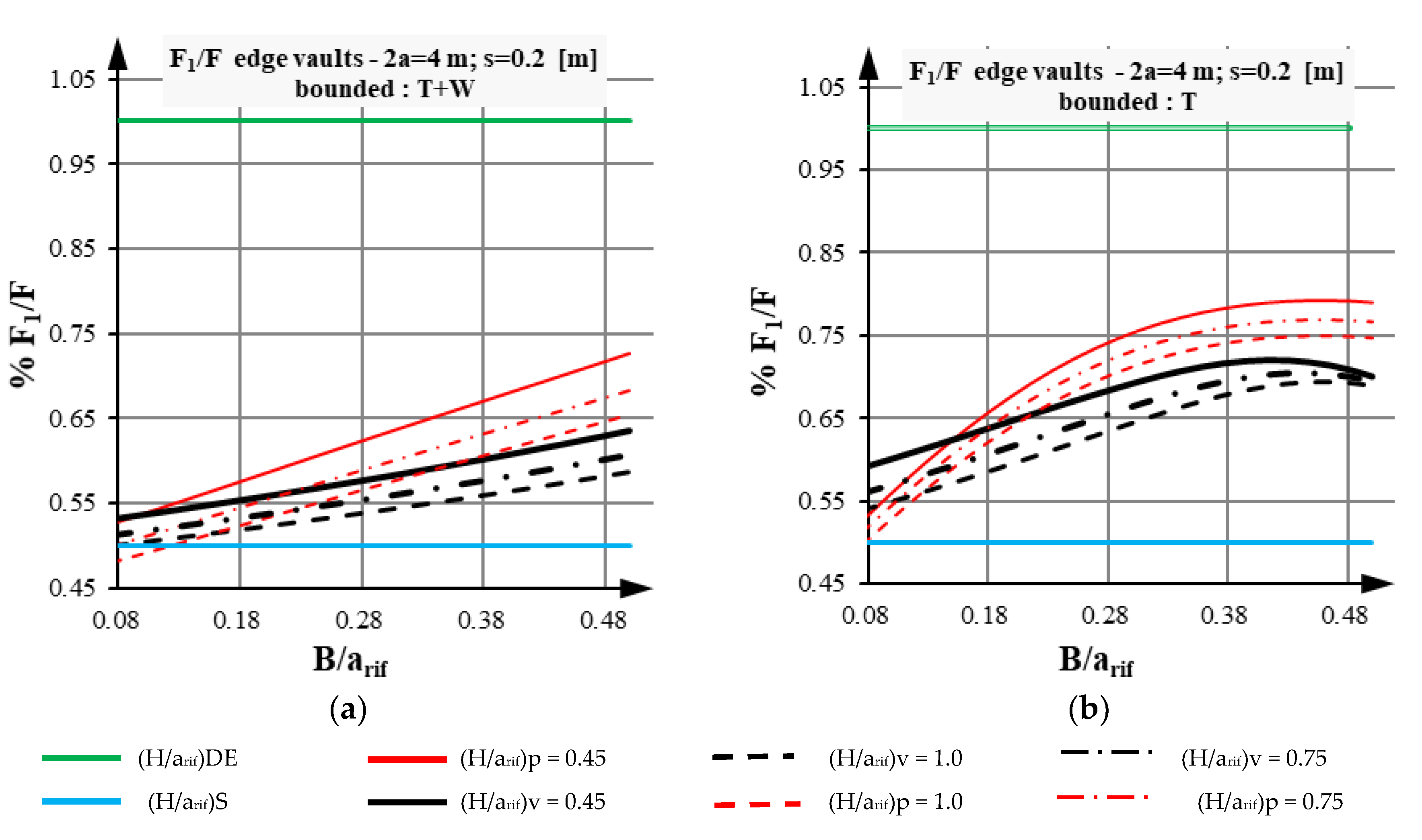
Figure 20, the force redistribution ratio (
F1/F) is plotted with reference to the dimensionless geometrical ratio (
B/arif). The label
v refers to the case of the numerical simulations of vaults; the label
p refers to cases of the numerical simulations of equivalent plates; the label
DE refers to the case of deformable plates (zero stiffness); the label
S indicates the cases of stiff plate.
Figure 20a refers to the case of the absence of side walls, while
Figure 20b refers to the presence of side walls. In both cases, the solution with equivalent plate falls in the range between the limit cases of infinitely stiff and deformable plates. This confirms that the equivalent plate provides a realistic solution in terms of the lateral force redistribution.
The condition of H/arif = 0.45 (corresponding to a high stiffness of the columns with respect to the stiffness of the roof), as expected, shows that F1 prevails with respect to the forces transmitted by the roof to the columns placed on the opposite side. This trend is more evident when the values of the B/arif ratio increase (stiff columns). The presence of the side walls has an important role in the distribution of the lateral force F. The fraction of the whole horizontal action between the piers becomes more efficient, with differences of up to 10%. Similar results (not all shown in the present work) can be deduced for the cross, barrel, and square vaults; in the case of the barrel vault, the influence of the side walls has a higher incidence (about 29%).
6. Dynamic Behavior of Edge Vaults and Equivalent Plate Systems
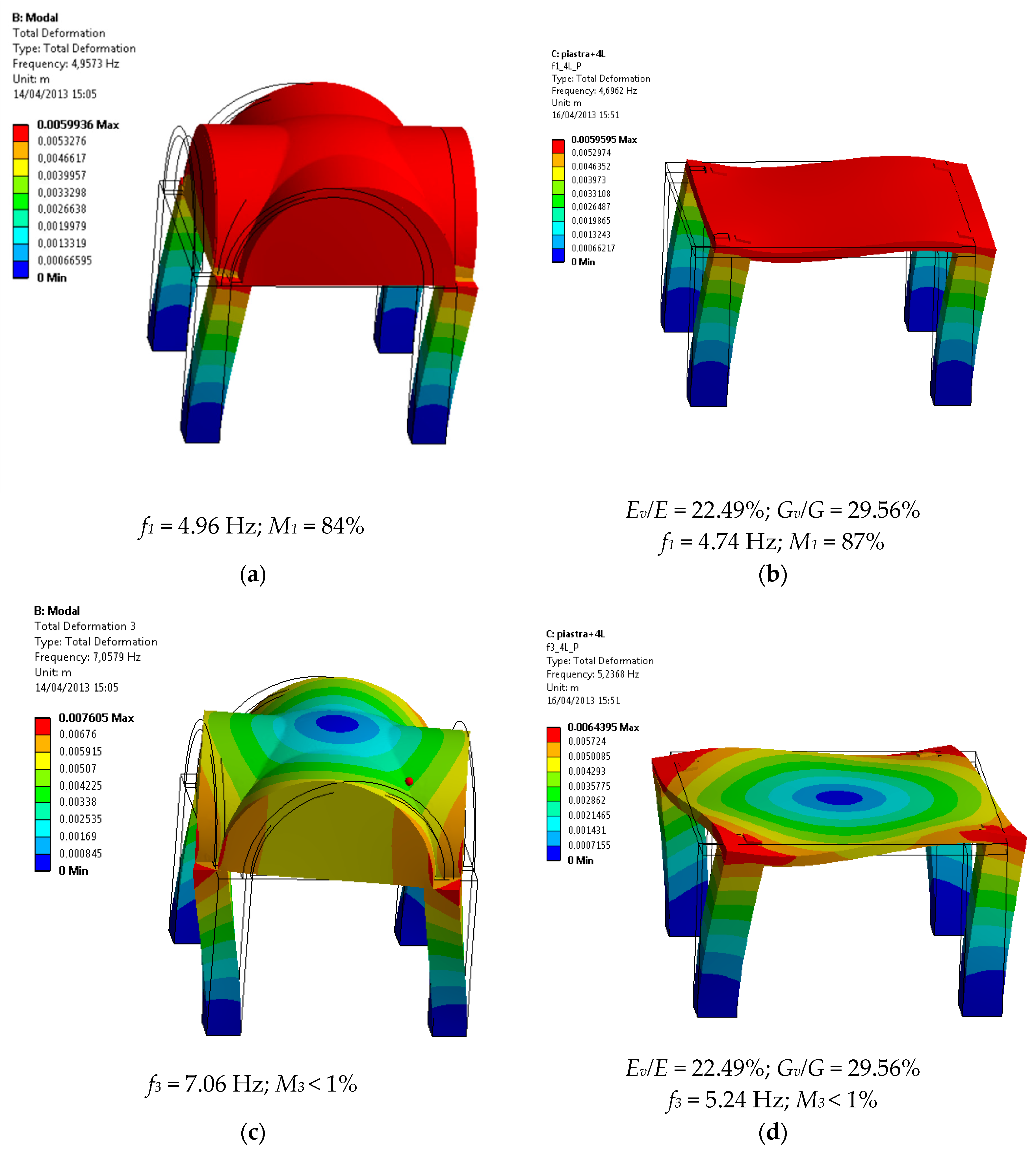
A linear dynamic analysis (modal) has been implemented in the FEM code. The modal shapes and vibrational frequencies of the vaults and equivalent plates were studied and compared in order to verify how the mechanical equivalence is related to a similar dynamic response. The same solid models used for the static analyses previously described were used for the modal analyses. The study for the edge vault is presented herein. In
Figure 21a, typical edge vaults, commonly found in real applications, are shown and compared to the equivalent plate system. The span between the columns is 4 m; the square cross section of the columns has dimensions of 700 × 700 mm; the height of the columns is 3.5 m. The thickness of the vault cap is 200 mm, with side walls that are present in all sides of the vault. The total mass of the vaulted structure was computed to be equal to 225 kN (22.5 ton); the mass of the side walls was computed to be equal to 100.8 kN (10.08 ton); the total mass of the filling at the extrados was computed to be equal to 100 kN (10 ton). The first modal shape is related to the translational vibration along one of the principal axes of the structure. Due to the symmetry of the structural system, the first and second modal shapes involve the same mass and the same frequencies. The third modal shape is related to rotational vibration, which describes a torsional behaviour of the system. The first (and the second, as also intended in the following) modal shape of the vault in the
x (
y)-direction involves 84% of the mass as excited in the first mode. The frequency is 4.96 Hz. For the equivalent plate system, in the same first (second) modal shape, the excited mass is 87%, while the vibrational frequency is 4.74 Hz. The rotational modal shape of the vaulted structure involves a negligible amount of mass (1%), with a frequency of 5.25 Hz. The rotational shape of the equivalent plate system involves 1% of the mass, with a frequency of 7.06 Hz. The results of the numerical simulations are summarized in
Figure 21.
In the absence of side walls, the same simulations were run. The vibrating mass of the first (second) modal shape was 84% and 78% of the total mass for the vaulted structure and for the equivalent plate, respectively. The third rotational modal shape involves less than 1% of the total mass.
A parametric modal analysis was run considering the ratios
and
. The same case listed above for the edge vault with s
v = 200 mm is shown herein, constrained at the abutments with side walls. The equivalent plate system was compared considering the same parameters. The results are illustrated in the form of diagrams in
Figure 22. The curves refer to the vaulted system (v) and the equivalent plate (p); in all cases, they show an ascending branch in terms of the 1st vibrational frequency versus the increase in the
ratio. For high values of the
ratio, the frequency shows a peak. This means that, in those cases after the peak, the columns are very stiff and act as a rigid constraint for the roof. After the peak, the vibrational effect is related locally only to the roof system, without involving the support columns.
The difference between the results obtained for the vault and the equivalent plate models, in terms of the vibrational frequency and the modal behavior of the structure, is shown in
Table 2 for the case of constraints at the abutments and in the presence of side walls, and in the
Table 3 for the case of constraints at the abutments and in the presence of side walls. When the constraints are at the kidneys, the stiffer behavior of the vault reduces the possibility of local modal deformations.
7. Case Study
An entire ancient building was studied and analyzed by applying the criteria of equivalent stiffness, as described before. The masonry building was built in the 16th century in Southern Italy in a low seismic area; the Italian technical code provides for a ground acceleration peak of (PGA) a
g = 0.05 g for the site. This value is used for the seismic analysis of the building. The building has two floors in addition to an underground floor, which was entirely excavated in the rock. The building is irregular in terms of its mass distribution and stiffness in both the horizontal and vertical directions. Natural materials were used to build the walls (limestone blocks); at the ground floor, all the roofs are made of vaulted structures. In
Figure 23, an external view of the building is shown.
The vaults at the ground floor are barrel vaults. The original roof at the first floor was made of wood and iron, but it was demolished after fire events a long time ago. Then, the roof was made of reinforced concrete slabs with T-beams. At the moment, after a global restoration of the building which finished in 2018, the roof is made of glulam timber with a reinforced concrete stiffening plate at the extrados. At the ground floor, the walls are made of single leaf wall (200 mm thickness) or double leaf wall (300 mm thickness), with limestone blocks that were produced by the quarry that was close to the building. In the case of double leaf walls, an inner non-structural thickness of 100 mm was found, made of non-structural building materials such as irregular stones and bricks mixed with earth. This was made by ancient handcrafts to increase the stiffness of the walls and to provide better thermal properties. In some cases, (ground floor) the single leaf walls were coupled with an external wall made of irregular stones without any structural properties. The volume placed underground was excavated from the rock, with a roof made of a thick rock plate.
The structural model performed within the SAP 2000 code, which reproduces the entire building, is illustrated in
Figure 24.
The material properties were extensively studied by performing experimental tests from samples that were available on site. More than 500 compression tests were conducted in accordance with UNI EN 1926:2007 on stone cubes with the dimensions 70 × 70 × 70 mm3. The average density of the stone was 1508 kg/m3 and the average compression strength was 8.86 MPa, with a standard deviation of 2.58 MPa. The elastic modulus of the stone was 3820 MPa.
In the case of double leaf walls with an inner non-structural core, the structural elements were taken as homogenized. In this process, only the structural parts were considered, with the elastic moduli
E1 and
E2, while the modulus of the inner core was considered as
E3 = 0. The homogenized modulus was computed as:
where:
Ei = elastic modulus of the i wall leaf;
si = thickness of the i wall leaf;
1 and 2 refer to the structural leaves;
3 refers to the internal non-structural core.
Figure 25 and
Figure 26 show the plan of the buildings at the different floors, as obtained from an exhaustive structural survey made by the authors. The values of the elastic modulus used in the numerical simulations are reported close to each wall.
The foundations of the building are placed upon bed rock, made of the same limestone that was used for the original construction.
From a global perspective, the vertical elements of the building were modelled as an equivalent frame structural system, in which the columns are continuous elements that form the foundations to the top. The horizontal regions that connect the vertical elements were modelled as beam elements which are connected to the vertical elements through stiff nodes, with dimensions that are related to the dimensions of the horizontal region and of the vertical element that generates the node. The underground region has been considered as a rigid constraint for the remaining part of the building.
As regards the structural roof and their mass distributions, the following considerations are valid. Due to the deformability of the vaulted structures (barrel vaults) and the impossibility of defining a stiff plate with a unique master-= node in which the total mass is considered [
8], the seismic masses were distributed according to the influence areas. For the model that was run with the equivalent plate configuration, the same approach was followed.
In the numerical model with vaulted structures, these are connected to the structural frame through rigid links that are placed at the quote of the kidneys, connecting all the frames, as seen in
Figure 27a.
Figure 27b shows the structural model obtained by computing the equivalent plates.
The modal analysis has confirmed the strong irregularity of the buildings in terms of the geometry and stiffness distribution. A total of 94.8% of the mass was excited only at the 40th modal vibration in the
x-direction (long side). A total of 90.8% of the mass was excited only at the 40th modal vibration in the
y-direction (short side). The first modal shape (
Figure 28a), with a period T
1 = 0.311 s, is related to the direction perpendicular to the barrel vaults; in this case, 66.3% of the total mass is excited.
Figure 28b is related to the second modal shape along the
Y axis, parallel to the vaults, involving 32.4% of the total mass. In this case, the period T
2 = 0.236 s. The third modal shape, with a period of T
3 = 0.217 s, is also a translational mode along the
Y axis, involving 36.4% of the total mass. The first three modes represent the global behavior of the building. The cumulative mass involved in the
X-direction and the
Y-direction is equal to 69.12% and 67.85%, respectively. The values of the excited mass in correspondence with the 4th mode and the following is very low, since they represent the local vibrations of some parts of the building. The modal analysis has confirmed the strong irregularity of the buildings in terms of the geometry and stiffness distribution.
For the structural model implemented with equivalent plates in place of the vaulted structures, at the ground floor the equivalent elastic properties were obtained for the plates according to Equations (1) and (2) in the longitudinal direction (L) and the transverse direction (T), with respect to the axis of the barrel vaults. The following values were obtained and used in the numerical simulations: (Ev/E)L = 5997.4%; (Ev/E)T = 118.8%; (Gv/G)L = 23.7%.
The first modal shape (
Figure 29a) of the equivalent model, with a period T
1 = 0.302 s, is related to the direction perpendicular to the barrel vaults; in this case, 65.8% of the total mass is excited. In this case, the error computed with respect to the vaulted model was negligible: it was 3% in terms of the period and 1% in terms of the excited mass.
Figure 29b is related to the second modal shape for the equivalent model along the
Y axis, parallel to the vaults, involving 47.9% of the total mass, with a period T
2 = 0.244 s. In this case, the error in terms of period was 4%, while for the mass it was 16%. Even if the error range was higher, the result can be considered more than acceptable for the purpose of global analysis. The third modal shape had a period T
3 = 0.219 s; it is also a translational mode along the
Y axis, involving 19.0% of the total mass. In this case, the maximum error was in terms of the excited mass, equal to 17%, while it was negligible in terms of the period. Additionally, in the case of equivalent structure, the values of the excited mass in correspondence with the 4th mode and the following is very low, since they represent the local vibrations of some parts of the building. In correspondence with the 40th modal shape, 95.0% of the total mass is involved in the
X-direction (94.8% for the vaulted structure), and 93.2% of the total mass is involved in the
Y-direction (90.8% for the vaulted structure).
Due to the geometrical irregularities, the seismic input along the two main directions, X and Y, generates a torque of the structure, which causes flexural moments in the direction orthogonal to the seismic force. Thus, with a seismic input along the X-axis, a flexural moment M2 is computed in the plane perpendicular to the seismic input, and a flexural moment M3 is computed in the plane of the seismic input. The same conclusions are made for the shear forces V2 and V3, with the meaning of the subscripts 2 and 3. Along the direction Y, the flexural moment and shear forces are computed too. In this case, the subscripts 2 and 3 assume a commuted meaning.
Figure 30 reports an example that illustrates a partial structural system of the building in order to show a comparison between the results of the numerical analyses for the vaulted and equivalent structure. This structural system was chosen, since it presented worse situations in terms of the error between the solutions of the vaulted model and that of the equivalent model. This representation allows us to easily commence the comparison considering the results reported in
Table 4, where the internal forces values (moment and shear) can be analyzed.
In
Table 4, the results of the vaulted models are reported in terms of the flexural moments and shear forces, with the error in %, with respect to the equivalent model solved with plates.
The direction of the seismic input is intended in the positive direction and reversed by 180°. It is remarkable that, in the X-direction, the errors (% ratio between the results of the solid model respect to the plate model) are less than those in the Y-direction. This is due to the different impact the structural irregularities have in the two orthogonal directions. Along the Y-axis, there are some elements (beam 124 and 142) where the difference in the internal forces is significant.
8. Conclusions
In the present work, the structural response of vaulted roofs was compared to the response of equivalent-plate structural systems. The equivalence between the vaults and the plates was assumed by considering the elastic stiffness of the respective elements along the two principal directions. Different types of vaults were considered, including special-type vaults, which are commonly used in the south-eastern regions of Italy. The simplified model proposed herein allows us to replace the vaulted roof with an equivalent plate of the same thickness and the same dimensions, but characterized by reduced elastic moduli Ex, Ey, and Gxy, which take into account the shape effect of the vault. Using finite element analysis (FEM) conducted with the help of ANSYS software v.14, it was possible to evaluate the influence of the geometrical and mechanical parameters on the equivalent stiffness of the plate. The equivalent elastic moduli are expressed as a fraction of the modulus of the original material; the in-plane dimensions of the vaults varied from 3 to 5 m, the thicknesses of the vault were considered to be equal to 80 and 200 mm; different constraint conditions were also studied. On the basis of the obtained results, it appears that in all cases the typical leccesi vault, called a square vault, is the stiffest one; the behavior of the edge leccesi vault is similar to that of the cross vault. The constraint configuration significantly affects the in-plane stiffness; in particular, the highest stiffness values are obtained in the presence of side walls, often found in practical situations.
The modal analyses run for the vaults and the equivalent plated systems revealed that the equivalence in terms of the excited mass and vibrational period is respected also for the dynamic properties.
An entire building was studied and modelled in order to apply the proposed procedure, considering a real case of a heritage building with a high level of structural irregularity. In this particular case, the barrel vaults were replaced with equivalent plates. The results have shown that, in terms of the global response, the properties of both models were similar, without significant errors.
The computation of the internal forces was accurate in most of the cases, even if unacceptable levels of error were found for two structural elements. In fact, for the first three modes, the vibration periods of the real system and of the simplified model evidenced differences of up to 4%; the differences in terms of the participant mass were equal to or less than 16%. The maps of the principal stresses, under seismic forces, show errors between the plate model and the vaulted model that are less than 10% for most of the elements. Only for some elements did the error reach 50%.
Further research is needed in order to verify the accuracy of the plate-based model in place of vaulted complex 3D models. Further studies should compare the responses of the buildings modelled with real geometry and with a simplified strategy, considering non-linear static analysis. Different type of vaults should be investigated, assuming accurate constraint conditions, in order to compare the global response of the different numerical models.


