


Abstract
This study presents a passive mechanical filter designed to enhance sub-Hertz Venusquake detection by shaping the seismic transfer path. The mechanism uses a tunable, high-Q pendulum mounted inside a cylindrical enclosure on a three-ring gimbal to ensure self-leveling and alignment in gravity on uneven terrain. Unlike approaches that rely on broadband digitization and require active control and a stable power supply, this housing–gimbal mechanism performs mechanical filtering for sub-Hz signal amplification and higher frequency attenuation without power. Response spectrum analysis shows that the transmissibility can be tuned to achieve peak sensitivities in the 0.5–0.8 Hz range. When tuned to 50–55 mm pendulum length and under assumed undamping, the pendulum-mounted mechanism improves detectability at best by 10–100× relative to a bare sensor for moderate magnitude ( = 3–6) in a 12 h observation window, with signal-to-noise (SNR) ratio of 3, and amplitude spectrum density (ASD) of 10−8 m/s2/√Hz. Furthermore, we extrapolate that the predicted minimum detectable event rates follow , where is the quake wave frequency. The damping ratio, considering both structural damping and viscous drag, is estimated to be in the order of 10−3 to 10−2. A probabilistic sensitivity analysis is performed to account for the inherent uncertainty in the spectral mismatch between the narrowband sub-Hz resonance of the designed mechanical filter and the peak frequencies of seismic events; the derived probability model suggests strategies for improving the detection probability in the 0.01–1 Hz range.
1. Introduction
Venus holds a key to understanding the divergent evolutionary paths of rocky planets in our Solar system. Despite its similarity in size and bulk composition to Earth, Venus’s surface environment is extremely hostile, affecting survivability and the performance of conventional lander instrumentation [1]. Unlike Earth, which is characterized by active plate tectonics and a benign surface environment, Venus exhibits a stagnant-lid geodynamic regime where seismic events are less frequent but can serve as a probe to the planet’s internal structure [2]. Despite growing evidence of ongoing volcanic activity, direct seismic observations remain limited, leaving Venus’s internal structure puzzling in terms of seismicity [3]. While the occurrence of surface quakes on Venus was theoretically estimated as frequent as a few millihertz (mHz) based on the atmospheric-solid body coupling model [4], it could fall within the range of 0.01–0.1 Hz based on ground sensing [1]. In either scenario, achieving sensitive, long-duration seismic measurements on Venus requires specialized engineering solutions tailored to its extreme environment and unique geodynamic regime, and terrain topology. Seismological observation of Venus differs from the terrestrial methods due to extreme surface conditions (T ≈ 460 °C, P ≈ 90 bar) that prohibit traditional long-duration ground-based stations. While Earth seismology uses global networks of surface-coupled broadband sensors with stable power infrastructure, Venus seismology techniques rely on atmospheric seismo-acoustics and orbital interferometry, with emerging ground-based detection [5]. The current rigor in this field aims to evaluate different seismic observation techniques on the Venus surface, to identify optimal detection methods and target regions [6]. A comparative summary of detection methodologies is provided in Table 1.
Table 1.
Comparative summary of detection methodologies: Earth vs. Venus.
While the balloon-borne infrasound sensors and orbital airglow imaging (still in evaluation) offer valuable alternative pathways to seismic detection, the seismic-to-atmospheric coupling inherently limits their detection of seismic waves below 1 Hz [13]. They also require calibration to reliably differentiate seismic signals from environmental and electronic noise [5].
Ground-deployed sensors, although technically challenged by the planet’s harsh surface conditions, remain the most direct and informative in preserving waveform fidelity, providing full frequency bandwidth, and capturing low-magnitude events [14]. This can be evident by Mars InSight’s seismic experiment (SEIS), which detected over 1300 marsquakes in the sub-Hertz and 1–3 Hz ranges [15]. It suggests that, when properly coupled to the ground and shielded from wind, the ground-deployed seismometers can effectively monitor quakes [16]. The extreme surface environment on Venus, however, will limit the operational lifetime of ground-deployed seismometers. Historically, the longest a seismometer has survived on Venus was approximately 127 min, achieved by the Groza-2 seismometer aboard the Soviet Venera-13 lander [17]. Despite its longer duration, Venera-13’s seismometer did not detect any microseismic activity. Venera-14, with a shorter lifespan of just 57 min, recorded two potential microseismic events after ruling out the system and wind noises [17].
Seismometer designs for long durations on the Venus surface have been explored in concepts in LLISSE [18] and SAEVe [1]. Specifically, SAEVe’s mission planning emphasizes balancing limited operational time with reliable seismic detection. It employs a ground-deployed MEMS 3-axis sensor, as opposed to the uniaxial ‘Groza 2’ instruments on Venera-13 and -14 landers. In SAEVe’s concept, the sensor’s vertical axis remains continuously powered for “listening,” consuming up to 66% of the energy budget, while full 3-axis sensing is triggered only by significant seismic events. The trigger threshold for such active detection to avoid both excessive and insufficient detections for conserving power without missing critical events is still under deliberation. However, continuous listening is vulnerable to ambient and system noise, leading to wasteful energy expenditure.
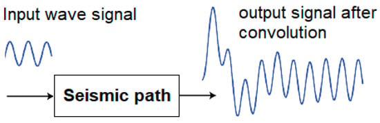
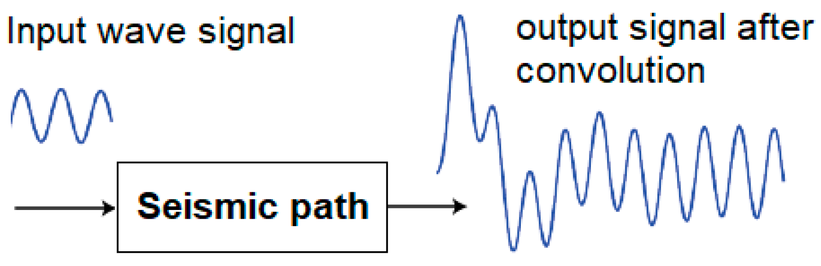
A second challenge involves the degradation of waveform fidelity due to ground coupling, defined as the interaction between the seismic motion and the propagation path from the source to the instrument [19]. As seismic waves travel through this path, which includes the soil, housing, and frequently the lander structure, they are distorted by these coupling interfaces, as illustrated in Figure 1 and detailed in the Supplementary Materials, and as also complemented by studies in the literature discussing how such coupling is widely recognized as not robust and difficult to control.
Figure 1.
Ground/mechanical coupling. An output signal is a convolution of the input signal and the vibrational characteristics of the media, which includes the ground and the mechanical coupling, in the seismic path.
Ground coupling can be modeled as a convolution integral in the time domain [20] or as a transfer function between ground motion (input) and the seismic signal (output) [21,22]. Any structural resonances within the seismometer’s passband will amplify this distorted signal, potentially leading to false triggers. Factors such as material deformability, surface roughness, and the lander’s deployment orientation further influence ground coupling. A stiffer seismic path, characterized by broader spectral bandwidth and resonances outside the seismometer’s bandpass, better preserves the integrity of the seismic signal. Ensuring that seismometers are “reasonably well coupled to the ground” is thus crucial for reliable seismic detection [14]. On-deck seismometers tend to exhibit a broad, complex spectral response due to heterogeneous lander structures [22], whereas directly ground-deployed sensors have simpler transfer characteristics but are still influenced by soil properties, material compliance, surface roughness, and deployment orientation. Wind loading and lander vibrations can inject low-frequency mechanical noise, masking the weak sub-Hz seismic signals of interest. Even small deviations in transfer function have been shown to cause measurable detection errors [23].
Design robustness to modeling errors and disturbances imposes another concern for lander-deployed seismometers. The coupled lander–ground–instrument dynamics strongly shape the instrument transfer function and achievable spectral sensitivity [19]. Small deviations in a seismometer’s transfer function have been shown to introduce measurable errors [23]. Moreover, models and field tests showed that wind loading and lander structural vibrations inject low-frequency mechanical noise into the ground that can mask seismic signals of interest [21].
These cumulative issues open a new avenue for developing robust passive filtering mechanisms for Venus seismic detection. Such filters can differentiate authentic seismic events from a noisy background and conserve limited power resources by preventing unnecessary event recording. Analysis of Venera-14 data [17] illustrates that, without effective real-time filtering, raw seismic streams are dominated by noise, requiring extensive post-processing to isolate signals of interest. An optimal framework should therefore enhance sensitivity in the sub-Hz range while attenuating higher-frequency disturbances, regardless of deployment configuration or landing conditions.
No Venus seismic experiment to date has employed a dedicated passive mechanism to modulate and control the spectral response of the seismic path. We demonstrate such a mechanism, which is a robust, low-pass mechanical filter placed between the ground and the seismometer, to selectively amplify sub-Hz seismic signals while attenuating higher-frequency responses such as wind-induced vibrations.
This approach directly imparts the desired high Q-factor in the sub-Hz range without the impractical task of tuning the entire lander–seismometer assembly, whose wide-band spectral characteristics arise from complex module geometries, diverse materials, and unpredictable landing conditions (as argued in Section 2.1). When tuned appropriately, the seismic path itself becomes a robust passive low-pass filter, amplifying desired signals, attenuating unwanted noise, and reducing false detections. Building on this principle, Section 2.2 introduces the design and implementation of our novel mechanism, and the subsequent sections present a comprehensive evaluation of its effectiveness and robustness. The results of the designs are numerically compared and discussed in Section 3. Section 4 (Discussion) further reconciles this approach with the theoretical broadband strategies commonly used in terrestrial seismology, clarifying why those traditional methods, while valid on Earth, are not feasible on Venus and how the present passive design addresses these constraints. Additional results and analyses are provided in the Supplementary Materials.
2. Methods
2.1. Motivation and Conceptual Framework
Characterizing the seismic path of a lander–seismometer system on Venus is inherently complex. Even when an explicit transfer function can be formulated, the resulting dynamics are highly system-specific and sensitive to modeling approximations, ground coupling, and sensor mounting conditions [19]. This sensitivity persists even in analytically solvable models, such as simple spring-attached inverted pendulums [24], highlighting the fundamental difficulty of deterministic seismic-path characterization.
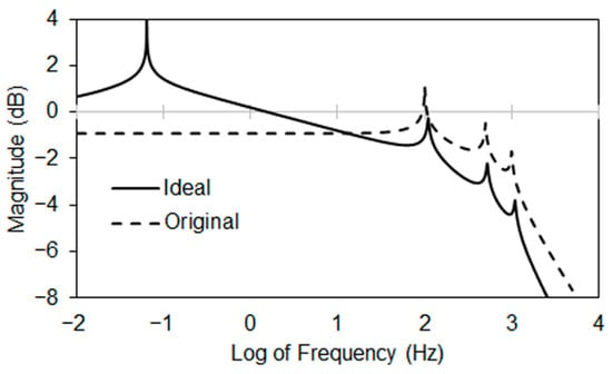
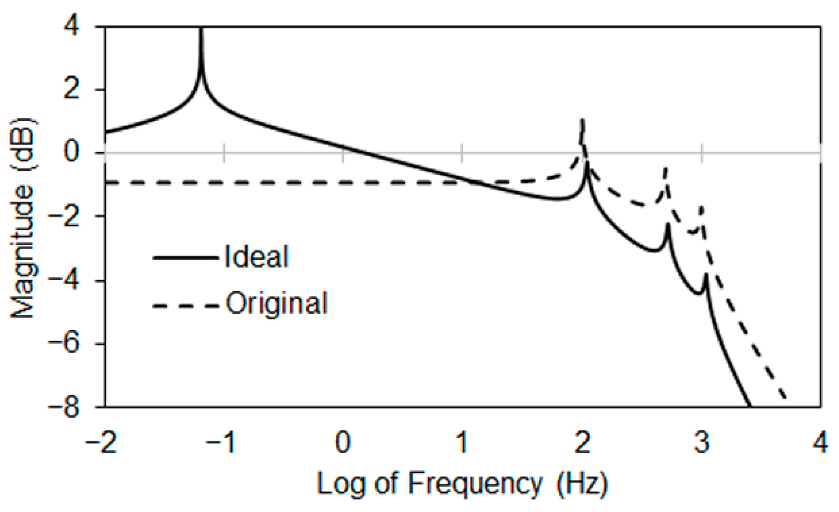
These limitations motivate a shift in methodology from precise lander-associated modeling to the definition of an ideal seismic-path behavior that is intrinsically robust to lander complexity, unpredictable landing conditions, and environmental disturbances. For detecting weak sub-Hertz seismic signals, such a path would exhibit a high Q-factor within the target frequency range, selectively amplifying faint ground motion while attenuating higher-frequency response associated with wind and structural noises. Figure 2 illustrates this target spectral behavior: contrasting a narrowband, high-Q sub-Hertz amplification (“Ideal”) with the broadband response of an unmodified system (“Original”).
Figure 2.
Schematics of an ideal transfer function for an integrated lander-seismometer system. A high-Q response in the sub-Hertz band selectively amplifies weak seismic signals, while higher-frequency noise presented in the original system response is attenuated.
Achieving this ideally depicted spectral shaping by directly tuning lander’s seismic path is impractical, due to the lander’s heterogeneous structure and the unpredictability of landing conditions. Although a generalized transfer-function formulation is available in the Supplementary Materials (Equations (S1)–(S4)), its complexity highlights the limited feasibility of lander-level modeling.
To address these challenges, we introduce a robust, passive mechanical mechanism bridging between the ground and the seismometer to impose the desired spectral response. Acting as a mechanical filter, this mechanism enhances sub-Hz sensitivity by increasing the system’s Q-factor while suppressing high-frequency noise, without explicitly addressing the lander-specific dynamics. The following section presents a pendulum-based implementation of this concept, along with considerations of robustness, environmental tolerance, and self-alignment.
2.2. Pendulum–Gimbal Mechanism for Seismic Path Tuning
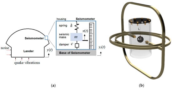
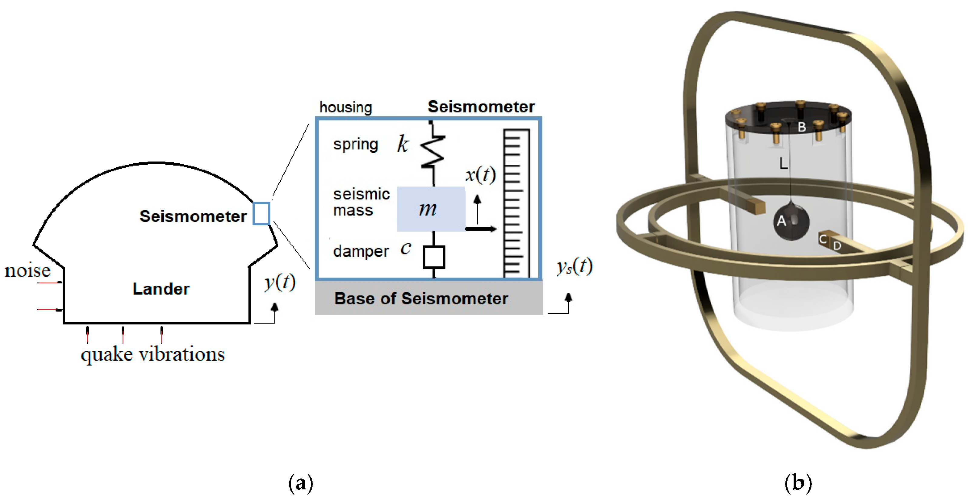
To meet the demanding spectral requirements schematically shown in Figure 2, we designed a pendulum-based assembly that provides both sub-Hz signal magnification and environmental decoupling. The assembly can be lander-mounted (schematics in Figure 3a) or tether-deployed.
Figure 3.
(a) Schematics of the seismometer/lander system. (b) Pendulum-based seismometer mounting design. A: pendulum bob; B: rim of the housing’s top lid. C: housing mounting pivot; D: three-ring gimbal mounting pivot; L: pendulum length.
The design is intended to be sensor-agnostic. The assembly integrates a vertical pendulum housed in a protective cylindrical enclosure. The enclosure can be adapted into a pressure vessel for operation under Venus surface conditions (~460 °C, ~92 bar). Detailed material selection, thermal management, sealing, and long-term survivability are beyond the scope of this work and are not required to assess the proposed mechanical filtering principle or its dynamic performance.
An additional horizontal pendulum may be included to enable vertical motion sensing. To accommodate uneven terrain and landing tilt, both of which degrade seismic sensitivity and antenna alignment, the cylindrical housing can be mounted in a gimbal-ring mechanism (Figure 3b) for passive self-leveling, maintaining gravity alignment during Venus deployment.
A seismic transducer is located at the pendulum’s bob (point A, Figure 3b), to be mechanically isolated from the high-frequency structural resonances from the lander or lander/environment interaction. Through a length-adjustable, stiff arm, the pendulum is suspended from the enclosure’s top lid to function as a passive signal filterer. In Section 3, we will show that the pendulum’s natural frequency can be set below 1 Hz for passively magnifying faint, long-period ground motions, while naturally rejecting higher-frequency disturbances such as wind-induced vibrations. This built-in spectral selectivity removes the need for complex active filtering or exhaustive system modeling.
Table 2 lists the key design parameters, including geometry, material properties, and gimbal dimensions, which were obtained through iterative trials to achieve the desired transmissibility profile in Figure 2. The combination of mechanical simplicity, passive robustness, and adaptability makes this design a promising candidate for future Venus lander missions, as will be demonstrated in the numerical performance evaluation that follows.
Table 2.
Parameters of the pendulum-based seismic amplification design.
3. Results
3.1. Spectral Response of Pendulum-Based Passive Mounting Mechanism
Using the dimensions and material properties listed in Table 2, the spectral response of the mechanical filter was numerically evaluated under white-noise excitation. A random acceleration input with a flat acceleration spectral density (ASD) was applied over the frequency range 0.01–1000 Hz and scaled to yield a root-mean-square (RMS) acceleration of 10 m/s2. The excitation was imposed at the bottom plate when the housing was modeled alone, and at the base of the gimbal when the housing was mounted to the gimbal. Material damping was ignored in all simulations.
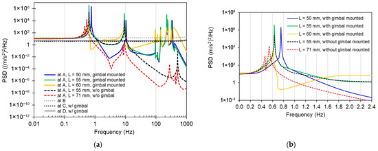
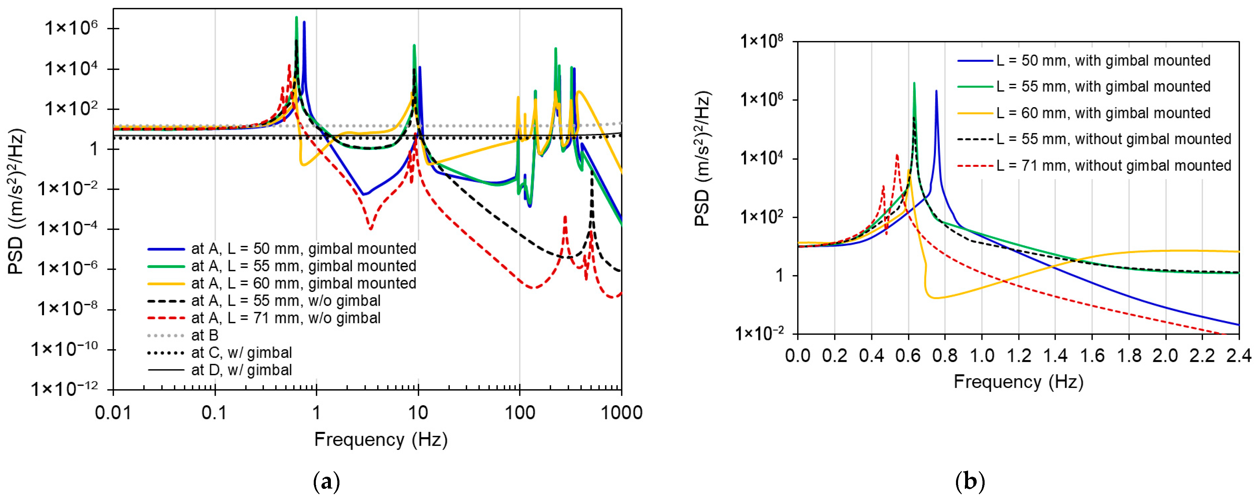
Figure 4 presents the resulting power spectral density (PSD) responses for pendulum lengths of 50, 55, 60, and 71 mm, with and without gimbal mounting. The pendulum length was determined using a two-step approach: a first-order estimate of the standalone pendulum’s natural frequency (≈1.7–2 Hz) established a feasible range, followed by iterative harmonic analysis of the integrated pendulum assembly, with and without the gimbal, to shift the assembly’s fundamental resonance below 1 Hz, as confirmed by the transmissibility results (Section 3.1.3).
Figure 4.
Power spectral densities (PSDs) of the pendulum-based seismometer mounting mechanism. (a) PSD at locations as labeled in Figure 3. (b) Sub-Hz PSD comparison at the pendulum bob.
3.1.1. PSD at Pendulum Bob
The pendulum bob is at Location A in Figure 3. In 0.1–1 Hz, for both the housing-only (non-gimbaled) and gimbal-mounted configurations, all the simulated conditions exhibit a consistent preservation of a high-Q spectral feature across a range of pendulum lengths. This sub-Hz peak frequency will be slightly higher when the gimbal is mounted. Notably, the sub-Hertz peak frequencies remain largely unchanged with arm length variations, indicating that sub-Hz detection is insensitive to pendulum length design. In 1–10 Hz, when not gimbaled, the PSD at the bob of the assembly declines for the non-gimbaled configuration (dashed lines), indicating a strong attenuation of transmitted signals in this range. In contrast, when the gimbal is used (solid lines), the PSD remains flat; thus, it is less effective in attenuating wind noise of 2–3 Hz on Venus than the non-gimbaled system. This is likely due to the gimbal’s compliant structure.
The plots in Figure 4 show a consistent sub-Hz amplification across all simulated configurations. The persistence of these narrowband high-Q peaks, largely unchanged by the inclusion of the cylindrical housing and/or the three-ring gimbal, demonstrates that the sub-Hz resonance behavior is dominated by the pendulum geometry, rather than by secondary structural elements. In this sense, robustness is achieved through mechanical decoupling: the sub-Hertz resonances of interest, which define the sensitivity regime of the seismometer, are physically and dynamically separated from higher-frequency resonances typically associated with gimbal rings, lander structures, and soil stiffness. The probe–gimbal assembly therefore acts as an effective narrowband low-pass filter, attenuating higher-frequency disturbances before they reach the sensor.
The gimbal mounting further mitigates sensitivity to landing orientation and asymmetric contact conditions by preserving the gravitational alignment of the pendulum, as evident by the dashed curves in Figure 4 that exhibit smaller PSD values than those without gimbal mounting. Notably, even in the absence of gimbal mounting, the un-gimbaled configuration behaves as an effective mechanical filter, concentrating sensitivity in the 0.5–0.8 Hz range while providing substantial attenuation above 2 Hz.
Because wind-driven lander vibrations on Venus are expected to preferentially excite structural modes in the 2–4 Hz range, this inherent attenuation of signals above 2 Hz directly suppresses those disturbances before they reach the sensor, providing a robust, fully passive means of rejecting platform-induced noise prior to sensing. This insensitivity and robustness reflect a key requirement for Venus operations, where deployment uncertainties and platform interactions cannot be tightly controlled.
3.1.2. PSD Response at the Mounting Structures (Locations B, C, and D)
The PSD curves for the rim of the top lid (Location B, Figure 3) and the mounting points (Locations C and D) remain spectrally flat in the 0.1–1000 Hz range. These broadband responses neither disrupt vibration transmission nor introduce undesired signal amplification. Numerical simulations indicate that PSD at B is approximately 10% larger than at Location D, which in turn is slightly larger than at location C. These differences are likely attributed to the inherent rigid-body motion of relatively stiff components in the assembly, as explained below.
During vibration, each moving part of the assembly has an instantaneous center of rotation. The kinematic lever-arm effect governs the magnitude of rigid-body motion at a location, scaling with its distance r from its center of rotation. For simplicity, the center of rotation for the rim of the top lid (location B) is approximated as the pivot axis of the housing mount, which lies farther from B than Location D’s center of rotation near the gimbal pivot. Because gimbal rings are typically stiffer in-plane than thin cylindrical walls, the cylindrical housing can ovalize and the lid dish slightly, both of which further amplify the lever-arm effect at B relative to D. Overall, the spectrally constant PSD at these locations indicate that the mounting structure transmits vibrations primarily through rigid-body motion over the 0.1–1000 Hz range, thus confirming that the housing and gimbal do not interfere with the intended sub-Hertz detection. Consequently, sub-Hz seismic signals can propagate freely through the relatively stiff housing and gimbal without distortion.
Collectively, the analyses of the spectral responses at Locations A~D support the design choice of placing the seismometer at the pendulum bob, where the pendulum’s natural low-pass filtering isolates sub-Hertz seismic signals from higher-frequency disturbances.
3.1.3. Transmissibility (Transfer Function)
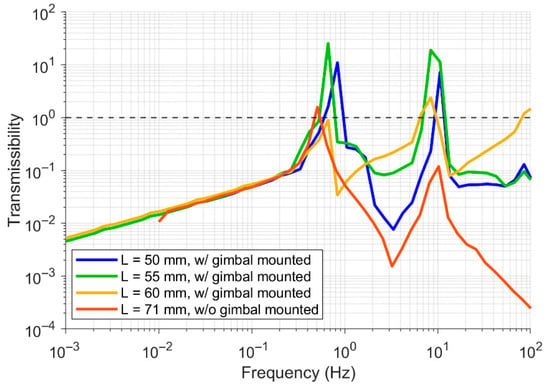
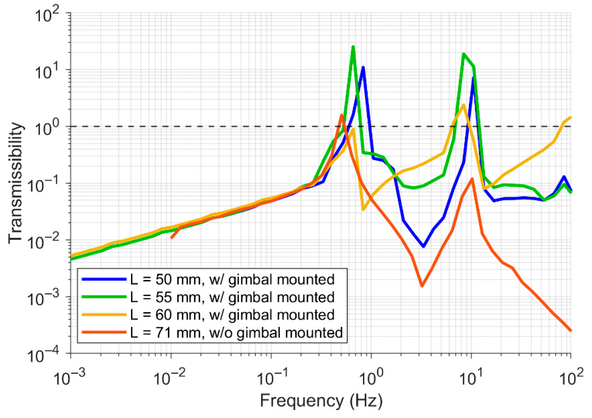
Transmissibility is defined as the ratio of the acceleration at the pendulum’s bob, where the seismometer is located, to that of the input. It effectively represents the system’s input–output transfer function. The acceleration was calculated as the root-mean-squared (RMS) acceleration, calculated by integrating the PSD at a location over 1/3-octave bands centered at logarithmically evenly spaced frequencies. Figure 5 compares the transmissibility of several gimbaled pendulum configurations with varying effective lengths (L = 50 mm, 55 mm, and 60 mm) and un-gimbaled configurations (L = 71 mm). For linear systems under harmonic excitation, the shapes of the displacement and acceleration transmissibility curves are identical, differing only by a frequency-squared scaling factor.
Figure 5.
Transmissibility curves for pendulum-based seismic detection with various pendulum lengths (L = 50–71 mm). Without damping, the apparent closed peaks are artifacts of numerical resolution and curve plotting; the true resonance peaks are open-topped.
In the regime under 0.1 Hz, the transmissibility curves roll off with a linearly increasing gain on a log–log scale regardless of the set configurations. This behavior, inherently attenuating low-frequency signals, is consistent with the characteristics of a vibrational system under base excitation.
In the 0.1–1 Hz regime, the transmissibility curves all display a high Q-factor peak in a very narrow bandwidth. The local amplification around each peak indicates the system’s capacity to magnify ground motion (input excitation), which favors the detection of weak signals within this narrow frequency band while simultaneously attenuating non-target signals. In contrast, the configurations of un-gimbal mounting (L = 71 mm) and gimbaled mounting (L = 60 mm) show generally lower transmissibility across most of the frequency spectrum, implying a reduced frequency sensitivity. A careful design of the central frequency of this sub-Hertz peak is crucial for optimizing SNR. It is noted that the resonance peaks are theoretically open-topped because damping is excluded from the simulation models. The closed or flattened appearance in the plots is a numerical artifact caused by discretized frequency sampling and curve-connecting, which omits fine details near the peaks. For instance, in the un-gimbaled L = 71 mm and gimbaled L = 60 mm configurations, the seemingly lower peaks still correspond to sharp, high-Q resonances with extremely narrow bandwidths—the reduced magnitudes result solely from insufficient frequency resolution, not actual lower amplification.
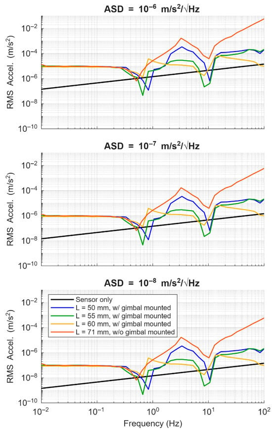
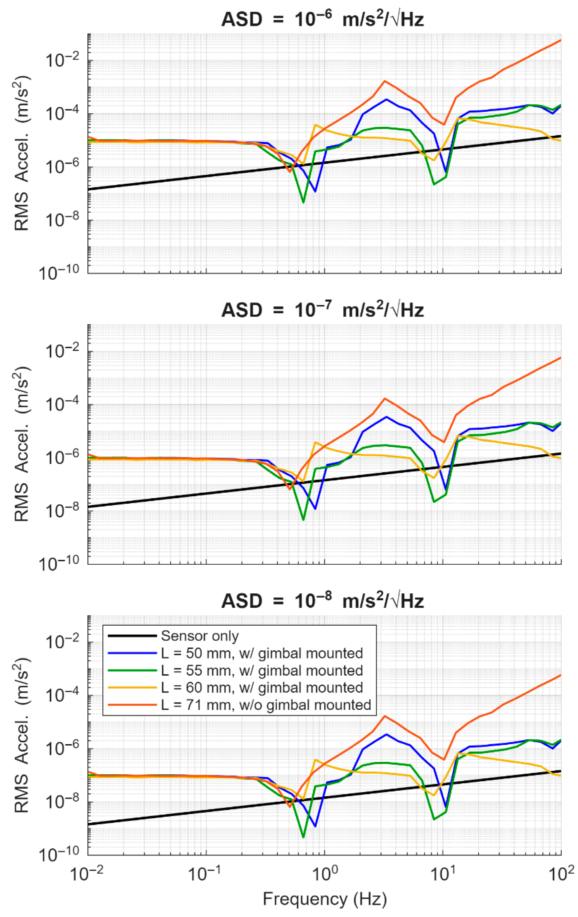
3.2. Minimum Level of Detection
Figure 6 compares the minimum detectable RMS ground acceleration for several passive mounting configurations under three sensor noise floors (ASD = 10−6, 10−7, and 10−8 m/s2/√Hz). Each subplot corresponds to a specific ASD level in the noise floor, enabling direct comparison between a standalone sensor and the various pendulum-mounted designs. Across all noise levels, the curves exhibit the same characteristic behavior: reductions in the sensor noise level (in ASD) uniformly shift the detection threshold downward. This trend is essentially the inverse of the transmissibility behavior shown in Figure 5.
Figure 6.
Minimum detectable ground RMS acceleration for different sensor noise levels (in ASD, as titled), comparing direct deployment with pendulum-mounted configurations. Sensitivity improves near resonances but compromises elsewhere due to signal attenuation.
Within narrow sub-Hz resonant bands, particularly when coupled with the gimbaled suspension, the mechanism can lower the threshold of detectable ground RMS accelerations relative to the sensor alone, across all three noise levels. However, the enhancement is confined to these narrow resonant windows, limiting adaptiveness to broadband or unpredictable signals. This reflects a fundamental trade-off of passive magnification: wave energy is redistributed before reaching the sensor, amplifying signals within the designed resonant band but attenuating others [24]. For instance, the gimbaled L = 60 mm configuration provides a very narrow resonant bandwidth that improves the detection threshold only when signals fall within that band. Such selectivity can be restrictive in environments where seismic frequencies are uncertain. On the other hand, if prior modeling or mission data suggest dominant surface-wave frequencies, as expected for Venus, tuning the mechanical resonance to those bands can strategically enhance detectability where it matters most. Thus, while narrow-band amplification is less adaptive than broadband sensitivity, it offers a viable pathway for planetary seismic detection if resonance features are carefully matched to target signal characteristics.
3.3. Maximum Number of Annual Surface Quake Detectable
The enhanced sensitivity of the gimbaled pendulum-based seismic detector is also evaluated for its capability of reducing the (estimated) minimum number of detectable seismic events per magnitude per year in this section.
The surface-wave magnitude of a given seismic event, , can be directly related to the vertical ground displacement amplitude of period and epicentral distance per [5]:
According to this framework, the maximum detectable epicentral distance defines the maximum surface area over which at least one surface wave magnitude of can be detected. The surface area on a spherical planet of radius can be approximated as a cap area spanned by a cap angle of as:
The ratio between and the planet’s total surface area defines the probability that a seismic event of surface wave magnitude of will occur within . For the case of a single seismic detector deployed on the planet’s surface, detecting at least one such event requires that the global annual number of events be no less than . Accordingly, the minimum annual number of events detectable by a single sensor operating at an observation interval of h hours can be expressed as [5]:
Minimizing hinges on lowering the detection threshold for the displacement amplitude , as detailed below.
Because scales logarithmically with , a slight improvement in ground-motion sensitivity can greatly enlarge the detectable area and lower for a given observation period. Leveraging this principle, the amplification feature of the presented pendulum-based mechanism, when appropriate tuned, can further reduce compared to the sensor-only results of Garcia et al. [5], as shown below.
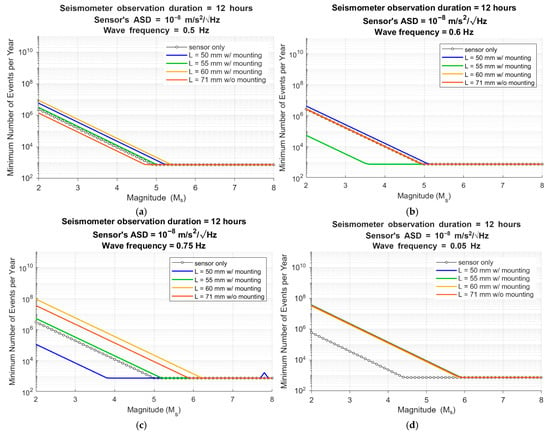
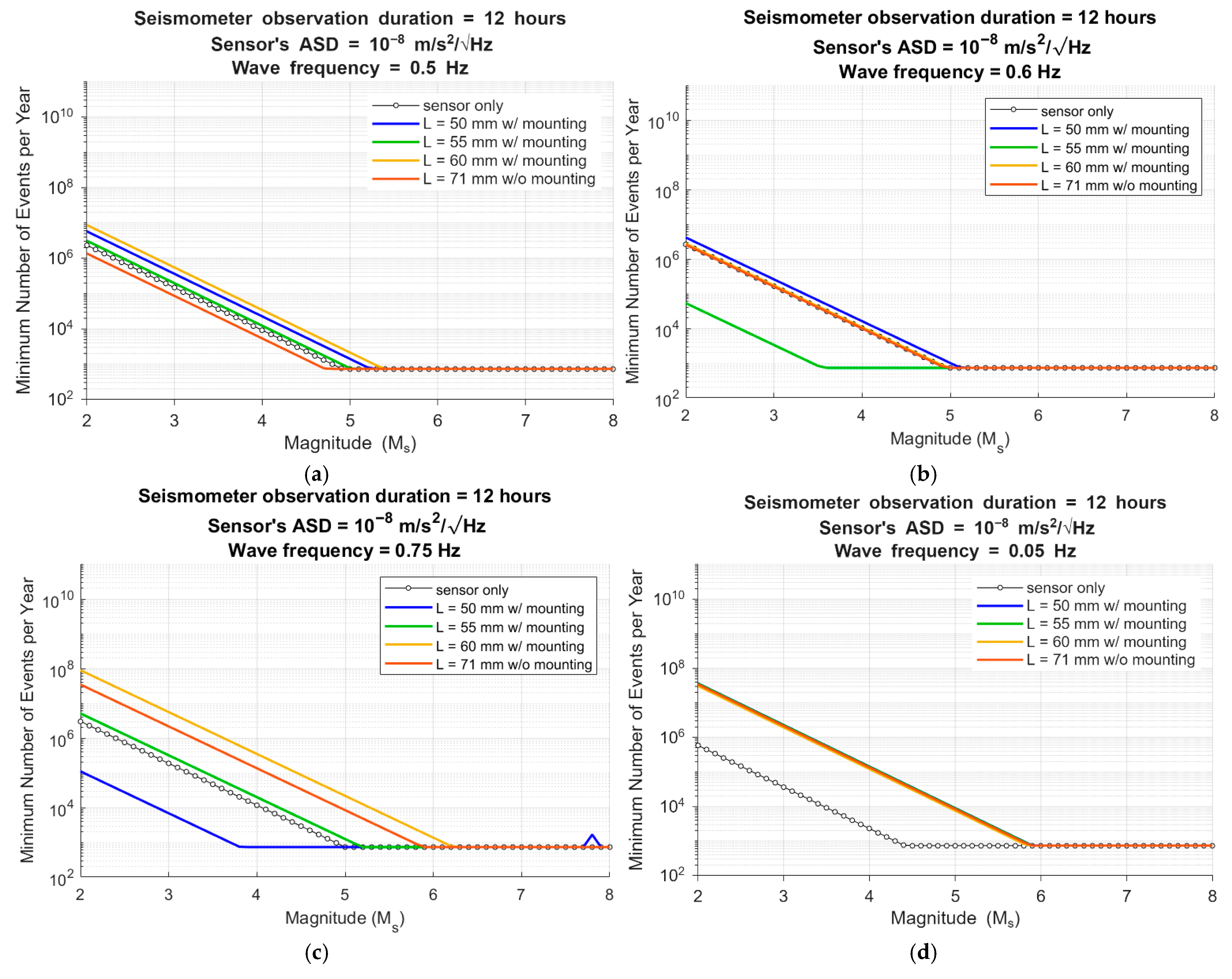
Figure 7 shows the predicted minimum detectable event rates for the 12 h observation window and sensor noise level of 10−8 m/s2/√Hz at wave frequency at 0.5, 0.6, 0.75, and 0.05 Hz. A detection SNR of 3 was used in calculations. At very low frequency, such as 0.05 Hz (Figure 7d), all pendulum-mounted configurations behave nearly identically and perform about two orders of magnitude worse than the baseline “sensor only” case. This reflects quasi-static rigid-body motion of the gimbal–pendulum mechanism, which provides little benefit for very long-period detection.
Figure 7.
Predicted minimum detectable seismic events () for 12 h observation. ASD = 10−8 m/s2/√Hz, and SNR = 3, at wave frequencies of (a) 0.5 Hz, (b) 0.6 Hz, (c) 0.75 Hz, and (d) 0.05 Hz. Curves compare baseline sensor-only (black-dotted) with gimbaled pendulum mounts of length 50 mm (blue), 55 mm (green), 60 mm (orange), and an un-gimbaled 71 mm case (red).
At sub-Hz frequencies (≥0.6 Hz), the gimbaled mounts significantly enhance sensitivity when pendulum lengths are tuned between 50 and 55 mm. In this regime, the minimum detectable event rate improves by 1–2 orders of magnitude relative to the bare sensor, particularly for moderate magnitudes ( in 3–6). This demonstrates an optimal condition in which the passive resonance tuning via the pendulum–gimbal mounting functions effectively. Additional comparative curves are provided in the Supplementary Materials for three representative sensor noise floors in 10−8–10−6 m/s2/√Hz and evaluated at different sub-Hz frequencies near the respective resonant bands.
Across all frequencies, the relative curve shapes are preserved, while absolute values follow approximate power-law scaling:
Details are provided in the Supplementary Materials with benchmarks.
Figure 7 and Figures S2–S5 confirm that passive amplification mechanisms can reduce the minimum detectable event rate by up to two orders of magnitude compared with sensor-alone operation. For example, at a noise floor of 10−7 m/s2/√Hz, a gimbaled pendulum of 50 mm length achieves ~30× higher detection probability than a direct sensor at 2–5 at 0.8 Hz (Figure S2b), while an un-gimbaled pendulum of 71 mm length yields a 2× gain. at 0.5 Hz (Figure S5a). The improvements are concentrated in the 0.1–1 Hz range, coinciding with the spectral content expected for Venusian surface waves.
These results imply clear design tradeoffs. Longer or gimbaled pendula deliver the greatest sensitivity gains but increase structural complexity, while compact un-gimbaled systems offer simpler deployment with moderate (~2×) improvements. From a mission-planning perspective, even modest amplification can allow a 12 h lander to match the detection probability of a standalone sensor operating several days, substantially extending the effective observational yield within the limited lifetime of Venus surface missions.
The design can be refined to broaden robustness and adaptability without losing passivity, by considering (i) multiple staggered resonances (two pendula of different lengths or a compound/branched pendulum), (ii) discrete, field-settable lengths (e.g., pinned holes or a threaded adjustment set pre-deployment), and/or (iii) light damping to trade a bit of peak gain for wider bandwidth. Because improvement grows with ASD, the mount can up-tier lower-cost MEMS toward science-usable thresholds, which is potentially valuable for power/thermal-limited Venus concepts. To address the environmental drift and calibration issue, a more holistic design should consider selecting low-drift materials and in situ calibration taps (or self-noise spectral checks) to track resonance over time. If multiple sensing units were budgeted for operational diversity, stagger their tuned frequencies to hedge environmental uncertainty and increase aggregate bandwidth.
4. Discussions
Although broadband seismology on Earth routinely records wide spectral content and relies on high-dynamic-range digitization plus offline digital filtering to remove high-frequency noise, that approach presumes low instrument thermal drift, high-bandwidth ADCs, and power/thermal margins not available for Venus surface conditions. Broadband inertial sensors and force-feedback designs (e.g., STS/Trillium class instruments) and the associated digitization and processing enable post hoc noise subtraction and instrument correction or calibration on Earth because the analog chain preserves the band of interest at adequate resolution [24]. However, this Earth-based approach will be less feasible on Venus. Venus surface conditions (~460 °C, ~92 bar), stringent power budgets, limited thermal control, and extreme platform-induced vibration/pressure coupling make wide-band, high-dynamic-range acquisition impractical: signals in the 0.5–1 Hz band would be susceptible to ADC saturation, thermal drift and irreversible contamination by platform (e.g., lander) noise before any digital filtering can be applied.
Transmissibility is an intrinsic property of dynamic systems providing a deterministic mapping between input and output spectral quantities, independent of the specific realization of external excitation. This approach enables identification of resonant amplification, attenuation bands, and low-pass filtering behavior without bias toward any specific excitation spectrum. Variations in the excitation spectrum, arising from differences in terrain topology, regolith compliance, or lander-induced structural resonances, enter the system response linearly through the transmissibility (Section 3.1.3), rather than altering the underlying transfer-function characteristics. This predictable input–output behavior satisfies a key operational requirement for Venus surface missions, where deployment conditions and platform interactions cannot be tightly controlled.
In realistic Venus deployments, the effective excitation acting on the passive mechanical filter can include lander-soil interaction, landing orientation, regolith compliance, and terrain topology, and is expected to exhibit a non-uniform, site-dependent PSD with significant uncertainty. By treating such excitation as a stochastic spectral input acting on a deterministic system (e.g., characterized by its transmissibility), established random vibration frameworks [25] can be applied to determine the resulting response in a statistically consistent manner. Within this formulation, the white-noise-based characterization of transmissibility serves as a universal spectral kernel that can be combined with arbitrary, mission-specific input spectra without altering the fundamental filtering behavior of the mechanism. To further reduce sensitivity to lander-induced structural dynamics, the mechanical filter may be mechanically decoupled from the lander through tethered ground deployment and shielding by a wind screen, following deployment strategies demonstrated by the InSight mission on Mars [19].
The present analysis intentionally adopts an idealized, undamped linear model as a first-order framework to establish the feasibility and scaling limits of passive sub-Hertz mechanical amplification under Venus-relevant constraints. This reduces ADC dynamic-range demands and limits sensitivity to the frequencies of scientific interest, thereby improving detectability under Venus surface conditions without relying on wideband electronics or extensive post-processing. We acknowledge that material damping, viscous losses, and thermo-mechanical drift will inevitably reduce the achievable Q-factor and modify resonance characteristics under Venus surface conditions. However, order-of-magnitude estimates based on temperature-dependent structural damping of Ti6Al4V and viscous drag in supercritical CO2 indicate that the total damping ratio in the sub-Hz regime remains small (ζ ≈ 10−3–10−2), with viscous contributions negligible relative to intrinsic material damping. Corresponding shifts in resonant frequency due to damping, thermal expansion, and added-mass effects are estimated to be within ~1%, preserving the sub-Hertz tuning of the mechanism. While damping will reduce peak amplification and broaden the resonance, the fundamental amplification trends and detectability gains reported here remain qualitatively valid. A detailed damping sensitivity and thermo-mechanical stability analysis is therefore deferred to the Supplementary Materials and to future design iterations incorporating compliant pivots and friction-minimized architectures.
The narrowband response of the proposed ultra-high-Q resonant mechanism, with amplification concentrated in the 0.5–0.8 Hz range, is an intentional design choice functioning as a passive mechanical spectral magnifier optimized for sub-Hertz detection under severe mass, power, and environmental constraints. High-Q selectivity enables strong amplification while suppressing higher-frequency noise from lander–structure coupling and environmental disturbances. We nevertheless acknowledge that the dominant spectral content of Venusian surface waves remains uncertain across approximately 0.01–1 Hz, and that a design of single fixed-frequency resonance cannot ensure spectral alignment in all scenarios.
To quantify this uncertainty, a preliminary probabilistic sensitivity analysis is performed, in which the dominant Venusquake spectral peak is modeled as log-uniformly distributed over the interval 0.01–1 Hz. For an array of N narrowband resonators, each with a half-power bandwidth centered at a different resonance deliberately staggered in 0.01–1 Hz, the probability of complete spectral mismatch can be estimated as (see the Supplementary Material for derivation details):
where Q is the resonator quality factor, 1 Hz, 0.01 Hz, and represents a possible effective bandwidth widening introduced through weak stiffness nonlinearity in the resonator.
This analysis indicates that spectral mismatch risk decreases linearly with the number of spectrally staggered resonators and can be further reduced through modest passive bandwidth broadening. Accordingly, future extensions of this concept may incorporate arrays of mechanically similar but frequency-staggered resonators (N > 1), such as fork-like or multi-arm pendulum architectures, to provide overlapping narrowband coverage while preserving high-Q amplification. Alternatively, replacing the mechanical hinge with compliant mechanisms engineered to exhibit multiple closely spaced sub-Hertz modes or flattened resonance responses (with ) can enhance bandwidth robustness while remaining fully passive. Collectively, these strategies mitigate spectral uncertainty without reliance on active tuning, adaptive control, or additional power consumption.
5. Conclusions
Understanding the spectral correlation between the ground excitation and the sensor’s response is essential for achieving sensitive detection of desired seismic signals while minimizing noise. This paper presented a passive, mechanically tuned methodology to enhance the sensitivity of an integrated lander/seismometer system for Venusquake detection in the 0.1–1 Hz range, while attenuating higher-frequency disturbances. The main achievements and advantages of this study are:
- A desired transfer function (transmissibility) is formulated as a system-level criterion for spectral amplification and noise attenuation.
- A pendulum-based sensor-mounting mechanism is developed to realize the formulated transmissibility, enabling two high-Q peaks in the 0.5–0.8 Hz range that can amplify weak seismic signals in the sub-Hertz range.
- A self-leveling mechanism ensures adaptive vertical alignment and attenuates signals above 1 Hz, adding robustness of the system to lander orientation and structure-environment induced noises.
- The effects of damping are comprehensively justified through order-of-magnitude and sensitivity analyses, showing that realistic dissipation modifies amplification magnitude without altering the fundamental transmissibility trends.
- Narrowband peak sensitivity is analyzed to assess detectability under spectral uncertainty, establishing the criteria with which high-Q amplification remains effective and motivating architectural extensions for broader detectability.
- Compared with existing approaches that rely on broadband sensors combined with electronic filtering, active leveling, or complex deployment systems, the proposed design achieves spectral selectivity, orientation robustness, and noise attenuation entirely through passive mechanical means, without additional power consumption or active control.
Future extensions will address spectral uncertainty through arrays of frequency-staggered resonators or compliant mechanisms with weak stiffness nonlinearity, enabling enhanced bandwidth robustness while retaining the advantages of high-Q passive amplification.
Supplementary Materials
The following supporting information can be downloaded at: https://www.mdpi.com/article/10.3390/j9010006/s1. It cites [19,21,22,23,24,25,26,27,28,29,30,31,32,33,34]. Figure S1: Schematics of the seismometer/lander coupled system. The lander vibrates in response to quake waves and environmental noise, which then triggers the seismometer to respond; Figure S2. Comparison of baseline sensor-only performance (dotted curves) with gimbaled pendulum mounts of length 50 mm (solid curves). Shown are the predicted minimum detectable seismic events, , for 12-h observation and SNR = 3, for three ASD levels of 10−8–10−6 m/s2/√Hz, at wave frequencies of (a) 0.6 Hz, (b) 0.8 Hz, and (c) 0.95 Hz. Figure S3. Comparison of baseline sensor-only performance (dotted curves) with gimbaled pendulum mounts of length 55 mm (solid curves). Shown are the predicted minimum detectable seismic events, , for 12-h observation and SNR = 3, for three ASD levels of 10−8–10−6 m/s2/√Hz, at wave frequencies of (a) 0.55 Hz, (b) 0.65 Hz, and (c) 0.75 Hz. Figure S4. Comparison of baseline sensor-only performance (dotted curves) with gimbaled pendulum mounts of length 60 mm (solid curves). Shown are the predicted minimum detectable seismic events, , for 12-h observation and SNR = 3, for three ASD levels of 10−8–10−6 m/s2/√Hz, at wave frequencies of (a) 0.5 Hz, (b) 0.63 Hz, and (c) 0.7 Hz. Figure S5. Comparison of baseline sensor-only performance (dotted curves) with gimbaled pendulum mounts of length 71 mm (solid curves). Shown are the predicted minimum detectable seismic events, , for 12-h observation and SNR = 3, for three ASD levels of 10−8–10−6 m/s2/√Hz, at wave frequencies of (a) 0.5 Hz, (b) 0.6 Hz, and (c) 0.65 Hz.
Author Contributions
Conceptualization, C.-f.C. and M.O.; methodology, C.-f.C. and M.O.; software, C.-f.C., M.O. and N. S.; validation, C.-f.C., M.O. and N.S.; formal analysis, C.-f.C., M.O. and N. S.; investigation, C.-f.C., M.O. and N. S.; resources, C.-f.C.; data curation, C.-f.C.; writing—original draft preparation, C.-f.C., M.O. and N. S.; writing—review and editing, C.-f.C.; visualization, C.-f.C.; supervision, C.-f.C.; project administration, C.-f.C. All authors have read and agreed to the published version of the manuscript.
Funding
This research received no external funding.
Institutional Review Board Statement
Not applicable.
Informed Consent Statement
Not applicable.
Data Availability Statement
The raw data supporting the conclusions of this article will be made available by the authors on request.
Acknowledgments
The authors thank Robert R. Herrick (Institute of Northern Engineering, University of Alaska Fairbanks) for his thorough review of, and insightful comments on, this manuscript. We also express our gratitude to the anonymous reviewers; their constructive suggestions and criticisms have greatly improved the quality and clarity of this work.
Conflicts of Interest
The authors declare no conflicts of interest.
Abbreviations
The following abbreviations are used in this manuscript:
| ADC | Analog-to-digital conversion |
| ASD | Amplitude spectrum density |
| GSN | Global seismographic network |
| PSD | Power spectrum density |
| RMS | Root-mean-squared |
| SNR | Signal-to-noise ratio |
| NASA Missions: | |
| DAVINCI | Deep Atmosphere Venus Investigation of Noble gases, Chemistry, and Imaging |
| InSAR | Interferometric Synthetic Aperture Radar |
| LLISSE | Long Lived In situ Solar System Explorer |
| SEIS | Seismic Experiment for Interior Structure |
| SAEVe | Seismic and Atmospheric Exploration of Venus |
| VERITAS | Venus Emissivity, Radio Science, InSAR, Topography, and Spectroscopy |
References
- Kremic, T.; Ghail, R.; Gilmore, M.; Hunter, G.; Kiefer, W.; Limaye, S.; Pauken, M.; Tolbert, C.; Wilson, C. Long-duration Venus lander for seismic and atmospheric science. Planet Space Sci. 2020, 190, 104961. [Google Scholar] [CrossRef] [Scilit]
- Rolf, T.; Weller, M.; Gülcher, A.; Byrne, P.; O’rourke, J.G.; Herrick, R.; Bjonnes, E.; Davaille, A.; Ghail, R.; Gillmann, C.; et al. Dynamics and Evolution of Venus’ Mantle Through Time. Space Sci. Rev. 2022, 218, 70. [Google Scholar] [CrossRef] [Scilit]
- Herrick, R.R.; Hensley, S. Surface changes observed on a Venusian volcano during the Magellan mission. Science (1979) 2023, 379, 1205–1208. [Google Scholar] [CrossRef] [Scilit]
- Lognonné, P.; Johnson, C.L. Planetary Seismology. In Treatise on Geophysics, 2nd ed.; Elsevier: Oxford, UK, 2015; Volume 10, pp. 65–120. [Google Scholar]
- Garcia, R.F.; van Zelst, I.; Kawamura, T.; Näsholm, S.P.; Horleston, A.; Klaasen, S.; Lefèvre, M.; Solberg, C.M.; Smolinski, K.T.; Plesa, A.-C.; et al. Seismic Wave Detectability on Venus Using Ground Deformation Sensors, Infrasound Sensors on Balloons and Airglow Imagers. Earth Space Sci. 2024, 11, e2024EA003670. [Google Scholar] [CrossRef] [Scilit]
- van Zelst, I.; De Toffoli, B.; Garcia, R.F.; Ghail, R.; Gülcher, A.J.P.; Horleston, A.; Kawamura, T.; Klaasen, S.; Lefevre, M.; Lognonné, P.; et al. Seismicity on Venus: Optimal Detection Methods and Target Regions; European Geosciences Union General Assembly (EGUGA): Vienna, Austria, 2024; p. 12790. Available online: https://ui.adsabs.harvard.edu/abs/2024EGUGA..2612790V/abstract?bbbRedirect=1 (accessed on 2 October 2025).
- Butler, R.; Lay, T.; Creager, K.; Earl, P.; Fischer, K.; Gaherty, J.; Laske, G.; Leith, B.; Park, J.; Ritzwolle, M.; et al. The Global Seismographic Network Surpasses Its Design Goal. EOS Trans. AGU 2004, 85, 225–229. [Google Scholar] [CrossRef] [Scilit]
- Froment, M.; Brissaud, Q.; Näsholm, S.P.; Schweitzer, J. Balloon seismology enables subsurface inversion without ground stations. Commun. Earth Environ. 2025, 6, 949. [Google Scholar] [CrossRef] [Scilit]
- Tanimoto, T.; Anderson, A. Seismic noise between 0.003 Hz and 1.0 Hz and its classification. Prog. Earth Planet. Sci. 2023, 10, 56. [Google Scholar] [CrossRef] [Scilit]
- Nishida, K. Ambient seismic wave field. Proc. Jpn. Acad. Ser. B Phys. Biol. Sci. 2017, 93, 423. [Google Scholar] [CrossRef] [Scilit]
- Smrekar, S.; Dyar, D.; Helbert, J.; Hensley, S.; Nunes, D.; Whitten, J. VERITAS (Venus Emissivity, Radio Science, InSAR, Topography and Spectroscopy): A Proposed Discovery Mission; Europlanet Science Congress (EPSC): Brussels, Belgium, 2020; p. EPSC2020. Available online: https://ui.adsabs.harvard.edu/abs/2020EPSC...14..447S/abstract (accessed on 2 October 2025).
- Garvin, J.B.; Getty, S.A.; Arney, G.N.; Johnson, N.M.; Kohler, E.; Schwer, K.O.; Sekerak, M.; Bartels, A.; Saylor, R.S.; Elliott, V.E.; et al. Revealing the Mysteries of Venus: The DAVINCI Mission. Planet Sci. J. 2022, 3, 117. [Google Scholar] [CrossRef] [Scilit]
- Krishnamoorthy, S.; Komjathy, A.; Pauken, M.T.; Cutts, J.A.; Garcia, R.F.; Mimoun, D.; Cadu, A.; Sournac, A.; Jackson, J.M.; Lai, V.H.; et al. Detection of Artificially Generated Seismic Signals Using Balloon-Borne Infrasound Sensors. Geophys. Res. Lett. 2018, 45, 3393–3403. [Google Scholar] [CrossRef] [Scilit]
- Panning, M.P.; Pike, W.T.; Lognonné, P.; Banerdt, W.B.; Murdoch, N.; Banfield, D.; Charalambous, C.; Kedar, S.; Lorenz, R.D.; Marusiak, A.G.; et al. On-Deck Seismology: Lessons from InSight for Future Planetary Seismology. J. Geophys. Res. Planets 2020, 125, e2019JE006353. [Google Scholar] [CrossRef] [Scilit]
- Sun, W.; Tkalčić, H.; Chen, J.; Wang, S. Spectral characteristics and implications of located low-frequency marsquakes and impact events from InSight SEIS observations. Phys. Earth Planet. Inter. 2025, 361, 107334. [Google Scholar] [CrossRef] [Scilit]
- Banerdt, B. EPSC Abstracts: InSight’s Contributions to Planetary Seismology and Geophysics. Eur. Sci. Congr. 2022, 16, 773. [Google Scholar]
- Ksanfomaliti, L.V.; Zubkova, V.M.; Morozov, N.A.; Petrova, E.V. Microseisms at the VENERA-13 and VENERA-14 Landing Sites. Sov. Astron. Lett. 1982, 8, 241–242. [Google Scholar]
- Kremic, T.; Hunter, G.W. Long-Lived In-Situ Solar System Explorer (LLISSE) Potential Contributions to Solar System Exploration. Bull. Am. Astron. Soc. 2021, 53, 151. [Google Scholar]
- Lognonné, P.; Banerdt, W.B.; Giardini, D.; Pike, W.T.; Christensen, U.; Laudet, P.; De Raucourt, S.; Zweifel, P.; Calcutt, S.; Bierwirth, M.; et al. SEIS: Insight’s Seismic Experiment for Internal Structure of Mars. Space Sci. Rev. 2019, 215, 12. [Google Scholar] [CrossRef] [Scilit] [PubMed]
- Schon, K. Transfer behavior of linear systems, convolution and deconvolution. In High Voltage Measurement Techniques: Fundamentals, Measuring Instruments, and Measuring Methods; Springer International Publishing: Cham, Switzerland, 2019; pp. 269–306. [Google Scholar]
- Murdoch, N.; Mimoun, D.; Garcia, R.F.; Rapin, W.; Kawamura, T.; Lognonné, P.; Banfield, D.; Banerdt, W.B. Evaluating the Wind-Induced Mechanical Noise on the InSight Seismometers. Space Sci. Rev. 2017, 211, 429–455. [Google Scholar] [CrossRef] [Scilit]
- Murdoch, N.; Alazard, D.; Knapmeyer-Endrun, B.; Teanby, N.A.; Myhill, R. Flexible Mode Modelling of the InSight Lander and Consequences for the SEIS Instrument. Space Sci. Rev. 2018, 214, 117. [Google Scholar] [CrossRef] [Scilit]
- Stott, A.E.; Charalambous, C.; Warren, T.J.; Pike, W.T.; Myhill, R.; Murdoch, N.; McClean, J.B.; Trebi-Ollennu, A.; Lim, G.; Garcia, R.F.; et al. The Site Tilt and Lander Transfer Function from the Short-Period Seismometer of InSight on Mars. Bull. Seismol. Soc. Am. 2021, 111, 2889–2908. [Google Scholar] [CrossRef] [Scilit]
- Lavelle, F.; Bergman, L.; Spanos, P. Seismic response spectra of a combined system by Green’s functions. Soil Dyn. Earthq. Eng. 1991, 10, 93–100. [Google Scholar] [CrossRef] [Scilit]
- Ackerley, N. Principles of Broadband Seismometry. In Encyclopedia of Earthquake Engineering; Springer: Berlin/Heidelberg, Germany, 2015; pp. 1941–1970. [Google Scholar] [CrossRef] [Scilit]
- Spanos, P.; Lutes, L. A Primer of Random Vibration Techniques in Structural Engineering. Shock. Vib. Dig. 1986, 18, 3–9. [Google Scholar] [CrossRef] [Scilit]
- Fayon, L.; Knapmeyer-Endrun, B.; Lognonné, P.; Bierwirth, M.; Kramer, A.; Delage, P.; Karakostas, F.; Kedar, S.; Murdoch, N.; Garcia, R.F.; et al. A Numerical Model of the SEIS Leveling System Transfer Matrix and Resonances: Application to SEIS Rotational Seismology and Dynamic Ground Interaction. Space Sci. Rev. 2018, 214, 119. [Google Scholar] [CrossRef] [Scilit]
- Panning, M.P.; Kedar, S. Seismic response of the Mars Curiosity Rover: Implications for future planetary seismology. Icarus 2019, 317, 373–378. [Google Scholar] [CrossRef] [Scilit]
- Lorenz, R.D.; Shiraishi, H.; Panning, M.; Sotzen, K. Wind and surface roughness considerations for seismic instrumentation on a relocatable lander for Titan. Planet. Space Sci. 2021, 206. [Google Scholar] [CrossRef] [Scilit]
- Kwiatek, G.; Ben-Zion, Y. Theoretical limits on detection and analysis of small earthquakes. J. Geophys. Res. Solid Earth 2016, 121, 5898–5916. [Google Scholar] [CrossRef] [Scilit]
- Lee, Y.; Welsch, G. Young’s modulus and damping of Ti-6Al-4V alloy as a function of heat treatment and oxygen concentration. Mater. Sci. Eng. A 1990, 128, 77–89. [Google Scholar] [CrossRef] [Scilit]
- Brennen, C.E. A Review of Added Mass and Fluid Inertial Forces; Naval Civil Engineering Laboratory: Port Hueneme, CA, USA, 1981. [Google Scholar]
- Bai, R.; Zhang, H.; Yang, N.; Yu, Z.; Li, B.; Xu, Q.; Chen, G. Optimization of a near-zero-center-shift compliant pivot for large motion range and high bearing stiffness. Mech. Mach. Theory 2025, 216, 106218. [Google Scholar] [CrossRef] [Scilit]
- Blad, T.; van Ostayen, R.A.; Herder, J.L.; Tolou, N. A Statically Balanced Compliant Ortho-Planar Mechanism for Low-Frequency Energy Harvesting. J. Mech. Des. 2022, 144, 073302. [Google Scholar] [CrossRef] [Scilit]

Disclaimer/Publisher’s Note: The statements, opinions and data contained in all publications are solely those of the individual author(s) and contributor(s) and not of MDPI and/or the editor(s). MDPI and/or the editor(s) disclaim responsibility for any injury to people or property resulting from any ideas, methods, instructions or products referred to in the content. |
© 2026 by the authors. Licensee MDPI, Basel, Switzerland. This article is an open access article distributed under the terms and conditions of the Creative Commons Attribution (CC BY) license.