1. Introduction
The European Green Deal aims to make Europe the first carbon-neutral continent by 2050 and to reduce greenhouse gas emissions by at least 55% by 2030 [
1]. These goals are achievable through a broad energy transition in different sectors. Five emission sectors have been identified, and in Europe, the main one is transport (28%) [
2]. The widely studied and debated energy transition will bring many benefits, such as increased energy reliability, economic growth, and job creation [
3,
4]. Gielen et al. pointed out that the use of renewable energies, and improved conversion factor, together with the electrification of end uses, account for 94% of emission reductions [
3]. Although energy use for heating has remained stable since 2010, production systems are mostly powered by fossil fuels. The share powered by renewable energy was around 20% in 2019 [
5]. To reach the goals of the Sustainable Development Scenario (SDS), clean energy technologies must exceed 50% of new heating equipment sales by 2030 [
6]. Heating and hot water account for 79% of total final energy use in EU countries [
7]. Solar energy, in particular concentrated solar power (CSP), can play a crucial role in this context, especially for district heating networks [
8,
9,
10,
11]. Solar energy is used in solar district heating (SDH) projects across Europe, contributing up to 20% of annual heat demand, and potentially more with seasonal storage [
12]. Among CSP technologies, the dish system offers high thermal efficiency for medium-to-high temperatures and is suitable for high-temperature applications [
13]. Efficient energy conversion is achieved with sun-tracking parabolic dish collectors and cavity receivers, minimizing heat losses [
14]. Parabolic collectors show superior energy conversion efficiency among CSP systems, as studied by Coventry et al. [
15]. However, each dish has a relatively low heat output, often in the order of tens of kilowatts. A positive aspect is the possibility of producing thermal and electrical energy in a combined manner. These features make dishes particularly interesting for domestic applications, small buildings, and local communities. However, dish technology is not widely adopted, and the stability of conversion efficiency needs to be extended to increase commercial penetration [
16]. Only a few studies focus on the heating part of CSPs [
15,
17,
18]. Coventry et al. highlighted the operation of thermal energy of a CSP system (2016), where an output of the system in addition to electricity is also the production of pressurised hot water, which can be used in a thermal energy distribution network [
15]. This study is mainly concerned with evaluating the performance of an existing CSP dish located at the Energy Center of Turin. One of the main objectives of this study is to evaluate the production of thermal energy in the winter and autumn seasons. The solar concentrator has its normal operation in producing electricity from the accumulation of concentrated solar radiation in the receiver. This occurs most easily in the seasons from spring to autumn. The production of thermal energy is a surplus that is added to the production of electricity [
19,
20,
21,
22]. In this study, the CSP dish is integrated with a water storage tank, forming a system designed to provide hot water for integration into the Energy Centre’s network. In the second part of the paper, a comprehensive life cycle analysis (LCA) will be conducted on the key components of the entire system used. In particular, the proposed configuration does not incorporate any fossil-based backup heating sources, ensuring no pollutant emissions during the system operation. Thus, the innovative part of the study concerns not only the production of renewable energy from concentrated solar power, but also the life cycle analysis for each plant component. In this analysis, the solar collector, the solar receiver, the domestic hot water tank, and the piping system are included.
2. Material and Methods
The concentrator consists of a single solar dish with an aperture of approximately 2.4 m (Elma net. Srl, Trento, Italy). The system is composed of two motors to allow optimal orientation according to the time of day, and from the geographical coordinates of the site where the CSP is installed (Turin, 45.0676° N, 7.6563° E). Other useful geometric and technical parameters are listed in the following table (
Table 1) and in previous studies [
21,
23].
The concentrator–receiver system is built using the Comsol Multiphysics 5.6 Inc. software (Burlington, MA, USA). In this study, the global irradiance varied from 350 to 800 W/m
2, in the autumn and winter seasons. This value is derived from previous experimental measurements conducted in the plant and recently published [
19]. If the dish were a perfect reflector, i.e., if all incoming radiation were reflected specularly, if the dish were perfectly smooth, and if the sun’s rays behaved as planar waveforms from an infinitely distant point source, all incoming rays would focus on a single point in the collector—in the focus of the paraboloid. To make the system more realistic, some deviations from the ideal case were included in the analysed model:
Part of the incident radiation is absorbed by the dish. In this model, the absorption coefficient is set to 0.1, which means that 90% of the incoming radiation is reflected [
24].
Not all incident rays will be parallel; on the contrary, incident rays are sampled by a narrow cone with a maximum angle, 𝜓𝑚, of 4.56 mrad [
24]. A part of the radiation is also emitted from the circumsolar region surrounding the solar disc, instead of from the solar disc itself, but this radiation is neglected in the present model, i.e., a circumsolar ratio (CSR) of zero is assumed.
The reflected rays are not all released in the same direction because the surface of the parabola is not smooth. Instead, the normal to the surface is perturbed by an additional angle that is sampled by a Rayleigh distribution. This optical error is considered with a surface tilt error of 1.75 mrad [
24].
The limb-darkening effect is considered to consider the variation in power of rays from different regions of the Sun. Rays emitted from the centre are more intense than those emitted from the peripheral regions of the solar disc.
Rays are released from 250,000 distinct points (limitations due to computational costs influenced by the nature of the computer).
The limb-darkening effect is used to consider the non-uniform distribution of solar radiation across the solar disc, considering that the intensity of sunlight varies from the centre to the outer regions of the solar disc. This variation can be influenced by factors such as the angle of incidence and the solar temperature profile.
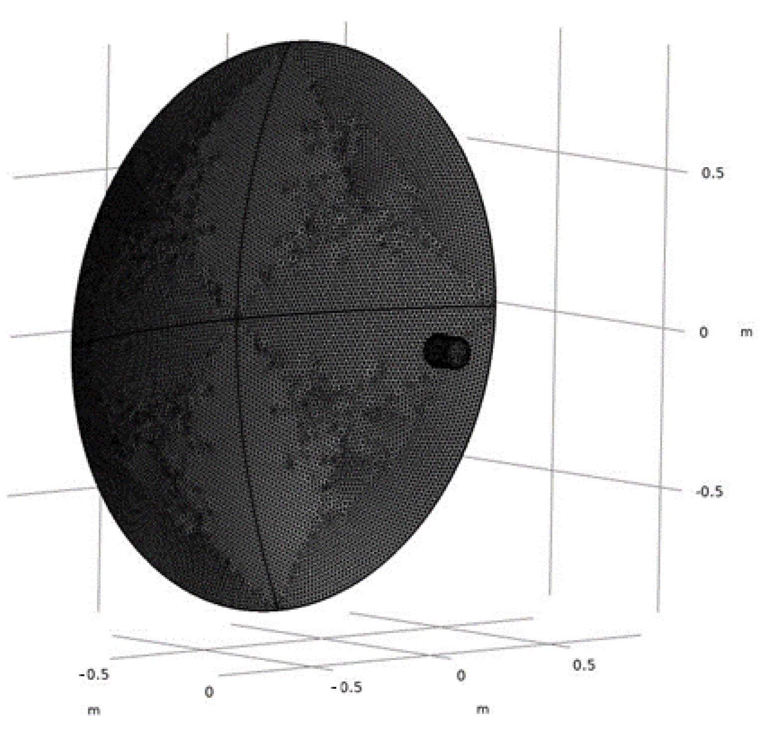
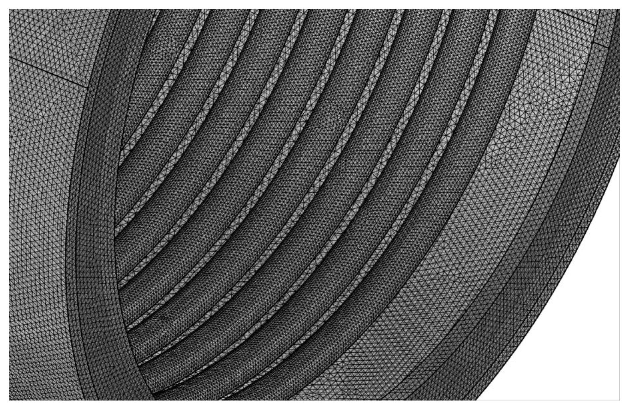
In the present study, a cavity solar receiver was chosen for its simplicity and ease of fabrication, see
Figure 1 and
Figure 2. The mesh must have a higher resolution on curved surfaces to accurately represent the surface normal. On the other hand, the mesh on flat surfaces can be coarser. A fine mesh on curved surfaces improves the accuracy of the reinitialised wave vectors of reflected and refracted rays [
25]. To reduce the mesh size on the curved surfaces without creating superfluous meshes, 0.2 as the curvature factor was selected. Furthermore, since the main objective is to determine the temperature distribution within the receiver, a customised free triangular mesh was used on the receiver with a maximum element size of 0.0002 [mm] and a minimum element size of 0.00004 [mm].
The shape and dimensions of the receiver, the solar absorptance of its inner surface, and the type of reflection on its inner surface, in conjunction with the parameters introduced earlier, collectively influence the uneven absorption of heat flux by the receiver’s inner surface. These factors play a crucial role in determining the actual distribution of absorbed radiant flux density.
The mesh independence analysis was accomplished using the same procedure reported in Marra et al. [
19]. The model built was validated with experimental temperature measured inside the receiver structure using a B-type thermocouple (Tersid srl, Milan, Italy) [
26]. The system modelled (CSP + cavity receiver) is connected to a water storage tank to meet the hot water needs for a single family of four persons, for more details refer to [
27]. Thermal demand for domestic hot water is expressed by the following equation:
where
is daily demand of DHW in
; and temperature,
can be generally assumed to be in the range of
. However, temperature from the aqueduct is related to the average temperature of the ground at
depth. In Italy,
varies between
in the Po valley. The demand for the DHW is equal to around
,
or
for the selected case study. An important aspect related to the performance of a TES is maintaining a high degree of stratification of the reactor volume connected to the users. Thermal stratification allows a limited operation of auxiliary energy supply. For sensible TES, the lower and upper-temperature limits determine the maximum capacity stored. Thus, maximum storage capacities are not accessible in real storage systems [
28].
The size of the storage is based on the following equation:
where
is the thermal energy demand,
is the maximum temperature in the tank (
for non-pressurized water tank), and
is the minimum temperature for satisfying the demand (
) [
28]. In this study, the maximum tank temperature was set at 80 °C (to prevent legionella) and the minimum at 45 °C, and, using the previously calculated hot water demand, a volume of 190 L was sufficient. The energy demand for heating this volume of water can be evaluated by the following equation:
where
is the amount of thermal energy required to heat water,
is the water tank volume,
is the specific heat of the water, and
is equal to 15 °C.
In the second part of the paper, a life cycle analysis was performed. Despite the widespread use of concentrated solar power plants, their environmental assessment is still little investigated. Reviewing the literature studies on the LCA of CSP, it can be seen that most of the references concern CSP plants based on parabolic troughs and solar tower technology [
29,
30,
31]. Leamnatou et al. state that the impact of CSP plants depends on the use of water and the materials used for storage. Carnevale et al. presented a general case of LCA of solar energy systems [
32,
33]. By reviewing the literature, further investigations are needed on plate systems, storage materials, water-saving strategies, and the soiling effect, for even small systems focused on small CSP systems.
This analysis aims to study the impacts of a solar dish (CSP) used for cradle-to-grave energy production, as no similar studies exist in the literature. The LCA analysis is performed on the macro-components of the system. These components are the solar dish, the solar receiver, the water storage tank, and the piping. This choice is due to several limitations, one of which is the database used. Since the database has limited sources, the electronic components were excluded from the analysis—the same applies to the soldering of the parts. The functional unit chosen in this study is “a hot water tank”, and, following ISO standards 14040 and 14044, the results of the LCA are expressed in terms of this functional unit.
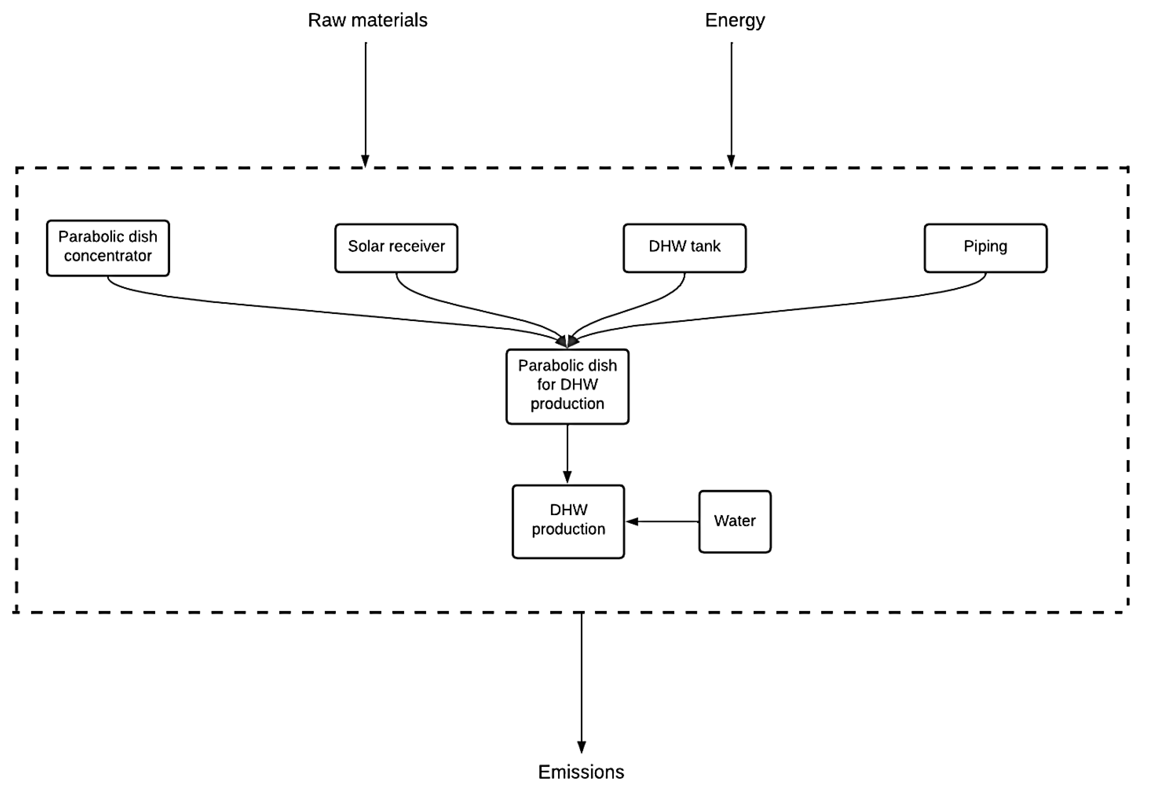
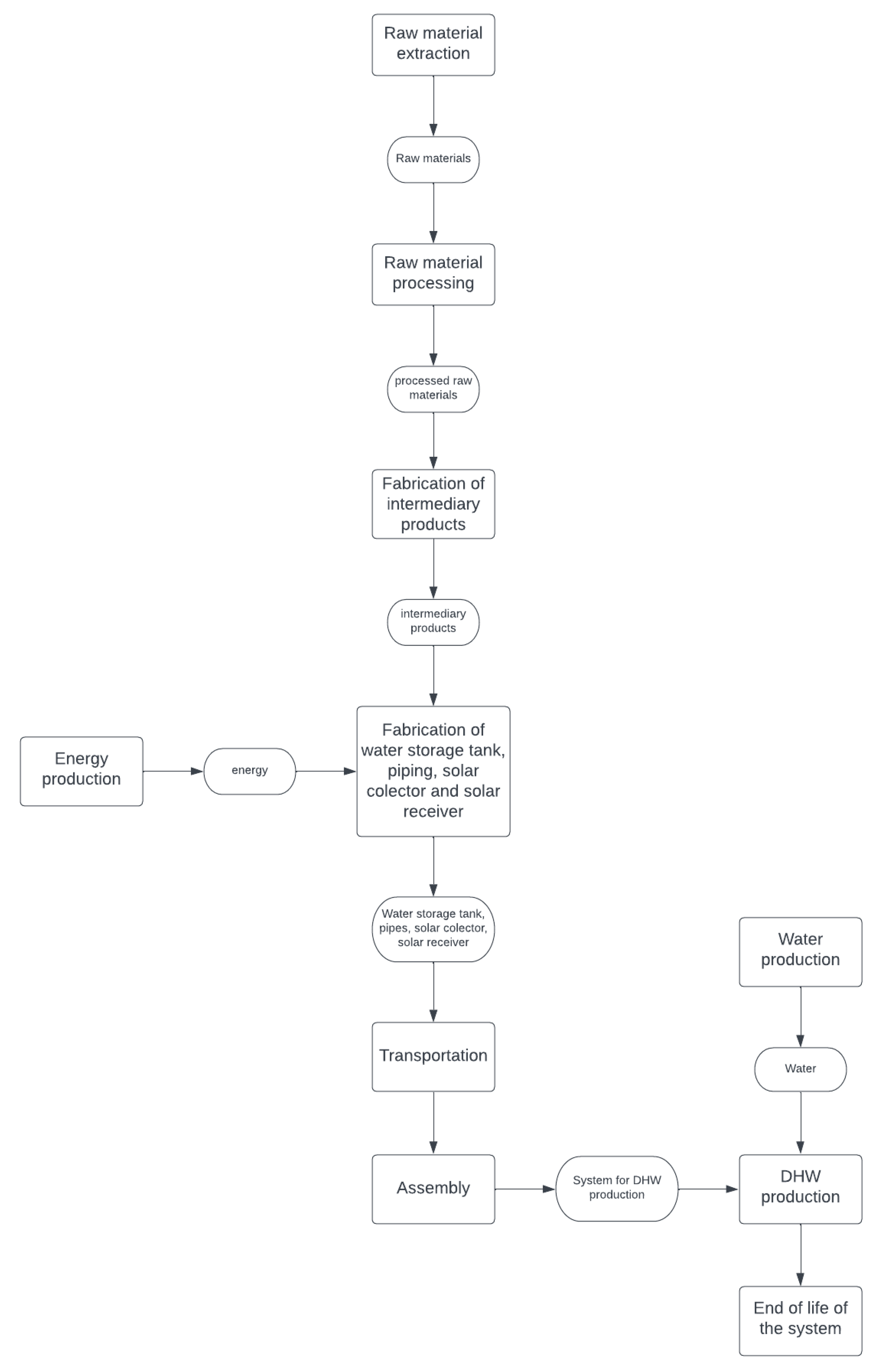
The system boundary shown in
Figure 3 includes the production, utilisation, and final decommissioning phases. Four different processes were considered separately to produce the system.
Each process includes raw material extraction and end-of-life treatment. The process “parabola for hot water production” represents a process that includes all the outputs of the previous processes. It includes four upstream processes as inputs and their transport from the production site to the utilisation site. The output of the process “parabola for domestic hot water production” is the input of “domestic hot water production”, together with “water”. The last process is the functional unit to which all results will be referred: a domestic hot water tank. In this last process, which represents the utilisation phase, water consumption is also included. In this case, the transport of water from the extraction source to the point of use is not considered. The manufacturing processes of the hot water tank, receiver, piping, and solar collector do not include the impacts of their assembly. These impacts were omitted due to a lack of reliable data. Furthermore, due to the difficulty of finding accurate information on the quantities of materials used, the analysis was based on product data sheets and estimates from the literature. The life expectancy of the components is assumed to be 30 years (30 years × 365 days per year = 10,950 days). If the tank operates for 255 days per year (due to non-continuous use for 12 months) and considering, the previously introduced functional unit “a domestic hot water tank”, the weight of one day of operation is equal to 0.000131 of the life expectancy (1/7650 days (7650 days = 30 years × 255 days/year)), see
Figure 4. Certainly, within the lifetime estimated by the manufacturer of the solar concentrator (Elma net. Srl, Trento, Italy) are already included several installations for the replacement of major components subject to wear and tear, including the coating of the solar disc and the overhaul of the two motors required for solar tracking. Here, the flow chart of the system is presented starting from the raw material extraction, considering the energy production reaching the end of life of the system. Since the solar disk is in Turin, Italy, whenever possible, the processes used for data representation were in Italy, Europe, or a European country. The software used is openLCA 1.10.3 (GreenDelta GmbH, Kaiserdamm, Berlin, Germany), and the database is version 1.00 of the open-source Environmental Footprint database.
3. Results and Discussion
3.1. Material Selection and Quantification for LCA
The tanks used to contain the water are made of steel with cathodic corrosion protection of the galvanic type. This is necessary to consider the thermal variation during the operation of the system. Magnesium anodes were chosen. Geometrical data and material specifications for the other components were taken from data sheets and materials readily available in the database, see
Table 2.
The life cycle assessment (LCA) also considers pipes, for conveying water from the receiver to the tank. The assumption here is that the hot water storage tank is positioned at 2 m from the receiver, and these pipes are constructed using polypropylene reinforced with fibreglass. External thermal insulation is applied to minimize heat losses, achieved using polyurethane. All the relevant data and technical specifications are sourced from a commercial data sheet, see
Table 3.
A cylindrical cavity receiver is used for its cost-effectiveness. The heat transfer surface of this receiver consists of a coiled copper metal tube. A heat transfer fluid flows within these coiled tubes to transfer the intense solar energy to the working fluid. The system presented here is designed to provide domestic hot water, with a temperature desired by the user of 45 °C. Thermia B oil, derived from highly refined mineral oils from crude oil, was chosen for this specific application. Considering the heat transfer tubes, a total of 20 litres of heat transfer fluid is required. To minimise heat loss from the cavity, the receiver of the cavity is assumed to be insulated with mineral wool insulation material, with a 20 mm thick layer of glass wool around the receiver, see
Table 4.
The geometrical parameters of the parabola used in the initial phase of this study mirror those of the parabola accessible at the Energy Center of the Politecnico di Torino. A thorough literature review was conducted, and some assumptions were made to complete the complete analysis of the system. Aluminium was chosen as the construction material for the solar dish (disc). The disc cover is 2 mm thick and is made of treated aluminium to increase reflection and concentration at the receiver. The support structure is made of stainless steel, see
Table 5. There is a tracking mechanism and information about its construction support, and the materials used are available directly from the manufacturer [
24]: the material used is Fe360 structural steel.
In the openLCA software (version 1.10.3), the disposal of products at the end of their life cycle is facilitated using flows categorized as “waste”. These waste flows need to be incorporated into the process’s output. The method employed for end-of-life treatment is known as the cut-off method. Under this approach, the model concludes with waste collection and treatment, excluding recycling and the creation of new products [
49]. End-of-life treatment was implemented for several materials, including copper, glass wool, stainless steel, the hot water tank, and aluminium. However, for certain materials, modelling end-of-life scenarios proved challenging due to the limited data available in the database and the absence of suitable proxies for their treatment. The final process, “System Use,” pertains to the production of a single hot water tank. This analysis assumes that the entire system can operate efficiently for 30 years. The system’s utilization for water production is anticipated to occur daily, with the capacity to produce one tank of hot water (190 litres) available for 255 out of 365 days in a year, equivalent to 69.86% of the year’s days. In terms of system lifetime, this translates to 10,950 days or 7650 operational days. Consequently, the production of one hot water tank contributes an equivalent of 0.000131.
The inputs of the utilisation phase include all the processes described above, including transport, as well as 190 litres of water. It is assumed that the entire system is produced at 500 km from the place of use and then transported by road with articulated lorries. Manual handling of the system was not considered due to the lack of available data on the subject. In summary, the use of the system includes the production of the solar collector, the production of the solar receiver, the production of the piping system, the production of the hot water storage tank, the transport from the place of production to the place of use, the actual use of the system, and the end-of-life disposal of the components.
3.2. Model and LCA Results
The choice of materials for the receiver was influenced by the maximum temperature derived from the Comsol multiphysics software.
This temperature is the result of the radiant flux striking the inner surfaces, sides, and bottom of the receiver after interception. When the radiant flux hits a particular surface, a fraction of it is absorbed and the rest is reflected onto the other surfaces, including the aperture. If it is reflected off the receiver wall, the process is repeated. If it is reflected to the aperture, this fraction of radiant energy is lost to the environment—reflection losses. Reflection losses and reflection on the receiver surfaces depend on the following:
Receiver shape and dimensions.
The solar absorbance of the inner surfaces of the receiver.
The type of reflection of the inner surfaces of the receiver, i.e., specular, specular with Gaussian scattering or Lambertian (diffuse).
Therefore, the heat flux absorbed by the receiver is non-uniformly distributed across its inner surfaces, and this distribution is influenced by various factors. In this analysis, the focal plane is defined as the inner cylinder with a radius of 150 mm and a height of 230 mm. The figure below illustrates the resulting temperature distribution (
Figure 5).
The highest attained temperature within the cavity receiver registers at 873.75 °C (or 1146.9 K), accompanied by an average power of 7466.7
. To endure this temperature, an internal coil made of copper tubes, consisting of fourteen turns along the cavity’s height, is employed. Copper is chosen due to its rapid heat transfer capabilities, owing to its excellent thermal conductivity. Additionally, its affordability is a noteworthy advantage, especially for the household sector. The maximum temperature reached inside the cavity receiver is 873.7 °C (or 1146.9 K), accompanied by an average power of 7466.7 kW/m
2. As can be seen from the figure, the maximum temperature is only reached at certain points. The distribution reached is therefore compatible with the type of material (copper tubes with fourteen wound coils), and the maintenance of the receiver structure is guaranteed. Copper was chosen for its rapid heat transfer capabilities and excellent thermal conductivity, see
Table 6.
To improve the ability of the spirally wound copper tubes to effectively absorb solar radiation and reduce losses, it was decided to apply a black chrome coating to the copper surface
. The black chrome coating has an emissivity of 0.09 and an absorbance of 0.84 [
50]. The outer casing must be made of AISI 310 stainless steel, and the main properties of which are given in
Table 7. AISI 310 is an austenitic stainless steel with a high chromium and nickel content and a high carbon content. This type of steel offers excellent heat resistance, although it has a significantly lower thermal conductivity than copper. As established above (
Table 7), 7.71 kW is required to heat the water tank in one hour.
In the context of the presented system, approximately 5 h of radiation are required. This is based on an average heat source of 7.45 kW/m
2 inside the receiver, which has a surface area of 0.207 m
2. The system analysed for domestic hot water production operates without emissions during its use. However, emissions do occur during the production of these systems. The inventory collected for the life cycle assessment analysis includes all input and output components covering the entire life cycle of each modelled product. This inventory includes the flows of materials and energy exchanged between the system and the environment. Inputs are defined by the resources consumed, which include raw materials, energy, and land use, while outputs include emissions to air, water, or soil. Due to the large list of inputs and outputs, a cut-off value of 1% was applied. The result was 297 input components and 1890 output components. Below is a summary of the top 10 components for reference. Among the most used materials are hard coal, inert rock, water, natural gas, and crude oil, see
Table 8.
These materials play a significant role in extraction and production processes. In contrast, other forms of renewable energy could be associated with the consumption of electricity during the production phase. The main pollutant emitted is carbon dioxide, which can be attributed to energy production, see
Table 9.
Part of it comes from fossil fuels, while another part comes from the combustion or decomposition of organic materials.
The analysis of the impact of each component starts with the raw materials and includes the manufacturing phase, transport from the factory to the assembly site, and end-of-life treatment.
In the phase use, water consumption was added, while maintenance was not included due to lack of data. The climate change impact category is represented with the EF, i.e., Bern impact assessment model: Global Warming Potentials (GWPs) over a 100-year time horizon and the indicator are expressed in terms of kg of CO
2 equivalent. End-of-life treatment was applied to materials: copper, aluminium, steel, polyurethane, and glass wool (
Figure 6,
Figure 7,
Figure 8 and
Figure 9) [
51]. The results achieved are obtained from the openLCA 1.10.3 software.
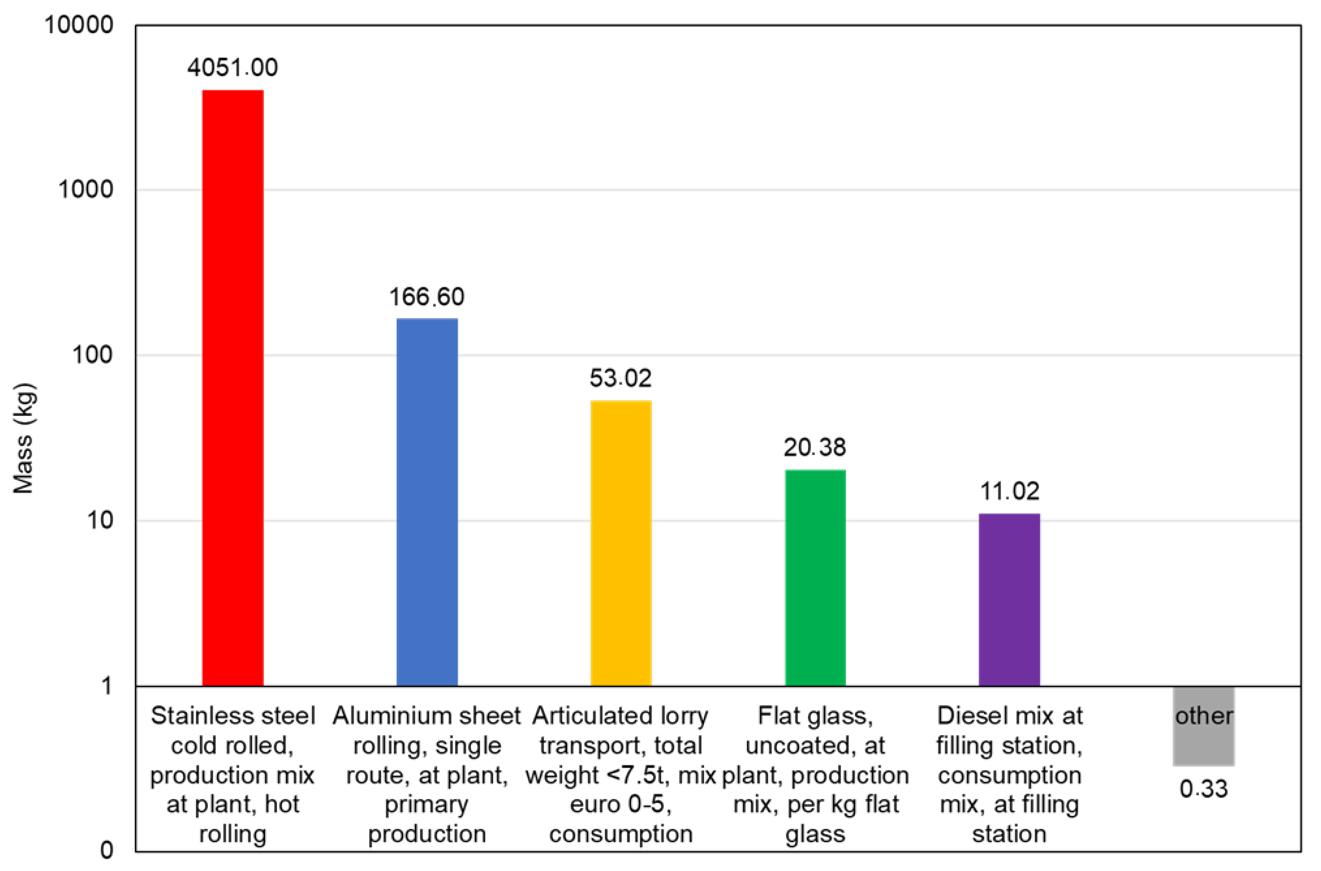
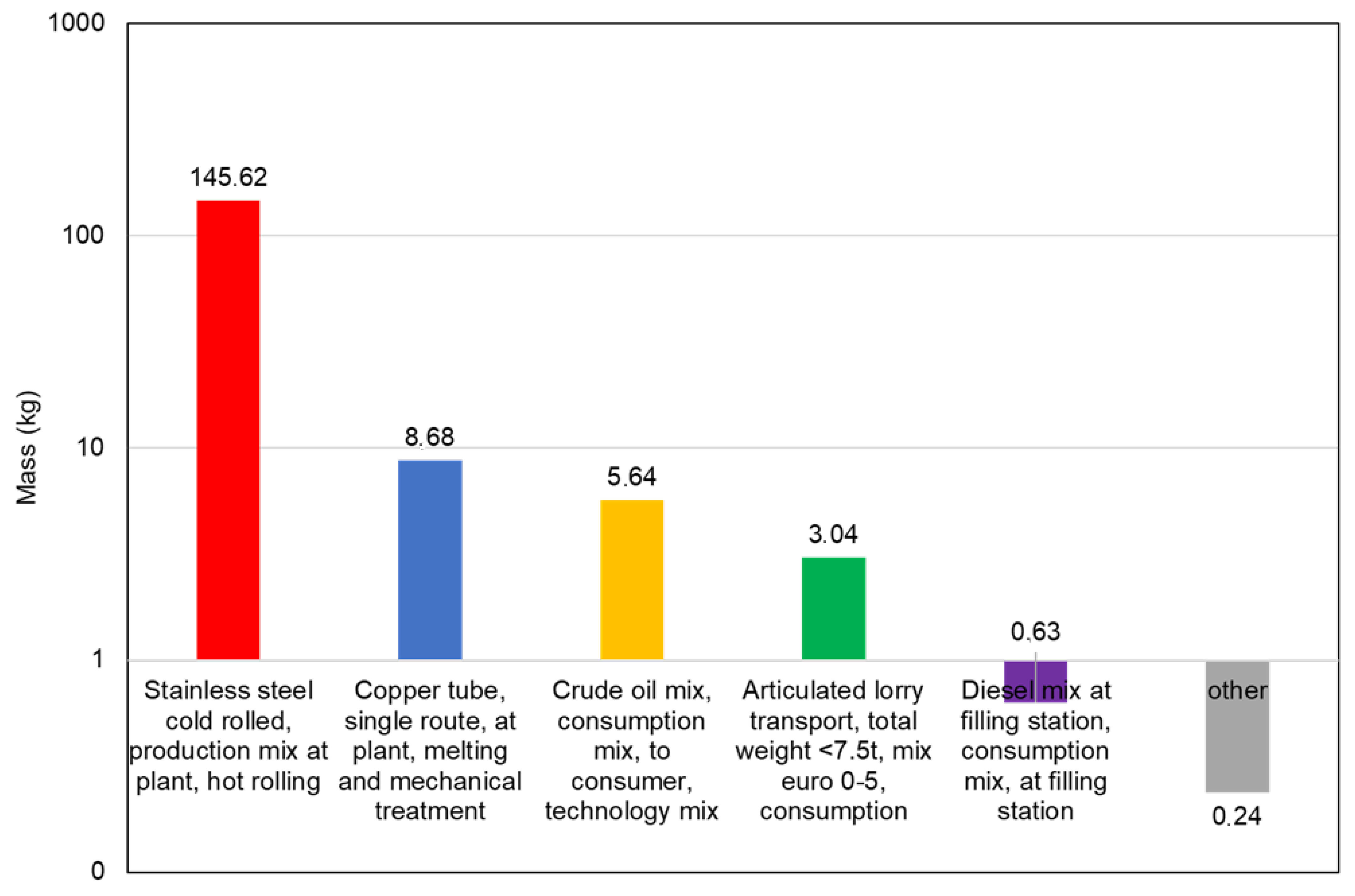
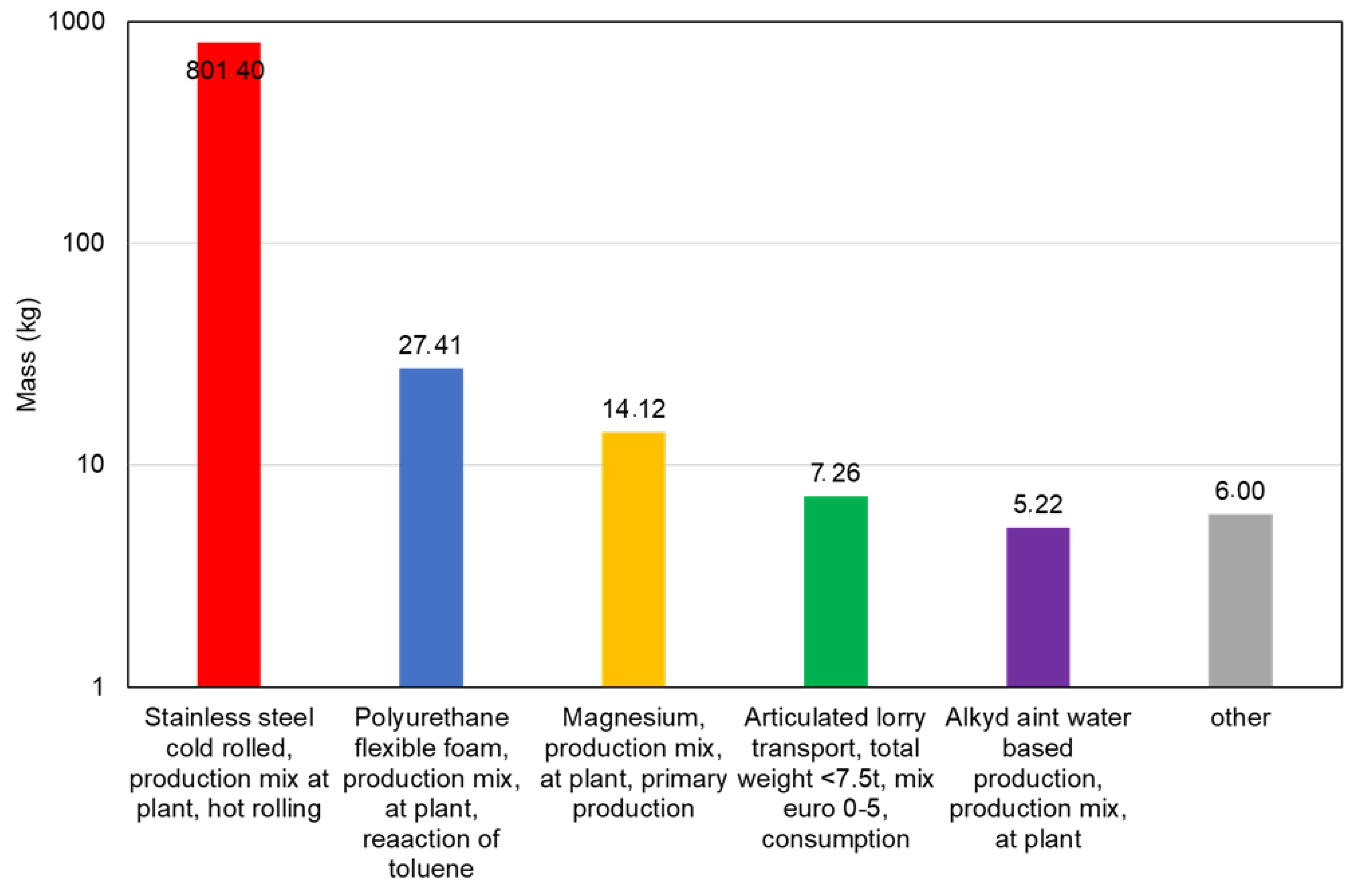
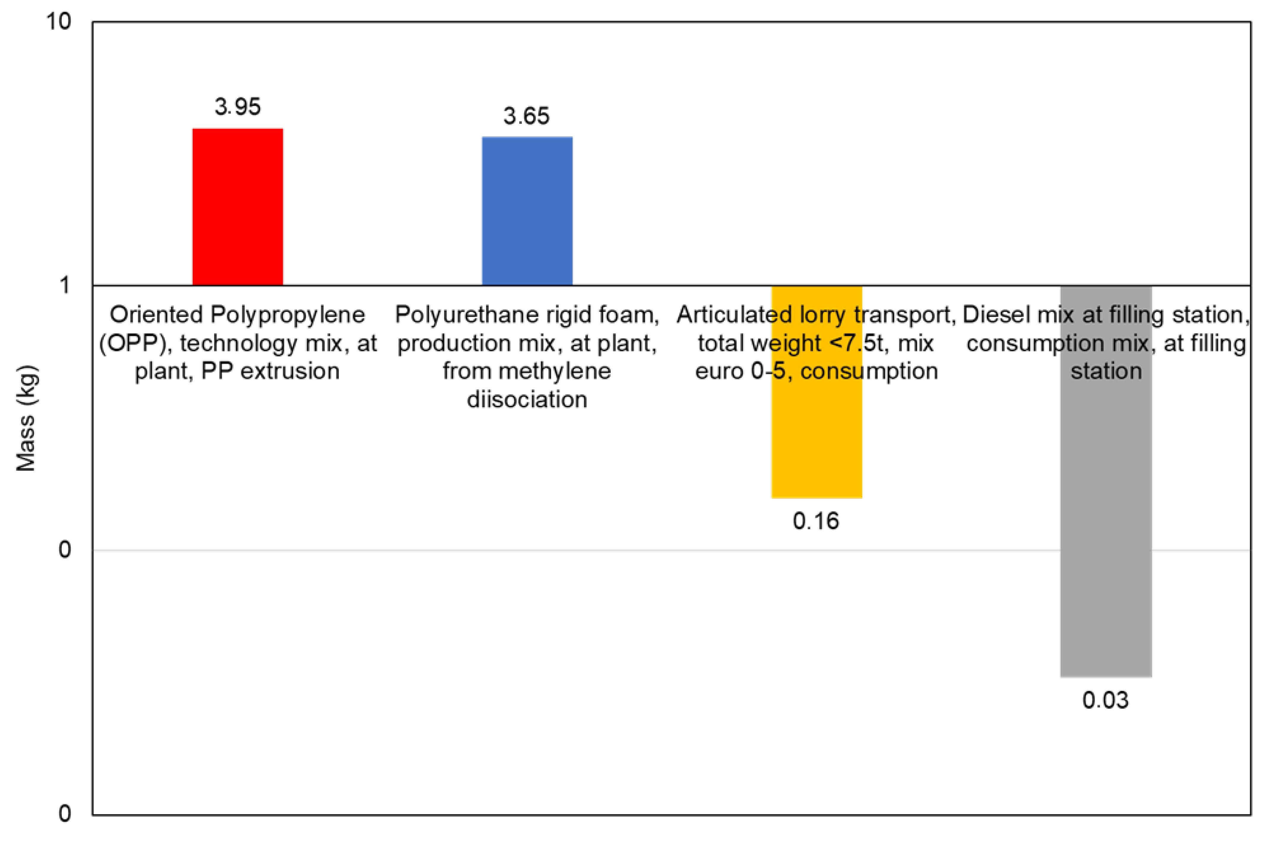
In all processes, except pipeline pipes, stainless steel production stands out as the most significant contributor to the climate change impact category. For both steel production technologies, hot-rolling and cold-rolling, the available data set includes all relevant stages of supply, with the process inventory based mainly on industrial data. The data set for steel production is based on internationally recognised production processes and linked to regional precursors. Although steel production is known for its energy intensity and significant greenhouse gas emissions, it is important to note that steel can be recycled. However, it should be noted that this analysis does not consider recycled steel as input material.
The process with the most significant impact in all categories, except for ozone depletion, is the manufacture of the dish, see
Table 10. Steel stands out as the least environmentally friendly material due to its energy-intensive production. This observation extends to other impact categories, and since satellite dishes contain a substantial amount of steel, they also emerge as the main contributors to these impact categories. In contrast, for the ozone depletion indicator, the pipe manufacturing process takes the lead. This contribution can be attributed to the use of polyurethane as an insulating material. The available data set for this material covers the entire life cycle and the inventory comes from European industry data (EU-28 + EFTA, (openLCA 1.10.3)). The same amount of domestic hot water could be heated with a conventional natural gas boiler. Assuming a boiler efficiency of 93% and stoichiometric methane consumption, 1.6 kg of CO
2 will be emitted in one day. Assuming the same emissions for 30 years and considering the same number of days of operation of the solar dish, 12,240 kg of CO
2 is emitted. This number results only from the operation phase of the system and is much larger than the number obtained from the production process of the four components of the solar dish analysed above. Assuming the same emissions over the life cycle and considering the days when the solar antenna is in operation, 12,240 kg CO
2 is emitted. This number comes only from the operation phase of the system and is much larger than that obtained from the production process of the four solar antenna components analysed above.


