Abstract
Today, impingement cooling structures with dimples can effectively ease the burden of turbine blades. This paper investigates the effect of dimple diameter and depth on the heat transfer of the target surface on a laminar-cooled turbine blade with a cross-flow and dimple numerically to find the mechanism behind it so that the dimple can be better used in turbine cooling. The commercial software ANSYS 19.2 and a baseline (BSL) turbulence model is used during the numerical computation. In this paper, the cross-flow Reynolds number varies from 15,000 to 60,000, while the jet Reynolds number remains at 30,000. When the cross-flow Reynolds number changes, due to the location change in vortexes generated inside or around the dimple, the two dimple parameters affect heat transfer differently. When the cross-flow Reynolds number is lower than the jet Reynolds number, dimples with smaller diameters and depths lead to better heat transfer performance. When the cross-flow Reynolds number exceeds the jet Reynolds number, dimples with bigger diameters and depths result in better heat exchange performance. The results also indicate that, while the dimple diameters remain constant, the rise of the cross-flow Reynolds number enhances the heat transfer of the dimple structure.
1. Introduction
As the temperature in aero-engines after burning continues to increase, turbine blades need advanced cooling methods to ease the thermal load [1]. Today, many researchers have studied transpiration, impingement and film cooling so that they can be better used in the field of turbine leading edge cooling. The studies cover the application on a single blade [2,3], the application on multiple blades [4], the mechanism [5,6] and the design of new structures [7]. The methods mentioned above effectively lower the thermal load of the turbine blade. Apart from that, structures that can enhance heat transfer are also set in turbine blades to further lower the temperature. Among the structures mentioned above, the pin fin, rib and dimple attract many researchers’ attention. The combinations of the structures are also studied to find a better way to enhance the local heat transfer [8,9]. Studies on relevant topics [10] have also acknowledged the effectiveness of the structures.
Luo et al. [11] numerically studied the effect of pin fin parameters, such as arrangement, diameter and cross-section shape, on heat transfer. They found that the heat exchange is optimized while the pin fin parameters are fixed at certain values. Wu et al. [12] made numerical studies about the model of the turbine trailing edge with pin fins and revealed that the pin fin homogenized the coolant inside the turbine blade. Han [13] investigated the heat transfer of the channel with a rib. The complex rib produced better heat transfer performance. Lee et al. [14] focused on the heat exchange characteristic in an equilateral triangle channel set with ribs. The application of pin fins and ribs protects turbine blades from the high thermal load, but too many pin fins and ribs can cause a reduction in blade strength and work stability. Dimples, however, do not weaken the strength of the blade and are easy to process.
In the 1990s [15], aero-engine researchers introduced the concept of dimples. Since then, numerous fundamental studies have focused on dimples. Some showed that dimples can excite vortices to change the boundary layer thickness and improve local heat transfer performance [16,17,18]. There are also studies [16] that apply the dimple to the turbine blade to cool down a certain area.
Kanokjaruvijit and Martinez [19] investigated the heat exchange characteristic on a target wall with dimples and a jet. The results indicated that shallow dimples increased the heat transfer effect by 70% compared with a channel that has a smooth wall. Mohammad et al. [20] studied the heat transfer performance accuracy of dimpled tubes that had different cross-section shapes simulated by different turbulence models. The most accurate results are made by the nonlinear k-ε turbulence model, and these results are much better than those found using the latitudinal k-ε turbulence model and the linear k-ε turbulence model. Also, by using the linear k-ε turbulence model, the heat transfer performance inside the dimple is optimized. Luo et al. [21] studied the performance of a solar receiver with dimples and DWVG using the NSGA-II optimization algorithm and CFD calculations. The results revealed that the arrangement of dimples affected the heat transfer performance of the target surface. Kim et al. [22] made a numerical analysis of dimple arrangement and found that dimples in a staggered arrangement had better heat transfer performance than dimples in an in-line arrangement.
The jet generated cross-flow after impacting the dimpled target surface. The cross-flow influences the jet downstream significantly. Some researchers have studied the impact of cross-flows.
Zhang C. et al. [23] conducted studies on the influence of cross-flows on heat transfer inside the impingement cooling structure. The results revealed that the cross-flow increased the Nusselt number of the area where the jet hit the wall, so the local heat transfer performance was improved. Florschuetz and Su [24] studied the influence of a cross-flow on a jet and revealed that the cross-flow changed the flow direction of the jet and enhanced the heat transfer. Moreover, a certain velocity ratio of cross-flow and jet leads to the highest Nusselt number and the best heat transfer effect. Tan L. et al. [25] conducted an investigation on the heat transfer performance of impingement cooling under cross-flow via computation. The results explained the mechanism by which the jet-to-surface spacing and the arrangement of the holes affected the heat transfer performance. Their results revealed that the rise of the jet-to-surface spacing enhanced the heat exchange effect of the area between the jet hole and the film hole. When the Reynolds number ratio of jet and cross-flow is less than or equal to 0.5, the cross-flow worsened the local heat exchange performance. Wang et al. [26] set up vortex generators upstream of the jet outlet under cross-flow and measured the heat transfer performance of the target surface. Their experimental results showed that the vortex generator enhanced heat transfer and the increase in the cross-flow Reynolds number. Lee et al. [27] experimentally investigated the influence of cross-flow on the Nusselt number under various jet-to-surface spacing and jet hole spacing conditions with the cross-flow Reynolds number equal to 8000. For a dense array of dimples (hole spacing of five times or eight times the jet hole diameter.), the cross-flow is not conducive to a uniform local Nusselt number distribution. The studies mentioned above mainly focus on the flow and heat transfer of dimpled plates with a cross-flow and dimple arrangement. The results indicate that dimple parameters influence the flow and heat exchange of the target surface. However, the mechanisms by which dimple parameters affect flow and heat transfer performance on the target surface are less concerning but must still be studied. In this paper, the effect of two structural parameters of dimples (diameter and depth) on the heat transfer of a laminar-cooled turbine blade with a cross-flow and dimple is investigated. Numerical computation is used to analyze the heat transfer performance on the target surface. Preliminary conclusions are drawn from the analysis.
2. Research Method and Scheme Design
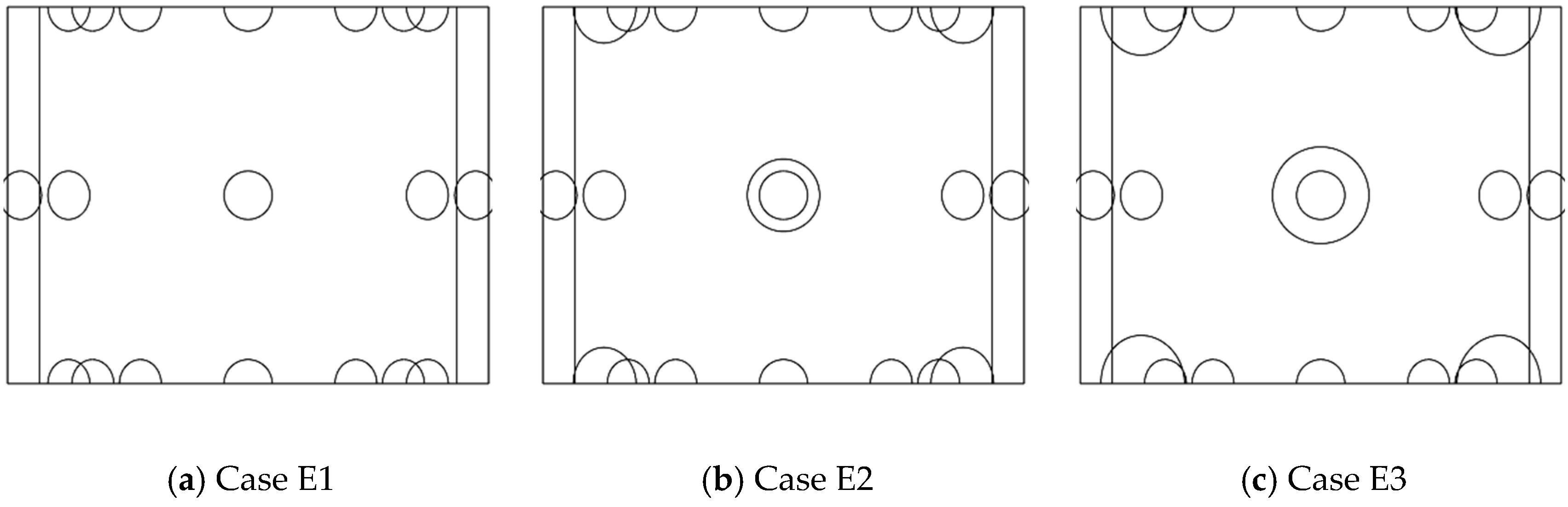
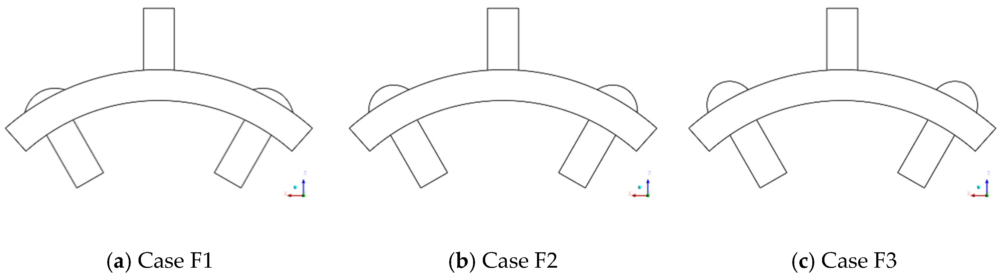
2.1. Geometry Model
Figure 1 shows the physical model of the fluid domain for numerical computation. The width of the target surface is . The arc length of the target surface is . The length of the jet hole is . The length of the film hole is . The regularized curvature is , in which is the radius of curvature on the target surface, and is the target surface chord length. The distance between the jet inlet and the target surface is .
Figure 1.
Geometry model.
The three structures used to study the effect of dimple diameter on heat transfer performance at the target surface are presented in Figure 2. The dimensionless depth of the dimple is and holds constant, while the dimensionless diameter of the dimple () varies. By changing the cross-flow Reynolds number in each structure, twelve cases are set in the study. The structures of Cases E12, E13, E14 and E15 compose Case E1. The structures of Cases E22, E23, E24 and E25 compose Case E2. The structures of Cases E32, E33, E34 and E35 compose Case E3. Table 1 shows the related parameters in the twelve cases.
Figure 2.
Structural diagram of the target surface with different dimple diameters.
Table 1.
The parameters of cases with different dimple diameters and cross-flow Reynolds numbers.
The three structures used to find the influence of dimple depth on the heat transfer of the target surface are displayed in Figure 3. The dimensionless diameter of the dimple is and remains unchanged, while the dimensionless depth of the dimple () varies. By changing the cross-flow Reynolds number in each structure, twelve cases are set during the study. Table 2 shows the related parameters in the twelve cases.
Figure 3.
Structural diagram of the target surface with different dimple depths.
Table 2.
The parameters of cases with different dimple depths and cross-flow Reynolds numbers.
2.2. Parameters Definition
The dimensionless depth of the dimple is defined as
where stands for dimple depth, and stands for dimple diameter.
The dimensionless diameter of the dimple is defined as
where stands for dimple diameter and stands for jet hole diameter.
The jet Reynolds number is defined as
where stands for impact jet velocity, stands for jet motion viscosity, and stands for jet hole diameter.
The cross-flow Reynolds number is defined as
where stands for cross-flow velocity, stands for cross-flow motion viscosity, and stands for jet-to-surface spacing.
The target surface Nusselt number is defined as
where stands for the fluid convection heat transfer coefficient, stands for the width of the target surface, and stands for fluid thermal conductivity.
2.3. Boundary Conditions
Figure 1 exhibits the boundary condition of the model in the computational calculation. The fluid is set as the ideal gas during the whole simulation. The model has two inlets: jet hole inlet and cross-flow inlet. The rate of inlet flow is fixed, and the total temperature of the two inlets is . The turbulence intensity of inlets is . The jet hole inlet Reynolds number defined by is 30,000 and holds constant. The cross-flow inlet Reynolds numbers defined by are set to 15,000, 30,000, 45,000 and 60,000. The model also has two outlets: a film hole outlet and a cross-flow outlet. The static pressure of two outlets is fixed at .
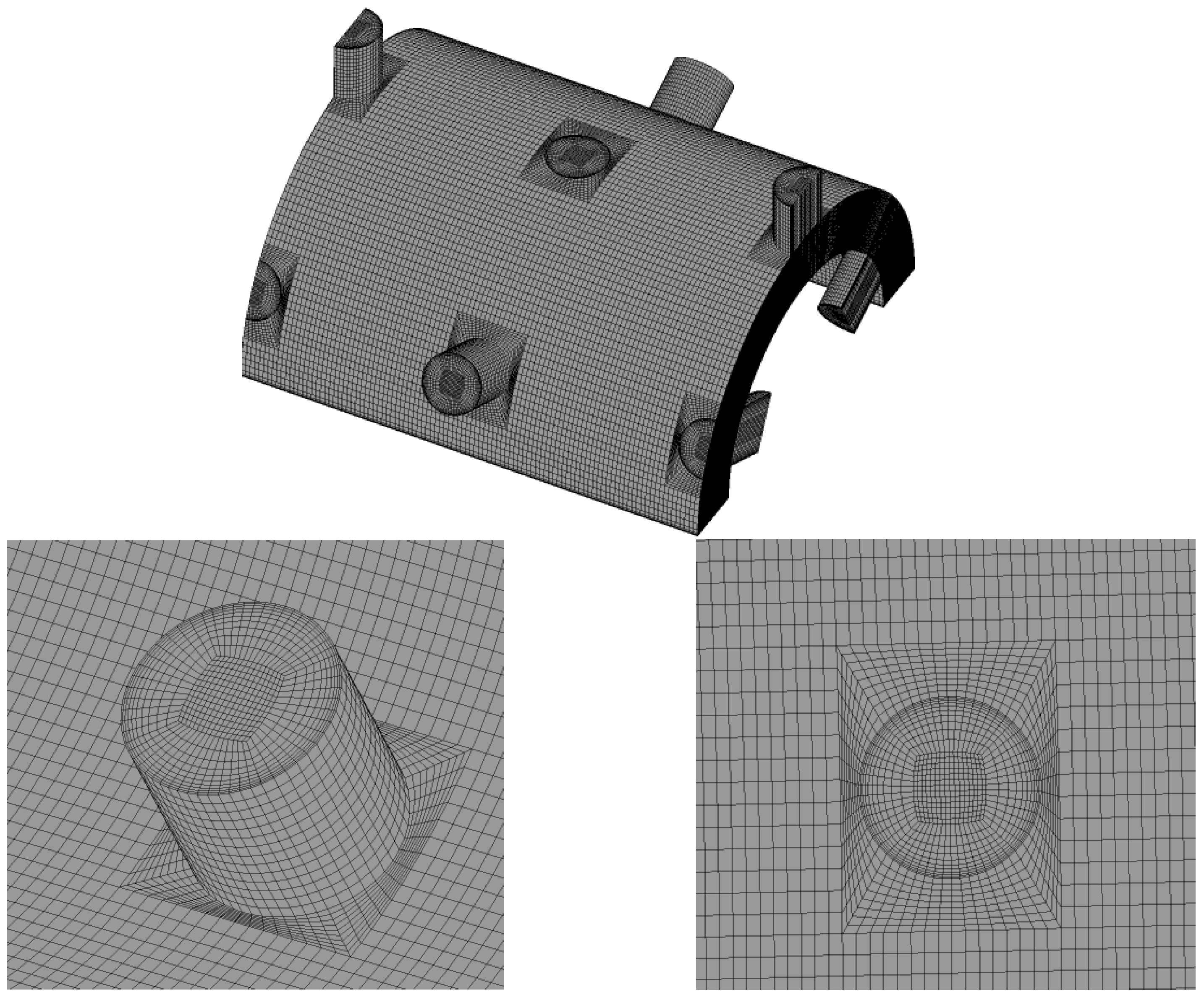
2.4. Mesh Generation
Figure 4 shows the meshed image of the computational domain. The mesh is produced by in-house code that has high accuracy and efficiency for the mesh generation of complex structures. A more detailed description of this method is given in another paper [28].
Figure 4.
Meshed image of the computational domain.
The generated mesh quality is assessed by the ICEM module of ANSYS software. The results show that the mesh quality is above 0.4. value is less than 1. The thickness of the first layer is .
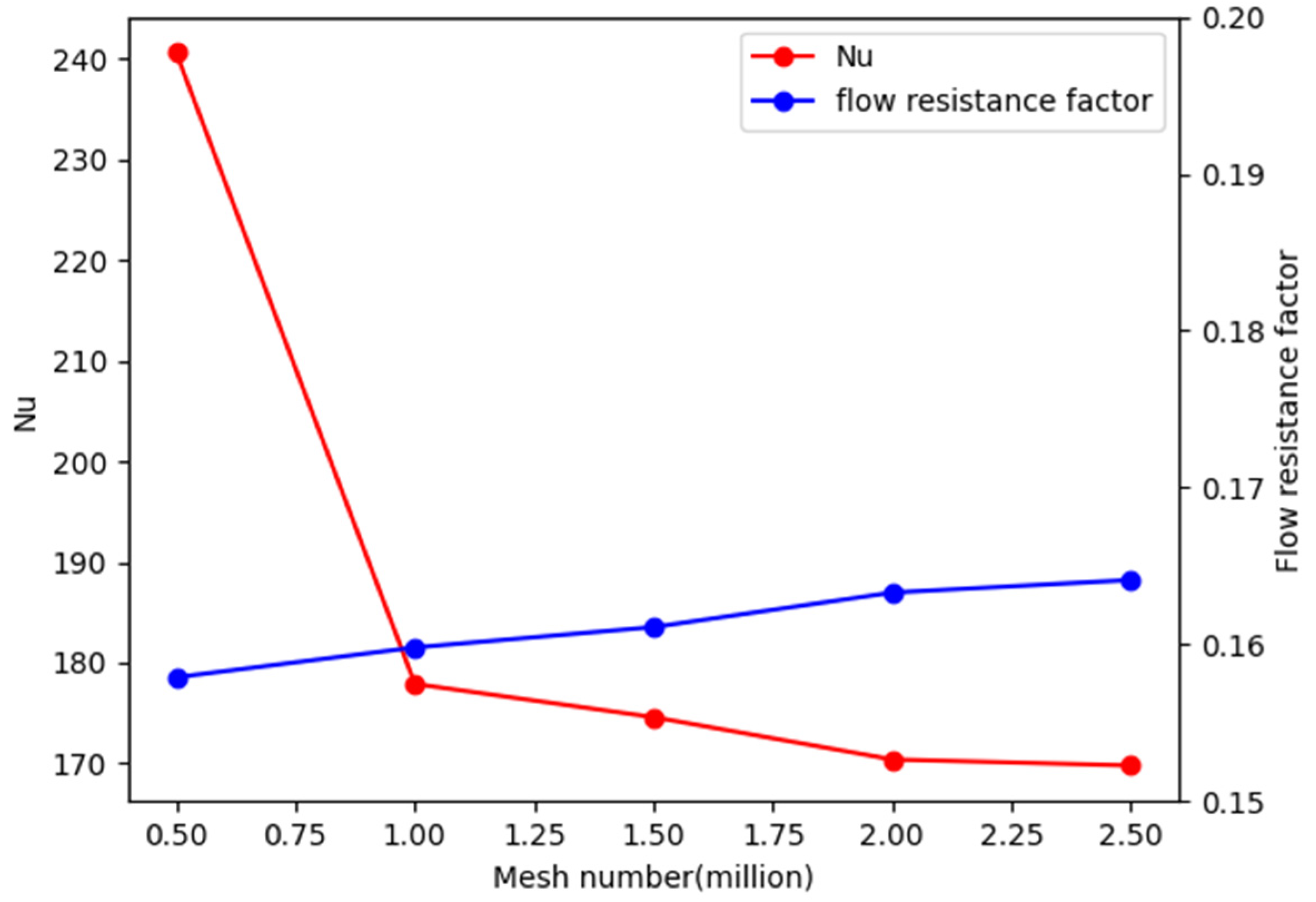
2.5. Grid Independency Test
Mesh independence check is carried out to test the accuracy of the numerical computation. The Reynolds-averaged Navier–Stokes (RANS) method is used in all cases. The governing equations are expressed in Equations (6)–(9). Baseline (BSL) turbulence model [29] is chosen in the computation because the model is widely used in aerodynamic studies and has been proven to have good accuracy. The equations of the turbulence model are given in Equations (10) and (11). The time step is set as “Local Timescale Factor”, and the simulation is stopped manually as the residual error is lower than 0.0001.
The Nusselt number of the target surface and the flow resistance factor in the mesh-independent validation are shown in Figure 5. It can be seen that the flow resistance factor changes slightly as the number of meshes increases from 0.5 million to 2.5 million. The Nusselt number of the target surface varies slightly as the mesh number grows over 2.0 million. Considering the calculation volume, 2 million meshes are ideal.
Figure 5.
Mesh independence check.
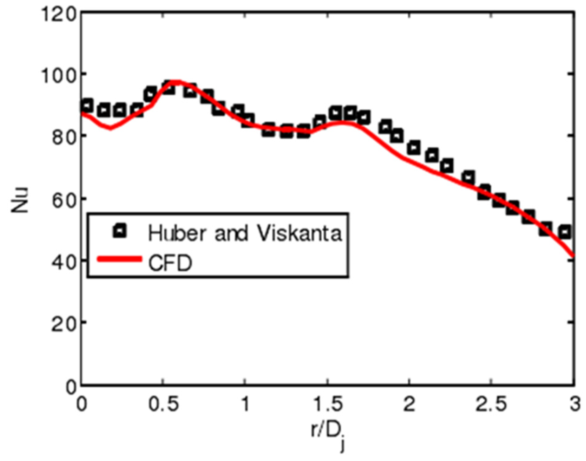
2.6. Numerical Validation
To prove the reliability of the numerical computation, numerical validation is carried out based on the experimental results from Funazaki et al. [30] because the physical models are similar. Figure 6 exhibits the contrast of the heat transfer coefficient cloud chart between numerical and experimental data. The regions marked in capital letters and corresponding small letters shows the same area in numerical and experimental results so that the results are easier to be compared. The results are found to be in good agreement in the area of jet stagnation (Region A and Region a) and the leading edge of the pin fin (Region D and Region d) by comparing the computation method with the experimentally measured heat transfer coefficients.
Figure 6.
The heat transfer coefficient cloud chart of numerical and experimental data.
The physical model used in this paper has no pin fin. To testify the applicability of CDF for the object of study, another numerical validation is based on the experimental results of Huber and Viskanta [31]. The result is shown in Figure 7. The numerical results agree well with the experimental results as the dimensionless diameter varies from 0.5 to 1.5 and from 2.5 to 3. When the dimensionless diameter is lower than 0.5 or ranges between 1.5 to 2.5, the relative error of the Nusselt number is less than 5%. Therefore, the numerical simulation is valid.
Figure 7.
The Nusselt number chart of computation and experiment.
3. Analysis of Calculated Results
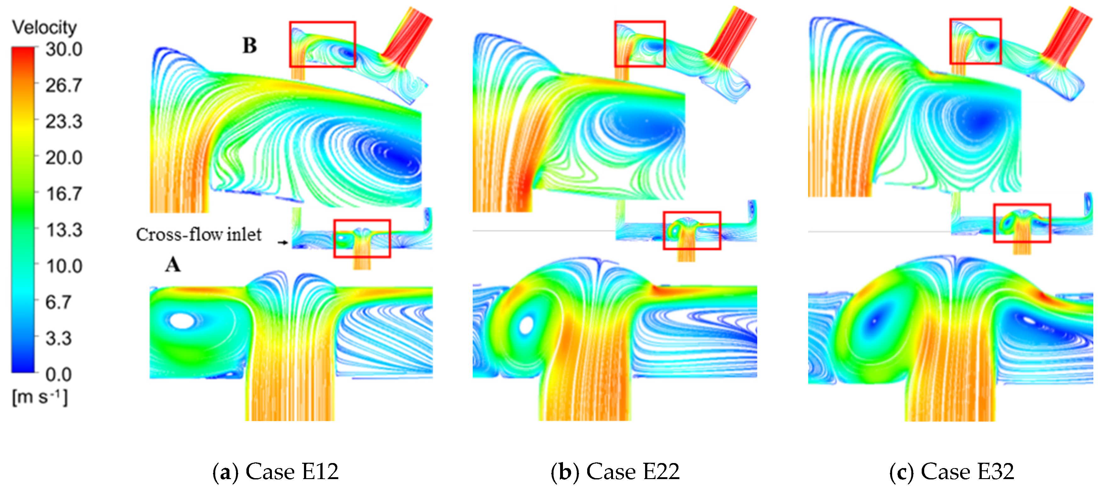
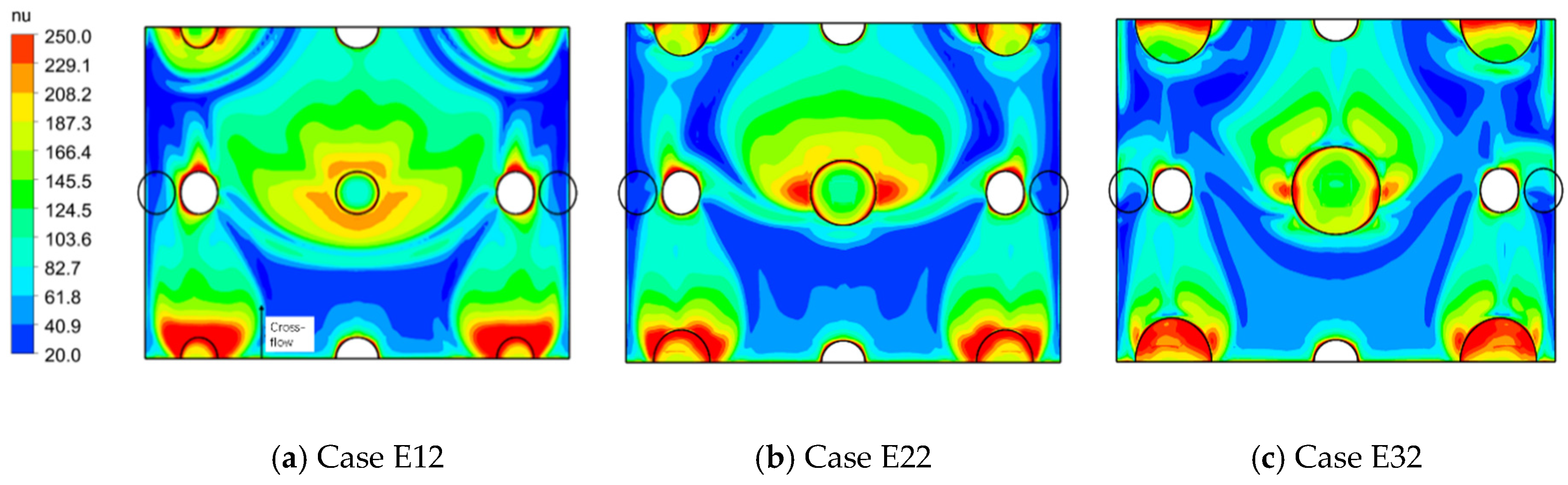
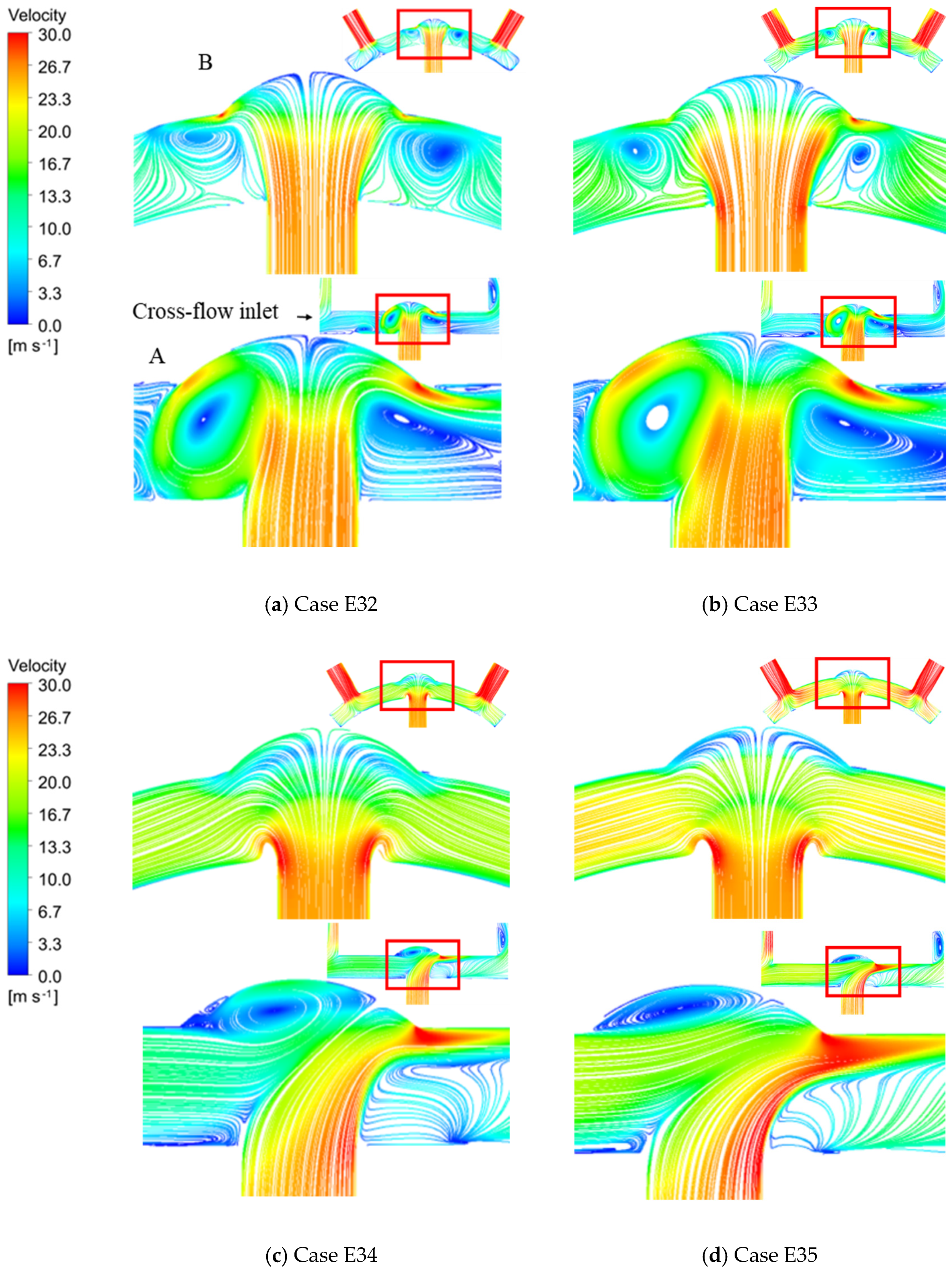
3.1. The Influence of Dimple Diameter on Heat Transfer at Target Surface under Cross-Flow
3.1.1. Flow Field and Heat Transfer
During the numerical computation, the situations in which and are discussed separately. Figure 8 shows the streamline plot in cases with different dimple diameters at a fixed cross-flow Reynolds number, . In the figure, streamlines on different crossing-sections marked as “A” and “B” are shown. In each subgraph, the bottom left figure is an enlarged view of the part in the red frame. On this condition, . By comparing the streamline on cross-section A, it is found that the turning angle of the jet after impacting the target surface increases as the dimensionless dimple diameter grows. Also, as the dimple diameter increases, a vortex that is close to the dimple wall is formed. Due to the joint action of the vortex and jet, the flow velocity at the dimple edge increases, leading to a thin boundary layer and high turbulent kinetic energy. Thus, the heat transfer effect at the dimple edge is enhanced in cases with larger dimple diameters. The flow velocity outside the dimple, however, decreases, so the heat transfer performance is weakened. The above phenomena also occur in cross-section B. The heat transfer outside the dimple in Case E12 is better than in the other cases. The vortex formed in the chamber is far away from the dimple in Case E12, so the jet develops well near the target surface and the high-speed area is large. In Case E22 and Case E32, however, the vortex in the chamber is close to the dimple and target surface. The vortex affects the development of the jet, so the heat transfer is weakened.
Figure 8.
Streamline in cases with different dimple diameters when .
Figure 9 exhibits the Nusselt number distribution in cases with different dimensionless dimple diameters and the same cross-flow Reynolds number, . As the dimensionless dimple diameter grows, the high Nusselt number area at the dimple edge shrinks. In Case E12, the Nusselt number at the area around the dimple is higher than in other areas, and the low Nusselt number area around the dimple is small in Case E12.
Figure 9.
distribution in cases with different dimple diameters when .
As for the situations in which , the streamline plot of cases with different dimensionless dimple diameters at the fixed value of is illustrated in Figure 10. In the figure, streamlines on different crossing-sections marked as “A” and “B” are shown. In each subgraph, the bottom left figure is an enlarged view of the part in the red frame. The vortex generated inside the dimple gradually moves away from the wall as the dimensionless dimple diameter grows, increasing flow velocity near the wall, which can be found on both cross-sections A and B (same definition as in Figure 8). Therefore, in cases with a larger dimensionless dimple diameter, the boundary layer inside the dimple is thinner. In summary, larger dimensionless dimple diameter results in better heat transfer performance.
Figure 10.
Streamline in cases with different dimple diameters when .
3.1.2. The Influence of
To study the influence of the , Figure 11 illustrates the streamline in Case E3 (cases in which the dimensionless dimple diameter is 2.0) under a different . In the figure, streamlines on different crossing-sections marked as “A” and “B” are shown. In each subgraph, the bottom left figure is an enlarged view of the part in the red frame. Considering the streamline on cross-section A, part of the jet, after impacting the target surface, flows in the opposite direction of the cross-flow and forms a vortex. When the increases, the vortex gradually moves inside the dimple and thickens the boundary layer, which causes weak heat transfer. The other part of the jet, after impacting the target surface, however, flows in the same direction of the cross-flow. As the grows, the flow velocity of this part of the jet increases, leading to a thin boundary layer and enhanced heat transfer performance. On cross-section B, with the increase in the , the vortex outside the dimple disappears, which is favorable for heat transfer. Combining the streamline plot on cross-sections A and B, the heat transfer at part of the dimple is enhanced with the rise in the .
Figure 11.
Details of the flow field in Case E3 under different s.
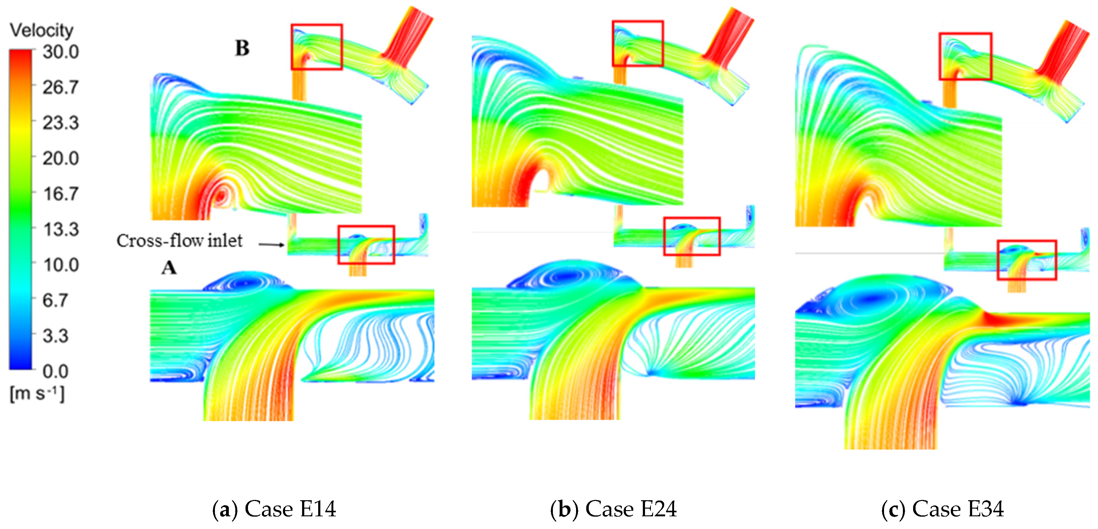
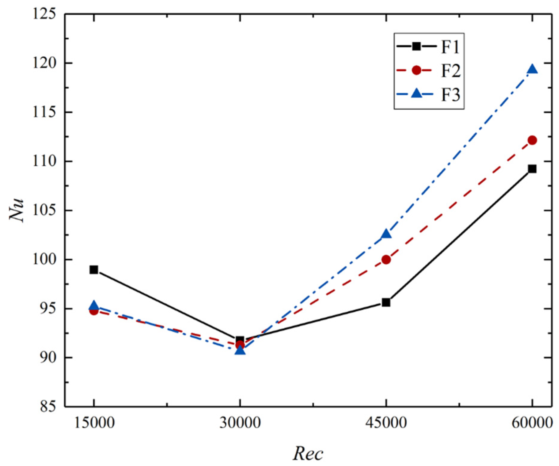
3.2. The Influence of Dimple Depth on Heat Transfer at Target Surface under Cross-Flow
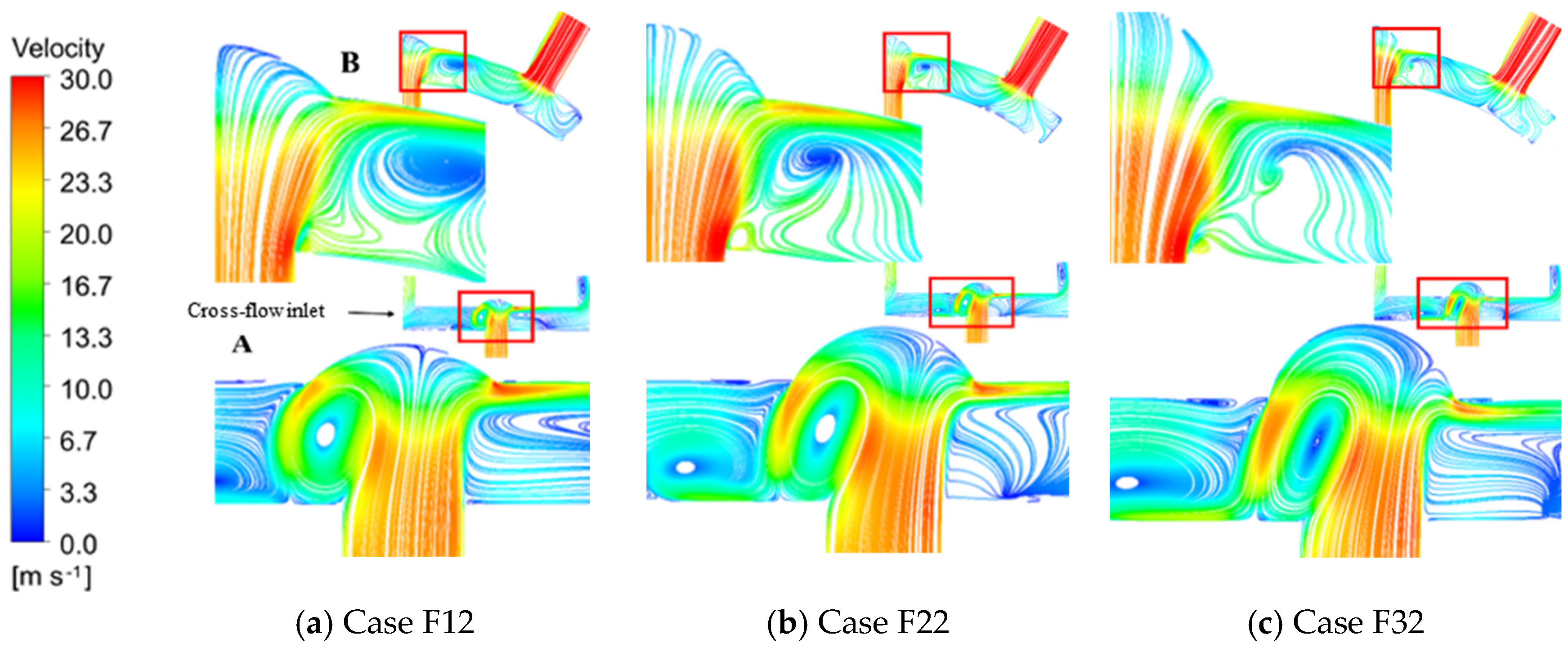
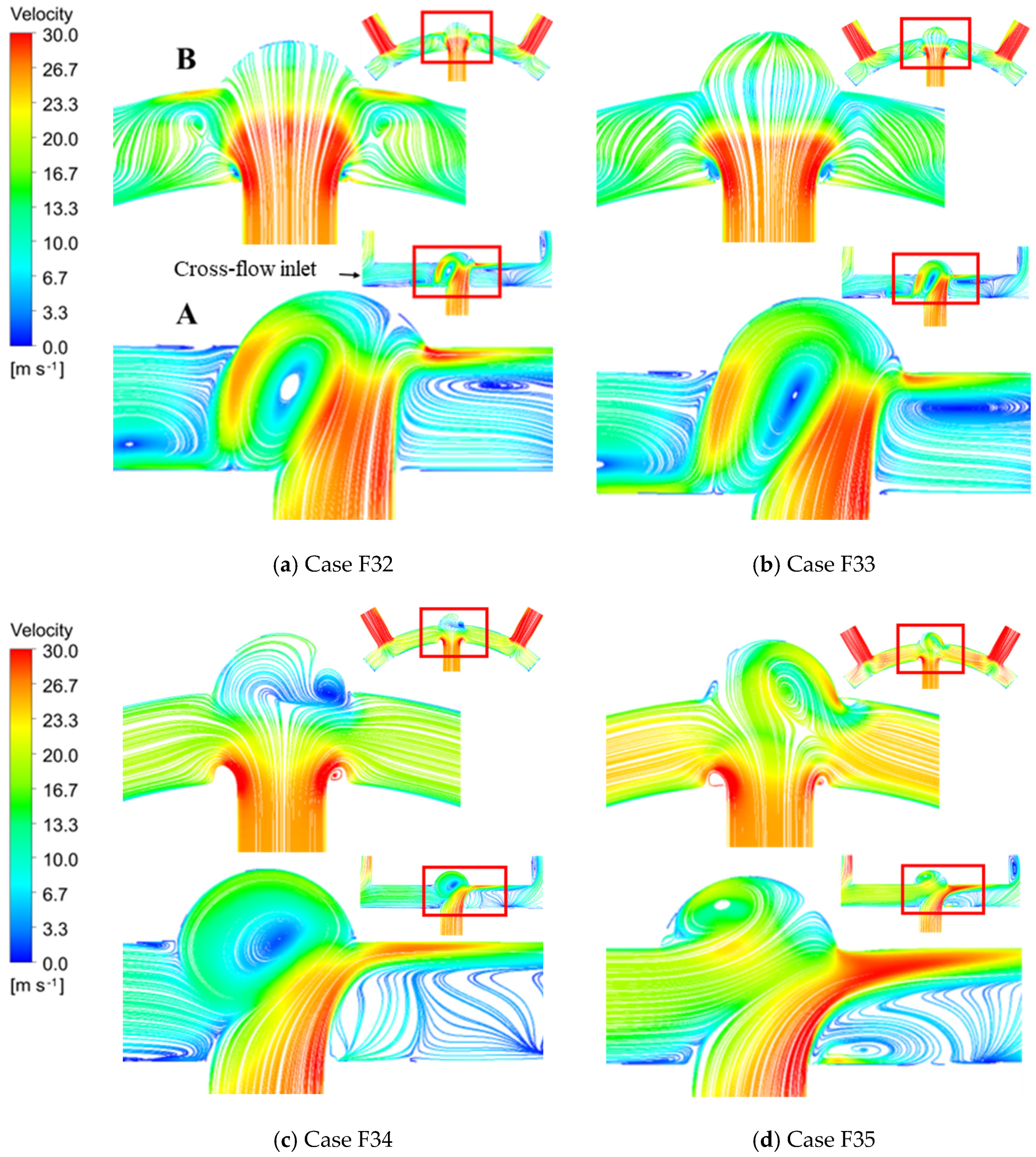
3.2.1. Flow Field and Heat Transfer
Figure 12 plots the Nusselt number curves as the increases from 15,000 to 60,000. In the process of the increasing from to , the average Nusselt number in all three cases decreases. If the continues to increase, the average Nusselt number in all three cases increases, and cases with larger dimensionless dimple depth have larger variation. When , Case F1 has the highest average Nusselt number, and the average Nusselt numbers in Case F2 and Case F3 are nearly the same. The decrease in dimple depth makes the Nusselt number increase by 3%. When , the average Nusselt numbers in all three cases are similar to each other. When or , Case F3 has the highest average Nusselt number, and Case F1 has the lowest. The increase in dimple depth causes an increase of 10% in the Nusselt number.
Figure 12.
Folding line chart of in different cases when increases from to .
During the numerical computation, the situations in which and are discussed separately. Figure 13 shows the streamline plot of cases with different dimensionless dimple depths at a fixed cross-flow Reynolds number, . In the figure, streamlines on different crossing-sections marked as “A” and “B” are shown. In each subgraph, the bottom left figure is an enlarged view of the part in the red frame. As can be seen on cross-section A, the impact center of the jet shifts to the cross-flow downstream, and the flow velocity near the dimple wall decreases as the dimensionless dimple depth increasing. Part of the jet forms a vortex after mixing with the cross-flow. The vortex is far from the target surface, and the high-speed fluid flows away from the target surface. Therefore, this part of the jet does not contribute to the heat exchange performance on the target surface. The other part of the jet, however, improves the heat transfer on the target surface because the high-speed fluid is close to the target surface. As the dimensionless dimple depth rises, the high flow velocity area shrinks, so the heat exchange performance at the dimple edge is weakened. Considering cross-section B, it can be seen that, as the dimensionless dimple depth rises, the vortex scale decreases, and the vortex gradually moves towards the target surface, which slows down the fluid at the dimple edge. Therefore, the heat transfer performance becomes worse.
Figure 13.
Streamline in cases with different dimple depths when .
The results of the situation in which are discussed below. The streamline in three cases with different dimensionless dimple depths with is presented in Figure 14. In the figure, streamlines on different crossing-sections marked as “A” and “B” are shown. In each subgraph, the bottom left figure is an enlarged view of the part in the red frame. As the dimensionless dimple depth increases, the vortex formed by the joint action of the jet and cross-flow gradually moves away from the dimple wall, which can be concluded from the streamline in cross-section A. Therefore, the negative influence of the vortex on heat exchange near the target surface is reduced. In the peripheral area of the dimple downstream of the cross-flow, the fluid flows faster in cases with higher dimensionless dimple depth and covers a larger area. The flow field in the dimple is not symmetrical on cross-section B. The jet stagnation point shifts to the right. In Case F34, a vortex appears at the dimple edge. The flow velocity of the vortex is lower than the mainstream, but the overall flow velocity inside the dimple is high. Thus, the heat exchange inside the dimple is stronger than in the other two cases. Therefore, the heat transfer effect is better in cases with larger dimensionless dimple depth.
Figure 14.
Streamline in cases with different dimple depths when .
3.2.2. The Influence of
Figure 15 shows the streamline in Case F3 (cases in which the dimensionless dimple depth is 0.4) under different s. In the figure, streamlines on different crossing-sections marked as “A” and “B” are shown. In each subgraph, the bottom left figure is an enlarged view of the part in the red frame. According to the streamline on cross-section A, part of the jet, after impacting the wall, flows towards the incoming direction of the cross-flow, which forms a vortex. With the varying from (Case F32) to (Case F33), the vortex intensity increases, and the flow velocity of fluid near the dimple wall becomes higher. Thus, the heat transfer performance is better. However, the flow at the dimple edge in the downstream direction of the cross-flow slows down. The high flow velocity area shrinks, so the heat transfer is weakened. As continues to increase and exceeds , the average flow velocity in the chamber increases. The vortex scale inside the dimple decreases. Considering the streamline on cross-section A, it is found that part of the jet flows in the same way as the cross-flow develops close to the wall after impacting the target surface. As the increases, the flow velocity of this part of the jet increases, and the high-speed area expands. Therefore, in the area downstream of the cross-flow outside the dimple, the boundary layer is thin, and the heat transfer is enhanced. To sum up, the increase in the cross-flow Reynolds number enhances the heat exchange inside the dimple.
Figure 15.
Streamline in Case F3 under different s.
4. Conclusions
In this paper, the influence of dimple diameter and dimple depth on the heat exchange of the target wall of a laminar-cooled turbine blade with a cross-flow and dimple are studied separately.
The dimensionless dimple diameters are set as 1.0, 1.5 and 2.0. When the Reynolds number ratio of cross-flow and jet is lower than 1, the vortex generated outside the dimple gradually moves inside the dimple as the dimple diameter grows, which causes a thick boundary layer at the wall. So, a small dimple diameter is ideal. When the Reynolds number ratio of cross-flow and jet exceeds 1, while the dimple diameter increases, the vortex formed inside the dimple deserts the wall. The movement of the vortex enhances the local heat exchange. A large dimple diameter leads to a large area of enhanced heat transfer.
The dimensionless dimple depths are set as 0.2, 0.3 and 0.4. While the cross-flow Reynolds number rises, the Nusselt number of dimpled surfaces in all cases decreases first and then increases. When the Reynolds number ratio of cross-flow and jet is lower than 1, the vortex formed outside the dimple gradually moves towards the wall as the dimple becomes deeper, which makes the boundary layer thicker. Shallower dimples were able to increase the Nusselt number by up to 3% in this study. When the Reynolds number ratio of cross-flow and jet is higher than 1, as the dimple becomes deeper, the vortex gradually deserts the wall and the average velocity inside the chamber increases. Thus, deeper dimples were able to increase the Nusselt number by up to 10% in this study.
Author Contributions
Conceptualization, Y.S. and L.L.; methodology, B.Q. and Z.C.; software, D.H. and F.Z.; validation, D.H.; formal analysis, Y.S. and Y.O.; writing—original draft preparation, B.Q.; writing—review and editing, Z.C.; visualization, F.Z. and Y.S. All authors have read and agreed to the published version of the manuscript.
Funding
The authors acknowledge the financial support provided by the Natural Science Fund for Excellent Young Scholars of Heilongjiang Province (No. YQ2021E023) and the National Science and Technology Major Project (No. 2019-II-0010-0030).
Institutional Review Board Statement
Not applicable.
Informed Consent Statement
Not applicable.
Data Availability Statement
Not applicable.
Conflicts of Interest
The authors declare no conflict of interest.
Nomenclature
| List of symbols and abbreviations | |
| Dimple depth | |
| Dimple diameter | |
| Jet hole diameter | |
| Jet Reynolds number | |
| Impact jet velocity | |
| Jet motion viscosity | |
| Cross-flow Reynolds number | |
| Cross-flow velocity | |
| Cross-flow motion viscosity | |
| Jet-to-space spacing | |
| Target surface Nusselt number | |
| Fluid convention heat transfer coefficient | |
| Width of target surface | |
| Fluid thermal conductivity | |
References
- Basir, H.; Alaviyoun, S.; Rosen, M.A. Thermal Investigation of a Turbocharger Using IR Thermography. Clean Technol. 2022, 4, 329–344. [Google Scholar] [CrossRef]
- Kim, M.; Dong, H.S.; Jin, S.K.; Lee, B.J.; Lee, J. Experimental investigation of effusion and transpiration air cooling for single turbine blade. J. Appl. Therm. Eng. 2021, 182, 116156. [Google Scholar] [CrossRef]
- Zhu, X.; Zhang, J.; Tan, X. Numerical assessment of round-to-slot film cooling performances on a turbine blade under engine representative conditions. J. Int. Commun. Heat Mass Transf. 2019, 100, 98–110. [Google Scholar] [CrossRef]
- Kumar, S.; Singh, O. Enhancement of combined cycle performance using transpiration cooling of gas turbine blades with steam. J. Mech. Sci. Technol. 2014, 28, 2429–2437. [Google Scholar] [CrossRef]
- He, J.; Luo, X.; Peng, Y. Investigation on the relation of transpiration cooling of sintered woven wire mesh and particle deposition. J. Gas Turbine Exp. Res. 2018, 31, 40–45. [Google Scholar]
- Goldstein, R.J.; Sobolik, K.A.; Seol, W.S. Effect of entrainment on the heat transfer to a heated circular air jet impinging on a flat surface. J. Heat Transf. 1990, 112, 608–611. [Google Scholar] [CrossRef]
- Martini, P.; Schulz, A.; Bauer, H.J. Film cooling effectiveness and heat transfer on the trailing edge cut-back of gas turbine airfoils with various internal cooling designs. J. Turbomach. 2014, 128, 87–96. [Google Scholar]
- Shen, Z.; Xie, Y.; Zhang, D. Numerical predictions on fluid flow and heat transfer in U-shaped channel with the combination of ribs, dimples and protrusions under rotational effects. J. Int. J. Heat Mass Transf. 2015, 80, 494–512. [Google Scholar] [CrossRef]
- Alaskari, M.; Kadhim, A.M.; Farhan, A.A.; Al-Damook, M.; Al Qubeissi, M. Performance Evaluation of Roughened Solar Air Heaters for Stretched Parameters. Clean Technol. 2022, 4, 555–569. [Google Scholar] [CrossRef]
- Luo, L.; Wang, C.; Wang, L.; Bengt, S.; Wang, S. Effects of pin fin configurations on heat transfer and friction factor in an improved lamilloy cooling structure. J. Heat Transf. Res. 2017, 48, 657–679. [Google Scholar] [CrossRef]
- Wu, W.; Xu, H.; Wang, J. Numerical investigation of pin-fin influences on cooling air flow characteristics in turbine blade trailing edge region. J. Propuls. Technol. 2021, 42, 163–172. [Google Scholar]
- Han, J.C. Heat transfer and friction in channels with two opposite rib-roughened walls. J. Heat Transf. 1984, 106, 774–781. [Google Scholar] [CrossRef]
- Lee, D.H.; Rhee, D.H.; Cho, H.H.; Moon, H.K. Heat transfer measurements in a rotating equilateral triangular channel with various rib arrangements. In Proceedings of the American Society of Mechanical Engineers Digital Collection, ASME Turbo Expo 2006: Power for Land, Sea, and Air, Barcelona, Spain, 8–11 May 2006. [Google Scholar]
- Afanasyev, V.N.; Chudnovsky, Y.P.; Leontiev, A.I.; Roganov, P.S. Turbulent flow friction and heat transfer characteristics for spherical cavities on a flat plate. J. Exp. Therm. Fluid Sci. 1993, 7, 1–8. [Google Scholar] [CrossRef]
- Rao, Y.; Xu, Y.; Wan, C. A numerical study of the flow and heat transfer in the pin fin-dimple channels with various dimple depths. J. Heat Transf. 2012, 134, 071902. [Google Scholar] [CrossRef]
- Lan, J.; Xie, Y.; Zhang, D. Heat transfer enhancement in a rectangular channel with the combination of ribs, dimples and protrusions. In Proceedings of the Turbo Expo: Power for Land, Sea, and Air, Barcelona, Spain, 8–11 May 2006. [Google Scholar]
- Murata, A.; Nishida, S.; Saito, H.; Iwamoto, K.; Okita, Y.; Nakamata, C. Heat transfer enhancement due to combination of dimples, protrusions, and ribs in narrow internal passage of gas turbine blade. In Proceedings of the Turbo Expo: Power for Land, Sea, and Air, Vancouver, BC, Canada, 6–10 June 2011. [Google Scholar]
- Xie, G.; Sundén, B.; Wang, Q. Predictions of enhanced heat transfer of an internal blade tip-wall with hemispherical dimples or protrusions. J. Turbomach. 2011, 133, 041005. [Google Scholar] [CrossRef]
- Kanokjaruvijit, K.; Martinez-Botas, R.F. Heat transfer and pressure investigation of dimple impingement. J. Turbomach. 2008, 130, 011003. [Google Scholar] [CrossRef]
- Fazli, M.; Raisee, M. Computation of flow and heat transfer through channels with periodic dimple/protrusion walls using low-Reynolds number turbulence models. Int. J. Numer. Methods Heat Fluid Flow 2019, 29, 1178–1207. [Google Scholar] [CrossRef]
- Luo, L.; Du, W.; Wang, S.; Wang, L.; Sundén, B.; Zhang, X. Multi-objective optimization of a solar receiver considering both the dimple/protrusion depth and delta-winglet vortex generators. J. Energy 2017, 137, 1–19. [Google Scholar] [CrossRef]
- Kim, S.M.; Kim, K.Y. Evaluation of cooling performance of impinging jet array over various dimpled surfaces. J. Heat Mass Transf. 2016, 52, 845–854. [Google Scholar] [CrossRef]
- Zhang, C.; Sun, J.; Li, H.; Mao, H. Investigation on heat transfer mechanism of impinging jet with cross-flow. J. Aerosp. Power 2011, 21, 528–532. [Google Scholar]
- Florschuetz, L.W.; Su, C.C. Effects of crossflow temperature on heat transfer within an array of impinging jets. J. Heat Transf. 1987, 109, 74–82. [Google Scholar] [CrossRef]
- Tan, L.; Zhang, J.; Tan, X. Numerical investigation of jet impingement cooling with non-uniform crossflow. J. Aerosp. Power 2006, 21, 528–532. [Google Scholar]
- Wang, C.; Luo, L.; Wang, L.; Sundén, B. Effects of vortex generators on the jet impingement heat transfer at different cross-flow Reynolds numbers. Int. J. Heat Mass Transf. 2016, 96, 278–286. [Google Scholar] [CrossRef]
- Lee, J.; Zhong, R.; Ligrani, P.; Lee, D.H.; Fox, M.D.; Moon, H.K. Cross-flow effects on impingement array heat transfer with varying jet-to-target plate distance and hole spacing. Int. J. Heat Mass Transf. 2014, 75, 534–544. [Google Scholar] [CrossRef]
- Luo, L. On the Design Method and Heat Transfer Mechanism of High Efficiency Cooling Structure in a Gas Turbine. Ph.D. Thesis, Harbin Institute of Technology, Harbin, China, 2016. [Google Scholar]
- Menter, F.R. Two-equation eddy-viscosity turbulence models for engineering applications. AIAA J. 1994, 32, 1598–1605. [Google Scholar] [CrossRef]
- Funazaki, K.; Tarukawa, Y.; Kudo, T.; Matsuno, S.; Imai, R.; Yamawaki, S. Heat transfer characteristics of an integrated cooling configuration for ultra-high temperature turbine blades: Experimental and numerical investigations. In Proceedings of the American Society of Mechanical Engineers Digital Collection, ASME Turbo Expo 2001: Power for Land, Sea, and Air, New Orleans, LA, USA, 4–7 June 2001. [Google Scholar]
- Huber, A.M.; Viskanta, R. Convective heat transfer to a confined impinging array of air jets with spent air exits. ASME J. Heat Transf. 1994, 116, 570–576. [Google Scholar] [CrossRef]
Disclaimer/Publisher’s Note: The statements, opinions and data contained in all publications are solely those of the individual author(s) and contributor(s) and not of MDPI and/or the editor(s). MDPI and/or the editor(s) disclaim responsibility for any injury to people or property resulting from any ideas, methods, instructions or products referred to in the content. |
© 2023 by the authors. Licensee MDPI, Basel, Switzerland. This article is an open access article distributed under the terms and conditions of the Creative Commons Attribution (CC BY) license (https://creativecommons.org/licenses/by/4.0/).