Article

Enhancement of Chiller Performance by Water Distribution on the Adiabatic Cooling Pad’s Mesh Surface

by
Anatolijs Borodinecs
,
Kristina Lebedeva
*,
Natalja Sidenko
and
Aleksejs Prozuments
Department of Heat Engineering and Technology, Riga Technical University, LV-1048 Riga, Latvia
*
Author to whom correspondence should be addressed.
Clean Technol. 2022, 4(3), 714-732; https://doi.org/10.3390/cleantechnol4030044
Submission received: 6 June 2022 / Revised: 19 July 2022 / Accepted: 22 July 2022 / Published: 26 July 2022

Abstract

:
Evaporative cooling is widely recognized as an energy efficient and environmentally-friendly air conditioning solution, and it has drawn a lot of market interest in recent years. However, this technology is accompanied by several challenges. For instance, insufficient evaporation due to poor and non-homogenous water distribution of the pre-cooling pad significantly reduces the cooling performance. The aim of the study is to develop a technique for numerical simulation of the distribution of a droplet liquid (water) on the mesh surface of an adiabatic cooler to improve the performance of air conditioning equipment. Modern computer-aided design (CAD)/computational fluid dynamics (CFD) programs were used to solve the issue. For the mathematical modelling of the medium motion, non-stationary Navier–Stokes equations were used. Parameters such as heat, mass transfer, and the efficiency of liquid droplet spraying were determined. The current study presents CAD modelling, conducted in SolidWorks platform, of water distribution on the adiabatic cooling pad’s mesh surface for improving air conditioning equipment performance. This study provides the methodology for computer modeling and numerical calculation of the parameters of adiabatic cooling, such as modelling of water atomization process. The results show that the use of additional metal mesh intended as cooling pads increases the mass transfer coefficient by Sh ≈ 15–40%; heat transfer coefficient Nu increases by ≈20–40%; and the atomization efficiency increases by ≈30–40%. The installation of metal pad mesh allows for equalized uniformity of the water distribution. The results imply that there are more opportunities to optimize the parameters of adiabatic cooling, which should be evaluated in further research on the subject.

1. Introduction

Energy is one of the essential components of the development of human society. Rapid socio-economic developments and ever-increasing energy consumption have led to critical resource depletion and environmental pollution [1]. The world’s population has grown, and this population growth rate has been faster in recent years; moreover, an individual demand for energy has increased as technological advancements continue [2]. As well as economic developments in emerging markets, the demand for energy services and technologies is expected to increase, including energy to ensure indoor comfort, safe food storage and preparation, communications, and entertainment industries, etc. [3]. Based on several recent studies [4,5], the number of electronic devices owned by each individual has increased substantially. As individual income levels and population are increasing, demand for air conditioning to improve the comfort of living spaces and offices is rising as well. Air conditioners and electric fans used to cool room temperatures account for almost 20% of all electricity consumed in buildings worldwide [6]. Rising energy consumption places a high load on electricity providers to meet peak demand [7]. Subsequently, there is an urgent need to find an energy efficient solution to this technology. Modern engineering systems can be competitive only with maximum energy savings and a reduction in operating costs by using the most advanced technical solutions [8]. As a promising alternative, application of optimal water distribution pattern on the surface of direct adiabatic cooling pad’s mesh surface is reviewed in this study.
The main structural elements of direct adiabatic coolers include a sprinkler—made in the form of mesh surfaces, various shapes, and materials; and water distribution system consisting of a pressurized tubular water distribution system and hydraulic centrifugal nozzles with a tangential supply. The system is designed for uniform distribution of cooled water over the surface of the sprinkler. As a result, the necessary surface of the water flow is created, which determines its cooling capacity, drop eliminator, and various other elements, depending on the type of cooler. The physical principle of the cooler is the process of heat and mass transfer through air–water surfaces. In a direct evaporative cycle, the air stream is cooled by direct contact with the liquid film and the cooling is carried out by interfacial heat exchange between the air stream and the liquid film. Evaporation of water in the air stream leads to a decrease in the temperature of the dry bulb. Meanwhile, at the same time, this leads to an increase in the humidity of the air flow.
Direct evaporative cooling is well known as an energy efficient air conditioning solution [9]. The use of an evaporative cooling approach can save energy, as cold water lowers the condenser temperature and may increase the rate of heat rejection [10,11]. In the recent study [12], the modeling results showed how the use of an evaporative cooler in a 200 m2 residential house reduced the total energy consumption by 75% compared to traditional air conditioners. The cost of an evaporative cooling system for hot and dry climate regions is about 88% lower than that of a traditional conventional cooling system that uses electricity for cooling [13]. The results of the studies [14,15,16] showed an improvement in the performance of the entire air conditioning system—the cooling capacity improved from 5 to 18.6% using a direct evaporative cooling approach. In addition to the advantages described in the revised studies, the direct evaporative cooling system has its disadvantages, such as increased water consumption and the need of water preparation, as evaporation leaves the minerals in the air in the form of fine dust. For cooling towers this is a fairly inexpensive process involving coarse cleaning—cleaning is mainly provided to prevent scale formation—then the nozzles of the adiabatic system require microfilters and osmotic filtration. As a result, not only the system costs increase, but so do the operating costs. Although the price of water is not comparable to the cost of electricity, it is still constantly rising worldwide. Water consumption efficiency for cooling ranges from 0.45 MJ/L to 2 MJ/L [17]; it is obvious that older and cheaper adiabatic cooler models tend to use more water than the more recent and more advanced ones. Adiabatic cooler companies, as well as their end-users, need to consider water losses throughout the year, as they will be higher during the hot seasons. In the study [18], the water loss of an adiabatic cooler in summer is 5.2 L per hour. The report [19] examines about 100 published studies on evaporative cooling systems. The energy saving potential of the cooling process in this review was determined to range between 50–80% and systems effectiveness—between 80–110%. An extensive literature review indicates gaps in the research on the water atomization process and there is a significant need to develop improved water distribution systems that could enhance adiabatic cooling process performance. The authors also analyzed the available numerical studies on water mist technology in the adiabatic cooling process [20,21,22] and also identified the research gap in this field. As the wetting efficiency depends directly on the degree of water atomization, that is, on the size of the obtained droplets [23,24], the most optimal for evaporative cooling are spiral type nozzle [25], but the volume of sprayed water distribution is limited in many areas [26]. Another disadvantage of these nozzles is the non-homogeneity of the water distribution on the adiabatic cooling pad’s mesh surface: the lower the water flow rate, the lower the surface wettability and cooling capacity [27]; as such, by increasing the wettability, the cooling performance was further improved [28]. Authors also note that many issues, due to the multifactorial nature of the ongoing processes, remain poorly understood. The process of spraying a liquid jet is characterized by a complex physical phenomenon, which consists in crushing a liquid jet into a large number of drops and distributing these droplets in space; considering the ongoing processes of heat and mass transfer, it makes it practically impossible to use analytical methods and create a reliable theory. Full-scale tests are quite expensive and do not fully provide a complete picture of the ongoing complex physical phenomena. Known works using computational fluid dynamics (CFD) methods are mainly performed in a two-dimensional problem setting, and refer to specific special cases of problem solving. The purpose of this study is to develop a technique for numerical simulation of the distribution of a dropping liquid (water), taking into account heat and mass transfer on the mesh surface of an adiabatic cooler, to improve the performance of air conditioning equipment. To achieve this goal, modern methods of computational fluid dynamics (CAD/CFD) are used in a three-dimensional formulation of the problem. The mathematical description is based on non-stationary Navier–Stokes equations, taking into account heat transfer, which were solved numerically using the finite volume method. To find the desired numerical solution, a continuous non-stationary mathematical model of physical processes is discretized both in space and in time. Taking into account the complexity of the problem under consideration, for each considered diameter of the dropping liquid the following indicators were determined: velocity, viscosity, density, Reynolds criterion, which are included in the equations of heat and mass transfer coefficients, and spraying efficiency. Due to the limited experimental data, the grid convergence method was used to estimate the accuracy of the obtained solution.
The methods of numerical mathematical modelling used to determine the hydrodynamic heat and mass transfer parameters of an adiabatic cooler will provide information on the hydrodynamics of the sprayed liquid at the stage of development and verification of the model.

2. Materials and Methods

Within the framework of the project “Development of a new prototype of adiabatic cooling panels to ensure the sustainability and energy efficiency of cooling equipment”, it was necessary to improve the cooling capacity and reduce the electricity consumption of air conditioning equipment. In our previous study [29], optimization of air conditioning equipment work was investigated by reducing the temperature of the inlet water for pre-cooling purposes for a direct evaporative cooling system, but this approach did not result in a significant effect on the cooling effectiveness [30,31]. Our research [32] investigates different cross-sectional metal pad mesh in adiabatic evaporative cooling pads according to their pre-cooling potential in comparison with currently available technological solutions.
The purpose of this research is to develop homogenous water distribution film on pre-cooling pad to improve chiller performance. Within the framework of this study, a CAD and experimental approach were carried out.

2.1. CAD Approach

The purpose of this study is formulation of the basic methodology of computer modelling and computation of parameters for an adiabatic cooling process. The methodology should provide the possibility of parametric computations, which adequately model the physical phenomena being studied and allow for determining the characteristics of interest to the practical application. In addition, the computations performed should correspond satisfactorily to the experimental data or known theoretical computations, confirming the adequacy of the developed methodology.
Currently, CAD systems are widely used in both modern enterprises and scientific research. The main goal of CAD is the ability to produce new products of better quality (quality, Q), at a lower cost (cost, C), and in a shorter amount of time (delivery, D). Therefore, the use of the huge memory capabilities of computers, their high processing speed, convenient graphical interface for automation of processes and linking the tasks of design with each other, experimentation, and manufacture are the pressing tasks right now. The use of CAD reduces the time and cost of product development and release. CAD, computer-aided manufacturing (CAM), and computer-aided engineering (CAE) technologies are used for this purpose. This CAD/CAM/CAE software suite allows for resolution and performance of various tasks during product development and manufacturing at each stage of the product cycle [33,34,35,36].
Flow Simulation, built using CAD software SolidWorks and fully integrated into SolidWorks to compute fluid (gas or fluid) motion in 2D and 3D models, allows to investigate the heat exchange of these models through convection, radiation, and conductivity using the reliable computational fluid dynamics (CFD) technology. Flow Simulation features an intuitive and user-friendly interface, including a pre-processor for specifying data for computation (using an engineering database that contains information about the properties of substances), a coprocessor for monitoring and controlling computation, and a postprocessor for viewing the results obtained. Thus, it is possible to carry out various computations and to study and analyze the results obtained in detail [37].
In scope of this study, the practical validation of a development theoretical model was limited and is based on comparison with studies where SolidWorks was used. However, this does not neglect trust for theoretical analysis. The model is based on fundamental equations of conservation of momentum, mass, and energy describing turbulent, laminar, and transient flows of a compressible fluid with heat exchange. The next studies will be focused on practical measurement and comparison with theoretical outcomes. This paper could serve as input for the creation of a test chamber for any interested research group.

2.1.1. Physical Definition of the Problem

The computational physical model includes a simplified geometric design of water mist technology in the adiabatic cooling process, devoid of non-essential parts which have little influence on its physical characteristics.
Thus, the physical model under consideration can be endowed with only some of the properties of the real design. The simpler the geometric model is, the easier its mathematical description. The success of choosing the physical model of the design ultimately depends on the labor input of the computation and the accuracy of its results. Here, much depends on understanding the peculiarities of functioning of the design and the ability to distinguish only the characteristic parts that basically determine its performance.
The main design elements of adiabatic cooling equipment are nozzles spraying fluids on a special hard surface (pre-cooling pad), which can be made in the form of a metal mesh.
Using the SolidWorks parametric modeling program [37], a three-dimensional simplified geometric computer model of an adiabatic cooler was created. In the case under consideration, the adiabatic cooler model consists of two tangential nozzles, L-shaped pipeline, and pre-cooler pad (Figure 1). A three-dimensional model of a tangential nozzle of the TG 20 × 12 type was built according to known geometric parameters, with a diameter of the nozzle flow section d = 12 mm and a range of flow characteristics Q = 0.9–2.4 m3/h or Q = 0.00025–0.000666 m3/s. This type of nozzle is used to distribute water in coolers.
For numerical calculation, all parts are combined into one common assembly.
Two models were built: Model 1—without a metal pad mesh, and Model 2—with a metal pad mesh installed in front of the nozzles.
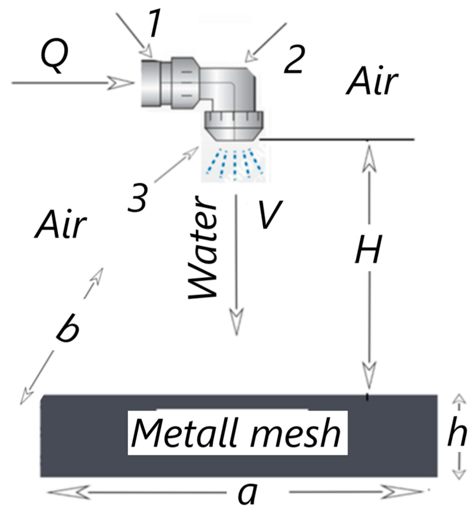
Figure 2 shows the schematic diagram of the adiabatic cooling process (model 2). The liquid (water) with the set volume flow rate Q (m3/s) flows from pipeline 1 to mixing chamber 2 of the tangential nozzle, where the water is swirled and discharged through outlet port 3 (nozzle) into the airspace. When the liquid film comes out of the nozzle, it disintegrates, forming a single flare (jet) in the form of a cone and not limited by solid walls.
The nozzle is mounted at height H from the metal mesh with overall dimensions a × b × h = 2000 mm × 1140 mm × 222 mm and square cells of 16 mm × 16 mm.
Boundary conditions: For the numerical solution of the problem at the inlet to the L-shaped pipeline, the volumetric flow rate of water was set based on each nozzle: for case 1—Q = 0.00025 m3/s, for case 2—Q = 0.000666 m3/s. The ambient temperature (air) TAIR and the temperature of the liquid (water) TWATER entering the pipeline and then into the nozzles are equal to each other. TAIR = TWATER = 293.20 K (20 °C). Ambient pressure is equal to atmospheric p = 101325 Pa, density ρ = 1.2041 kg/m³, dynamic viscosity μ = 1.85 × 10⁻⁵ Pa∙s, specific heat capacity at constant pressure Cp = 1005 J/(kg∙deg).
Water: temperature TWATER = 293.20 K (20 °C), density ρ = 998.16 kg/m³, dynamic viscosity μ = 0.0010014 Pa∙s, specific heat capacity Cp = 4184.4 J/(kg∙deg). The metal mesh is modelled as an isotropic porous body (the permeability of the medium is the same in all directions inside the medium). The effective porosity of the medium is determined by Equation (1), as the volume fraction of the pores connected together Vpores in the total volume of the porous medium Vtotal:
ε = V p o r e s V t o t a l
In the case under consideration, the porosity of the medium is ε = 0.5, and it is set by default.
The permeability of the medium к is determined by formula (2):
k = Δ P V · L · ρ
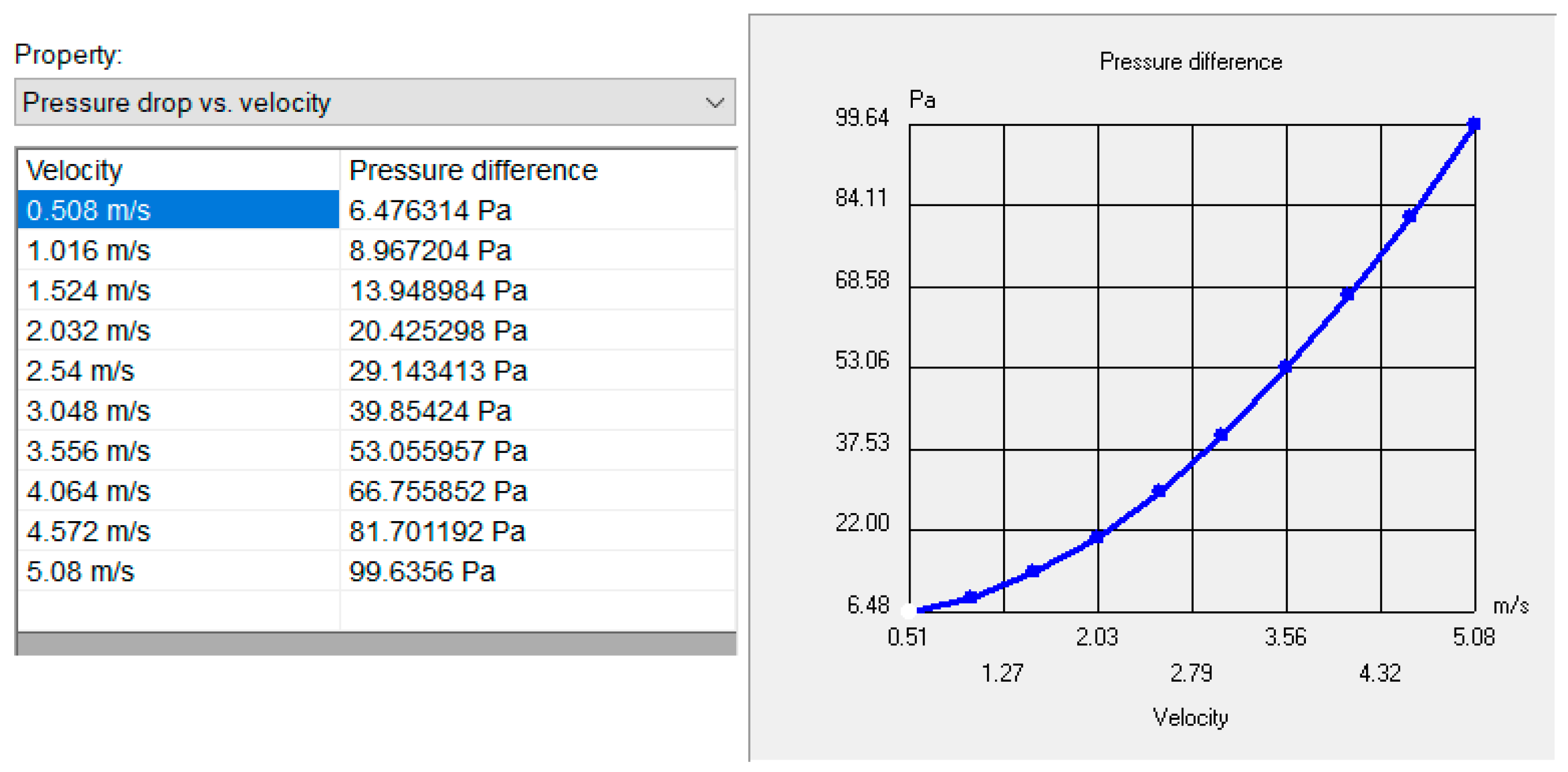
where ΔP—pressure difference between the opposite sides of the parallelepipedal porous body in the selected direction, Pa; V—flow rate of the fluid medium, m/s; ρ—fluid density, kg/m3; L—length of the body in this direction, mm. The dependence of the pressure difference ΔP (Pa) on the flow rate of the liquid V (m/s) is shown in Figure 3.
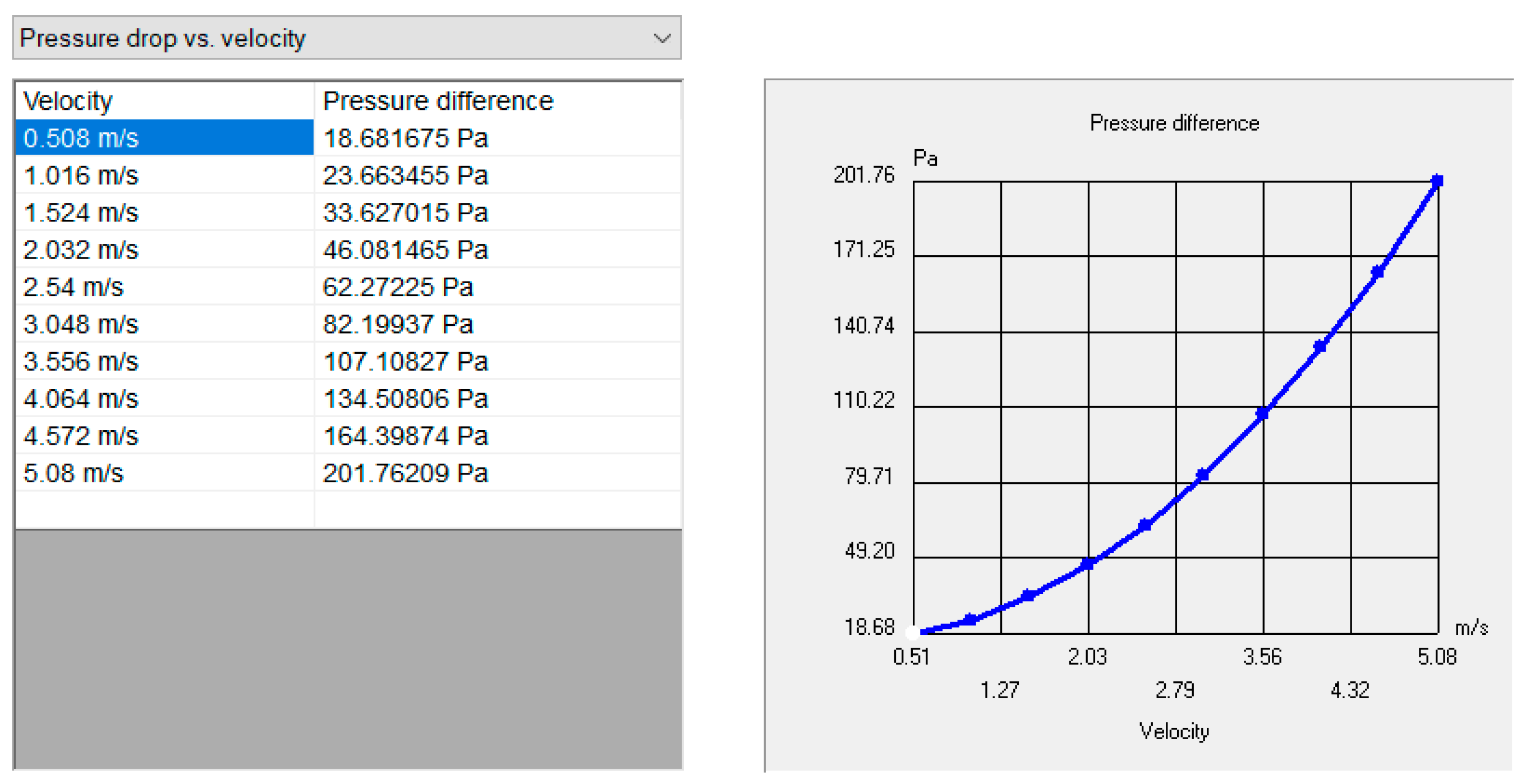
For the 2nd model, an additional metal mesh in front of the nozzles is modeled as well as an isotropic porous body. The dependence of the pressure drop ΔP (Pa) on the fluid flow rate V (m/s), for the case under consideration, is shown in Figure 4.
The calculation of particle motion was considered in a steady flow of a fluid medium. The model of a fluid medium with liquid particles in Flow Simulation assumes spherical particles of constant mass, the effect of which on the flow is negligible, but the flow affects the speed and temperature (and hence the density) of the particles, which in turn affects their size.
For the particle calculation, the initial conditions were set: the entry points of the particles into the fluid medium (the outlet of the nozzle); the initial parameters of the particles: liquid-water, temperature Tpartical = 293.20 K (20 °C), density ρ = 998.16 kg/m3, diameter-d = 100 µm and d = 500 µm, as well as the total mass flow (amount of particle mass, introduced by the fraction into the fluid per unit time) for the case of volume flow Q = 0.00025 m3/s-mass flow m = 0.249 kg/s, for Q = 0.000666 m3/s-m = 0.6376 kg/s. In particle motion calculation, gravity was taken into account, which was specified using the components of the gravitational acceleration vector in the global coordinate system.

2.1.2. Mathematical Formulation of the Problem

The non-steady-state Navier–Stokes equations, the energy equation (first law of thermodynamics), and the equation of [38,39,40,41] are used for mathematical modelling of the motion of the medium. For turbulent flows, the initial equations of Reynolds-averaged and additional stresses due to turbulent pulsations of parameters are taken into account [37]. The obtained non-closed system of equations is closed by means of additional equations for kinetic energy of turbulence k and dispersion of energy of turbulence ε in accordance with the known k-ε turbulence model [42].
The system of equations of conservation of momentum, mass, and energy describing turbulent, laminar, and transient flows of a compressible fluid with heat exchange can be represented as:
ρ u i t + χ j   ( ρ u i u j τ i j ) + P χ i = F i ,
ρ t + χ j   ( ρ u j ) = 0 ,
( ρ E ) T + χ i   ( ( ρ E + P ) u i + q i τ i j   u j ) = F i u i + Q H ,
ρ k t + χ i   ( ρ u i k ) = χ i   ( ( μ l + μ t σ k ) k χ i ) + S k ,
ρ ε t + χ i   ( ρ u i ε ) = χ i   ( ( μ l + μ t σ τ ) ε χ i ) + S τ ,
S k = τ i j R u i χ j ρ ε + μ t P B ;   ρ = P R T   ;   q i = ( μ l P r + μ t σ c ) c P T χ i ,
S ε = C ε 1 ε k   ( f 1 τ i j R u i χ j + μ t C B P B ) C ε 2 f 2 ρ ε 2 k ;   P B = g i σ B   1 ρ   ρ χ i ,
τ i j = ( μ l + μ t ) ( u i χ i + u j χ i 2 3   u l χ l δ i j ) 2 3 ρ k δ i j ; f 1 = 1 + ( 0.05 f μ ) 3 ;   f 2 = 1 e x p ( ( ρ k 2 μ l ε ) 2 ) ,
τ i j R = μ t ( u i χ i + u j χ i 2 3   u l χ l δ i j ) 2 3 ρ k δ i j ,
μ t = f μ C μ ρ k 2 ε ;   f μ = [ 1 e x p ( 0.025 ρ k y μ l ) ] 2 · ( 1 + 20.5   μ l ε ρ k 2 ) ,
where u, p, ρ, T—velocity, pressure, density, and temperature of the fluid, R—gas constant, t—time, Fi—total force acting on a unit of mass, E—total energy of the unit of mass of the fluid, QH—source of heat per unit volume, qi—diffusion flow of heat, δij—Kronecker symbol, τij—tensor of viscous shearing stresses, τ i j R ρ u i u j —stress tensor in the Reynolds model, μL—dynamic coefficient of viscosity, μt—coefficient of turbulent viscosity, y—distance from the solid wall, gi—components of gravitational acceleration in the direction of xi; σ c ,   σ B ,   σ k ,   σ ε ,   C B ,   C μ ,   C ε 1 ,   C ε 2 —empirical constants; Cp—specific heat capacity at constant pressure; λ—coefficient of thermal conductivity of gas (fluid); Pr = μcp/λ—Prandtl number; for laminar flow the parameters k, μt, ε—are equal to zero; x, y, z—current coordinates; summing takes place using the suffix numbers i, j = x, y, z.
This paper used the Flow Simulation CAE engineering software, in which the Navier–Stokes equations were solved numerically using the finite volume method.
Before starting the calculation, an approximation of the surfaces of solids (nozzles and metal mesh) in contact with the fluid medium is made, and for this the procedure of local fragmentation of the mesh cell near these areas of surfaces is used. So, each cell of the base mesh, intersected by the surface of a solid at the interface with a fluid medium, is divided into eight identical, geometrically similar cells of a smaller size. The discrete solution of the formulated continuous (differential) mathematical problem obtained on the computational grid formed in this way generally depends on the size of the computational grid cells that cover the computational domain. To solve the given mathematical problem and estimate the achieved accuracy, several calculations were carried out on different, rarer, and more frequent computational grids. To achieve a satisfactory accuracy of solving a mathematical problem (grid convergence), it took about 400,000 elements.

2.1.3. Methods for Processing the Results of Numerical Calculations

Authors studied liquid drops with diameters d = 100 µm and d = 500 µm, which are formed during the decay of the jet flowing from nozzles f1 (right nozzle) and f2 (left nozzle) (Figure 1).
For each diameter of the droplet liquid, the following indicators were determined: velocity, viscosity, density, Reynolds criterion, which are included in the equations of heat and mass transfer coefficients (13), (14), as well as the efficiency of atomization (15) [43,44]. Data were taken along the trajectory of liquid droplets from the nozzle outlet to the adiabatic cooler. Currently, quite a lot of criterion equations are known for determining the coefficients of heat and mass transfer depending on the physicochemical properties and regime parameters obtained on the basis of experimental data [44]. In this work, criterial equations were chosen: for the mass transfer coefficient Sh—the Kinzer equation (13), for the heat transfer Nu—the Lyakhovsky equation (14). These equations are characterized by the fact that, regardless of the experimental conditions, the nature and physical properties of the liquid, these equations provide relatively accurate results in a wide range of the Reynolds criterion Re.
The mass transfer coefficient Sh, was determined according to Equation (13):
S h = 2 + 0.6 R e 0.5 · S c 0.33 ,
where Re—Reynolds number; Sc—Schmidt number.
The heat transfer coefficient Nu, Equation (14):
N u = 0.62 · R e 0.5 ,
Atomization efficiency η, Equation (15):
η = 12 σ d · ρ · w 2 ,
where σ is the coefficient of surface tension of a liquid drop; d—droplet diameter (m), ρ—liquid density (kg/m3); w—the speed of droplet movement (m/s).
The calculation of particle motion allows obtaining visualized images how liquid particles with mass (droplet) are distributed in the flow.

3. Results and Discussion

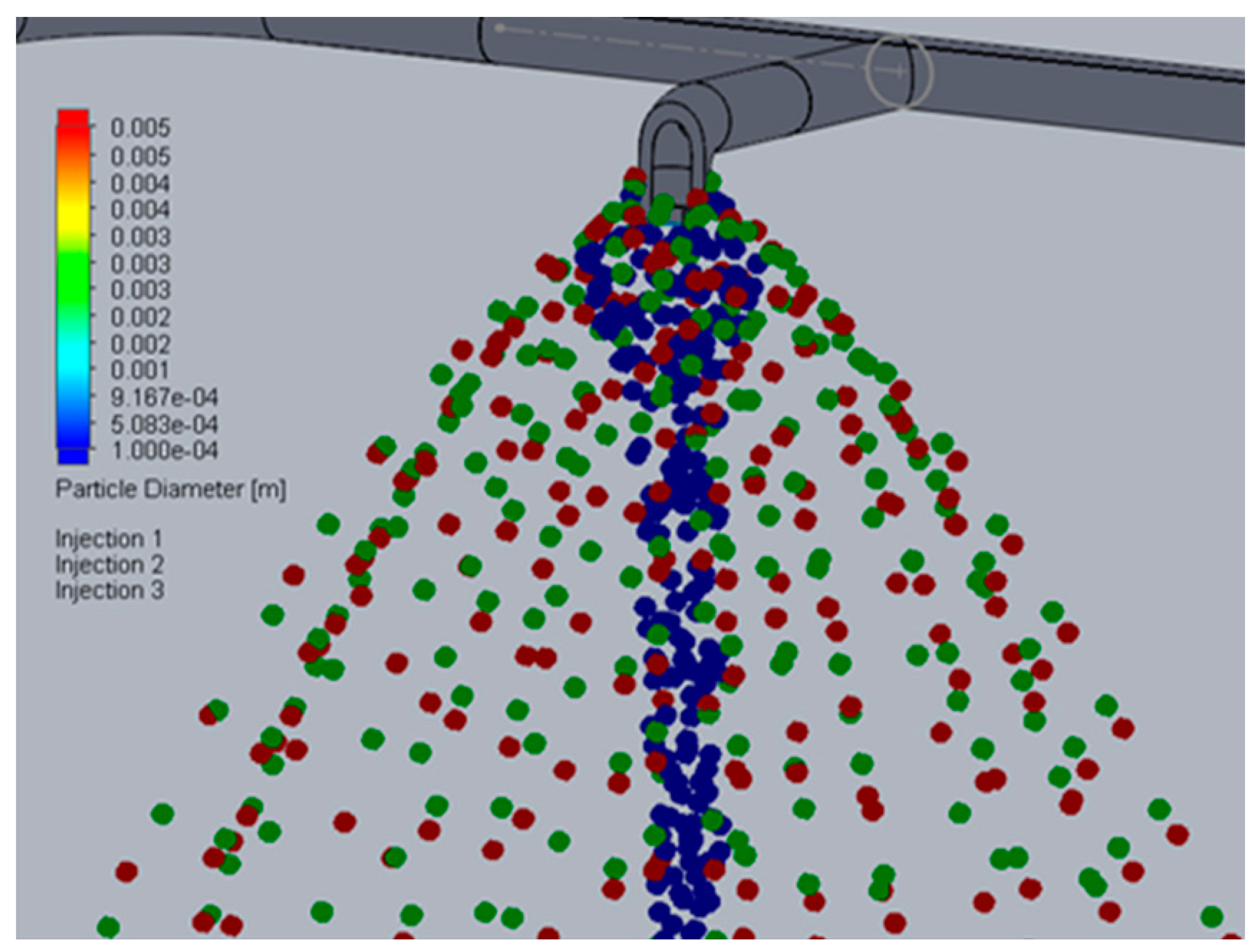
The results of the numerical calculation showed (visualization of the pattern of the distribution of liquid drops in Figure 5) that a finer spray of liquid droplets d = 100 µm (Figure 5 blue drops) is closer to the jet axis. Drops of larger diameter d = 500 µm (red color drops) are concentrated at the periphery of the jet. The data obtained are consistent with the known literature data [43,44].
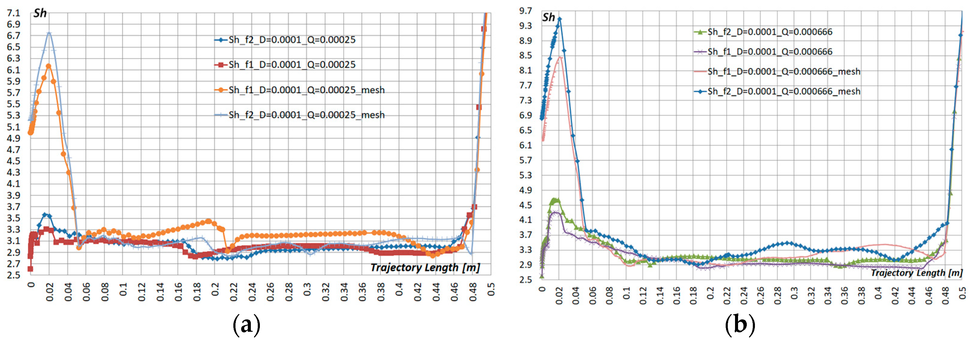
Figure 6a,b shows the results of a numerical calculation of the mass transfer coefficient Sh relative to the trajectory of the particle from the nozzle outlet (f1—right nozzle, f2—left nozzle) to the pre-cooler pad. For cases Q = 0.00025 m3/s (Figure 6a), and Q = 0.000666 m3/s (Figure 6b) with and without installed metal pad mesh in front of the nozzle. Liquid particle diameter d = 500 µm Figure 6a,b. Liquid particle diameter d = 100 µm Figure 7a,b.
The average values of the mass transfer coefficient Sh are summarized in Table 1.
The obtained results show that for the particle diameter d =100 µm and Q = 0.00025 m3/s, a low mass transfer coefficient Sh is typical for both the first and second nozzles. However, the installed metal pad mesh increases the Sh coefficient for both nozzles by ≈15%.
For particle diameter d = 500 µm and Q = 0.00025 m3/s, compared to particles d = 100 µm, there is a noticeable increase in the coefficient Sh ≈ by 70–80%. At the same time, with a metal pad mesh for d = 500 µm, Sh increases by 20–40%.
A similar pattern was also observed at Q = 0.000666 m3/s, for particles d = 500 µm and d = 100 µm, compared with Q = 0.00025 m3/s. The Sh coefficient increases, and the installed metal pad mesh increases Sh ≈ up to 30%.
Such changes in the Sh coefficient are due to two main parameters: the kinematic viscosity of the liquid, and the Reynolds number of a liquid drop, which are included in Equation (13). At the same time, for liquid drops d = 500 µm compared to d = 100 µm, the Reynolds number increases by ≈40–60%, and the kinematic viscosity of the liquid by ≈2–16%.
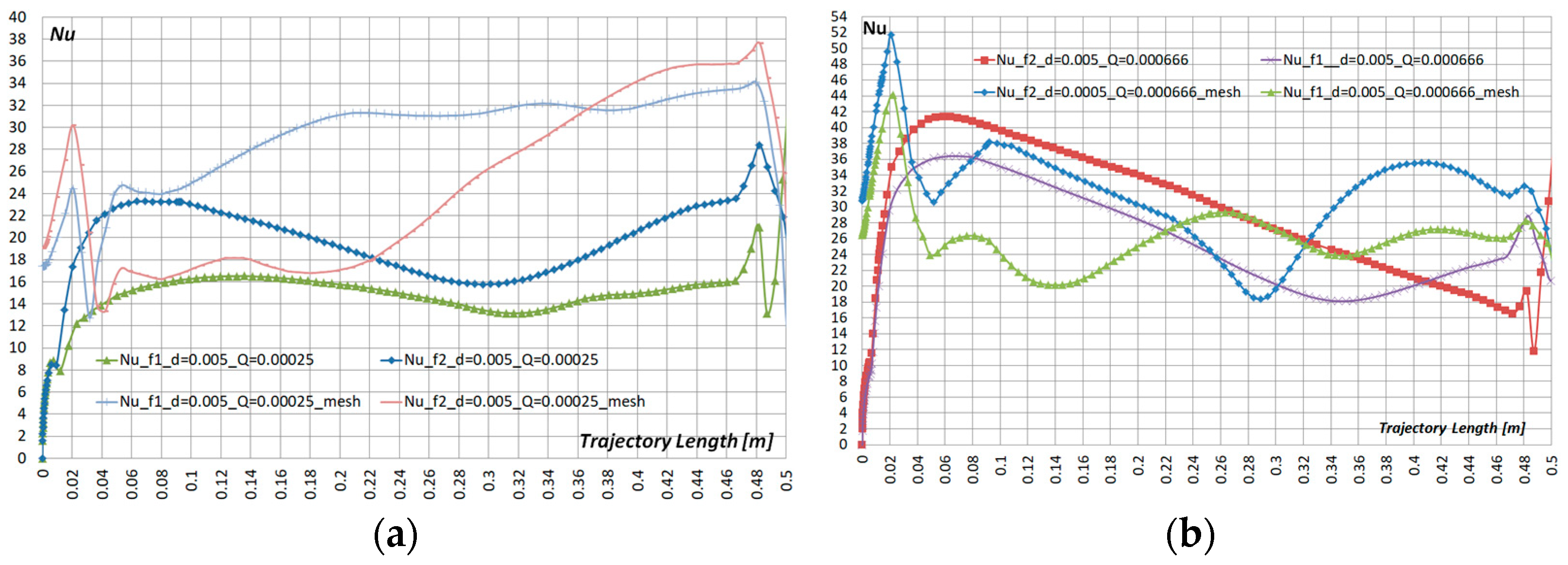
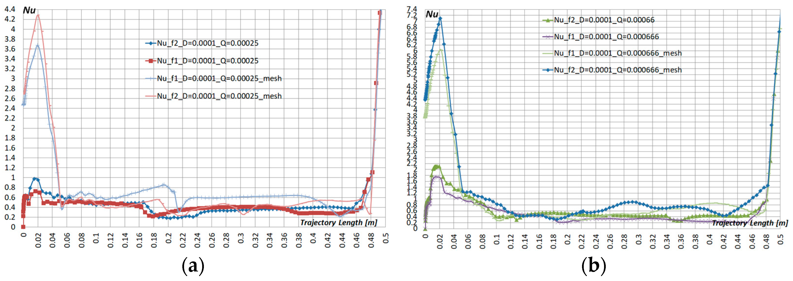
Figure 8a,b shows the results of a numerical calculation of the heat transfer coefficient Nu relative to the trajectory of the particle from the nozzle outlet (f1—right nozzle, f2—left nozzle) to the pre-cooler pad. For cases Q = 0.00025 m3/s (Figure 9a), and Q = 0.000666 m3/s (Figure 9b) with and without installed metal pad mesh in front of the nozzle. Liquid particle diameter d = 500 µm Figure 8a,b. Liquid particle diameter d = 100 µm Figure 9a,b.
The average values of the heat transfer coefficient Nu are summarized in Table 2.
The obtained results show that for particle diameters d = 100 µm and Q = 0.00025 m3/s, Q = 0.000666 m3/s, a low heat transfer coefficient Nu is relevant for both the first and second nozzles. At d = 500 µm and the same liquid flow rates, the heat transfer coefficient Nu increases significantly compared to particles d = 100 µm and can reach 90%. It is connected with the increase in the Reynolds number included in Equation (14).
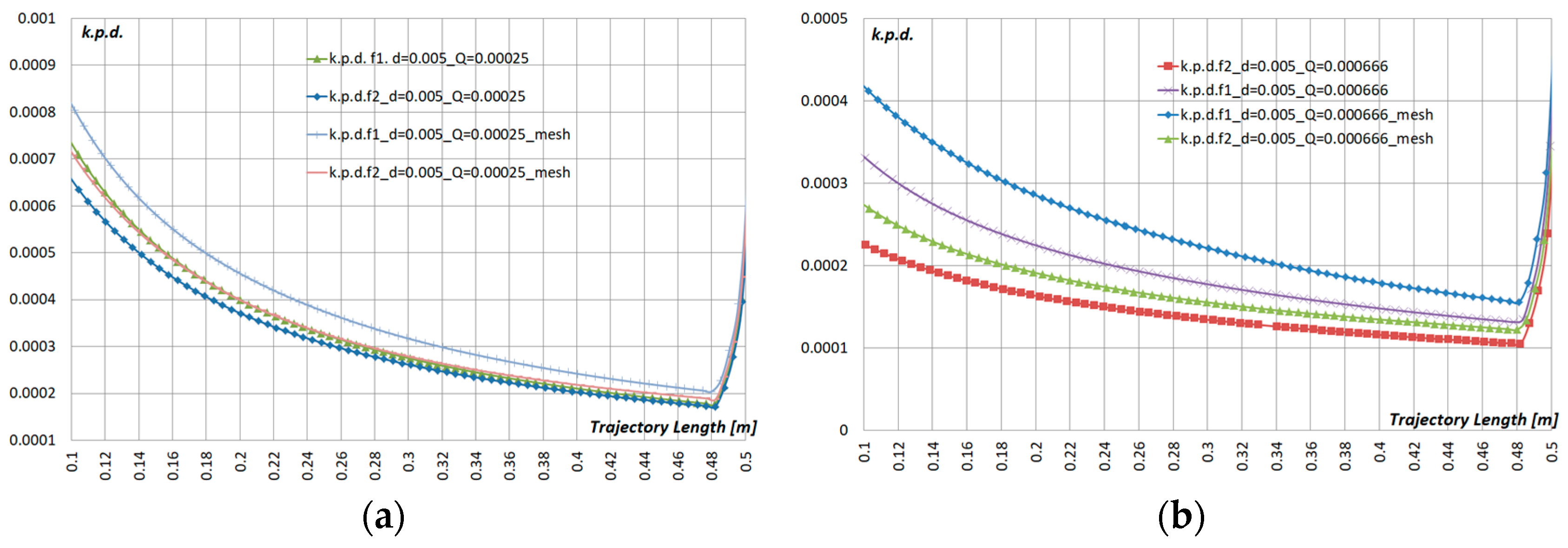
Figure 10 and Figure 11 show the results of the atomization efficiency η. It has to be noted that, according to the known data [43,44], the energy used on the formation of a new surface is not substantial—the efficiency of spraying usually does not exceed hundredths of a percent (the highest efficiency for hydraulic nozzles is about 0.04%)—and depends primarily on the physical properties of the liquid. Average atomization efficiencies are summarized in Table 3.
The atomization efficiency is not uniform, and the highest efficiency is observed at liquid flow rate Q = 0.00025 m3/s and d =100 µm, d = 500 µm, at the first nozzle η = 0.054. However, the installed metal pad mesh, in all other cases, improves the efficiency value by ≈30–40%.
During the disintegration of the jet, the interaction of forces of various nature on the surface of the liquid disrupts its integrity and crushing occurs. These forces include the forces of inertia, surface tension, aerodynamic forces, and viscous friction forces. To estimate the relationship between the forces in this work, the characteristic Reynolds numbers Re (14), Weber We (16) were used [43].
W e = d · ρ · w 2 σ ,
where w—the speed of droplet movement (m/s); d—the particle diameter (m); ρ—the density of the liquid (kg/m3); σ—the force of the surface tension of the liquid (N/m).
The analysis of the obtained results showed, for example, for the case of a given calculated volumetric flow rate Q = 0.0006 m3/s, the value of the average value of the criterion Re d = 500 along the trajectory of the liquid particle for d = 500 µm is much higher than its value, compared to Re d = 100 for particles d = 100 µm. That is, Re d = 500 > Re d = 100 or Re d = 500 = 1560 > Re d = 100 = 9.45. A similar picture is also observed for the Weber test: We d = 500 > We d = 100 or We d = 500 = 486 > We d = 100 = 11.58.
Calculations taking into account the additional installed mesh and without it, showed that the criterion Re(mesh) d = 100 for d = 100 µm almost doubles Re(mesh) d = 100 > Re d = 100, Re(mesh) d = 100 = 22.76 > Re d = 100 = 9.45. For d = 500 µm, 1.2 times Re(mesh) d = 500 > Re d = 500, Re(mesh) d = 500 = 1967 > Re d = 500 = 1560. In this case, the criterion We decreases, and for d = 100 µm is We(mesh) d = 100 = 7.9, i.e., tends to the minimum value WeKp = 7. Presumably, passing through the additional mesh (obstacle) the velocity of liquid particles decelerates and breaks up. The average droplet velocity at a distance from the nozzle outlet to the exit from the additional mesh is two times less than in the calculations without the mesh w(mesh) < w, w(mesh) = 0.85 m/s < w = 1.6 m/s.
For d = 500 µm, We(mesh) d = 500 = 386 < We d = 500 = 486, taking into account that the criterion We (mesh) is in the range 10 < We < 104, then the form of droplet destruction occurs in the same way, as in the case considered above, for d = 500 µm, We d = 500.
Based on the above, it can be assumed that a significant influence on the value of the heat and mass transfer criteria, as well as on the efficiency, is influenced by the diameter of the liquid droplets, their physical properties, as well as additional forces affecting the flow of the dropping liquid.
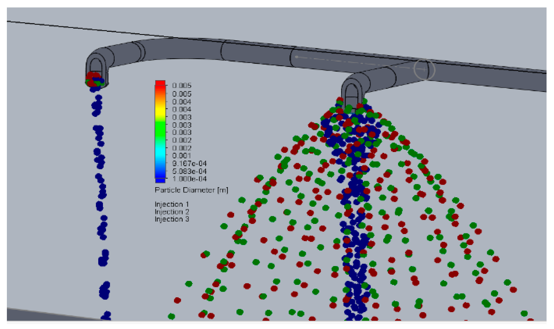
Figure 12 shows the pattern of liquid particle atomization formation at the initial moment of time, that is, when the flow of the supplied liquid in the pipeline with a given volumetric flow rate has not yet been established. It can be seen that in the right nozzle (f1), the torch (jet) is already fully formed, and in the left nozzle (f2) it is just beginning to form. At the same time, spraying of a finer fraction of a particle with a diameter of d =100 μm (blue particles) is already observed at both nozzles and is closer to the axis of the torch (jet). The spray of larger particles with a diameter of d = 300 µm (green particles) and d = 500 µm (red particles) at the right nozzle is already fully formed, at the left nozzle in the inlet section, these particles are just beginning to form. Such non-uniformity of the spray may be due to the fact that when the liquid moves through the distribution pipeline on which the nozzles are installed, there is a gradual decrease in the flow rate and velocity of the liquid in the pipe.
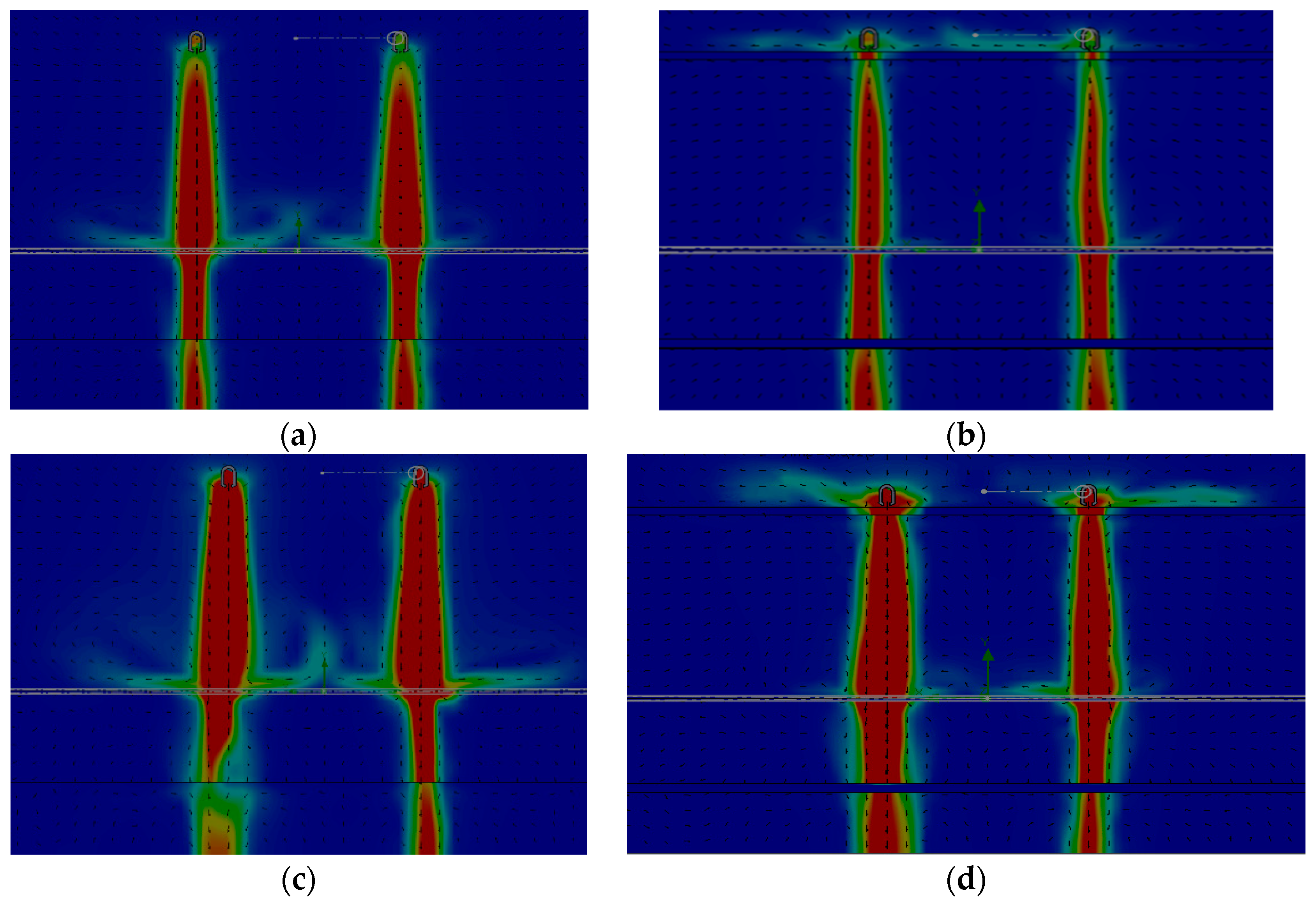
In Figure 13 the distribution patterns of the liquid flow rate for a given volumetric flow rate Q = 0.00025 m3/s are presented: (a) without metal pad mesh and (b) with metal pad mesh. The figures show that the installation of the metal pad mesh somewhat narrows the liquid jet, but at the same time, when it reaches the pre-cooler pad, it reduces the intensity of vortex formation and the liquid flow passes through the pad mesh more evenly.
Figure 13 shows the distribution patterns of the liquid flow rate for the volumetric flow rate Q = 0.000666 m3/s: (c) without metal pad mesh and (d) with metal pad mesh. In the case with a lower flow rate, for the scenario with metal pad mesh, there is noticeably less intense vortex formation above the pre-cooler pad. It is also observed that there is less obvious compression of the jet and a more uniform distribution of the fluid flow velocity, when passing through the metal mesh.
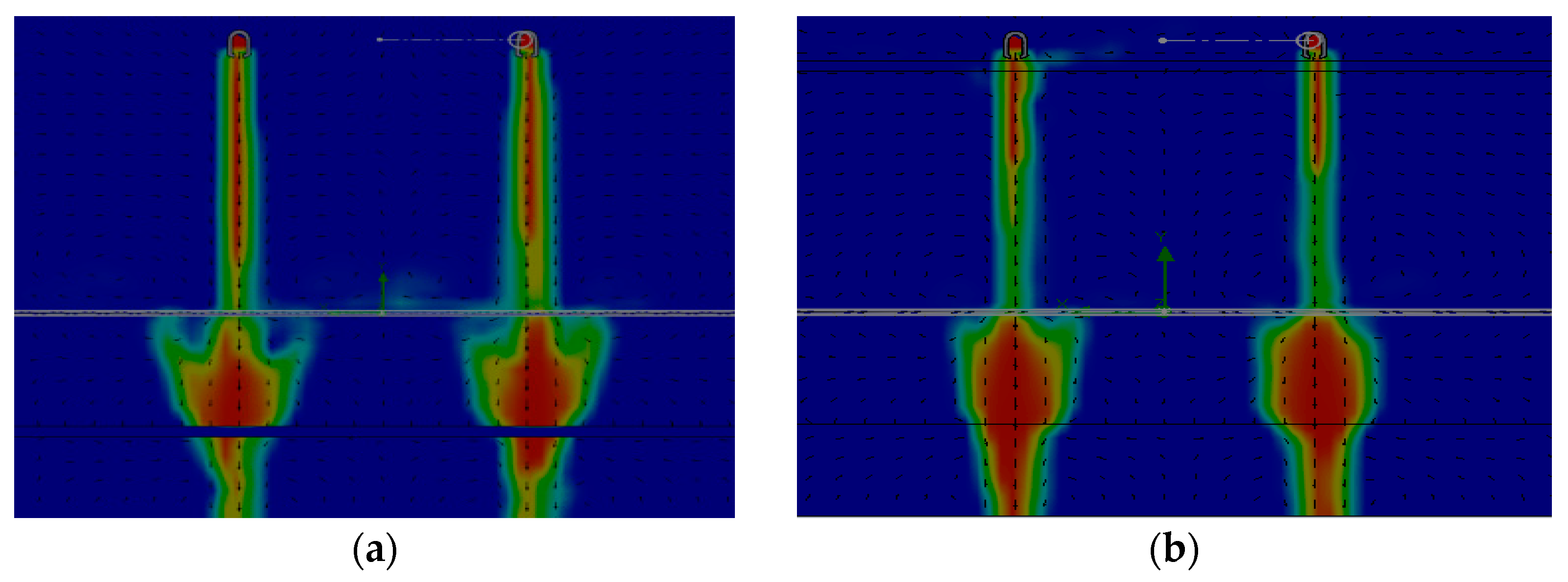
Figure 14 shows the distribution of mass concentration of water in the calculated volume filled with air (front view) for water flow Q = 0.00025 m3/s and for Q = 0.000666 m3/s: (c) without metal pad mesh and (d) with metal pad mesh. The figure shows that the mass concentration of water is more evenly distributed in the adiabatic cooler for the case with the installed metal pad mesh. Presumably, such a distribution is achieved by less intense vortex formation above the pre-cooler.
To assess the accuracy of solving the problem, a free jet was considered, created by a single tangential nozzle of the TG 20 × 12 type, moving in space in the absence of side walls. A three-dimensional model of the nozzle was built according to the geometric dimensions presented in the datasheet. Nozzle flow characteristics in the range Q = 0.9 m3/h −2.4 m3/h. Working pressure p = 29.42–343 kPa.
During the calculation, the jet opening angle, the distribution of liquid droplets in a jet with a given diameter, density, viscosity, velocities, and pressure required for calculation of the Reynolds and Weber numbers were determined.
Comparative analysis of calculation results with theoretical studies [44] showed:
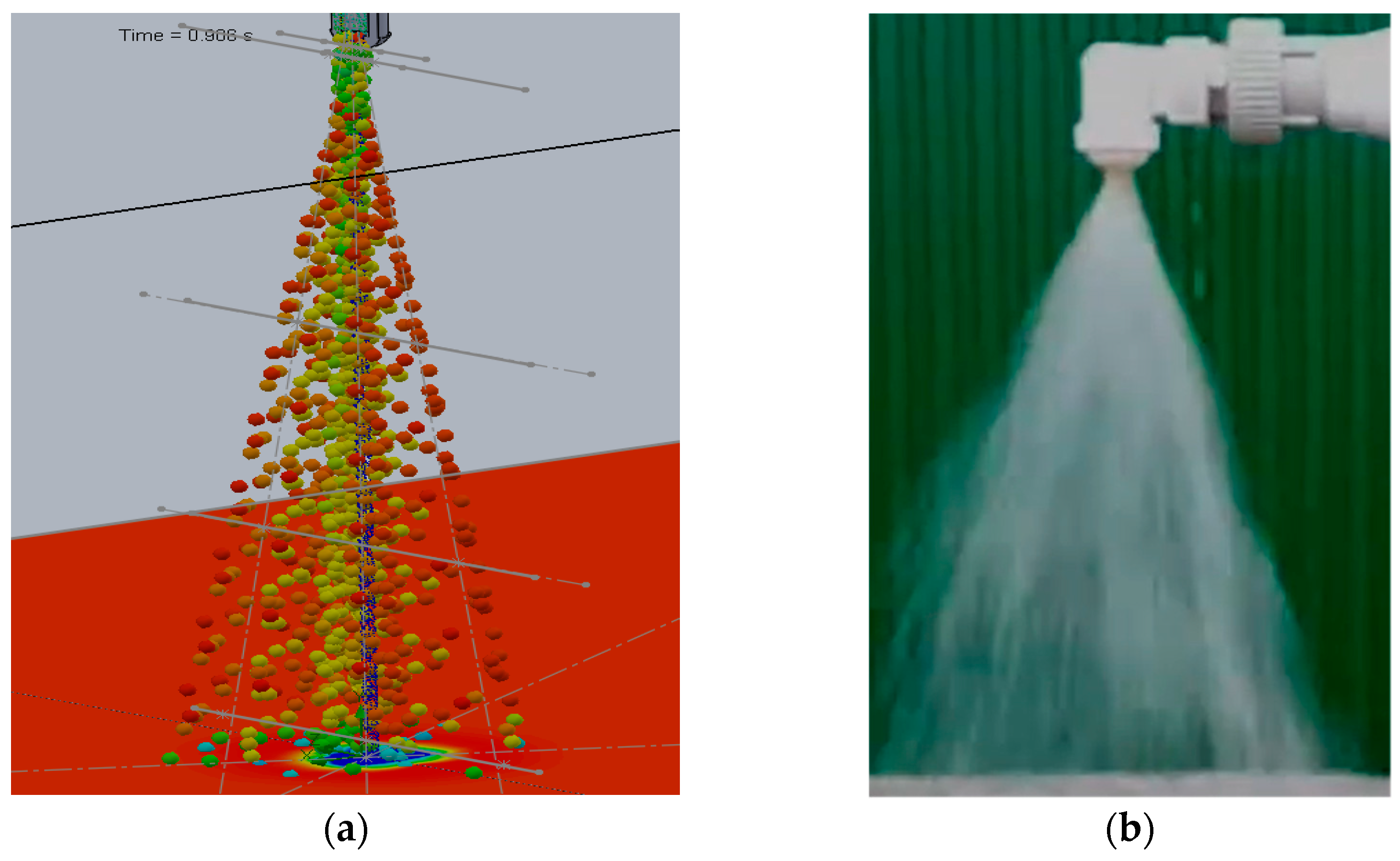
The theoretical jet opening angle was calculated according to the well-known method described in [44]. The obtained numerical solution well matched with the results of the theoretical calculation of the jet, and the error does not exceed 10%. Jet opening angle (theoretical) φteoret = 20°, numerical calculation φnc = 22°. Figure 15 shows visualization of the distribution of a steady liquid jet for a volumetric flow rate Q = 0.00025 m3/s: (a) numerical calculation (visualization is presented in the form of a dropping liquid), (b) experiment. Figure 15a shows that the shape of the outflowing jet, at the outlet of the nozzle, has a small section of a cylindrical shape, and further downstream the jet opens up, taking a full cone-shaped shape. A similar flow was observed in the experiment (see Figure 15b).
The speed of the drops w along the trajectory are not uniform and as the jet breaks up it is w = 0.5–3 m/sec. Drops of a smaller diameter d = 100 mkm create a cylindrical jet, at d = 500 mkm a conical jet, in the general case, creating a full-cone jet. The result of the calculation is well matched with the manufacturer experimental visualized data of the considered type of nozzle.
At a volumetric flow rate of liquid Q = 0.9 m3/h, there are two zones of disintegration of liquid droplets: in the first zone 1 Weber criterion 0.1 ≤ We∙Re−0.5 ≤ 0.8 (zone 1), division into 2–4 drops occur, the “bag” is destroyed and chaotic fragmentation; in the second zone 0.8 ≤ We∙Re−0.5 ≤ 10, droplets are destroyed with a breakdown of the surface layer, giving a very fine spray along with large secondary particles separated from the original drop. In this case the calculated working pressure is in the range p = 102.32–104.82 kPa; it does not exceed the working pressure, according to the manufacturer datasheet of the nozzle.
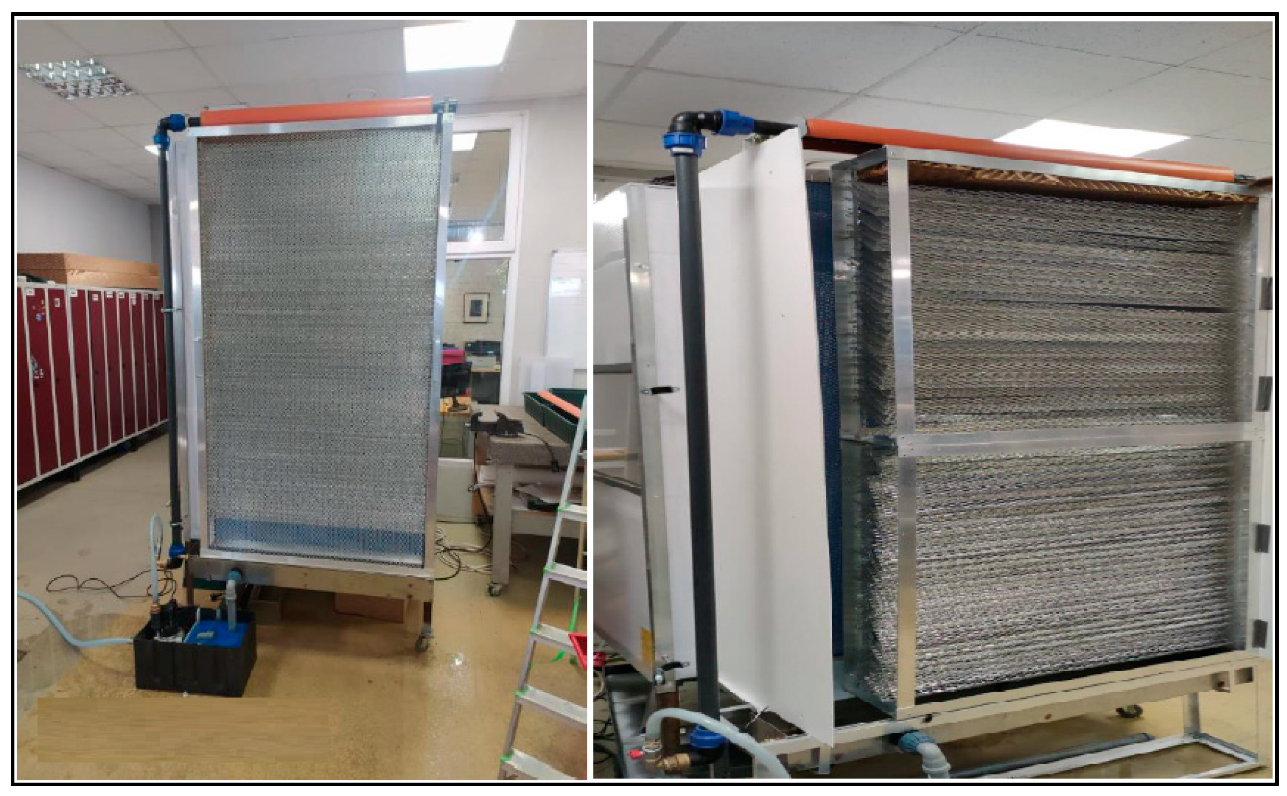
All of the above-studied cases, as well as this research, are dedicated to improving the efficiency of evaporative air conditioning equipment. In the study [32], experiments were carried out under laboratory conditions (Figure 16) to identify the pre-cooling potential of various types of metal mesh intended as cooling pads of various shapes (W, Z, Z1) with square cells of 16 × 16 mm (Figure 17). In the presented case, a straight metal mesh was modeled (a flat, non-curved metal pad mesh). In the future, it is planned to create models in SolidWorks for various metal mesh shapes (W, Z, Z1) and validate the model with real measurements. The created models will help to quickly and efficiently select the required sizes and shapes of pre-cooling pads, as well as to optimize the water/air supply, thereby increasing the efficiency of evaporative air conditioning equipment.
The previous study on this subject [29] show that the environmental benefit of the evaporative cooling system is superior to that of the conventional system with annual electricity saving potential in the ballpark of 45–50% which consequently reduces CO2 emissions produced by power plants. Increasing the area of the pre-cooler pad, by using the metal mesh intended as cooling pads of various shapes, will significantly reduce fossil fuel consumption during peak loads. The distribution of water on the adiabatic cooling pad’s mesh surface also plays an important role in the performance of an evaporative cooler. In addition, precise control of water atomization helps to reduce the environmental impact of cooling processes by reducing water consumption.

4. Conclusions

The main conclusions are summarized below:
  • It was revealed in the considered design cases, that when the liquid is supplied through the pipeline to the nozzles from one side in the presented design they do not work evenly.
  • Assessment of the accuracy of the problem under consideration showed agreement with the results of theoretical studies and manufacturer experimental visualized data.
  • The results of calculating the mass transfer coefficient showed that for particles d = 100 μm, Q = 0.00025 m3/s, and Q = 0.000666 m3/s, a relatively low mass transfer coefficient Sh ≈ 3.3–3.5 is typical. The installation of metal pad mesh allowed to increase Sh ≈ 15%. For particles d = 500 µm, compared to particles d = 100 µm, the Sh coefficient increased by 70–80%, and the additional metal mesh increased Sh factor by another 20–40%.
  • Heat transfer coefficient Nu for d = 500 µm compared to particles d = 100 µm increased by 90% and the additional metal mesh increased Nu by another 20–40%.
  • The atomization efficiency has its own value for each nozzle and the highest atomization efficiency was observed at liquid flow rate Q = 0.00025 m3/s and d = 100 µm, d = 500 µm. An additional metal pad mesh, in all other cases considered, improved the efficiency value by ≈30–40%.
  • Visualization patterns of the fluid flow rate showed that at the jet periphery, upon impact with an adiabatic pre-cooler pad, return flows were formed, which, presumably, affected the uniformity of the liquid mass concentration in the pre-cooler itself. The installation of an additional metal pad mesh makes it possible to reduce vortex formation above the pre-cooler pad and, as a result, to equalize the uniformity of the distribution of the mass concentration of the liquid.
  • Processing the simulation results, it was found that the use of metal pad mesh promotes the smoothest and most uniform water distribution of pre-cooling pad that improves environmental benefit by increasing efficiency values by ≈20–40% and reducing the water consumption of the system by ≈15–20%.

Author Contributions

Conceptualization, A.B. and K.L.; methodology, A.B. and A.P.; software, N.S.; validation, K.L. and A.P.; formal analysis, A.B., K.L., N.S. and A.P.; investigation, A.B, K.L. and N.S.; data curation, A.B.; writing—original draft preparation, A.B. and K.L.; writing—review and editing, A.B. and K.L.; visualization, N.S.; supervision, A.B.; project administration, A.B. All authors have read and agreed to the published version of the manuscript.

Funding

This research received no external funding.

Institutional Review Board Statement

Not applicable.

Informed Consent Statement

Not applicable.

Data Availability Statement

Not applicable.

Acknowledgments

This research is supported by ERDF project “Development of a new proto-type of adiabatic cooling panels to ensure the sustainability and energy efficiency of cooling equipment”, Nr. 1.1.1.1/19/A/002.

Conflicts of Interest

The authors declare no conflict of interest.

References

  1. Xue, J.; Ding, J.; Zhao, L.; Zhu, D.; Li, L. An option pricing model based on a renewable energy price index. Energy 2022, 239, 122117. [Google Scholar] [CrossRef]
  2. Sen, D.; Tunç, K.M.; Günay, M.E. Forecasting electricity consumption of OECD countries: A global machine learning modeling approach. Util. Policy 2021, 70, 101222. [Google Scholar] [CrossRef]
  3. Waite, M.; Cohen, E.; Torbey, H.; Piccirilli, M.; Tian, Y.; Modi, V. Global trends in urban electricity demands for cooling and heating. Energy 2017, 127, 786–802. [Google Scholar] [CrossRef] [Green Version]
  4. Hischier, R.; Böni, H.W. Combining environmental and economic factors to evaluate the reuse of electrical and electronic equipment–a Swiss case study. Resour. Conserv. Recycl. 2020, 166, 105307. [Google Scholar] [CrossRef]
  5. Mir, A.; Alghassab, M.; Ullah, K.; Khan, Z.; Lu, Y.; Imran, M. A Review of Electricity Demand Forecasting in Low and Middle Income Countries: The Demand Determinants and Horizons. Sustainability 2020, 12, 5931. [Google Scholar] [CrossRef]
  6. International Energy Agency’s (IEA). The Future of Cooling Opportunities for Energyefficient Air Conditionin; IEA: Paris, France, 2018. [Google Scholar]
  7. Alawadhi, M.; Phelan, P.E. Review of Residential Air Conditioning Systems Operating under High Ambient Temperatures. Energies 2022, 15, 2880. [Google Scholar] [CrossRef]
  8. Titova, E.M.; Averyanova, O.V. Efficiency evaluating of air conditioning system with air dehumidification section. Mag. Civ. Eng. 2011, 19, 46–52. [Google Scholar] [CrossRef]
  9. Tejero-González, A.; Franco-Salas, A. Optimal operation of evaporative cooling pads: A review. Renew. Sustain. Energy Rev. 2021, 151, 111632. [Google Scholar] [CrossRef]
  10. Farnham, C.; Yuan, J. Possible Perception Bias in the Thermal Evaluation of Evaporation Cooling with a Misting Fan. Clean Technol. 2021, 3, 183–205. [Google Scholar] [CrossRef]
  11. Nada, S.; Fouda, A.; Mahmoud, M.; Elattar, H. Experimental investigation of energy and exergy performance of a direct evaporative cooler using a new pad type. Energy Build. 2019, 203, 109449. [Google Scholar] [CrossRef]
  12. Fouda, A.; Melikyan, Z. A simplified model for analysis of heat and mass transfer in a direct evaporative cooler. Appl. Therm. Eng. 2011, 31, 932–936. [Google Scholar] [CrossRef]
  13. Somwanshi, A.; Sarkar, N. Design and analysis of a hybrid air and water cooler. Eng. Sci. Technol. Int. J. 2019, 23, 101–113. [Google Scholar] [CrossRef]
  14. Eidan, A.A.; Alwan, K.J.; AlSahlani, A.; Alfahham, M. Enhancement of the Performance Characteristics for Air-Conditioning System by Using Direct Evaporative Cooling in Hot Climates. Energy Procedia 2017, 142, 3998–4003. [Google Scholar] [CrossRef]
  15. Atmaca, I.; Şenol, A.; Çağlar, A. Performance testing and optimization of a split-type air conditioner with evaporatively-cooled condenser. Eng. Sci. Technol. Int. J. 2021, 32, 101064. [Google Scholar] [CrossRef]
  16. Afonicevs, V.; Strauts, U.; Bogdanovs, N.; Lesinskis, A. Evaporative cooling technology efficiency compared to traditional cooling system–case study. In Proceedings of the 19th International Scientific Conference Engineering for Rural Development, Jelgava, Latvia, 20−22 May 2020. [Google Scholar] [CrossRef]
  17. Rashmi, S.; Nihar, S.; Amol, P. Addressing Water Consumption of Evaporative Coolers with Greywater; Lawrence Berkeley National Laboratory: Berkeley, CA, USA, 2012.
  18. Bhatkar, V.W. Determination of water loss for an adiabatic cooling of a fin fan water cooler. Mater. Today Proc. 2021, 47, 5629–5631. [Google Scholar] [CrossRef]
  19. Rafique, M.M.; Gandhidasan, P.; Rehman, S.; Al-Hadhrami, L.M. A review on desiccant based evaporative cooling systems. Renew. Sustain. Energy Rev. 2015, 45, 145–159. [Google Scholar] [CrossRef]
  20. Yamada, H.; Yoon, G.; Okumiya, M.; Okuyama, H. Study of cooling system with water mist sprayers: Fundamental examination of particle size distribution and cooling effects. Build. Simul. 2008, 1, 214–222, In: IBPSA 2007-International Building Performance Simulation Association 2007. [Google Scholar] [CrossRef] [Green Version]
  21. Khangembam, C.; Singh, D.; Handique, J.; Singh, K. Experimental and numerical study of air-water mist jet impingement cooling on a cylinder. Int. J. Heat Mass Transf. 2020, 150, 119368. [Google Scholar] [CrossRef]
  22. Fawzy, H.; Zheng, Q.; Jiang, Y.; Lin, A.; Ahmad, N. Conjugate heat transfer of impingement cooling using conical nozzles with different schemes in a film-cooled blade leading-edge. Appl. Therm. Eng. 2020, 177, 115491. [Google Scholar] [CrossRef]
  23. Sadafi, M.; Jahn, I.; Hooman, K. Nozzle arrangement effect on cooling performance of saline water spray cooling. Appl. Therm. Eng. 2016, 105, 1061–1066. [Google Scholar] [CrossRef] [Green Version]
  24. Bao, J.; Wang, Y.; Xu, X.; Niu, X.; Liu, J.; Qiu, L. Analysis on the influences of atomization characteristics on heat transfer characteristics of spray cooling. Sustain. Cities Soc. 2019, 51, 101799. [Google Scholar] [CrossRef]
  25. Sun, T.; Huang, X.; Chen, Y.; Zhang, H. Experimental investigation of water spraying in an indirect evaporative cooler from nozzle type and spray strategy perspectives. Energy Build. 2020, 214, 109871. [Google Scholar] [CrossRef]
  26. Sajjad, U.; Abbas, N.; Hamid, K.; Abbas, S.; Hussain, I.; Ammar, S.M.; Sultan, M.; Ali, H.M.; Hussain, M.; Rehman, T.U.; et al. A review of recent advances in indirect evaporative cooling technology. Int. Commun. Heat Mass Transf. 2021, 122, 105140. [Google Scholar] [CrossRef]
  27. De Antonellis, S.; Joppolo, C.M.; Liberati, P.; Milani, S.; Molinaroli, L. Experimental analysis of a cross flow indirect evaporative cooling system. Energy Build. 2016, 121, 130–138. [Google Scholar] [CrossRef]
  28. Al-Zubaydi, A.Y.T.; Hong, G. Experimental study of a novel water-spraying configuration in indirect evaporative cooling. Appl. Therm. Eng. 2019, 151, 283–293. [Google Scholar] [CrossRef]
  29. Borodinecs, A.; Lebedeva, K.; Prozuments, A.; Brahmanis, A.; Grekis, A.; Zajecs, D.; Zekunde, A.; Vatin, N. Feasibility of reducing electricity consumption of air conditioning equipment by condenser direct evaporative cooling technology. Example of case study in dubai. Atmosphere 2021, 12, 1205. [Google Scholar] [CrossRef]
  30. Xu, P.; Ma, X.; Diallo, T.M.O.; Zhao, X.; Fancey, K.; Li, D.; Chen, H. Numerical investigation of the energy performance of a guideless irregular heat and mass exchanger with corrugated heat transfer surface for dew point cooling. Energy 2016, 109, 803–817. [Google Scholar] [CrossRef] [Green Version]
  31. Duan, Z.; Zhan, C.; Zhao, X.; Dong, X. Experimental study of a counter-flow regenerative evaporative cooler. Build. Environ. 2016, 104, 47–58. [Google Scholar] [CrossRef]
  32. Prozuments, A.; Brahmanis, A.; Mucenieks, A.; Jacnevs, V.; Zajecs, D. Preliminary Study of Various Cross-Sectional Metal Sheet Shapes in Adiabatic Evaporative Cooling Pads. Energies 2022, 15, 3875. [Google Scholar] [CrossRef]
  33. Lee, K. Principles of CAD/CAM/CAE Systems; Pearson Education: London, UK, 1999. [Google Scholar]
  34. Russell, S.; Norvig, P. Artificial Intelligence: A Modern Approach, 2nd ed.; Prentice Hall: Hoboken, NJ, USA, 2002. [Google Scholar]
  35. Norenkov, I.P.; Kuzmik, P.K. Information Support for High Technology Products (CALS technologies); Bauman Moscow State Technical University: Moscow, Russia, 2002; 320p, ISBN 5-7038-1962-8. (In Russian) [Google Scholar]
  36. Kolchin, A.F.; Ovsyannikov, M.V.; Strekalov, A.F.; Sumarokov, S.V. Product Life Cycle Management. 2007, LLC “Anacharsis”, Moscow (2002). Available online: https://context.reverso.net/translation/english-russian/product+life-cycle+management (accessed on 1 June 2022). (In Russian).
  37. Alyamovsky, A.A.; Sobachkin, A.A.; Odintsov, E.V.; Kharitonovich, A.I.; Ponomarev, N.B. SolidWorks. Computer modeling in engineering practice. In Proceedings of the InMotion Project Final Conference, Saint Petersburg, Russia, 27–29 June 2005. (In Russian). [Google Scholar]
  38. Petrila, T.; Trif, D. Basics of Fluid Mechanics and Introduction to Computational Fluid Dynamics; Springer: Berlin/Heidelberg, Germany, 2005. [Google Scholar] [CrossRef]
  39. Wilcox, D.C. Turbulence Modeling for CFD; DCW Industries: La Canada, CA, USA, 1993. [Google Scholar]
  40. Loytsyansky, L.G. Mechanics of Liquid and Gas. Master’s Thesis, Samara University, Samara, Russia, 2003. (In Russian). [Google Scholar]
  41. Janna, W.S. Introduction to Fluid Mechanics, Fifth Edition; Taylor Francis Group: Abingdon, UK, 2015. [Google Scholar] [CrossRef]
  42. The 3DEXPERIENCE Company. Dassault Systèmes Provides Business and People with Virtual Universes to Imagine Sustainable Innovations Capable of Harmonizing Product, Nature and Life. Available online: https://www.3ds.com/ (accessed on 25 May 2022).
  43. Pazhi, D.G.; Galustov, V.S. Sprays of Liquid; Khimiya: Moscow, Russia, 1979. (In Russian) [Google Scholar]
  44. Pazhi, D.G.; Galustov, V.S. Fundamentals of Spraying Technology; Khimiya: Moscow, Russia, 1984. (In Russian) [Google Scholar]
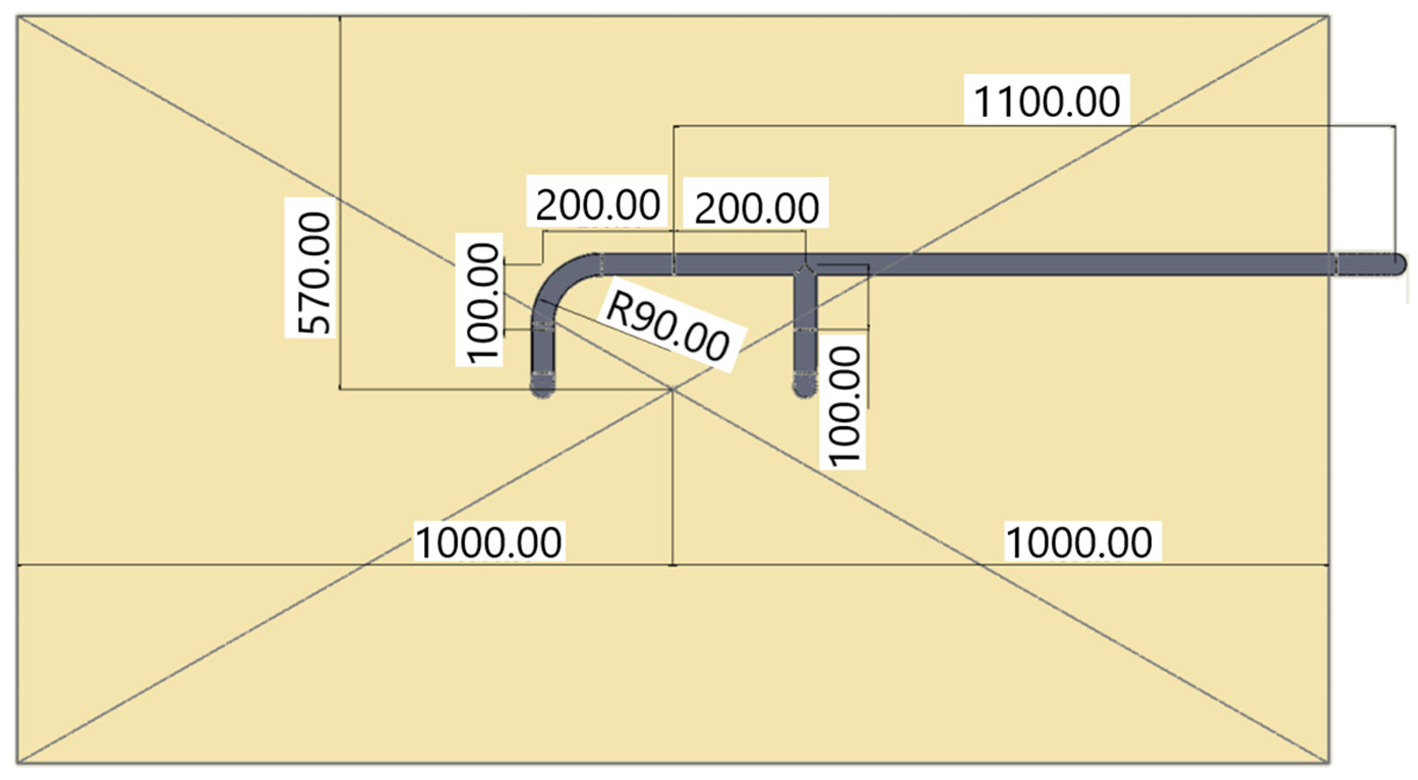
Figure 1. Assembly drawing of an adiabatic cooler top view.
Cleantechnol 04 00044 g001
Figure 2. Diagram of the adiabatic cooling process.
Cleantechnol 04 00044 g002
Figure 3. Dependence of pressure difference ΔP (Pa) on the flow rate of the liquid V (m/s).
Cleantechnol 04 00044 g003
Figure 4. Dependence of pressure difference ΔP (Pa) on the flow rate of the liquid V (m/s).
Cleantechnol 04 00044 g004
Figure 5. Visualizing the distribution pattern of liquid droplets.
Cleantechnol 04 00044 g005
Figure 6. Mass transfer coefficient Sh, d = 500 µm: (a) Q = 0.00025 m3/s; (b) Q = 0.000666 m3/s.
Cleantechnol 04 00044 g006
Figure 7. Mass transfer coefficient Sh, d = 100 µm: (a) Q = 0.00025 m3/s; (b) Q = 0.000666 m3/s.
Cleantechnol 04 00044 g007
Figure 8. Heat transfer coefficient Nu, d = 500 µm: (a) Q = 0.00025 m3/s; (b) Q = 0.000666 m3/s.
Cleantechnol 04 00044 g008
Figure 9. Heat transfer coefficient Nu, d = 100 µm: (a) Q = 0.00025 m3/s; (b) Q = 0.000666 m3/s.
Cleantechnol 04 00044 g009
Figure 10. Atomization efficiency η, d = 500 µm: (a) Q = 0.00025 m3/s; (b) Q = 0.000666 m3/s.
Cleantechnol 04 00044 g010
Figure 11. Atomization efficiency η, d = 100 µm: (a) Q = 0.00025 m3/s; (b) Q = 0.000666 m3/s.
Cleantechnol 04 00044 g011
Figure 12. The pattern of liquid particle atomization formation.
Cleantechnol 04 00044 g012
Figure 13. Fluid flow rate distribution patterns for: Q = 0.00025 m3/s: (a) without metal pad mesh and (b) with metal pad mesh; Q = 0.000666 m3/s: (c) without metal pad mesh and (d) with metal pad mesh.
Cleantechnol 04 00044 g013
Figure 14. The distribution of mass concentration of water for: Q = 0.00025 m3/s: (a) without metal pad mesh and (b) with metal pad mesh; Q = 0.000666 m3/s: (c) without metal pad mesh and (d) with metal pad mesh.
Cleantechnol 04 00044 g014aCleantechnol 04 00044 g014b
Figure 15. Visualization of the distribution of a steady liquid jet for a volume flow Q = 0.00025 m3/s. (а) Numerical calculation, (b) experiment.
Cleantechnol 04 00044 g015
Figure 16. Testing setup in laboratory conditions.
Cleantechnol 04 00044 g016
Figure 17. Example of different testing metal mesh.
Cleantechnol 04 00044 g017
Table 1. The average values of the mass transfer coefficient Sh.
Q = 0.00025ShQ = 0.000666Sh
d = 0.0001f13.311782f13.509563
f23.320845f23.676473
f1 mesh3.942006f1 mesh4.540239
f2 mesh3.943016f2 mesh4.930458
d = 0.005f116.11704f124.17137
f219.87923f227.27551
f1 mesh28.44891f1 mesh28.66047
f2 mesh25.21438f2 mesh34.43927
Table 2. The average values of the heat transfer coefficient Nu.
Q = 0.00025NuQ = 0.000666Nu
d = 0.0001f10.719422f10.927462
f20.728958f21.099443
f1 mesh1.369552f1 mesh1.992825
f2 mesh1.372388f2 mesh2.396427
d = 0.005f114.17148f122.49213
f218.05553f225.70276
f1 mesh26.90797f1 mesh27.19304
f2 mesh23.56767f2 mesh33.09933
Table 3. The average atomization efficiencies η.
Q = 0.00025ηQ = 0.000666η
d = 0.0001f10.054693f10.016712
f20.037475f20.010037
f1 mesh0.020881f1 mesh0.04781
f2 mesh0.023857f2 mesh0.031201
d = 0.005f10.054693f10.000359
f20.000796f20.00024
f1 mesh0.002619f1 mesh0.000906
f2 mesh0.001852f2 mesh0.000664
Publisher’s Note: MDPI stays neutral with regard to jurisdictional claims in published maps and institutional affiliations.