Article

Understanding the Anomalous Corrosion Behaviour of 17% Chromium Martensitic Stainless Steel in Laboratory CCS-Environment—A Descriptive Approach

1
Department of Engineering and Life Sciences, University of Applied Science—HTW Berlin, 12459 Berlin, Germany
2
BAM Federal Institute of Materials Research and Testing, 12205 Berlin, Germany
*
Author to whom correspondence should be addressed.
Clean Technol. 2022, 4(2), 239-257; https://doi.org/10.3390/cleantechnol4020014
Submission received: 16 December 2021 / Revised: 7 February 2022 / Accepted: 14 March 2022 / Published: 24 March 2022
(This article belongs to the Special Issue CO2 Capture and Sequestration 2020)

Abstract

:
To mitigate carbon dioxide emissions CO2 is compressed and sequestrated into deep geological layers (Carbon Capture and Storage CCS). The corrosion of injection pipe steels is induced when the metal is in contact with CO2 and at the same time the geological saline formation water. Stainless steels X35CrMo17 and X5CrNiCuNb16-4 with approximately 17% Cr show potential as injection pipes to engineer the Northern German Basin geological onshore CCS-site. Static laboratory experiments (T = 60 °C, p = 100 bar, 700–8000 h exposure time, aquifer water, CO2-flow rate of 9 L/h) were conducted to evaluate corrosion kinetics. The anomalous surface corrosion phenomena were found to be independent of heat treatment prior to exposure. The corrosion process is described as a function of the atmosphere and diffusion process of ionic species to explain the precipitation mechanism and better estimate the reliability of these particular steels in a downhole CCS environment.

Graphical Abstract

1. Introduction

The sequestration of carbon (carbon capture and storage (CCS [1,2]) comprises the sequestration, transport and injection of emission gasses into a deep geological layer. This technique is well acknowledged to mitigate climate change. Safe deep onshore or offshore geological layers—mainly saline aquifers (brine)—offer storage sites for emission gases that arose mostly from combustion processes of cement production or power plants [1,2,3,4]. Due to the highly corrosive environment, especially at the phase boundaries of metal, CO2 and saline aquifer water injection pipe steels are highly exposed to CO2 corrosion [3,4,5,6,7,8,9] directly dependent on multiple criteria [5,6,10,11,12,13,14,15,16,17,18,19,20,21,22,23,24,25,26,27,28,29,30,31]:
  • Temperature (60 °C is a severe damaging temperature region);
  • CO2 partial pressure;
  • alloy composition;
  • heat treatment of steels (austenitizing temperature and durance as well as annealing
  • element distribution in the corrosive media);
  • purity of alloy and aquifer media;
  • conditions of flow;
  • pressure during injection and;
  • protecting corrosion scales.
Alloy composition [22] and heat treatment [23,24,25,26,27,28,29,30] are the main determining factors influencing corrosive phenomena. Surface corrosion is mainly reduced by high nickel and chromium percentages [26,27]. Local corrosion of martensitic steels is reduced through the presence of retained austenite [26], the higher temperature during austenitizing [28,29,30] and annealing [22,23,28]. Surface corrosion recedes as a function of increasing austenitizing time [16] but is neglectable regarding local corrosion [32,33,34], compared to the ferritic or ferritic-bainitic microstructure martensitic steels containing carbon and manganese, which show low corrosion resistance because grain boundaries are highly reactive in NaCl containing H2S [31]. Different authors describe an immediate dependence of the corrosion behaviour on the surface condition after machining processes [35,36,37,38,39,40]. In general, the corrosion resistance increases with receding vertical height on the surface for carbon steel [35,36], austenitic stainless steel and ferritic stainless steel when the roughness exceeds 0.5 µm [38] and after shot peeing [39]. The initial surface roughness, however, has less effect than the relative humidity. In terms of protection and inhibition of internal pipeline corrosion, it is more beneficial to decrease the humidity than the initial surface roughness [37].
The potential of stainless steel X35CrMo17 (1.4122) is discussed and compared to the results of earlier studies with different high alloyed steels [16,17,41,42,43]. It is a heat treatable chromium steel that is highly resistant to a high number of organic and inorganic acids because of the high percentage of molybdenum. X35CrMo17 shows fairly good resistance to salt water. Moreover, its resistance to crevice corrosion up to 500 °C (working temperature) is improved.
The hardened martensitic stainless steel precipitation contains about 3% copper X5CrNiCuNb16-4 (1.4542, AISI 630) and is characterized by small copper precipitates that are distributed within the matrix which ensure the mechanism of precipitation hardening [44]. Small niobium and copper carbides are embedded in the martensitic bcc-structured microstructure [41]. This increases the alloys’ strength and permits excellent mechanical properties and, at the same time, good resistance against corrosive attack [16]. However, martensitic 1.4542 is prone to stress corrosion cracking (SCC) and the martensitic microstructure is less corrosion resistant than the solution-treated microstructure that (as a drawback) shows reduced strength [45,46,47,48,49,50,51,52]; (Note that the resistance against corrosive attack is higher although the strength is low in the solution-treated state) [51,52]).
Surface corrosion rates at 60 °C are generally independent of heat treatment prior to exposure at ambient pressure and neglectable at 100 bar. Corrosion rates below 0.005 mm/year are reported after long exposure to CCS environment (8000 h) [16]. The corrosion behaviour is rather attributed to chromium content and atmosphere than heat treatment.
Low corrosion rates in the liquid (CO2-saturated aquifer water) and even lower in the supercritical phase (water-saturated CO2) are linked to passivation and possibly insufficient electrolytes [48,49]. In the supercritical phase, cathodic reactions result in a higher H2CO3 concentration (after a solution of CO2 in water) and therefore in a higher acidic and more reactive surrounding as in the CO2 saturated liquid phase [7,26]. As a function of time corrosion, rates increase at 60 °C and 100 bar in the supercritical phase and remain stable in the liquid phase (0.003 mm/year after 4000 h) [16]. Sufficient surface corrosion resistance at ambient pressure is related to the microstructure of hardened or hardened and tempered alloys [16]. Surface corrosion resistance at 100 bar under supercritical CO2 conditions is mentioned for hardened and tempered alloys at 670 °C (<0.001 mm/year, martensitic microstructure). By normalizing the microstructure, good corrosion resistance in the liquid phase is offered (ca. 0.004 mm/year, ferritic-pearlitic microstructure) [16,51,53].
The authors relate depassivation after long exposure (100 h) in the supercritical phase to fast reaction kinetics and carbide precipitation in earlier studies [16]. Because depassivation is accompanied by depleting the matrix of chromium, new passivation is prohibited and the material degrades [16,51,53]. Consequently, both phenomena lead to the unusual formation of a surface corrosion layer (Figure 1).
When these 17% chromium steels are exposed to the carbon dioxide environment, the corrosion layer produced on both, the pits and surface are compared to each other [15,17], usually composed of siderite FeCO3 [3,16,51]. FeCO3 shows low solubility in water (pKsp = 10.54 at 25 °C [16,26,29,43,54]), which causes anodic iron dissolution that is initialized by the formation of transient iron hydroxide Fe(OH)2 [6,16,49]. The pH elevates locally and causes reactions [15,29] to form a ferrous carbonate film internally as well as externally. This paper derives a descriptive approach to better understand this corrosion mechanism and offers a descriptive approach when this laboratory research is extended to small-scale applied research, for example, to monitor injection sights in CCS-sights. Revision times of the plant may be scheduled according to the corrosion type and scale formation with a possibly positive influence on the corrosion resistance of pipe steels in a geothermal environment.

2. Materials and Methods

To better understand corrosion behaviour in CCS, environment steel coupons were statically immersed in environments as existing during carbon capture and storage.

2.1. Steels

Static corrosion tests at ambient and high pressure (100 bar) were conducted with samples of:
  • No AISI (X35CrMo17, 1.4122) (Table 1);
  • AISI 630 (X5CrNiCuNb 16-4, 1.4542) (Table 2).
The chemical composition was reassured by spark emission spectrometry SPEKTROLAB M and by the electron probe microanalyzer JXA8900-RLn, JEOL, Tokyo, Japan (Table 1 and Table 2).

2.2. Aquifer Water

The geothermal condition (in-situ) requested for synthesized laboratory geothermal aquifer water (Stuttgart Aquifer [55,56] and Northern German Basin (NGB) [56,57]). This had to be conducted strictly ordered to avoid salts and carbonates precipitating early (Table 3).

2.3. Heat Treatment and Static Corrosion Experiments

As-received and thermally treated steel coupons with 8 mm thickness, 20 mm width, 50 mm length were immersed in 1. CO2-saturated aquifer brine and 2. Water-saturated CO2. For each exposure time, 4 coupons were tested. Depicted coupons were heat-treated following the protocol of Table 4 [9,15,16,17,32,34,41,49,51,52,58,59,60].
Specimens were tested in both the vapour and liquid phase, fixed through a hole of 3.9 mm. A capillary meter GDX600_man by QCAL Messtechnik GmbH, Munic surveyed the CO2 flow (purity 99,995 vol%) into the aquifer water in ambient pressure experiments at 3 NL/h. Specimens immersed for 700 to 8000 h at 60 °C and 100 bar in a high-pressure vessel [9,15,16,17,32,34,41,49,51,52,58,59] and additionally in a low pressure vessel at ambient pressure [9,15,16].
The surface of the steel coupons was ground under water down to 120 μm using SiC-paper. After executing corrosion experiments, samples were dissected, leaving the corrosion scales attached to the surface. After surface analysis, they were descaled with 37% HCl to conduct kinetic analysis). Embedding samples in Epoxicure, Buehler cold resin, allowing for smooth cutting and polishing (180 to 1200 μm) with SiC paper under water. Coupons were finished with 6 μm and 1 μm diamond paste. [16]

2.4. Analysis

Light optical and electron microscopy ensured analysis of morphology and layer structure of the corrosion scales. The double optical system MicroProf®TTV by FRT GmbH, Bergisch Gladbach, Germany uses three-dimensional images to characterize local corrosion. X-ray diffraction with CoK α-radiation and automatic slit adjustment, step 0.03° and count of 5 s in a URD-6 (Seifert-FPM) enabled phase analysis. The PDF-2 (2005) powder patterns were used to automatically identify peak positions. The most likely structures were matched with the inorganic crystal structural database ICSD and the POWDERCELL 2.4 program by the authors of [61] and the AUTOQUAN® by Seifert FPM Holding GmbH, Freiberg, Germany helped refine the fitting of raw data files. The image analysis program Analysis Docu ax-4 Aquinto Olympus Corporation, Olympus Deutschland GmbH, Hamburg, Germany a semi-automatic analyzing program, was used to predict corrosion kinetics. Therefore, the corrosion scale was measured according to the plane fraction of 3 microsections or according to a set of 30 line measurements of each 3 microsection frames, then deriving an estimated scale thickness. Material loss due to lateral spallation and/or corrosive attack was acquired via the mass change method using 4 coupons for each exposure time. The mass change of the coupons before and after exposure to the corrosive environment allowed for estimating surface corrosion rates according to DIN 50 905 part 1–4 (Equation (1)).
corrosion   rate   [ mm year ] = 8760 [ hours year ] × 10 [ mm cm ] × weight   loss [ g ] area [ cm 2 ] × density [ g cm 3 ] × time [ hour ]

3. Results and Discussion

CO2 is generally injected into saline aquifer water reservoirs in the supercritical state [9,15,16,17], where it reacts with brine salts and mineralizes quickly [55,56,57]. During technical revisions, the injection process is intermitted and the pressure in the injection pipe is reduced, which then leads to the raising of the water level into the pipe, and the brine may flow back into the borehole. The resulting three-phase boundary comprises of gaseous/supercritical CO2, liquid aquifer water, and solid-state steel from the injection pipe and enhances severe corrosive attack [16]. In laboratory experiments, one-year exposure to an artificial aquifer environment is sufficient to obtain meaningful corrosion data to reproduce the CCS environment and describe the corrosion mechanism [9,15].

3.1. Comprehensive Demonstration of Corrosion Kinetics

Checked against other possible injection pipe steels (42CrMo4, X20/46Cr13, X5CrNiCuNb16-4) X35CrMo17 shows very good corrosion resistance at ambient pressure in the liquid phase and 100 bar in both the supercritical and liquid phases (Figure 2 and Figure 3).
Surface corrosion rates accrete with elongated exposure time and are higher at ambient pressure compared to rates obtained at 100 bar—most likely a consequence of excess oxygen in the open test circuit [16,42]. Moreover, higher corrosion rates at ambient pressure could be attributed to an open capillary system drawing through the corrosion layer that is closed at 100 bar [16,41]. Open capillaries that are required for scale growth enable ionic species to interdependently diffuse fast [16,41]. In general, corrosion rates for X35CrMo17 (supercritical phase: max. 0.0065 mm/year after 8000 h of exposure at 100 bar and 0.096 mm/year after 8000 h of exposure at ambient pressure) are much lower compared to other steel qualities at 100 bar and with the exception of the intermediate phase also at ambient pressure. These generally lower corrosion rates are independent of the atmosphere (water-saturated supercritical CO2 intermediate (phase boundary) and CO2 saturated saline aquifer water) and indicate that the CO2 partial pressure is not sufficient to initiate the corrosive reactions described in the following chapters.
Note that independent of pressure (ambient pressure and at 100 bar), the corrosion rate of X35CrMo17 in water-saturated supercritical CO2 increases with exposure time, while the corrosion rate of samples exposed to CO2-saturated aquifer water decreases slightly, assuming that passivating corrosion layer precipitates (incubation time) (Figure 3). There are three possible reasons:
  • In general, the relative supersaturation of water-saturated CO2 (supercritical/vapour phase) is higher compared to CO2-saturated brine (liquid phase) because the concentration of reactive corrosion ions in the supercritical phase is higher than in the brine [16,41].
  • A possible final failure of the passivating layer exposes the newly formed metal surface to an electrolyte with high CO2 partial pressure that then accelerates the corrosion reactions.
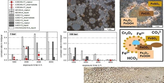
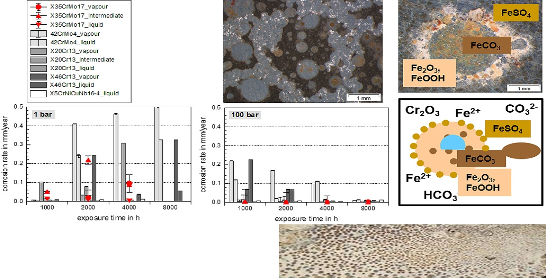
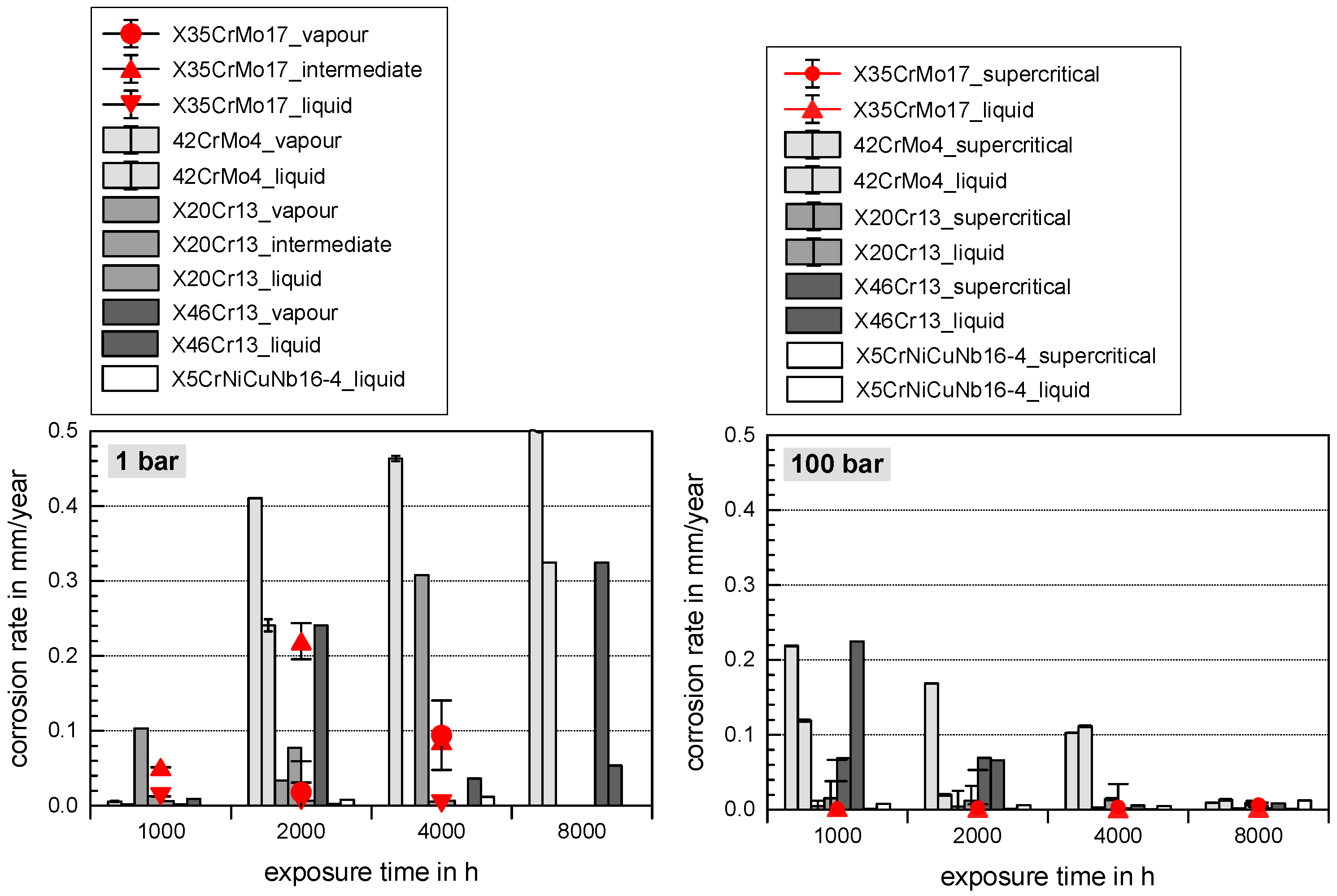
  • Long exposure times enhance carbide precipitation that depletes the surrounding metal matrix of chromium and prohibit surface passivation. Although independent of the pressure, the CO32− concentration remains the same [3], the higher corrosion rates in supercritical CO2 result in increased formation rate of Fe2+ ions, offering a high number of carbides precipitating on the steel’s surface. These are more susceptible to decomposing reactions, but carbides also affect the scale growth mechanism [3].
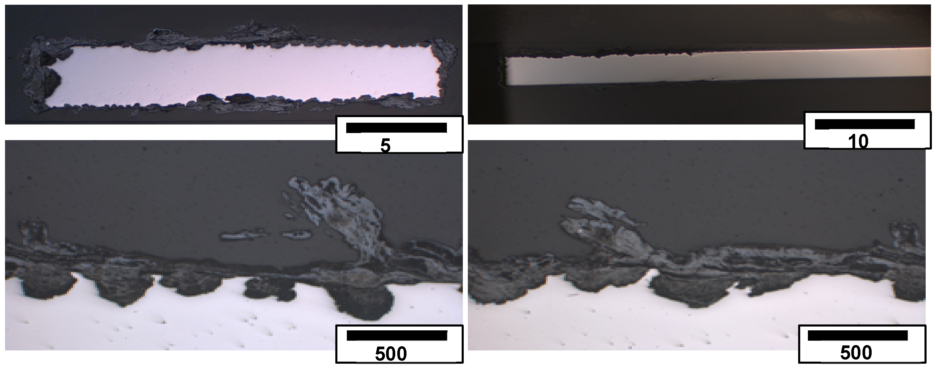
  • At high pressure with lower CO2 supersaturation in the liquid phase than in the supercritical phase, nucleation reactions are slow and stable crystal growth of siderite dominates the kinetics. A stable and dense siderite layer is formed, giving low corrosion rates in water-saturated supercritical CO2 as shown in Figure 2 and Figure 3.
As a consequence, the base metal decays after elongated exposure and corrosive reactions are accelerated in water-saturated supercritical CO2.
The impact of heat treatment on the corrosion behaviour of steels was shown earlier [11,16,17,22,28,29,41,51]. The heat treatment shows a stronger influence on the corrosion behaviour at 100 bar than at ambient pressure [16]. Good corrosion resistance at 100 bar in water-saturated supercritical CO2 (lowest surface corrosion rates: <0.001 mm/year) regarding surface corrosion in water-saturated supercritical CO2 and CO2-saturated saline water was attributed to martensitic microstructure, when steels are hardened and then annealed at 600–670 °C. However, it was shown that the normalized ferritic-pearlitic microstructure performs better in the CO2-saturated aquifer (ca. 0.004 mm/year) [16,41,51].
X35CrMo17 is less resistant against local corrosion at high pressure (100 bar) in the supercritical as well as the liquid phase [9,16,42] when compared to other possible injection pipe steel qualities (42CrMo4, X20Cr13, X46Cr13, X5CrNiCuNb16-4). X35CrMo17 is characterized by distinct pitting (pit per m2) with a generally higher number of pits under supercritical CO2 conditions [9,16,42] (Note that after 8000 h of exposure at ambient pressure, the number of pits per m2 increases tremendously, exceeding that obtained in the liquid phase). Figure 4 shows initial pits in combination with the surface corrosion layer precipitated in the vapour phase at ambient pressure and therefore clearly states that the corrosion mechanism is initiated by the formation of the pits.
In general, higher nickel and chromium contents in heat-treated steels rectify the corrosion resistance [16,22,27]. For X35CrMo17 and X5CrNiCuNb16-4, the increased chromium content leads to passivation layers, producing lower surface corrosion rates but insufficient reliability, according to enhanced local corrosion phenomena. Hence, the influence of the heat treatment is less meaningful than the influence of chromium content and atmosphere. Both steel qualities may be considered as injection pipe steels regarding surface corrosion criteria but not regarding local corrosion.

3.2. Surface Morphology and Scale Precipitation

The three-phase boundary: water, steel, and supercritical CO2 lead to the precipitation of thick corrosion layers in water-saturated CO2 at ambient pressure (Figure 5) and a “leopard”-shaped corrosion layer (Figure 1, Figure 5 and Figure 6) typical for martensitic stainless steels with 17% Chromium X5CrNiCuNb16-4 [16,51,53] and X35CrMo17 [16,41,42]. This corrosion formation is present in supercritical water-saturated CO2 and in CO2-saturated brine clearly after 2000 h of exposure at 60 °C and 100 bar. On average, the thickness of the corrosion layer formed on X35CrMo17 is about 0.8 mm locally the magnitude of the outer and inner corrosion layer exceeds the average by a factor of four [42]. Sample surfaces reveal ellipsoidal regions. The centres of the ellipsoidal regions are light-coloured, indicating corrosion layers revealing siderite FeCO3 and goethite alpha-FeOOH and also main precipitation phases [16,41,51]. The darker outer regions are not corroded at eyesight nor are they protected by a passivating layer.
Earlier phase analysis [9,42] for X35CrMo17 report various salts because alloying elements and iron from the base material react with the brine to form oxides, hydroxides and carbonates. The main phases of goethite α-FeOOH, mackinawite FeS and spinel phases of various compositions, for example, magnetite Fe3O4 and chromite FeCr2O4, arrange the complex multi-layer carbonate/oxide scale. Iron oxides are needle-shaped and halites NaCl precipitate in cubic habitus. Due to overlying peaks, siderite FeCO3 could not be identified via XRD but EDX-Scans of cross-sections definitely analysed siderite to be the scale matrix phase [9,41]. Rhodocrosite MnCO3, chromium iron oxide Cr1.3Fe0.7O3 and akaganeite Fe8O8(OH)8Cl1.34 are minor phases.
“Ellipsoids” (Figure 1, Figure 5 and Figure 6) show increased oxygen content compared to the surrounding surface (Figure 7, measuring position two). This refers to the fast growth of siderite, FeCO3. The oxygen content diminishes as a function of increasing distance from the centre of the ellipsoids. Therefore, only a thin passivating layer (possibly consisting of chromium iron oxide (Cr2O3 and (Fex(Cr1−x))3O4)) remains between the homogeneous ellipsoids.
In general, in contact with corrosive solutions (e.g., CO2-saturated saline aquifer water) a passive film is formed on the surface of high-alloyed high chromium stainless steels. This acts as a reaction ion barrier between the metal surface and the aggressive environment. The passivating layer, mainly composed of chromium oxide Cr2O3, prevents the mutual diffusion of Fe from the base metal and O2, C, S and other impurities from the CO2-saturated brine. It therefore protects the metal from further dissolution and degradation. In a CCS environment a Cr2O3 passivating layer also precipitates on high chromium steels. However, this may either be destroyed locally after precipitation or precipitate discontinuously, probably because of inhomogeneous carbide distribution or local changes in pH due to the formation of carbonic acid in CO2-saturated water or in water-saturated CO2. In water-saturated CO2 with pH 5.2–5.6, no stable chromium oxide film is formed (Figure 6) and local corrosion processes begin shortly after exposure. As a consequence, the leopard-shaped corrosion layer grows and reaches an equilibrium ellipsoid pattern with sufficient corrosion products (Figure 7, middle, indicated as measuring area (1) while the surrounding metal surface is still covered with the passivating layer (Figure 7, right, indicated as measuring area (2). (The oxygen and carbon content are too low for EDX analysis because the layer is less than 1-micrometer-thick.)

3.3. Corrosion Initiation in Water Saturated Supercritical CO2 (SCC)

Because the “leopard” shape phenomenon is clearly visible at 100 bar (at ambient pressure, the corrosion rate is high due to surplus oxygen in the experimental system and the leopard structure is soon overgrown) and in water-saturated CO2, the focus of this work is to describe the corrosion precipitation within this atmosphere.
Note, it may be assumed that the atmosphere (water-saturated supercritical CO2 or CO2-saturated brine) does not influence the corrosion mechanism because the leopard structure is present in both. Additionally, the corrosion phenomenon is assumedly independent of the microstructure of the steel because the “leopard” shape is found on coupons with ferrite-perlite microstructure as well as on coupons with martensitic or tempered martensitic microstructure (Figure 8). Mo and Ni do not seem to influence the corrosion mechanism either, because both steels show the same corrosion pattern, but one contains Ni and the other Mo. Because the steels’ surface mainly being covered by a passivating chromium oxide Cr2O3 layer, it is most likely that the high chromium content of 16% and 17%, respectively, are the driving force for this particular corrosion phenomenon. Earlier studies presenting results of steels with lower chromium content (42CrMo4 (1% Cr) or X46Cr13 and X20Cr13 (each 13% Cr) [16] show pitting and discontinuous but layered corrosion precipitates.
The authors previously outlined the initiation of the typical “leopard” surface structure [41,51] and now present the most possible scenarios for corrosion in water-saturated supercritical CO2:
(a)
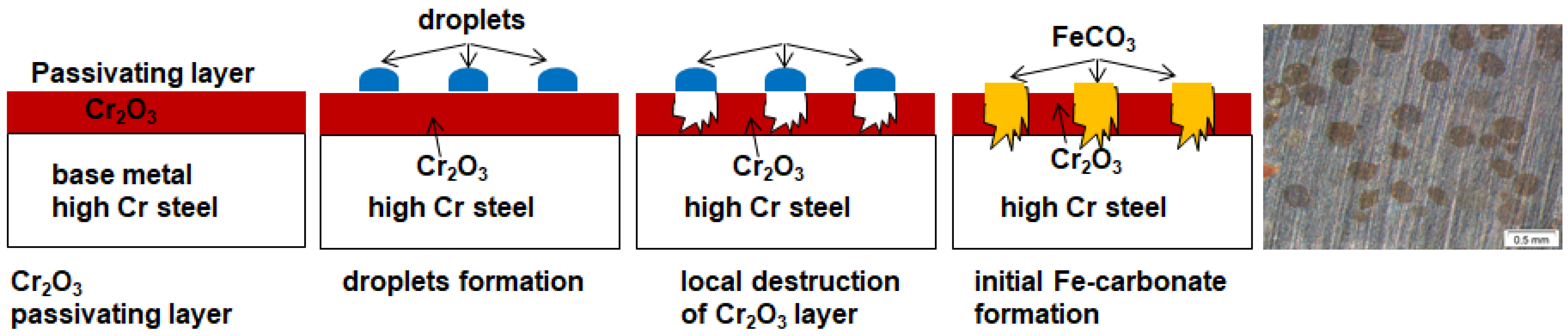
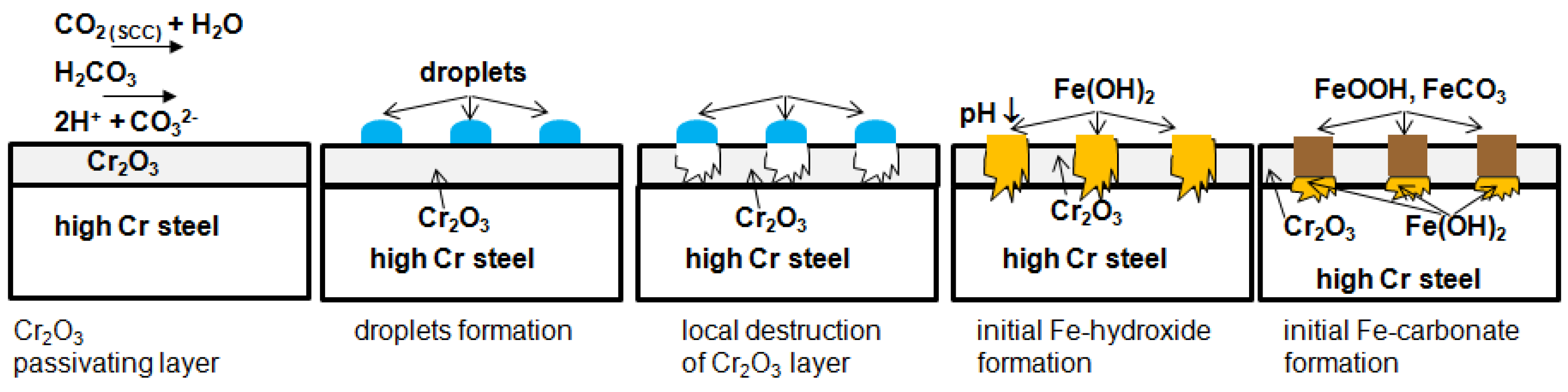
The passivating layer is locally destroyed, possibly due to locally very low pH as a consequence of the formation of carbonic acid in water-saturated supercritical CO2 leading to anodic dissolution.
(b)
The carbide distribution within the steels’ microstructure is not homogeneous. Carbides located at the metal surface corrode locally because carbides are more susceptible to anodic dissolution [20]. Consequently, ellipsoids grow from the initial carbide dissolution leaving a newly exposed metal surface that is highly susceptible to the corrosive environment.
(c)
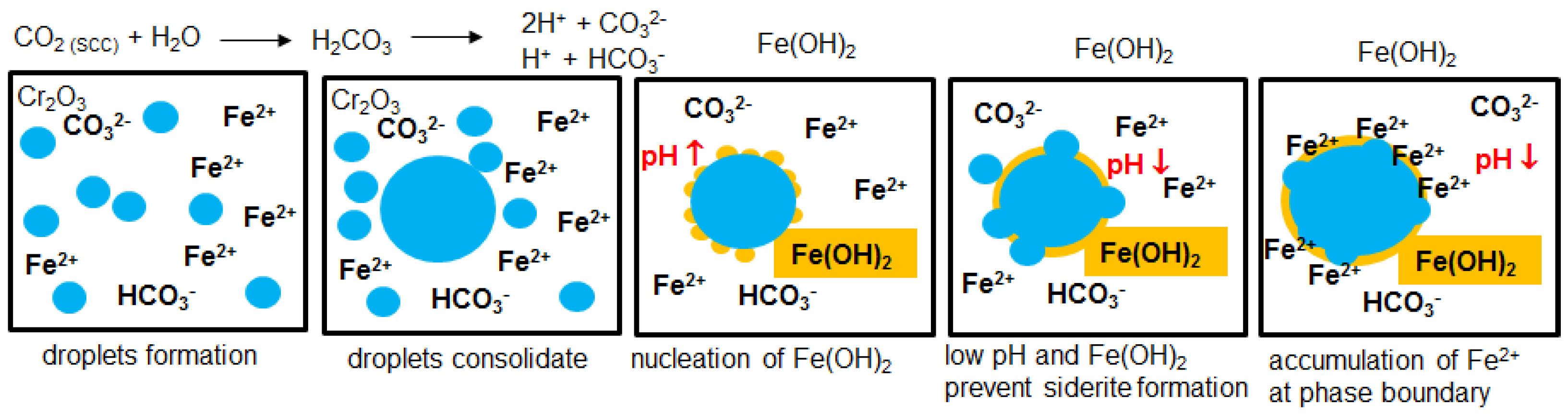
Carbonic acid H2CO3 (as a reaction product from water and CO2) is not soluted equally along the entire sample surfaces. Hence, a thin passivating layer is formed in the initial corrosion stage that then starts growing locally. Once a sufficient thickness of these corrosion islands is achieved, it detaches laterally, causing corrosion reactions.
(d)
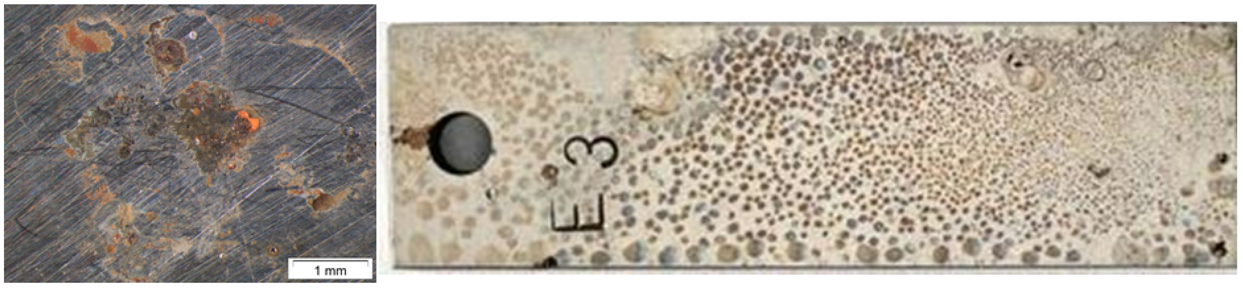
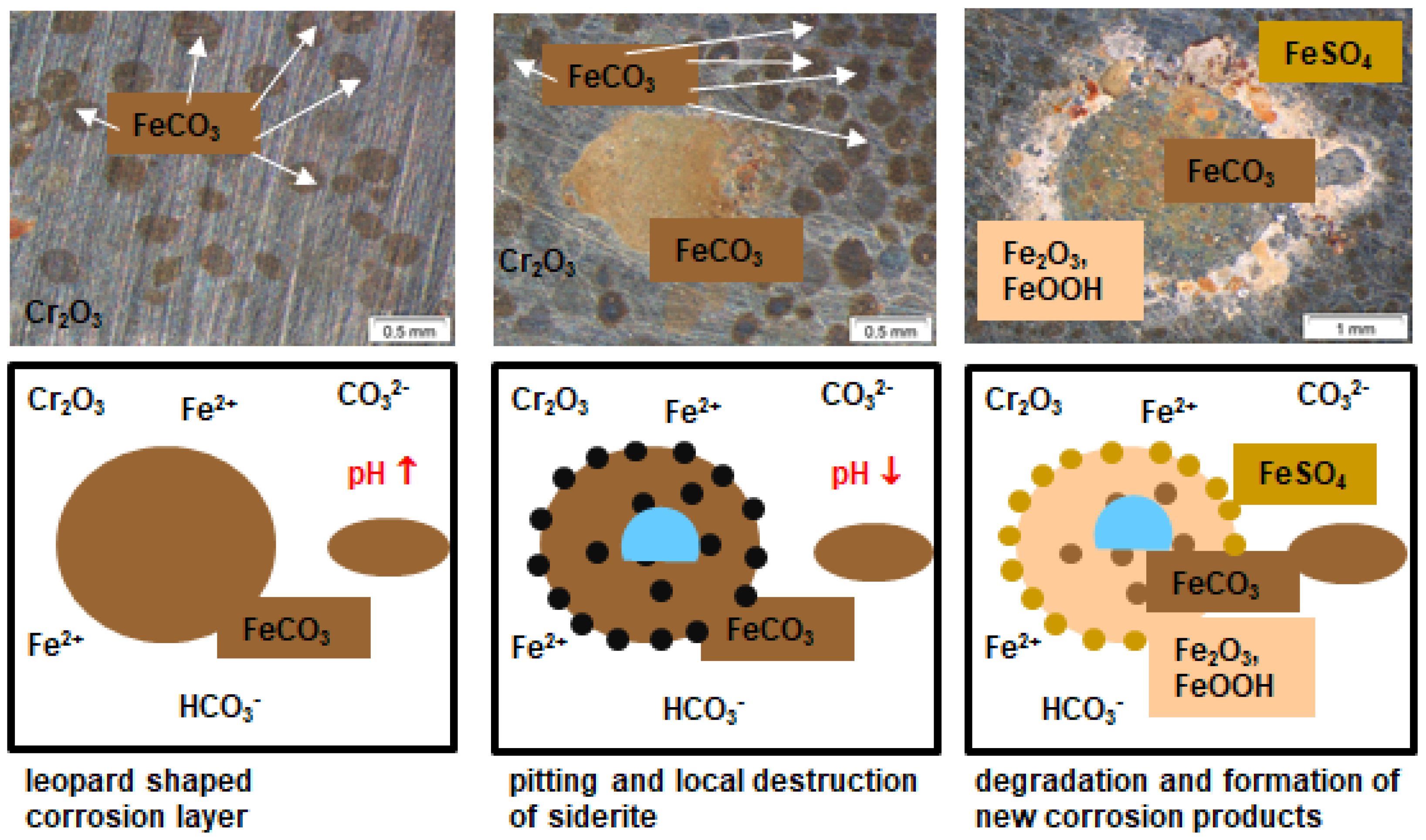
In general, raising the temperature accelerates the water solubility in supercritical CO2. Choi et al. reported that the solubility of water in CO2 decreases in the region 0 bar—50 bar and then slightly raises again [62]. Because the temperature was kept constant (60 °C) and the pressure was at a constant 100 bar, both, neither the temperature nor pressure influence the solubility of water in supercritical CO2 over time. Furthermore, in this particular CCS environment, the solubility decreases overall. Consequently, at 100 bar and 60 °C, the metal surface that precipitated a passivating layer consisting of Cr2O3 and (Fex(Cr1−x))3O4 is wetted by very thin and small water droplets. Distinct “leopard”-shaped corrosion layers form associated with initial droplets condensed on the surface. The residual water droplets can be seen in Figure 8, with bigger droplets in the middle and the small former droplets now being the “leopard” ellipsoids. At the metal–water–supercritical CO2 phase boundary, the surface is locally depassivated, whereas the remaining surface is covered by thin passivating corrosion layers. This formation model will be described in detail below.
Note that even this unusual corrosion behaviour gives very low surface corrosion rates (<0.01 mm/year) for both steels. Therefore, ellipsoids and surrounding surfaces passivate the steel surfaces and prevent the metal from early degradation. Pitting is not taken into account here; the centres of the bigger droplets reveal pits (Figure 8), indicating that the passivating nature of the ellipsoids is highly dependent on their size.

3.4. Formation Mechanism in Water Saturated Supercritical CO2 (SCC)

Contrary to our findings in Figure 2 and Figure 3, Hassani et al. [63] found higher corrosion rates in supercritical CO2 (in this study, this only accounts for pit corrosion [42]). They stated that the corrosion mechanisms in supercritical CO2 as well as gaseous CO2 are the same deriving from polarization curves [63]. Wei et al. [64] also state that the corrosion mechanisms at high pressure (supercritical CO2 in liquid phase) are similar to those obtained at ambient pressure with low CO2 partial pressure (liquid phase). This is contradicted by Liu et al. [65] who explain the difference of corrosion mechanism in water-saturated CO2 and CO2-saturated water by the distance of water chemistry.
A higher corrosion rate is mainly explained through increasing CO2 partial pressure [9,15,16,17,32,34,41,49,51,52,58,59], resulting in a more acidic and reactive environment and more initially formed carbonic acid H2CO3, dissociating to H3O+ and HCO3 according to Equation (5). However, here the unusual corrosion pattern may contribute to the low corrosion rates in supercritical CO2 saturated with aquifer water according to a geothermal CCS site.
The high chromium steel is passivated by Cr2O3 and (Fex(Cr1−x))3O4 before being in contact with the CCS environment (Equation (2)).
4Cr + 3O2 → 2 Cr2O3
Long exposure hours lead to high surface corrosion rates in the supercritical phase after 1000 h of exposure because the passivating layer decays exposing the newly formed metal surface to an electrolyte with high CO2 partial pressure. As a consequence, after long exposure times, the base metal microstructure decomposes and internal corrosion processes accelerate in water-saturated supercritical CO2.
Once the supercritical CO2 (SCC) is saturated with water, droplets are formed on the metal surface due to the low solubility of water in SCC [62], even decreasing with time in this particular CCS environment, as described above. Here, carbonic acid H2CO3 is formed quickly, according to Equations (3) and (4):
H2O → H+ + OH
CO2 (SCC) + H2O (l) → H2CO3
The cathodic reaction in the CO2 corrosion process is driven by the formation of HCO3, depending on the exchange of ionic species described in Equation (5), and by the CO2 partial pressure in the encircling medium, leading to an increasing H2CO3 concentration [10,26]. The cathodic reactions consist of the reduction of H2CO3, HCO3 (aq) and H+ (Equations (4–6)).
Cathodic reactions:
H2CO3 + e → H+ + HCO3 (aq)
H2CO3 + H2O → H3O+ + HCO3
2 HCO3 (aq) + 2 e → 2 CO32 + H2
2 H+ + 2 e → H2
According to Nesic et al. [3], the corrosion rate increases as the partial pressure of CO2 increases for scale-free CO2 corrosion processes. The environment becomes more acidic and reactive as a result of higher partial pressure of the CO2 in the water-saturated supercritical CO2 phase. It is well accepted that the concentration of carbonic acid H2CO3 increases with increasing CO2 partial pressure that accelerate the cathodic reactions, consequently resulting in higher corrosion rates.
In the CO2 corrosion process, the anodic reaction comprises of the dissolution of Fe (Equation (8) in the case of local depassivation or destruction of the C2O3 or Fex(Cr1−x))3O4 layer. After the CO2 is dissipated to establish a corrosive environment (carbonic acid H2CO3), iron from the base metal is dissolved in the acidic water droplet. Because the solubility of FeCO3 in water is low (pKsp = 10.54 at 25 °C) [26,43] a siderite FeCO3 corrosion layer expands on the alloy surface in the wake of the anodic iron dissolution [13,16,19,20,21], according to Equations (10)–(12) (Figure 9).
Anodic reactions:
Fe → Fe2+ + 2e
Fe2+ + CO32 → FeCO3
Fe2+ + 2 HCO3 → Fe(HCO3)2
Fe(HCO3)2 → FeCO3 + CO2 + H2O
These reactions were discussed in detail by various authors [6,9]. CO2 corrosion is mainly driven by the generation of carbonic acid and the existence of HCO3 [17]. According to Han et al. [66] and Wei et al. [64], the corrosion takes place in a two-step reaction where an amorphous phase explains differences in the porous structure of the inner and outer layer of the corrosion layer. In the first stage, the steel is introduced to the corrosive environment, the water-saturated supercritical CO2 (SCC). As soon as the solubility limit of water in SCC is exceeded, water droplets form on the steels’ surface and the carbon dioxide forms carbonic acid H2CO3 within the droplets. An initial reaction step may be ascribed to the formation of Fe[II] compounds Fe(OH)2 (Equation (13)), an amorphous metastable transient ferrous hydroxide passivating film [6,26], when Fe(OH)2 exceeds its solubility limit. At the same time, the local pH near the hydroxide film increases locally (Figure 10 and Figure 11).
Fe + 2H2O → [Fe(OH)2] amorph + 2H+ + 2e
Wei et al. [64] found that independent of the pressure, the CO32− concentration was similar at high pressure and ambient pressure, but the pH in the liquid phases was much higher at high pressure. This also accounts for the initial water droplets forming on the steels’ surface in supercritical water-saturated CO2 and may be the result of the formation of the transient Fe(OH)2 layer from the water droplet and not from SCC. Soon after the ferrous hydroxide is formed, the surrounding pH decreases again at high pressure, when it is exposed to fresh water-saturated SCC containing carbonic acid from the growing droplet. With pH being as low as 4.5, the solubility of siderite FeCO3 increases, supersaturating the water droplets with CO32−, H3O+ and HCO3 ions during the corrosion initiation period. As a consequence of the enhanced solubility of FeCO3, the formation of a stable solid carbonate layer is impeded.
Additionally, because crystal growth is the dominating reaction at low supersaturation—nucleation dominates at high supersaturation [64]—crystal growth of siderite FeCO3 is also prevented, leaving a transient nanocrystalline or amorphous hydroxide scale [6,17,26] on the steels’ surface, according to Equation (13). In this initiation period, no continuous scale is formed in the CO2-saturated droplet leading to the first decomposing reactions on the steel’s surface. The formation of the amorphous or nanocrystalline scale prior to siderite precipitation reduces the corrosion rate and consequently, the concentration of iron ions Fe+. Furthermore, it blocks the mutual diffusion of ionic species Fe+, CO32− and O2− at the metal/amorphous phase boundary. Here the accumulation of Fe+ species at the base metal–hydroxide interface favours reactions, according to a second reaction step (Equation (14)).
At the same time, the increased formation rate of Fe2+ ions (Equation (9) enhances carbide precipitation close to the hydroxide/metal boundary at the metals’ surface (Figure 10). Carbides are not only more susceptible to decomposing reactions they also affect the scale growth mechanism [64]. Growth of the carbonate layer will proceed internally and externally depending on the various carbon and oxygen partial pressures.
The following step refers to goethite FeOOH and siderite FeCO3 formation when carbon dioxide CO2 and water consequently form when carbonic acid H2CO3 is present (Figure 11). FeCO3 and goethite α-FeOOH not only result from a rather low pH in CO2-containing and its low solubility [26]; it may also form as a result from further reactions of the transient ferrous hydroxide phase.
[Fe(OH)2] (aq) + H2O → α-FeOOHtrans + 3H+ + 3e
[Fe(OH)2] (aq) + [H2CO3] (aq) → FeCO3 + 2H2O
The more acidic environment then leads to the complete formation of a discontinuous ferrous carbonate film in the area of former droplets, according to Equations (14) and (15). This is visible as centres of the ellipsoids after exposure to CCS environment. At high pressure with low CO2 supersaturation, as found in the CO2-saturated droplet phase, reactions kinetics are much slower than in SCC. Therefore, nucleation reactions are slow and stable crystal growth of siderite is then the dominating reaction mechanism. A stable and dense siderite layer is formed within the area of the droplets. The now passivating ellipsoids are surrounded by the passivating C2O3 layer giving low corrosion rates as stated in Figure 3.
When metastable hydroxides form before siderite precipitates the local arrangement of the phases at equilibration is changed [6]. The hydroxide/brine interface absorbs carbonate ions which react with oxygen vacancies and develop cation/oxygen vacancy pairs of the Mott–Schottky-type. At the same time, oxygen vacancies at the hydroxide/brine interface react in reverse with additional carbonate ions to form additional cation vacancies. The excess vacancies move and attach to the hydroxide/siderite interface, where they condense. As a negative result, the siderite detaches from the transient hydroxide film-enabling surface degradation and particularly pitting. However, after a long exposure time (8000 h), mechanical failure is assumed as well because of the different surface morphologies and because the thermal expansion coefficients most likely do not match. If a critical thickness is exceeded, the corrosion layer consequently detaches in a lateral direction [6,16,41].

3.5. Degradation of Carbonate and Hydroxide Layer

As mentioned before, the typical “leopard”-shaped corrosion layer forms, which indicates the initial small droplets on the metal surface. These grow in diameter with increasing exposure time. Here the surface is depassivated locally; first ferrous hydroxide was formed, then siderite FeCO3 nucleated to build a passivating layer. Both reactions driven from HCO3 and CO32− as well as a reaction via the amorphous/nanocrystalline transient Fe(OH)2 take place. The resulting siderite is visible as darker ellipsoids in a grey-coloured metal surface (Figure 1, Figure 6, Figure 7 and Figure 8). The remaining surface is covered by a thin passivating corrosion Cr2O3 layer. As a function of exposure time, new droplets condense on the metal surface, causing the pH to decrease (note, the precipitation of ferrous hydroxide causes an increase of pH, leading to a stable transient hydroxide layer). These droplets consolidate building a three-phase boundary (water, metal, SCC supercritical CO2) at the outer area. The centres of the bigger droplets reveal pits, indicating that the passivating nature of the ellipsoids is highly dependent on their size. Once a critical size is exceeded, pitting is initiated (explaining the rather high number of pits precipitated on both steel qualities [41,42,51]). Degradation of the base material is initiated at the three-phase boundary because the thin passivating siderite FeCO3 layer is destroyed locally (Figure 12). At the same time, the base metal is decomposed within the diameter of the condensed water droplets, whereas the outer regions remain covered by the Cr2O3 layer. Small pits surrounding the former droplet precipitate at the multiphase boundary as well as in the droplets’ interior enhancing the corrosion processes (Figure 12). The flowing corrosive media removes the remaining film, causing the pit to grow wider and eventually cover larger parts of the surface. Because it takes much more time for pits to consolidate and grow wider than new droplets to form, water diffuses back into the supercritical CO2. The consolidated droplets decrease inwards in size and reduce in total area (in which the siderite FeCO3 is decomposed), leaving sulphates (FeSO4) in the outer areas, whereas the centre shows goethite α-FeOOH as well as hematite Fe2O3 [16,51,52] as a result from oxidation reaction after the test periods.

4. Conclusions

The formation mechanism for elliptical corrosion layers on X35CrMo17 and X5CrNiCuNb16-4 exposed to a laboratory CCS atmosphere similar to the Northern German Basin was outlined and the assumed reaction mechanism was described. The corrosion scale is characterized by a “leopard”-shaped corrosion scale. Therefore, coupons of the steel quality X35CrMo17 and X5CrNiCuNb16-4 suitable as injection pipe with 17% and 16% Chromium were exposed up to approximately one year (8000 h) to supercritical CO2 and saline aquifer water at 100 bar and 60 °C in laboratory experiments.
Both steel qualities passivate leading to the low surface corrosion rates on both steels (<0.012 mm/year). Due to excess oxygen in the open test circuit at ambient pressure, corrosion rates at ambient pressure exceed those measured after exposure at 100 bar by a factor of 50. In general, higher pressure induces pitting (pit per m2). However, especially at 100 bar, the corrosion kinetics of X35CrMo17 are slower (max. 0.007 mm/year) compared to steel qualities 42CrMo4, X20Cr13, X46Cr13 and X5CrNiCuNb16-4 independent of the environment (water-saturated supercritical CO2 or CO2-saturated saline aquifer water). If the passivating FeOOH, α-FeCO3 layer degrades severely, pitting corrosion is initiated, which results in ongoing local degradation of the base metal in a CCS environment.
At high pressure, a non-uniform corrosion layer (“leopard” shape) reveals products from carbonate corrosion on the surface comprising of α-FeCO3 and FeOOH and more possibly Cr2(CO3)3 and CrOOH due to the high chromium content. Inside the typical ellipsoids, Fe2O3 and Cr2O3 precipitate due to altering water solubility in supercritical CO2 at high pressure and the dominating reaction mechanism changes from nucleation to crystal growth. It is assumed that in this particular CCS environment, the solubility of water in supercritical CO2 decreases overall. Consequently, at 100 bar and 60 °C, the metal surface originally covered by a passivating layer consisting of Cr2O3 and (Fex(Cr1−x))3O4 is wetted by very thin and small water droplets. The peculiar “leopard”-shaped corrosion layer is associated with these initial droplets on the surface. At the metal–water-supercritical CO2 phase boundary, the surface is locally depassivated, whereas the remaining surface is covered by thin passivating corrosion layers. As a function of exposure time, regions of earlier droplets consolidate with former outer areas corroding the most at the three-phase boundary: metal–water–SCC. Small pits precipitate enhancing the corrosion processes. Because it takes more time for pits to consolidate than new droplets to form, the reverse process starts with water diffusing back into the supercritical CO2, where it reduces the region of consolidated droplets from the outer area towards the centre. Consequently, sulphates (FeSO4) remain in the outer areas whereas the centres show hematite Fe2O3 and goethite α-FeOOH.
Local corrosion is especially crucial in the decision process for suitable steels in CCS application. Steels are inoperable in pressure vessel applications if the surface corrosion rate exceeds 0.1 mm/year. Because X35CrMo17 and also X5CrNiCuNb16-4 stay way below this margin at high pressure, it may be considered safe in terms of surface corrosion. However, pitting corrosion—as an almost unpredictable statistical phenomenon—is not admitted in order to fulfil the regulations of DIN 6601 due to a rather high risk of notch effects on the surface. Notches may be the cause of fractures and the following failure of the component. Therefore, predicting the lifetime of steels susceptible to pit corrosion in CCS environment is not possible according to this study.
This paper comprises and compares data of previously published work: [9,15,17,32,34,41,42,49,50,51,52,53,58,59,60].

Author Contributions

Conceptualization, A.P.; methodology, A.P.; software, validation, A.P., A.K.; formal analysis, A.P.; investigation, A.P.; resources, A.P., A.K.; data curation, A.P.; writing—original draft preparation, A.P.; writing—review and editing, A.P.; visualization, A.P.; supervision, A.P. and A.K.; project administration, A.P.; funding acquisition, A.P. All authors have read and agreed to the published version of the manuscript.

Funding

This research received no external funding.

Institutional Review Board Statement

Not applicable.

Informed Consent Statement

Not applicable.

Conflicts of Interest

The authors declare no conflict of interest.

References

  1. Thomas, C. Carbon Dioxide Capture for Storage in Deep Geologic Formations—Results from CO2 Capture Project; Elsevier Ltd.: London, UK, 2005; ISBN 0080445748. [Google Scholar]
  2. Broek, M.V.D.; Hoefnagels, R.; Rubin, E.; Turkenburg, W.; Faaij, A. Effects of technological learning on future cost and performance of power plants with CO2 capture. Prog. Energy Combust. Sci. 2009, 35, 457–480. [Google Scholar] [CrossRef]
  3. Nešić, S. Key issues related to modelling of internal corrosion of oil and gas pipelines—A review. Corros. Sci. 2007, 49, 4308–4338. [Google Scholar] [CrossRef]
  4. Hurter, S. Impact of Mutual Solubility of H2O and CO2 on Injection Operations for Geological Storage of CO2. In Proceedings of the International Conference of the Properties of Water and Steam ICPWS, Berlin, Germany, 8–11 September 2012. [Google Scholar]
  5. Zhang, L.; Yang, J.; Sun, J.S.; Lu, M. Effect of pressure on wet H2S/CO2 corrosion of pipeline steel. In Proceedings of the NACE Corrosion 2008 Conference and Expo, New Orleans, LA, USA, 16–20 March 2008. Paper No. 09565. [Google Scholar]
  6. Mu, L.J.; Zhao, W.Z. Investigation on Carbon Dioxide Corrosion Behaviors of 13Cr Stainless Steel in Simulated Strum Water. Corros. Sci. 2010, 2, 82–89. [Google Scholar] [CrossRef]
  7. Seiersten, M. Material selection for separation, transportation and disposal of CO2. In NACE International, Houston, CORROSION/2001; Paper No. 01042; NACE International: Houston, TX, USA, 2001. [Google Scholar]
  8. Cui, Z.D.; Wu, S.L.; Zhu, S.L.; Yang, X.J. Study on corrosion properties of pipelines in simulated produced water saturat-ed with supercritical CO2. Appl. Surf. Sci. 2006, 252, 2368–2374. [Google Scholar] [CrossRef]
  9. Pfennig, A.; Kranzmann, A. Reliability of pipe steels with different amounts of C and Cr during onshore carbon dioxide injection. Int. J. Greenh. Gas Control 2011, 5, 757–769. [Google Scholar]
  10. Zhang, H.; Zhao, Y.L.; Jiang, Z.D. Effects of temperature on the corrosion behavior of 13Cr martensitic stainless steel dur-ing exposure to CO2 and Cl environment. Mater. Lett. 2005, 59, 3370–3374. [Google Scholar] [CrossRef]
  11. Alhajji, J.; Reda, M. The effect of alloying elements on the electrochemical corrosion of low residual carbon steels in stagnant CO2-saturated brine. Corros. Sci. 1993, 34, 1899–1911. [Google Scholar] [CrossRef]
  12. Choi, Y.-S.; Nešić, S. Corrosion behavior of carbon steel in supercritical CO2-water environments. In Proceedings of the NACE Corrosion 2008 Conference and Expo, New Orleans, LA, USA, 16–20 March 2008. Paper No. 09256. [Google Scholar]
  13. Jiang, X.; Nešić, S.; Huet, F. The Effect of Electrode Size on Electrochemical Noise Measurements and the Role of Chloride on Localized CO2 Corrosion of Mild Steel. In Proceedings of the NACE Corrosion 2008 Conference and Expo, New Orleans, LA, USA, 16–20 March 2008; p. 09575. [Google Scholar]
  14. Ahmad, Z.; Allam, I.M.; Abdul, B.; Aleem, J. Effect of environmental factors on the atmospheric corrosion of mild steel in aggressive sea coastal environment. Anti Corros. Methods Mater. 2000, 47, 215–225. [Google Scholar] [CrossRef]
  15. Pfennig, A.L.; Bäßler, R. Effect of CO2 on the stability of steels with 1% and 13% Cr in saline water. Corros. Sci. 2009, 51, 931–940. [Google Scholar] [CrossRef]
  16. Pfennig, A.; Wolf, M.; Kranzmann, A. Corrosion and Corrosion Fatigue of Steels in Downhole CCS Environment-A Summary. Processes 2021, 9, 594. [Google Scholar] [CrossRef]
  17. Pfennig, A.; Zastrow, P.; Kranzmann, A. Influence of heat treatment on the corrosion behavior of stainless steels during CO2-sequestration into saline aquifer. Int. J. Greenh. Gas Control 2013, 15, 213–224. [Google Scholar] [CrossRef]
  18. Nyborg, R. Controlling Internal Corrosion in Oil and Gas Pipelines. Business Briefing: Exploration & Production. Oil Gas Rev. 2005, 2, 70–74. [Google Scholar]
  19. Carvalho, D.S.; Joia, C.; Mattos, O. Corrosion rate of iron and iron–chromium alloys in CO2 medium. Corros. Sci. 2005, 47, 2974–2986. [Google Scholar] [CrossRef]
  20. Linter, B.R.; Burstein, G.T. Reactions of pipeline steels in carbon dioxide solutions. Corros. Sci. 1999, 41, 117–139. [Google Scholar] [CrossRef]
  21. Wu, S.L.; Cui, Z.D.; Zhao, G.X.; Yan, M.L.; Zhu, S.L.; Yang, X.J. EIS study of the surface film on the surface of carbon steel form supercritical carbon dioxide corrosion. Appl. Surf. Sci. 2004, 228, 17–25. [Google Scholar] [CrossRef]
  22. Bülbül, Ş.; Sun, Y. Corrosion behavior of high Cr-Ni cast steels in the HCl solution. J. Alloys Compd. 2010, 598, 143–147. [Google Scholar] [CrossRef]
  23. Hou, B.; Li, Y.; Li, Y.; Zhang, J. Effect of alloy elements on the anti-corrosion properties of low alloy steel. Bull. Mater. Sci 2000, 23, 189–192. [Google Scholar] [CrossRef]
  24. Cvijović, Z.; Radenković, G. Microstructure and pitting corrosion resistance of annealed duplex stainless steel. Corros. Sci. 2006, 48, 3887–3906. [Google Scholar] [CrossRef]
  25. Park, J.-Y.; Park, Y.-S. The effects of heat-treatment parameters on corrosion resistance and phase transformations of 14Cr–3Mo martensitic stainless steel. Mater. Sci. Eng. A 2007, 449–451, 1131–1134. [Google Scholar] [CrossRef]
  26. Banaś, J.; Lelek-Borkowska, U.; Mazurkiewicz, B.; Solarski, W. Effect of CO2 and H2S on the composition and stability of passive film on iron alloys in geothermal water. Electrochim. Acta 2007, 52, 5704–5714. [Google Scholar] [CrossRef]
  27. Bilmes, P.; Llorente, C.; Méndez, C.; Gervasi, C. Microstructure, heat treatment and pitting corrosion of 13CrNiMo plate and weld metals. Corros. Sci. 2009, 51, 876–881. [Google Scholar] [CrossRef]
  28. Zhang, L.; Zhang, W.; Jiang, Y.; Deng, B.; Sun, D.; Li, J. Influence of annealing treatment on the corrosion resistance of lean duplex stainless steel 2101. Electrochimica Acta 2009, 54, 5387–5392. [Google Scholar] [CrossRef]
  29. Brown, B.; Parakala, S.R.; Nešić, S. CO2 corrosion in the presence of trace amounts of H2S. In Proceedings of the NACE International Corrosion Conference Series: Corrosion 2004, New Orleans, LA, USA, 28 March–1 April 2004. Paper No. 04736. [Google Scholar]
  30. Isfahany, A.N.; Saghafian, H.; Borhani, G. The effect of heat treatment on mechanical properties and corrosion behavior of AISI420 martensitic stainless steel. J. Alloys Compd. 2011, 509, 3931–3936. [Google Scholar] [CrossRef]
  31. Lucio-Garcia, M.; Gonzalez-Rodriguez, J.; Casales, M.; Martinez, L.; Chacon-Nava, J.; Neri-Flores, M.; Martinez-Villafañe, A. Effect of heat treatment on H2S corrosion of a micro-alloyed C–Mn steel. Corros. Sci. 2009, 51, 2380–2386. [Google Scholar] [CrossRef]
  32. Pfennig, A.; Wolthusen, H.; Wolf, M.; Kranzmann, A. Effect of heat Treatment of Injection Pipe Steels on the Reliability of a Saline Aquifer Water CCS-site in the Northern German Basin. Energy Procedia 2014, 63, 5762–5772. [Google Scholar] [CrossRef] [Green Version]
  33. Thorbjörnsson, I. Corrosion fatigue testing of eight different steels in an Icelandic geothermal environment. Mater. Des. 1995, 16, 97–102. [Google Scholar] [CrossRef]
  34. Pfennig, A.; Kranzmann, A. Borehole Integrity of Austenitized and Annealed Pipe Steels Suitable for Carbon Capture and Storage (CCS). Int. J. Mater. Mech. Manuf. 2017, 5, 213–218. [Google Scholar] [CrossRef] [Green Version]
  35. Maranhão, J.P. Davim, finite element modelling of machining of AISI 316steel: Numerical simulation and experimental validation. Simul. Modell. Pract. Theory 2010, 18, 139–156. [Google Scholar]
  36. Martin, M.; Weber, S.; Izawa, C.; Wagner, S.; Pundt, A.; Theisen, W. Influence of machining-induced martensite on hydrogen-assisted fracture of AISI type 304 austenitic stainless steel. Int. J. Hydrog. Energy 2011, 36, 11195–11206. [Google Scholar] [CrossRef]
  37. Evgenya, B.; Hughesa, T.; Eskinba, D. Effect of surface roughness on corrosion behavior of low carbon steelin inhibited 4 M hydrochloric acid under laminar and turbulent flow conditions. Corros. Sci. 2016, 103, 196–205. [Google Scholar] [CrossRef]
  38. Xu, M.; Zhang, Q.; Yang, X.X.; Wanga, Z.J.; Liub, J.; Li, Z. Impact of surface roughness and humidity on X70 steel corrosion in supercritical CO2mixture with SO2, H2O, and O2. J. Supercrit. Fluids 2016, 107, 286–297. [Google Scholar] [CrossRef]
  39. Llaneza, V.; Belzunce, F.J. Study of the effects produced by shot peening on the surface of quenched and tempered steels: Roughness, residual stresses and work. Appl. Surf. Sci. 2015, 356, 475–485. [Google Scholar] [CrossRef]
  40. Lee, S.M.; Lee, W.G.; Kim, Y.H.; Jang, H. Surface roughness and the corrosion resistance of 21Cr ferritic stainless steel. Corros. Sci. 2012, 63, 404–409. [Google Scholar] [CrossRef]
  41. Pfennig, A.; Kranzmann, A. Effect of CO2 and pressure on the stability of steels with different amounts of chromium in saline water. Corros. Sci. 2012, 65, 441–452. [Google Scholar] [CrossRef]
  42. Pfennig, A.; Kranzmann, A. Effect of CO2, Atmosphere and Pressure on the Stability of X35CrMo17 Stainless Steel in Laboratory CCS-Environment. In Proceedings of the 14th Greenhouse Gas Control Technologies Conference, Melbourne, VIC, Australia, 21–26 October 2018. [Google Scholar]
  43. Lopez, D.A.; Schreiner, W.H.; de Sánchez, S.R.; Simison, S.N. The influence of carbon steel microstructure on corrosion layers an XRS and SEM characterization. Appl. Surf. Sci. 2003, 207, 69–85. [Google Scholar] [CrossRef]
  44. Akbari Mousavi, S.A.A.; Sufizadeh, A.R. Metallurgical investigations of pulsed Nd:YAG laser welding of AISI 321 and AISI 630 stainless steels. Mater. Des. 2009, 30, 3150–3157. [Google Scholar] [CrossRef]
  45. Takemoto, M. Study on the Failure Threshold Stress Criteria for the Prevention and Mechanism of Stress Corrosion Cracking; Faculty of Science and Engineering, Aoyama Gakuin University: Tokyo, Japan, 1984. [Google Scholar]
  46. Nor Asma, R.B.A.; Yuli, P.A.; Mokhtar, C.I. Study on the effect of surface finish on corrosion of carbon steel in CO2 environment. J. Appl. Sci. 2011, 11, 2053–2057. [Google Scholar] [CrossRef] [Green Version]
  47. Wang, J.; Zou, H. Relationship of microstructure transformation and hardening behavior of type 630 stainless steel. J. Univ. Sci. Technol. Beijing 2006, 3, 213–221. [Google Scholar] [CrossRef]
  48. Islam, A.W.; Sun, A.Y. Corrosion model of CO2 injection based on non-isothermal wellbore hydraulics. Int. J. Greenh. Gas Control 2016, 54, 219–227. [Google Scholar] [CrossRef] [Green Version]
  49. Pfennig, A.; Wolthusen, H.; Zastrow, P.; Kranzmann, A. Evaluation of heat treatment performance of potential pipe steels in CCS-environment. In Energy Technology 2015: Carbon Dioxide Management and Other Technologies; Springer International Publishing: Berlin/Heidelberg, Germany, 2016; pp. 15–22. [Google Scholar] [CrossRef]
  50. Pfennig, A.; Trenner, S.; Wolf, M.; Bork, C. Vibration Tests for Determination of Mechanical Behavior in CO2-Containing Solutions in European Corrosion Congress EuroCorr 2013; Estoril Congress Center: Estoril, Portugal, 2013. [Google Scholar]
  51. Pfennig, A.; Wolthusen, H.; Kranzmann, A. Unusual Corrosion Behavior of 1.4542 Exposed a Laboratory Saline Aquifer Water CCS-environment. Energy Procedia 2017, 114, 5229–5240. [Google Scholar] [CrossRef]
  52. Pfennig, A.; Kranzmann, A. Potential of martensitic stainless steel X5CrNiCuNb 16-4 as pipe steel in corrosive CCS environment. Int. J. Environ. Sci. Dev. 2017, 8, 466–473. [Google Scholar] [CrossRef] [Green Version]
  53. Pfennig, A.; Kranzmann, A. Corrosion and Fatigue of Heat Treated Martensitic Stainless Steel 14542 Used For Geothermal Applications. Matter Int. J. Sci. Technol. 2019, 5, 138–158. [Google Scholar] [CrossRef]
  54. Han, J.; Yang, Y.; Nešić, S.; Brown, N.B. Roles of passivation and galvanic effects in localized CO2 corrosion of mild steel. In Proceedings of the NACE Corrosion 2008, New Orleans, LA, USA, 16–20 March 2008. Paper No. 08332. [Google Scholar]
  55. Förster, A.; Norden, B.; Zinck-Jørgensen, K.; Frykman, P.; Kulenkampff, J.; Spangenberg, E.; Erzinger, J.; Zimmer, M.; Kopp, J.; Borm, G.; et al. Baseline characterization of the CO2SINK geological storage site at Ketzin, Germany. Environ. Geosci. 2006, 13, 145–161. [Google Scholar] [CrossRef]
  56. Forster, A.; Schoner, R.; Förster, H.-J.; Norden, B.; Blaschke, A.-W.; Luckert, J.; Beutler, G.; Gaupp, R.; Rhede, D. Reservoir characterization of a CO2 storage aquifer: The Upper Triassic Stuttgart Formation in the Northeast German Basin. Mar. Pet. Geol. 2010, 27, 2156–2172. [Google Scholar] [CrossRef]
  57. Bäßler, R.; Sobetzki, J.; Klapper, H.S. Corrosion Resistance of High-Alloyed Materials in Artificial Geothermal Fluids. In Proceedings of the NACE International Corrosion Conference Series: Corrosion 2013, New Orleans, LA, USA, 17–21 March 2013. Paper No. 2327. [Google Scholar]
  58. Pfennig, A.; Wolf, M. Influence of geothermal environment on the corrosion fatigue behavior of standard duplex stainless steel X2CrNiMoN22-5-32. J. Phys. Conf. Ser. 2020, 1425, 012183. [Google Scholar]
  59. Pfennig, A.; Wolf, M.; Kranzmann, A. Evaluating corrosion and corrosion fatigue behavior via laboratory testing techniques in highly corrosive CCS-environment. In Proceedings of the 15th Greenhouse Gas Control Technologies Conference 2020, Abu Dhabi, United Arab Emirates, 15–18 March 2021. [Google Scholar]
  60. Pfennig, A.; Wolf, M.; Kranzmann, A. Effects of saline aquifer water on the corrosion behavior of martensitic stainless steels during exposure to CO2 environment. In Proceedings of the 15th Greenhouse Gas Control Technologies Conference 2020, Abu Dhabi, United Arab Emirates, 15–18 March 2021. [Google Scholar]
  61. Kraus, S.W.; Nolze, G. POWDER CELL—A program for the representation and manipulation of crystal structures and calculation of the resulting X-ray powder patterns. J. Appl. Cryst. 1996, 29, 301–303. [Google Scholar] [CrossRef]
  62. Choi, Y.-Y.; Nešić, S. Determining the corrosive potential of CO2 transport pipline in high pCO2-water environments. Int. J. Greenh. Gas Control 2011, 5, 788–797. [Google Scholar] [CrossRef]
  63. Hassani, S.; Vu, T.N.; Rosli, N.R.; Esmaeely, S.N.; Choi, Y.S.; Young, D.; Nešić, S. Wellbore integrinanoty and corrosion of low alloy steel and stainless steels in high pressure CO2 geologic storage environment: An experimental study. Int. J. Greenh. Gas Control 2014, 23, 594–601. [Google Scholar] [CrossRef]
  64. Wei, L.; Pang, X.; Liu, C.; Gao, K. Formation mechanism and protective property of corrosion product scale on X70 steel under supercritical CO2 environment. Corros. Sci. 2015, 100, 404–420. [Google Scholar] [CrossRef]
  65. Liu, Z.-G.; Gao, S.-H.; Du, S.-X.; Li, J.-P.; Yu, C.; Wang, Y.-X.; Wang, X.-N. Comparison of corrosion mechanism of low alloy pipeline steel used for flexible pipes at vapor-saturated CO2 and CO2-saturated brine conditions. Mater. Corros. 2017, 68, 1200–1211. [Google Scholar] [CrossRef]
  66. Han, J.; Zhang, J.; Carey, J.W. Effect of bicarbonate on corrosion of carbon steel in CO2-saturated brines. Int. J. Greenh. Gas Control 2011, 5, 1680–1683. [Google Scholar] [CrossRef]
Figure 1. Left: SEM micrographs (8000 h at 60 °C/100 bar exposed to water-saturated supercritical CO2) of the corrosion layer formed on X5CrNiCuNb16-4 with ellipsoidal peculiarity on hardened and tempered at 670 °C. Reprintetd with permission from [16]. 2021 MDPI, A. Pfennig.
Cleantechnol 04 00014 g001
Figure 2. Comparison of corrosion rates of X35CrMo17 to X20Cr13, X46Cr13, 42CrMo4 and X5CrNiCuNb16-4 exposed to liquid and vapour/supercritical CO2-saturated geothermal environment at ambient pressure (left) and 100 bar (right) after exposure for 8000 h to aquifer brine water at 60 °C. Results were taken from [9,15,16,17,42] and combined.
Cleantechnol 04 00014 g002
Figure 3. Arrangement of corrosion rates of X35CrMo17 to X20Cr13, X46Cr13, 42CrMo4 and X5CrNiCuNb16-4 with regard to atmosphere: the liquid, intermediate, vapor/supercritical phase at ambient pressure (left) and 100 bar (right) after 8000 h of exposure to aquifer brine water at 60 °C. Results were taken from [9,15,16,17,42] and combined.
Cleantechnol 04 00014 g003
Figure 4. Depicted surface cross-sections with heavy local corrosive attack after 8000 h of exposure at 60 °C and 1 bar of X35CrMo17.
Cleantechnol 04 00014 g004
Figure 5. Surface images of X35CrMo17 after 1000 to 8000 h of exposure to CO2–saturated aquifer water at 60 °C and 100 bar.
Cleantechnol 04 00014 g005
Figure 6. Corroded surfaces of X35CrMo17 after 8000 h of exposure to water-saturated supercritical CO2 at 60 °C and 100 bar.
Cleantechnol 04 00014 g006
Figure 7. Scanning electron microscopy micrographs and elements distributed within the ellipsoids formed on the corroded surface of X5CrNiCuNb16-4 after hardening and tempering at 670 °C before being exposed for 8000 h at 60 °C and 100 bar to water-saturated supercritical CO2.
Cleantechnol 04 00014 g007
Figure 8. Sample surfaces (micro) of X5CrNiCuNb16-4 after 8000 h of exposure to water-saturated supercritical CO2 at 60 °C and 100 bar.
Cleantechnol 04 00014 g008
Figure 9. Schematic cross-section illustration of the corrosion procedure to form the leopard structured corrosion scale consisting of siderite FeCO3 on 16–17% Cr high alloyed stainless steels X35CrMo17 and X5CrNi CuNb16-4. Reprintetd with permission from [16]. 2021 MDPI, A. Pfennig.
Cleantechnol 04 00014 g009
Figure 10. Schematic cross-section illustration of the first step of the corrosion procedure to form the leopard structured corrosion scale consisting of siderite FeCO3 on 16–17% Cr high alloyed stainless steels X35CrMo17 and X5CrNi CuNb16-4.
Cleantechnol 04 00014 g010
Figure 11. Schematic cross-section illustration of the second step of the corrosion procedure to form the leopard structured corrosion scale consisting of siderite FeCO3 and goethite FeOOH on 16–17% Cr high alloyed stainless steels X35CrMo17 and X5CrNi CuNb16-4.
Cleantechnol 04 00014 g011
Figure 12. Schematic illustration of the degradation of the passivating siderite corrosion layer formed on 16–17% Cr high alloyed stainless steels X35CrMo17 and X5CrNi CuNb16-4.
Cleantechnol 04 00014 g012
Table 1. 1.4122 (X35CrMo17): chemical composition in mass per cent.
ElementsCSiMnPSCrMoNiCoFe
acc standard a0.33–0.45<1.00≤1.00≤0.045≤0.0315.5–17.50.8–1.3≤1.00 0.20–0.45
a Elements as specified according to DIN EN 10088-3 in %.
Table 2. 1.4542 (X5CrNiCuNb16-4, AISI 630), chemical composition in mass per cent.
ElementsCSiMnPSCrMoNiCuNb
acc standard a≤0.07≤0.70≤1.50≤0.04≤0.01515.0–17.0≤0.603.00–5.003.00–5.000.20–0.45
analysed b0.030.420.680.0180.00215.750.114.543.000.242
a Elements as specified according to DIN EN 10088-3 in %; b spark emission spectrometry.
Table 3. Northern German Basin (NGB) and Stuttgart Formation electrolyte: Chemical composition.
According to the Northern German Basin or According to Stuttgart Formation
NaClKClCaCl2 × 2H2OMgCl2 × 6H2ONH4ClZnCl2SrCl2 × 6H2OPbCl2Na2SO4pH value
g/L98.225.93207.244.180.590.334.720.300.075.4–6
NaClKClCaCl2 × 2H2OMgCl2 × 6H2ONa2SO4 × 10H2OKOHNaHCO3
g/L224.60.396.4510.6212.070.3210.048
Ca+K2+Mg2+Na2+ClSO42−HCO3pH value
g/L1.760.431.2790.114.333.60.048.2–9
Table 4. X5CrNiCuNb16-4: heat treatment.
Heat TreatmentTAustenitizing/°CTAnnealing/°CTimeCooling
MinMedium
HT1 normalizing HT1850 30oil
HT2 hardening1040 30oil
HT3 hardening plus tempering 110065530oil
HT4 hardening plus tempering 2 100067030oil
HT5 hardening plus tempering 3100075530oil
Publisher’s Note: MDPI stays neutral with regard to jurisdictional claims in published maps and institutional affiliations.

