
Solar Photovoltaic System-Based Reduced Switch Multilevel Inverter for Improved Power Quality

 , and
, and 
Abstract
:1. Introduction
2. Solar Photovoltaic System with Battery
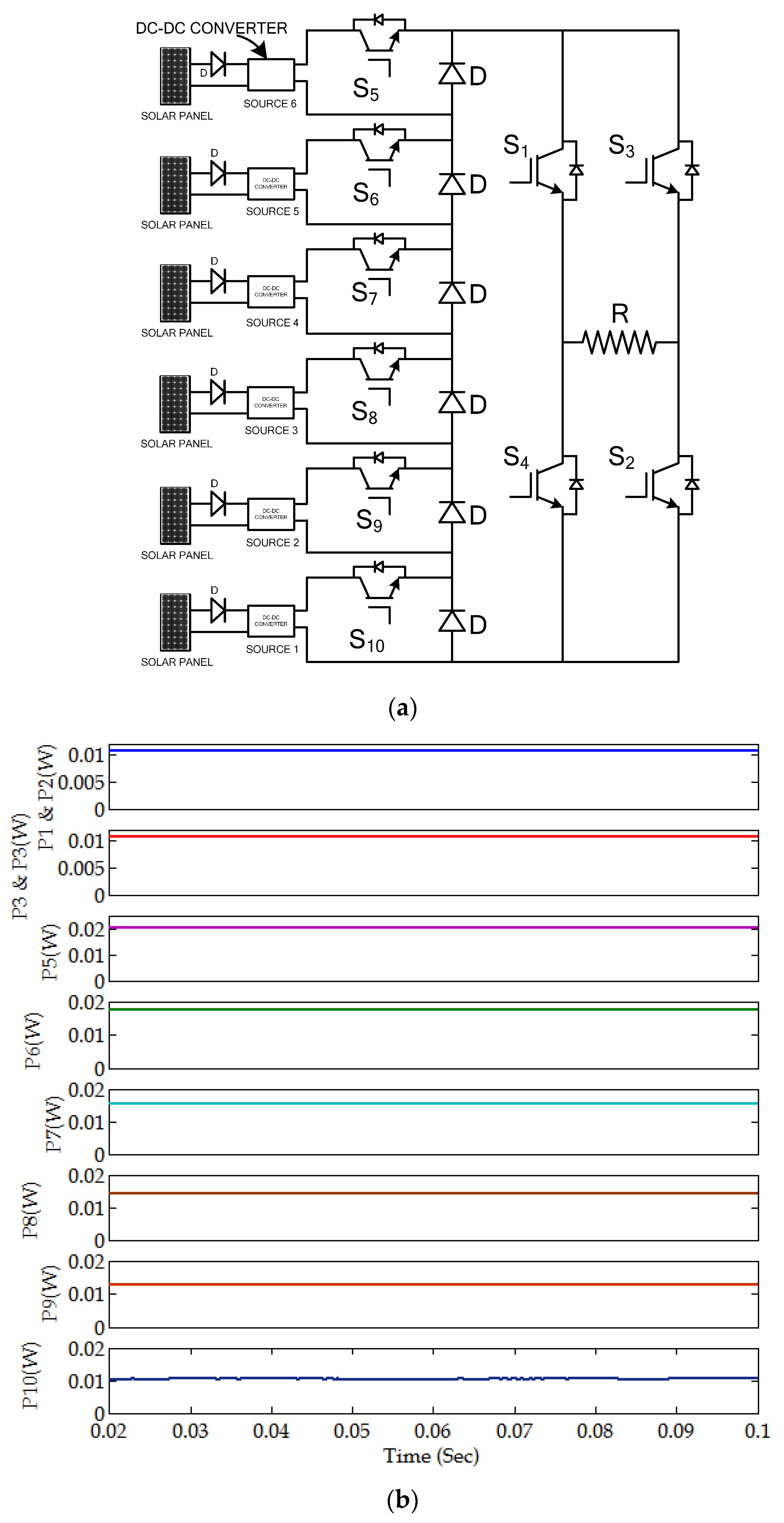
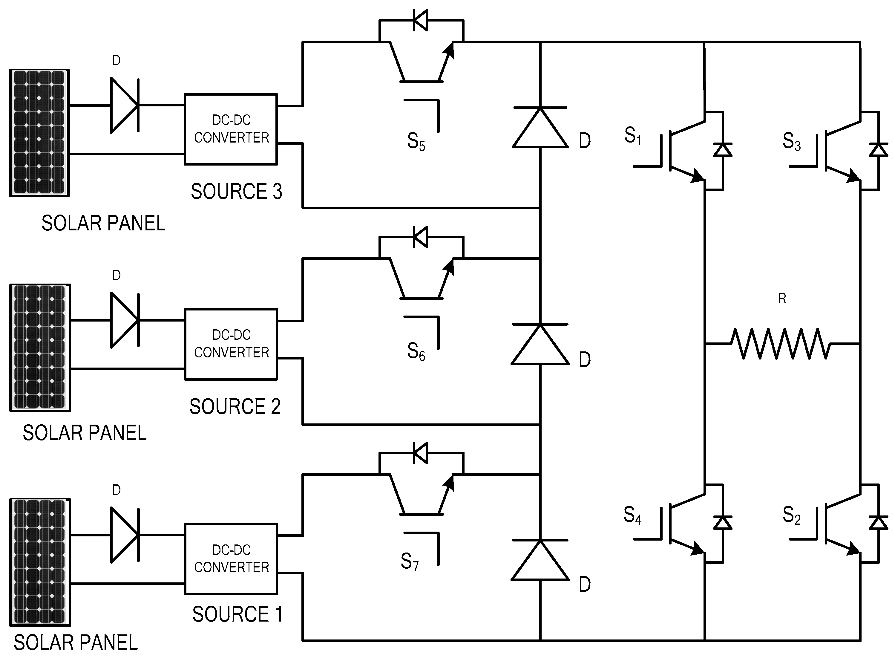
3. Proposed System Circuit and Its Configuration
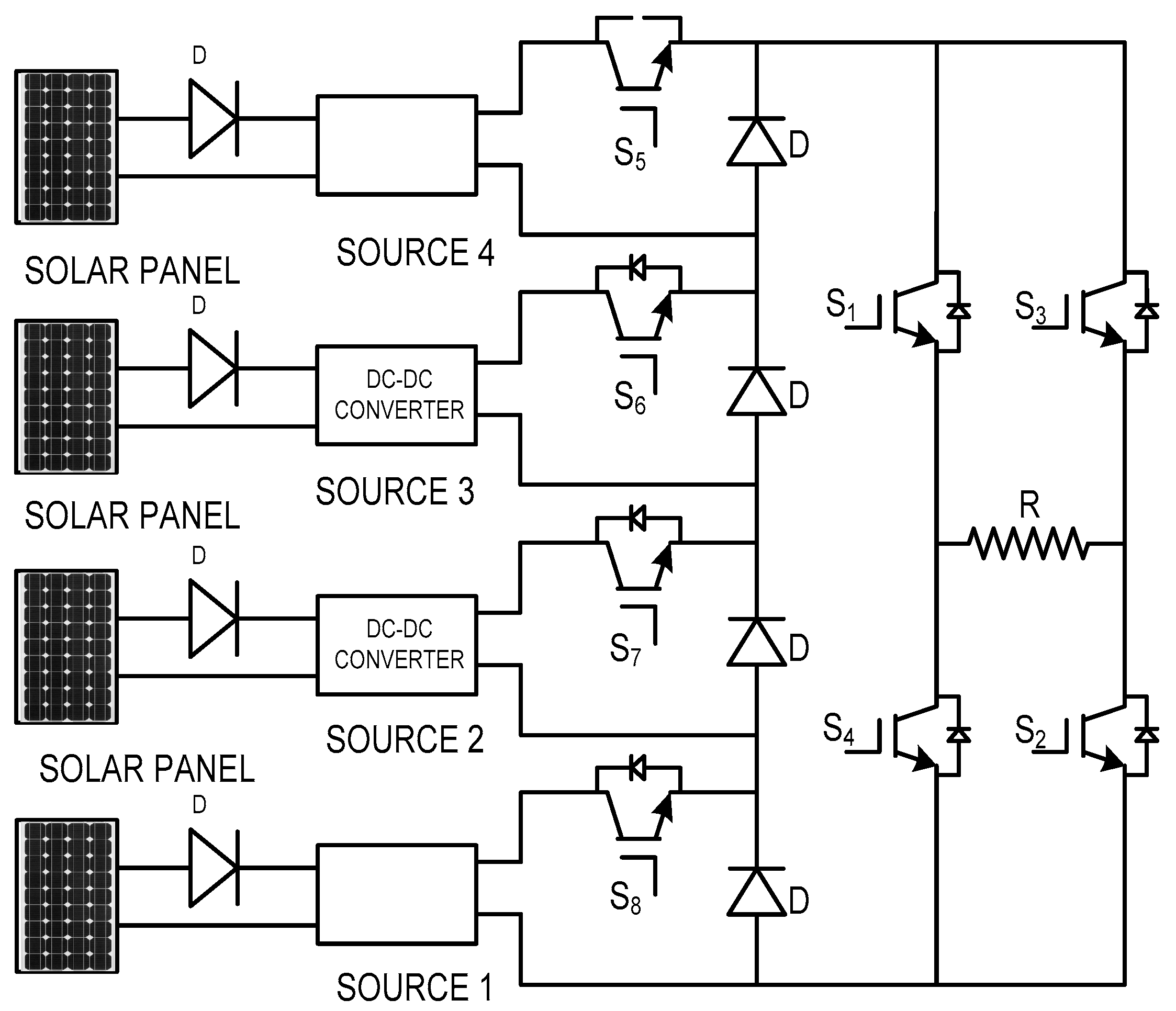
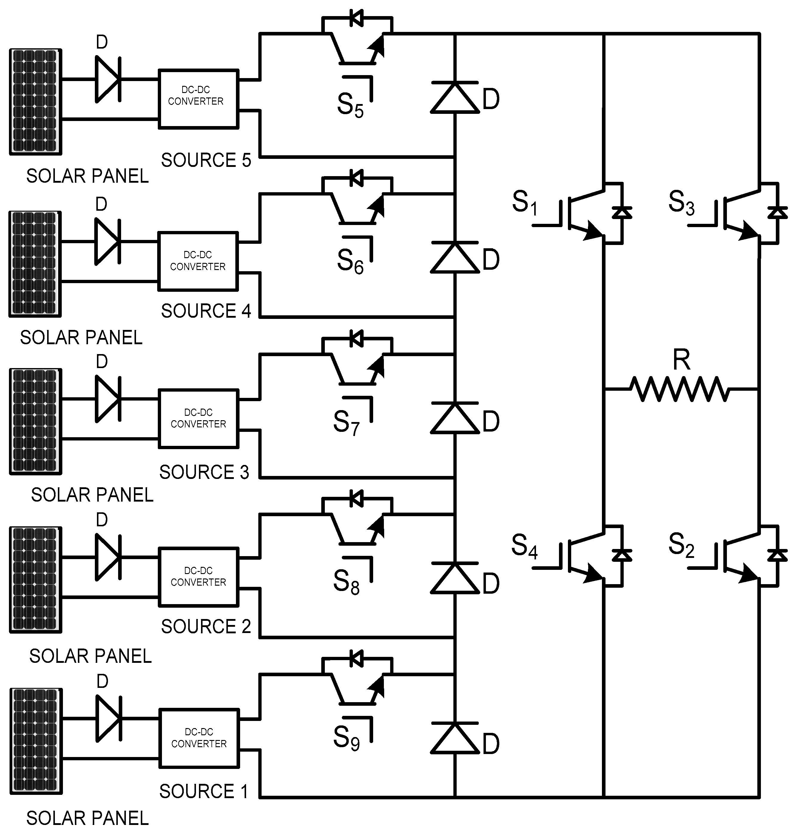
3.1. 127-Level Multilevel Inverter Circuit Diagram
3.2. 127-Level Multilevel Inverter Operation and Principle
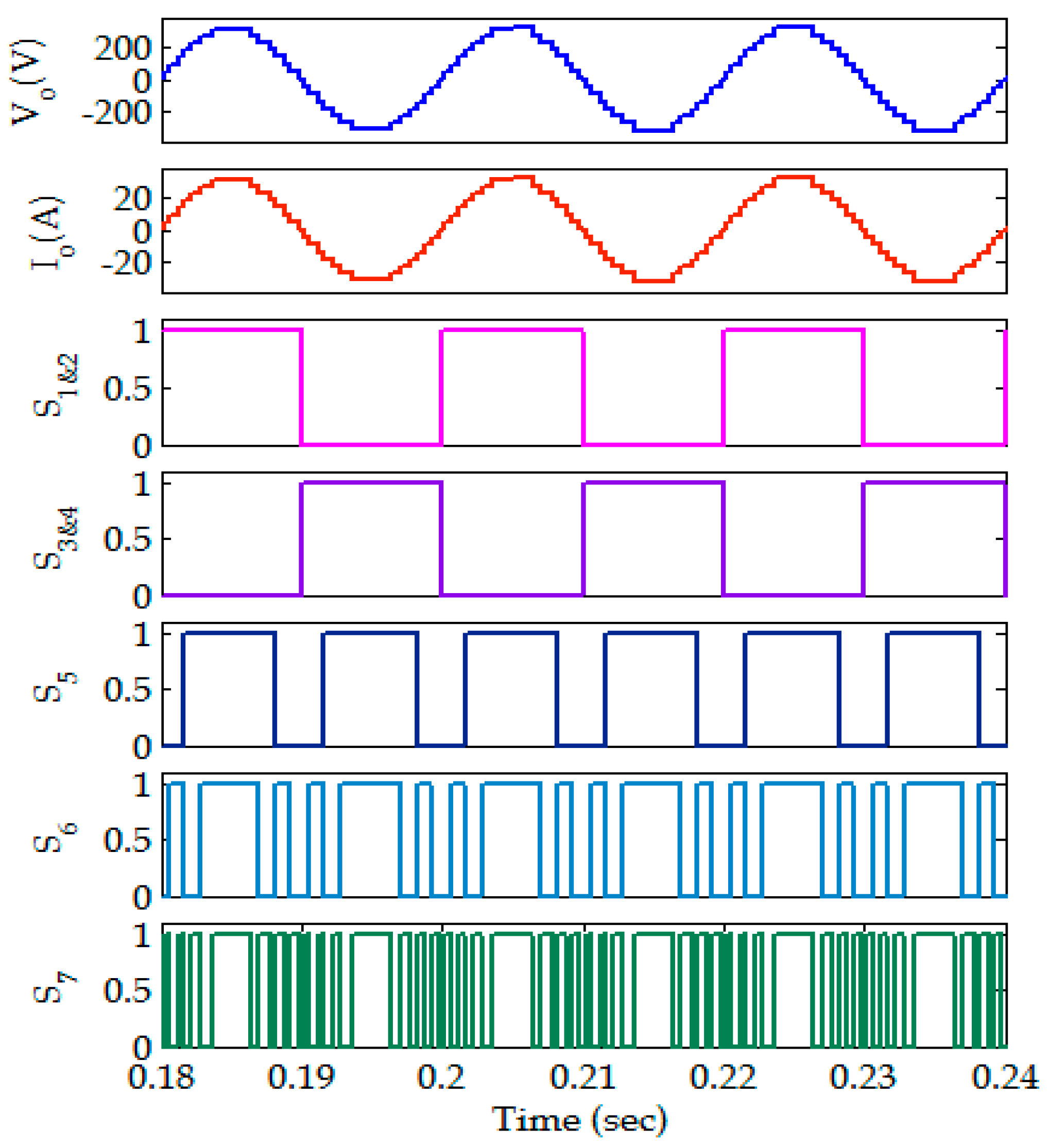
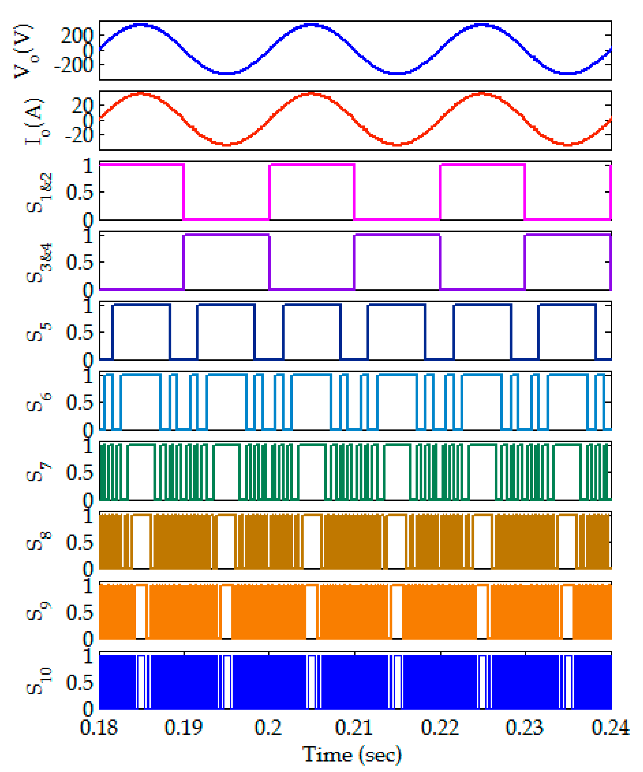
3.3. Switching Sequence of MLI for Positive Half Cycle
3.4. Voltage Stress Calculation for 127-Level Reduced Switch MLI
3.5. Power Losses for 127-Level Reduced Switch MLI
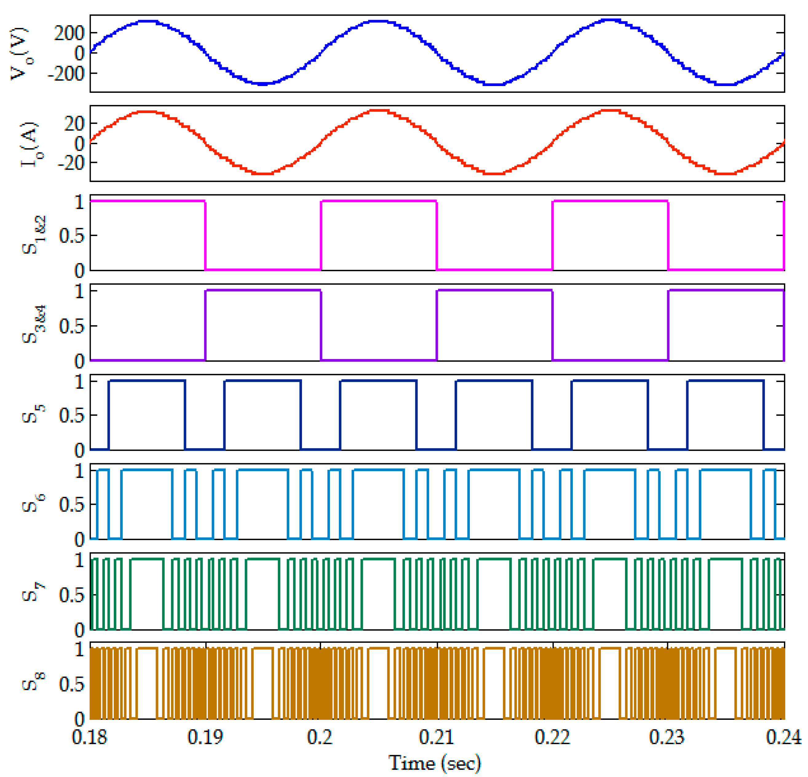
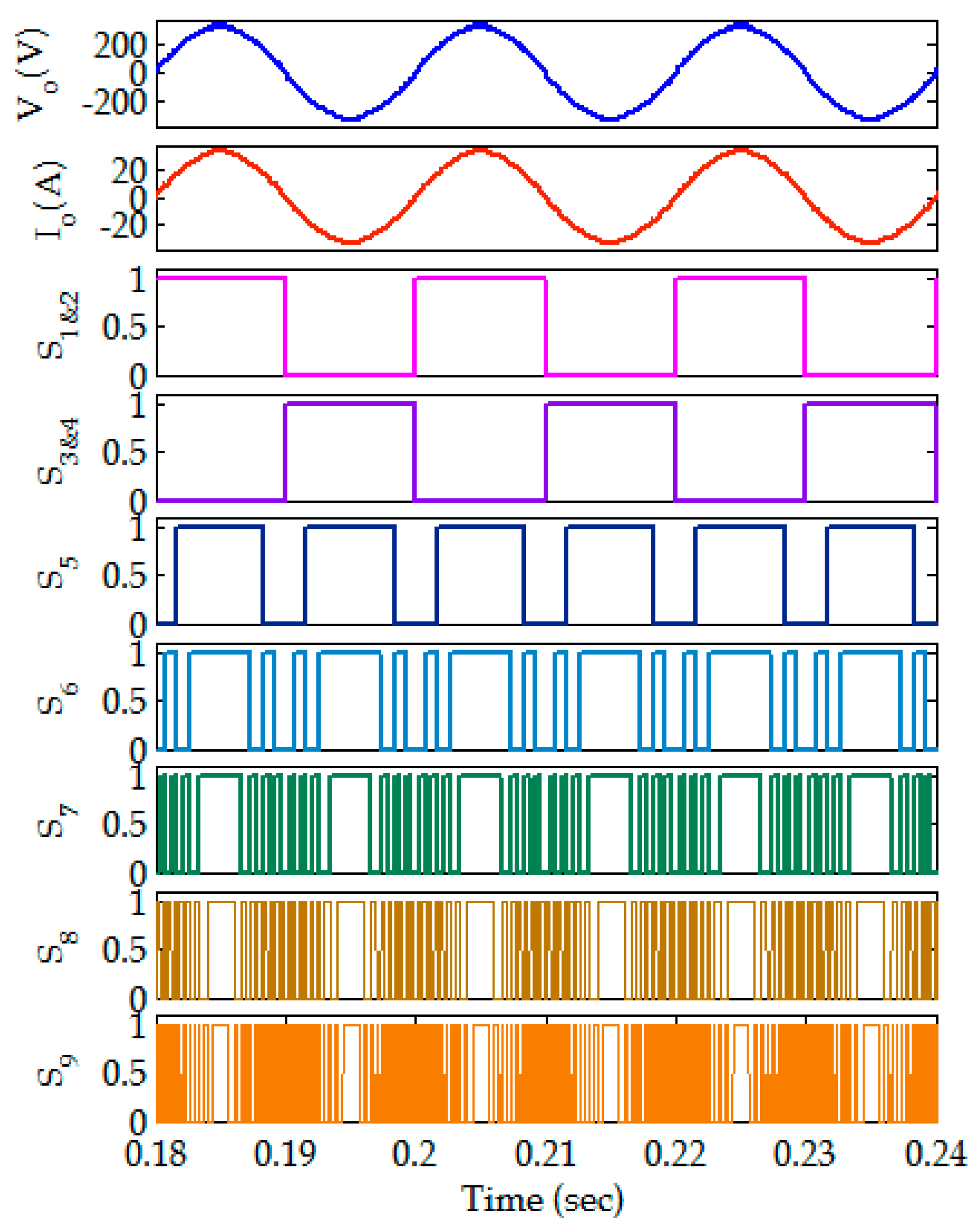
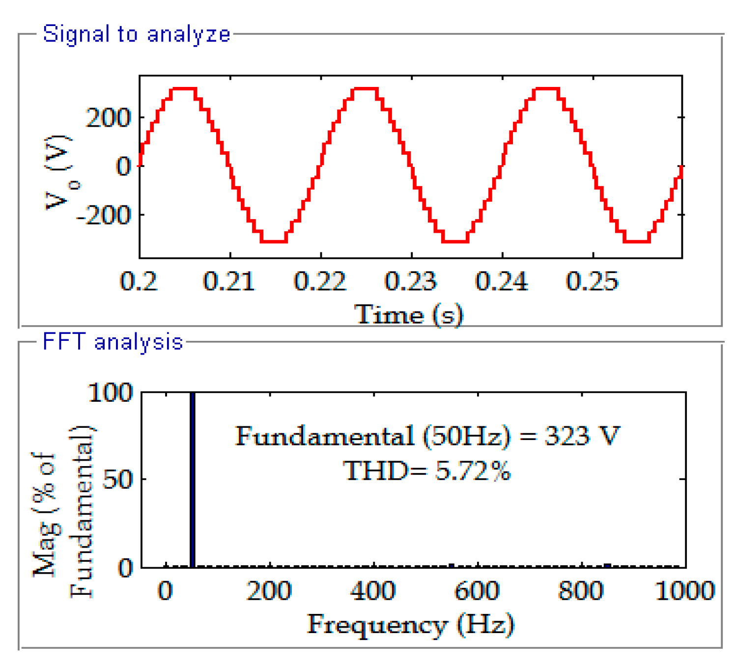
4. Results and Discussion
5. Conclusions
Author Contributions
Funding
Institutional Review Board Statement
Informed Consent Statement
Conflicts of Interest
References
- Babaei, E.; Jalilzadeh, T.; Sabahi, M.; Maalandish, M.; Alishah, R.S. High step-up DC–DC converter with reduced voltage stress on devices. IEEE Trans. Instrum. Electr. Energy Syst. 2018, 46, 2053–2078. [Google Scholar] [CrossRef]
- Prem, P.; Sathik, J.; Sivaraman, P.; Mathewsaran, A.; Aleem, S.H.E.A. A new asymmetric dual source multilevel inverter topology with reduced power switches. J. Chin. Instrum. Eng. 2019, 42, 460–472. [Google Scholar]
- Kouro, S.; Malinowski, M.; Gopakumar, K.; Pou, J.; Franquelo, L.G. Recent advances and industrial applications of multilevel converters. IEEE Trans. Ind. Electron. Syst. 2010, 57, 2553–2580. [Google Scholar] [CrossRef]
- Ali, J.S.M.; Alishah, R.S.; Sandeep, N.; Hosseini, S.H.; Babaei, E.; Vijayakumar, K.; Yaragatti, U.R. A new generalized multilevel converter topology based on cascaded connection of basic units. IEEE Trans. J. Emerg. Sel. Top. Power Electron. 2018, 7, 2498–2512. [Google Scholar]
- Meza, C.; Negroni, J.J.; Biel, D.; Guinjoan, F. Energy-balance modeling and discrete control for single-phase grid-connected PV central inverters. IEEE Trans. Ind. Electron. 2008, 55, 2734–2743. [Google Scholar] [CrossRef]
- Oikonomou, N.; Gutscher, C.; Karamanakos, P.; Kieferndorf, F.; Geyer, T. Model predictive pulse pattern control for the five-level active neutral point-clamped inverter. IEEE Trans. Ind. Appl. 2013, 46, 2583–2592. [Google Scholar] [CrossRef]
- Huang, J.; Corzine, K. Extended operation of flying capacitor multilevel inverters. IEEE Trans. Power Electron. 2006, 21, 140–147. [Google Scholar] [CrossRef]
- Amini, J. An effortless space-vector-based modulation for N-level flying capacitor multilevel inverter with capacitor voltage balancing capability. IEEE Trans. Power Electron. 2014, 57, 2633–2642. [Google Scholar]
- Villalva, M.G.; Gazoli, J.R.; Filho, E.R. Modeling and circuit-based simulation of photovoltaic arrays. Proc. Braz. Power Electron. Conf. 2009, 14, 35–45. [Google Scholar]
- Hasan, M.; Mekhilef, S.; Ahmed, M. Three-phase hybrid multilevel inverter with less power electronic components using space vector modulation. Power Electron. IET 2014, 16, 1504–1512. [Google Scholar] [CrossRef] [Green Version]
- Mekhilef, S.; Abdul Kadir, M.N.; Salam, Z. Digital control of three phase three-stage hybrid multilevel inverter. IEEE Trans. Ind. Inf. 2013, 9, 719–727. [Google Scholar] [CrossRef]
- Daher, S.; Schmid, J.; Antunes, F.L. Multi level inverter topologies for stand-alone PV systems. IEEE Trans. Ind. Electron. 2008, 55, 2703–2712. [Google Scholar] [CrossRef]
- Buticchi, G.; Barater, D.; Lorenzani, E.; Concari, C.; Franceschini, G. A nine-level grid-connected converter topology for single-phase transformerless PV systems. IEEE Trans. Ind. Electron. 2014, 61, 3951–3960. [Google Scholar] [CrossRef]
- Wu, J.C.; Chou, C.W. A solar power generation system with a seven-level inverter. IEEE Trans. Power Electron. 2014, 31, 2099–2110. [Google Scholar] [CrossRef]
- Gupta, K.K.; Jain, S. Comprehensive review of a recently proposed multilevel inverter. Power Electron. IET 2014, 7, 467–479. [Google Scholar] [CrossRef]
- Gupta, K.K.; Ranjan, A.; Bhatnagar, P.; Sahu, L.K.; Jain, S. Multilevel inverter topologies with reduced device count: A review. IEEE Trans. Power Electron. 2016, 31, 135–151. [Google Scholar] [CrossRef]
- Odeh, C.I. Enhanced three-phase multilevel inverter configuration. Power Electron. IET 2013, 6, 1122–1131. [Google Scholar] [CrossRef]
- Farhadi Kangarlu, M.; Babaei, E. Cross-switched multilevel inverter an innovative topology. IET Power Electron. 2013, 6, 1041–1050. [Google Scholar] [CrossRef]
- Odeh, C.I. Balancing switching losses in three-phase, five-level pulse width modulation switched voltage source inverter using hybrid modulation techniques. Electro. Power Compon. Syst. 2014, 8, 1194–1200. [Google Scholar] [CrossRef]
- Ruiz-Caballero, A.; Ramos-Astudillo, R.M.; Mussa, S.A.; Heldwein, M.L. Symmetrical hybrid multilevel DC–AC converters with reduced number of insulated DC supplies. IEEE Trans. Ind. Electron. 2010, 57, 2307–2314. [Google Scholar] [CrossRef]
- Tsai, C.T.; Chen, W.M. Buck converter with soft-switching cells for PV panel applications. Energies 2016, 9, 148. [Google Scholar] [CrossRef] [Green Version]
- Ando, Y.; Oku, T.; Yasuda, M.; Ushijima, K.; Murozono, M. A Transportable Photovoltaic Power Generation System Utilizing a SiC Inverter and Spherical Si Solar Cells. Technologies 2017, 5, 18. [Google Scholar] [CrossRef] [Green Version]
- Amamra, S.A.; Meghriche, K.; Cherifi, A.; Francois, B. Multilevel Inverter Topology for Renewable Energy Grid Integration. IEEE Trans. Ind. Electron. 2017, 64, 8855–8866. [Google Scholar] [CrossRef]
- Gopal, Y.; Birla, D.; Lalwani, M. Selected Harmonic Elimination for Cascaded Multilevel Inverter Based on Photovoltaic with Fuzzy Logic Control Maximum Power Point Tracking Technique. Technologies 2018, 6, 62. [Google Scholar] [CrossRef] [Green Version]
- Hota, A.; Jain, S.; Agarwal, V. An Improved Three-Phase Five-Level Inverter Topology with Reduced Number of Switching Power Devices. IEEE Trans. Ind. Electron. 2018, 65, 3296–3305. [Google Scholar] [CrossRef]
- Bassi, H.M.; Salam, Z. A new hybrid multilevel inverter topology with reduced switch count and dc voltage sources. Energies 2019, 12, 977. [Google Scholar] [CrossRef] [Green Version]
- Siddique, M.D.; Mekhilef, S.; Shah, N.M.; Sarwar, A.; Iqbal, A.; Memon, M.A. A New Multilevel Inverter Topology with Reduce Switch Count. IEEE Access 2019, 7, 58584–58594. [Google Scholar] [CrossRef]
- Sandeep, N.; Ali, J.S.M.; Yaragatti, U.R.; Vijayakumar, K. A Self-Balancing Five-Level Boosting Inverter with Reduced Components. IEEE Trans. Power Electron. 2019, 34, 6020–6024. [Google Scholar] [CrossRef]
- Periyanayagam, M.; Kumar, V.S.; Chokkalingam, B.; Padmanaban, S.; Mihet-Popa, L.; Adedayo, Y. A modified high voltage gain quasi-impedance source coupled inductor multilevel inverter for photovoltaic application. Energies 2020, 13, 874. [Google Scholar] [CrossRef] [Green Version]
- Kakar, S.; Ayob, S.B.M.; Iqbal, A.; Nordin, N.M.; Arif, M.S.B.; Gore, S. New Asymmetrical Modular Multilevel Inverter Topology with Reduced Number of Switches. IEEE Access 2021, 9, 27627–27637. [Google Scholar] [CrossRef]
- Sathik, J.; Aleem, S.H.E.; Alishah, R.S.; Almakhles, D.; Bertilsson, K.; Bhaskar, M.S.; Savier, G.F.; Dhandapani, K. A Multilevel Inverter Topology Using Diode Half-Bridge Circuit with Reduced Power Component. Energies 2021, 14, 7249. [Google Scholar] [CrossRef]
- Rawa, M.; Prem, P.; Mohamed Ali, J.S.; Siddique, M.D.; Mekhilef, S.; Wahyudie, A.; Seyedmahmoudian, M.; Stojcevski, A. A new multilevel inverter topology with reduced dc sources. Energies 2021, 14, 4709. [Google Scholar] [CrossRef]
- Farahmand, M.Z.; Javadi, S.; Sadati, S.M.B.; Laaksonen, H.; Shafie-khah, M. Optimal Operation of Solar Powered Electric Vehicle Parking Lots Considering Different Photovoltaic Technologies. Clean Technol. 2021, 3, 503–518. [Google Scholar] [CrossRef]
- Arif, M.S.B.; Mustafa, U.; Ayob, S.B.M.; Rodriguez, J.; Nadeem, A.; Abdelrahem, M. Asymmetrical 17-Level Inverter Topology with Reduced Total Standing Voltage and Device Count. IEEE Access 2021, 9, 69710–69723. [Google Scholar] [CrossRef]
- Mukundan, N.C.; Kallaveetil, V.; Suresh, S.; Pychadathil, J. An Improved H-Bridge Multilevel Inverter-Based. IEEE Trans. Ind. Electron. 2021, 57, 6339–6349. [Google Scholar]


| STEP 1 | S5 | S6 | S7 | S8 | S9 | S10 | Output (V0) |
|---|---|---|---|---|---|---|---|
| 0 | 0 | 0 | 0 | 0 | 0 | 0 | |
| 1 | 0 | 0 | 0 | 0 | 0 | 1 | |
| 2 | 0 | 0 | 0 | 0 | 1 | 0 | |
| 3 | 0 | 0 | 0 | 0 | 1 | 1 | |
| 4 | 0 | 0 | 0 | 1 | 0 | 0 | |
| 5 | 0 | 0 | 0 | 1 | 0 | 1 | |
| 6 | 0 | 0 | 0 | 1 | 1 | 0 | |
| 7 | 0 | 0 | 0 | 1 | 1 | 1 | |
| 8 | 0 | 0 | 1 | 0 | 0 | 0 | |
| 9 | 0 | 0 | 1 | 0 | 0 | 1 | |
| 10 | 0 | 0 | 1 | 0 | 1 | 0 | |
| 11 | 0 | 0 | 1 | 0 | 1 | 1 | |
| 12 | 0 | 0 | 1 | 1 | 0 | 0 | |
| 13 | 0 | 0 | 1 | 1 | 0 | 1 | |
| 14 | 0 | 0 | 1 | 1 | 1 | 0 | |
| 15 | 0 | 0 | 1 | 1 | 1 | 1 | |
| 16 | 0 | 1 | 0 | 0 | 0 | 0 | |
| 17 | 0 | 1 | 0 | 0 | 0 | 1 | |
| 18 | 0 | 1 | 0 | 0 | 1 | 0 | |
| 19 | 0 | 1 | 0 | 0 | 1 | 1 | |
| 20 | 0 | 1 | 0 | 1 | 0 | 0 | |
| 21 | 0 | 1 | 0 | 1 | 0 | 1 | |
| 22 | 0 | 1 | 0 | 1 | 1 | 0 | |
| 23 | 0 | 1 | 0 | 1 | 1 | 1 | |
| 24 | 0 | 1 | 1 | 0 | 0 | 0 | |
| 25 | 0 | 1 | 1 | 0 | 0 | 1 | |
| 26 | 0 | 1 | 1 | 0 | 1 | 0 | |
| 27 | 0 | 1 | 1 | 0 | 1 | 1 | |
| 28 | 0 | 1 | 1 | 1 | 0 | 0 | |
| 29 | 0 | 1 | 1 | 1 | 0 | 1 | |
| 30 | 0 | 1 | 1 | 1 | 1 | 0 | |
| 31 | 0 | 1 | 1 | 1 | 1 | 1 | |
| 32 | 1 | 0 | 0 | 0 | 0 | 0 | |
| 33 | 1 | 0 | 0 | 0 | 0 | 1 | |
| 34 | 1 | 0 | 0 | 0 | 1 | 0 | |
| 35 | 1 | 0 | 0 | 0 | 1 | 1 | |
| 36 | 1 | 0 | 0 | 1 | 0 | 0 | |
| 37 | 1 | 0 | 0 | 1 | 0 | 1 | |
| 38 | 1 | 0 | 0 | 1 | 1 | 0 | |
| 39 | 1 | 0 | 0 | 1 | 1 | 1 | |
| 40 | 1 | 0 | 1 | 0 | 0 | 0 | |
| 41 | 1 | 0 | 1 | 0 | 0 | 1 | |
| 42 | 1 | 0 | 1 | 0 | 1 | 0 | |
| 43 | 1 | 0 | 1 | 0 | 1 | 1 | |
| 44 | 1 | 0 | 1 | 1 | 0 | 0 | |
| 45 | 1 | 0 | 1 | 1 | 0 | 1 | |
| 46 | 1 | 0 | 1 | 1 | 1 | 0 | |
| 47 | 1 | 0 | 1 | 1 | 1 | 1 | |
| 48 | 1 | 1 | 0 | 0 | 0 | 0 | |
| 49 | 1 | 1 | 0 | 0 | 0 | 1 | |
| 50 | 1 | 1 | 0 | 0 | 1 | 0 | |
| 51 | 1 | 1 | 0 | 0 | 1 | 1 | |
| 52 | 1 | 1 | 0 | 1 | 0 | 0 | |
| 53 | 1 | 1 | 0 | 1 | 0 | 1 | |
| 54 | 1 | 1 | 0 | 1 | 1 | 0 | |
| 55 | 1 | 1 | 0 | 1 | 1 | 1 | |
| 56 | 1 | 1 | 1 | 0 | 0 | 0 | |
| 57 | 1 | 1 | 1 | 0 | 0 | 1 | |
| 58 | 1 | 1 | 1 | 0 | 1 | 0 | |
| 59 | 1 | 1 | 1 | 0 | 1 | 1 | |
| 60 | 1 | 1 | 1 | 1 | 0 | 0 | |
| 61 | 1 | 1 | 1 | 1 | 0 | 1 | |
| 62 | 1 | 1 | 1 | 1 | 1 | 0 | |
| 63 | 1 | 1 | 1 | 1 | 1 | 1 |
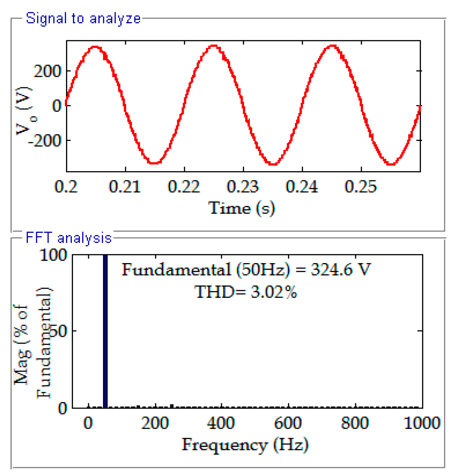
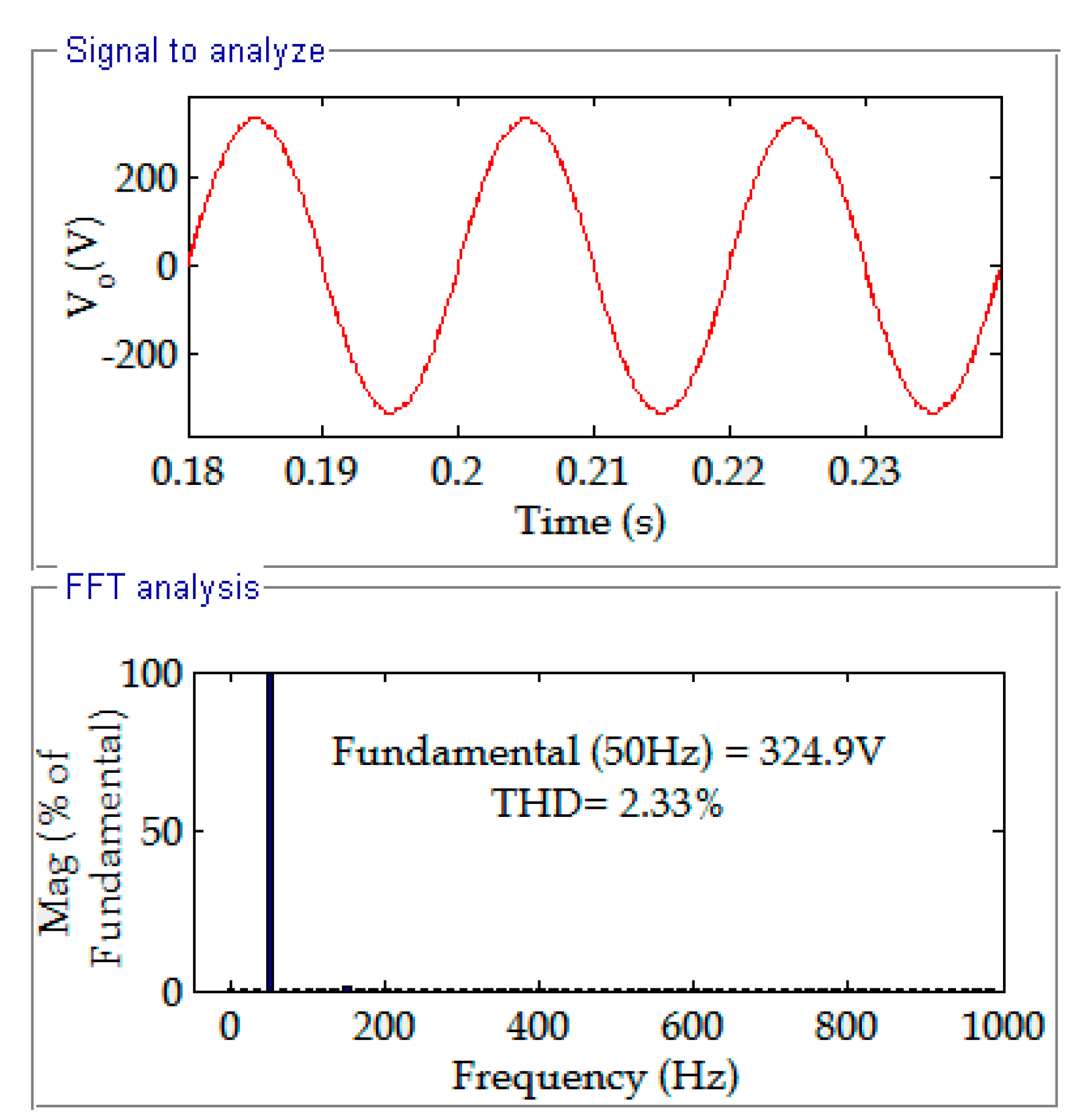
| No. of Levels | 15 | 31 | 63 | 127 | 15 |
| No. of IGBT Switches | 07 | 08 | 09 | 10 | 07 |
| No. of Diodes | 03 | 04 | 05 | 06 | 03 |
| No. of Voltage Sources | 03 | 04 | 05 | 06 | 03 |
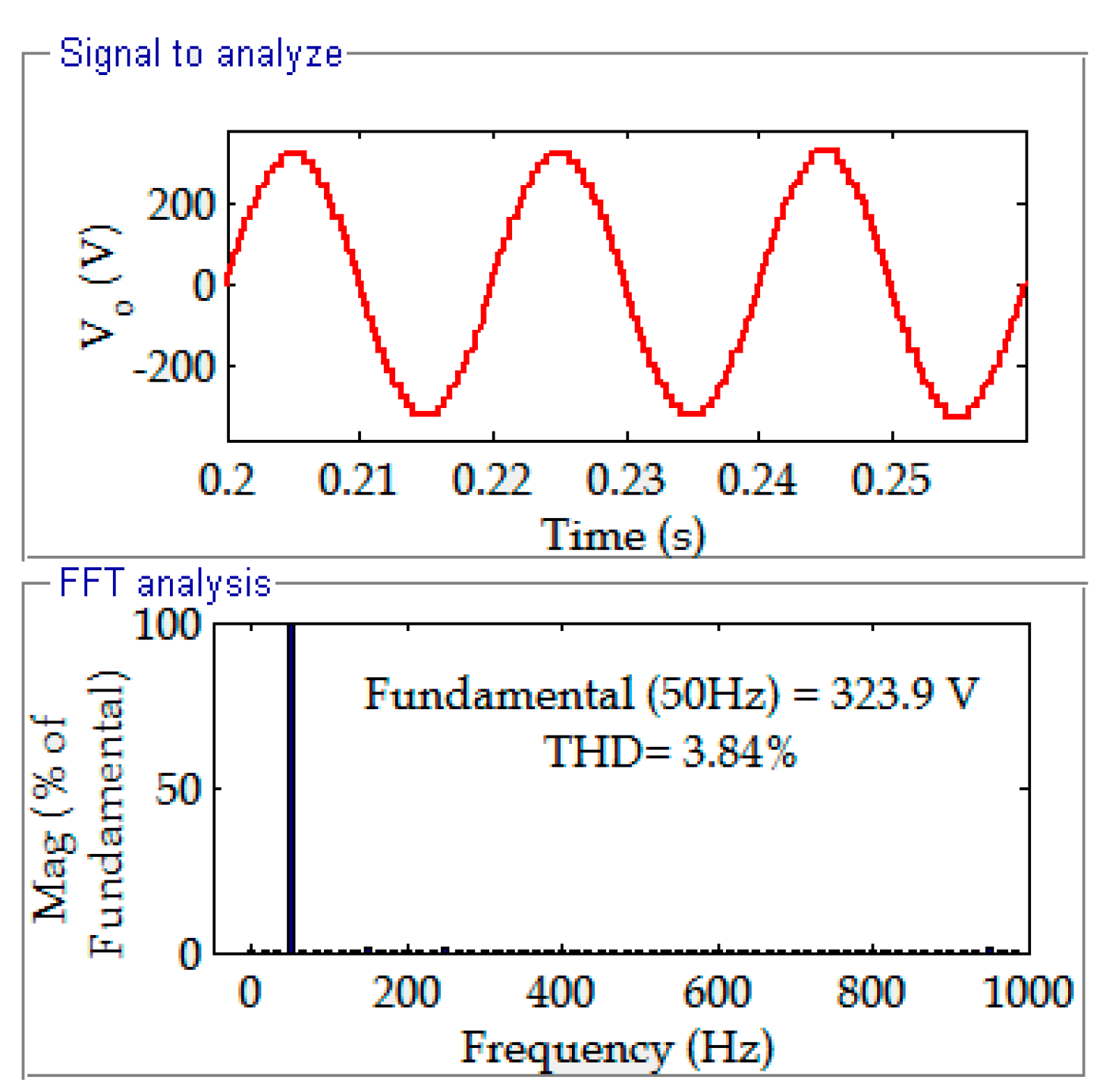
| Fundamental Voltage | 323 V | 323.9 V | 324.6 V | 324.9 V | 323 V |
| % of THD | 5.72 | 3.84 | 3.02 | 2.33 | 5.72 |
| Topologies | NPC MLI | CHB MLI | FC MLI | SC MLI | Proposed Topology |
|---|---|---|---|---|---|
| Main switches | 28 | 28 | 28 | 13 | 10 |
| Main diodes | 28 | 28 | 28 | 13 | 10 |
| Clamping diodes | 182 | 0 | 0 | 02 | 07 |
| DC-sources | 14 | 7 | 14 | 01 | 06 |
| Flying capacitors | 0 | 0 | 91 | 0 | 0 |
| Gate driver circuits | 28 | 28 | 28 | 13 | 10 |
| Variety of DC sources | 01 | 07 | 01 | 01 | 06 (Vdc1, Vdc2, Vdc3, Vdc4, Vdc5, Vdc6) |
| Maximum output voltage | Vdc | 7 × Vdc | Vdc | 6 × Vdc | 2 × Vdc6 − Vdc1 |
| Number of levels | 15 Levels | 15 Levels | 15 Levels | 13 Levels | 127 Levels |
Publisher’s Note: MDPI stays neutral with regard to jurisdictional claims in published maps and institutional affiliations. |
© 2022 by the authors. Licensee MDPI, Basel, Switzerland. This article is an open access article distributed under the terms and conditions of the Creative Commons Attribution (CC BY) license (https://creativecommons.org/licenses/by/4.0/).
Share and Cite
Andela, M.; Shaik, A.; Beemagoni, S.; Kurimilla, V.; Veramalla, R.; Kodakkal, A.; Salkuti, S.R. Solar Photovoltaic System-Based Reduced Switch Multilevel Inverter for Improved Power Quality. Clean Technol. 2022, 4, 1-13. https://doi.org/10.3390/cleantechnol4010001
Andela M, Shaik A, Beemagoni S, Kurimilla V, Veramalla R, Kodakkal A, Salkuti SR. Solar Photovoltaic System-Based Reduced Switch Multilevel Inverter for Improved Power Quality. Clean Technologies. 2022; 4(1):1-13. https://doi.org/10.3390/cleantechnol4010001
Chicago/Turabian StyleAndela, Madhu, Ahmmadhussain Shaik, Saicharan Beemagoni, Vishal Kurimilla, Rajagopal Veramalla, Amritha Kodakkal, and Surender Reddy Salkuti. 2022. "Solar Photovoltaic System-Based Reduced Switch Multilevel Inverter for Improved Power Quality" Clean Technologies 4, no. 1: 1-13. https://doi.org/10.3390/cleantechnol4010001
APA StyleAndela, M., Shaik, A., Beemagoni, S., Kurimilla, V., Veramalla, R., Kodakkal, A., & Salkuti, S. R. (2022). Solar Photovoltaic System-Based Reduced Switch Multilevel Inverter for Improved Power Quality. Clean Technologies, 4(1), 1-13. https://doi.org/10.3390/cleantechnol4010001