1. Introduction
Based on the “Statistical review of world energy” provided by the BP Company (London, United Kingdom), the global R/P (reserve/production) ratios of fossil fuels reveal that oil and natural gas could be still exploited for 50 years. In contrast, for coal, the exploitation duration has been estimated at 132 years [
1]. This exploitation duration has been assessed relying on the proved reserves in 2019 and considering the current production. While oil and natural gas consumption has grown over the last years, coal consumption has declined due to the growing use of natural gas and the development of renewable energy sources (RES), particularly in the power sector [
2]. However, despite the decrease in consumption, coal remains the most used fuel for power generation (around 36.4%). In comparison, natural gas represents 23.3%, followed by hydroelectric (around 15.6%), and then by renewables (about 10.4%), surpassing nuclear (approximately 10.35%) for the first time [
1].
Over the last years, the huge penetration of RES (wind, photovoltaic) in the power generation combined with slower growth in energy demand has led to a consequential slowdown in the rise of greenhouse gas (GHG) emissions. Indeed, the global capacity of photovoltaic energy reached 586 GW in 2019 (an increase of 20% compared to 2018); whereas the global capacity of wind energy represents 622 GW (a rise of 10.4% compared to 2018) [
1].
Despite the growing development and the interest in RES, some economic sectors such as energy production, transportation, and industry still suffer from releasing a large number of CO
2 emissions caused by the use of fossil fuels [
3,
4]. These emissions disturb the global climate by the rise in temperature and water level in some areas and the increase of meteorological phenomena. To face these challenging issues, the employment of hydrogen as a sustainable fuel has attracted a lot of attention from researchers, industrials, and governments over the last years [
5,
6]. Indeed, hydrogen as an energy carrier (able to store and deliver useful energy) presents several benefits such as its combustion with oxygen, generating only water and a high energy density per mass (120 MJ·kg
−1). This energy density is nearly three times higher than gasoline (44 MJ·kg
−1) and kerosene (42.8 MJ·kg
−1), supplying cars and aircraft, respectively. However, hydrogen introduces several disadvantages; it does not exist under its natural state on Earth. Besides, it features low energy density per volume since it is the lightest existing gas based on the periodic table [
7,
8].
The storage of hydrogen is a key issue for devising hydrogen technologies in applications (transportation, stationary and portable power). Therefore, the development of advanced hydrogen storage solutions is required to offer a higher energy density [
9]. These solutions include physical and material-based storage. Firstly, hydrogen can be stored either as a gas or liquid. Hydrogen storage as a gas generally requires suitable high-pressure tanks (between 350 and 700 bars) [
10]. In comparison, hydrogen storage as a liquid requires cryogenic temperatures since the boiling point of hydrogen is −252.8 °C (at one-atmosphere pressure, corresponding to 20.3 K) [
11]. Secondly, hydrogen can be stored on the surfaces of solids or, by adsorption, within solids as in metal hydrides materials [
9]. Liquid hydrogen can offer an energy density per volume of around 8 MJ·L
−1 (higher than hydrogen storage based on high-pressure tanks) while for gasoline and kerosene, the energy density per volume is equal to 32 MJ·L
−1 and 35 MJ·L
−1, respectively. In light-duty fuel cell electric vehicles (FCEV), a driving range of more than 300 miles (around 482.8 km) is expected. As a result, onboard hydrogen storage capability ranging from 5 to 13 kg of hydrogen is needed to meet the expected driving range [
9].
Hydrogen is combined with compounds such as oxygen (water), carbon (natural gas, coal), and oxygen-carbon (plant biomass). Hence, it can be obtained from various thermochemical processes using natural gas, coal, or biomass. These thermochemical processes include biomass gasification, biomass-derived liquid reforming, coal gasification, natural gas reforming, and solar thermochemical hydrogen [
12,
13]. Other types of processes can be found. They include electrolytic, direct solar water splitting (photoelectrochemical), and biological (microbial biomass conversion) processes [
14]. Currently, thermochemical processes mainly based on natural gas reforming and coal gasification are widespread due to their maturity and low-cost production. However, due to the process reactions, GHGs are emitted, such as carbon dioxide and monoxide. For this reason, advanced research and development need to overcome these issues in terms of carbon capture, valorization, and storage technologies (guaranteeing that minimal GHGs are released in the atmosphere) [
15,
16].
On the other hand, hydrogen production via water electrolysis has taken advantage of increasing interest from nations all over the world to start the decarbonization of some economic sectors, especially the industry and transportation sectors [
7,
14]. Indeed, the water electrolysis process principle relies on the use of electricity to split the pure water into hydrogen and oxygen. Water is an abundant resource on Earth and different types of power sources can be used for the process [
17,
18]. However, to assess the profits and the economic feasibility of employing water electrolysis, the cost, the efficiency, and the carbon emissions of the used power source for electricity generation must be considered [
19]. In fact, in some countries, where the electricity is obtained by coal-fired and gas-fired power plants, the power distribution grid is not the most suitable power source to supply water, resulting in a further contribution to global GHG emissions, and global warming accordingly [
19]. For this reason, to disseminate the water electrolysis process in generating a green and efficient fuel, power sources based on wind, sun, water, and nuclear have to be considered [
7,
20]. On the one hand, the carbon footprint can be drastically minimized by using these power sources to generate low-carbon power. On the other hand, water electrolysis faces some challenging issues that must be overcome, reducing the capital cost of the electrolyzer system, enhancing energy efficiency for transforming electricity into hydrogen, and integrating the compressor into the electrolyzer (to avoid the use of an external unit leading to an additional cost) [
19,
21].
It should be underlined that the efficient generation of hydrogen by water electrolysis depends on the whole conversion chain involving a multi-disciplinary approach. It encompasses the sources [
22], including their dynamic behavior [
23,
24,
25], the power electronics-based converter to interface the electrolyzer with the supply [
26,
27,
28,
29], and suitable modeling of the load, meaning the electrolyzer [
30,
31], additional issues concern the compliance with requirements related to the electromagnetic compatibility that need appropriate filter design [
32,
33]. These aspects have been discussed in detail by the authors beforehand. In particular, [
22] shows how the optimal use of the electrical energy source also depends on the electronic converter, whose improved efficiency diminishes the pay-back time and makes the conversion chain more sustainable. Papers [
23,
24,
25] show that, when using renewable sources, the dynamic behavior of the sources must be considered in the model of both the source and the converter to improve conversion in the presence of abrupt changes in wind speed or solar radiation. An example of this approach is shown in [
26,
27] for the converter and in [
30,
31] for the electrolyzer. Issues discussed in [
32,
33] concerning the electromagnetic interference (EMI), show that the conversion chain, due to the presence of switching converters, generates high-frequency noise which tends to propagate throughout the conductors and radiate into the surrounding environment; the presence of appropriate filters avoids these problems of electromagnetic compatibility.
The water electrolysis process is performed by an electrolyzer whose size can vary from small equipment (perfectly fit for small-scale distributed production systems) to large-scale facilities (central production facilities) [
19]. Since electrolyzers are electrochemical conversion systems operating with the same principle of fuel cells (FCs), they encompass an anode and a cathode; an electrolyte separates them. Different technologies of electrolyzers exist whose operation principles vary depending on the adopted electrolyte. The three types of electrolyzers are alkaline, proton exchange membrane (PEM), and solid oxide (SO) [
34]. Recently, anion exchange membrane (AEM) electrolyzers have been introduced as a promising and cost-effective technology for hydrogen production [
35]. However, like SO electrolyzers, AEM electrolyzers are currently undergoing research and development, and further improvements are expected to disseminate this technology to a large scale.
Alkaline and PEM electrolyzers are commercially available in the market. Firstly, alkaline electrolyzers work via the move of hydroxide ions (OH
−) from the cathode to the anode through the electrolyte. Oxygen is generated at the anode side and hydrogen is at the cathode side. These electrolyzers employ a liquid alkaline solution relying on potassium hydroxide (KOH) or sodium hydroxide (NaOH). The main advantages are the cost (due to cheaper catalysts), high lifetime, high gas purity, high efficiency, and high hydrogen production capacity. However, alkaline electrolyzers feature limited current density (0.2–0.4 A·cm
−2) and a slow response to dynamic operations [
36]. Furthermore, frequent maintenance (due to the liquid electrolyte) is requested to maintain safe operations.
On the other hand, PEM electrolyzers operate through a solid polymer electrolyte (SPE). The pure water is injected at the anode side and reacts to create oxygen and positively charged protons. These protons move through the SPE and the electrons flow through an external circuit. At the cathode side, protons and electrons are then combined forming hydrogen. On one side, the main advantages of this topology are the high current density (0.6–2 A·cm
−2), efficiency, and flexibility (partial load range included between 0 and 100%). Besides, the use of an SPE allows reducing maintenance costs. On the other hand, PEM electrolyzers are expensive because of noble materials (iridium, platinum), and the hydrogen capacity is lower than the alkaline electrolyzers [
14,
36].
Once hydrogen is generated from water electrolysis, it can be employed in many applications such as:
Transportation, material handling, stationary, portable, and emergency backup power applications through the use of an FC (using hydrogen as fuel and oxygen to produce electricity, water, and heat) [
37,
38,
39];
Energy storage [
7,
34,
38];
Recently, two review works dealing with hydrogen applications have been published in the literature [
7,
39]. In [
7], the authors have reviewed the four usual applications (storage of energy, power-to-gas, FC co-generation and tri-generation, and automotive), leaning on some projects, for disseminating hydrogen as an energy carrier. In comparison, in [
39], the authors outlined the current and future hydrogen applications such as aviation and maritime fuels, energy, FCs, fuel upgrading, metallurgy, and pharmaceuticals. However, the outline of each hydrogen application did not mention example projects.
Thus, building on these survey works, the purpose of this work is to provide an overview of the main considered hydrogen applications (including present and future) relying on example projects to build a prosperous future for the nation by addressing all the critical challenges met all energy sectors. For this reason, most of the cited contributions deal with realizations with a Technology Readiness Level (TRL) greater than four.
Our attention is focused on recent applications and technologies and on future perspectives based on funded research projects (including present and future). The novelty can be recognized in the proposed approach that considers (a) practical realizations, (b) investments (referred to EU), and (c) barriers.
This work relies on four sections. Following the introduction reviewing the current state-of-the-art about hydrogen considered as an energy carrier and related current issues, Section Two aims to give an outline of low-carbon power sources for water electrolysis relying on wind, sun, water, and nuclear. Section Three provides an overview of the main considered hydrogen applications (including present and future) leaning on example projects. Section Four shows the European approach for the hydrogen roadmap. Section Five deals with safety considerations and barriers. Finally, the conclusions outline the main key points regarding the future of hydrogen.
2. Outline of Low-Carbon Power Sources for Water Electrolysis
As mentioned in the introduction, the water electrolysis process is a viable alternative for hydrogen generation by using electricity to split pure water into hydrogen and oxygen. However, particular attention must be paid to the used power source in terms of cost, efficiency, and related CO
2 emissions. Indeed, the main challenges to overcome are the cost of the hydrogen and electrolyzer system, the energy efficiency to convert electricity to hydrogen, and finally the degradation process when coupling the electrolyzers with dynamic sources. For this reason, the current research is focused on the following items [
19,
44]:
To meet a clean hydrogen cost target of $2/kg H2 by 2025 (and $1/kg H2 by 2030 as future target) through a better understanding of electrolyzer systems’ performance, cost, and lifespan relying on forecast future dynamic operating conditions using low-carbon electricity. The objective is to make this process more competitive with a more mature hydrogen production pathway relying on natural gas reforming.
To decrease the global cost of the electrolyzer system (the target is around 300 $/kW)
To enhance energy efficiency to transform electricity into hydrogen throughout a broad range of operating conditions (the goal is to reach 77%) and to decrease energy specific consumption (around 43%).
To have an improved understanding of stack degradations mechanisms because of dynamic operating conditions. Thus, mitigation strategies are needed to optimize the performance of the electrolyzers and their durability [
45].
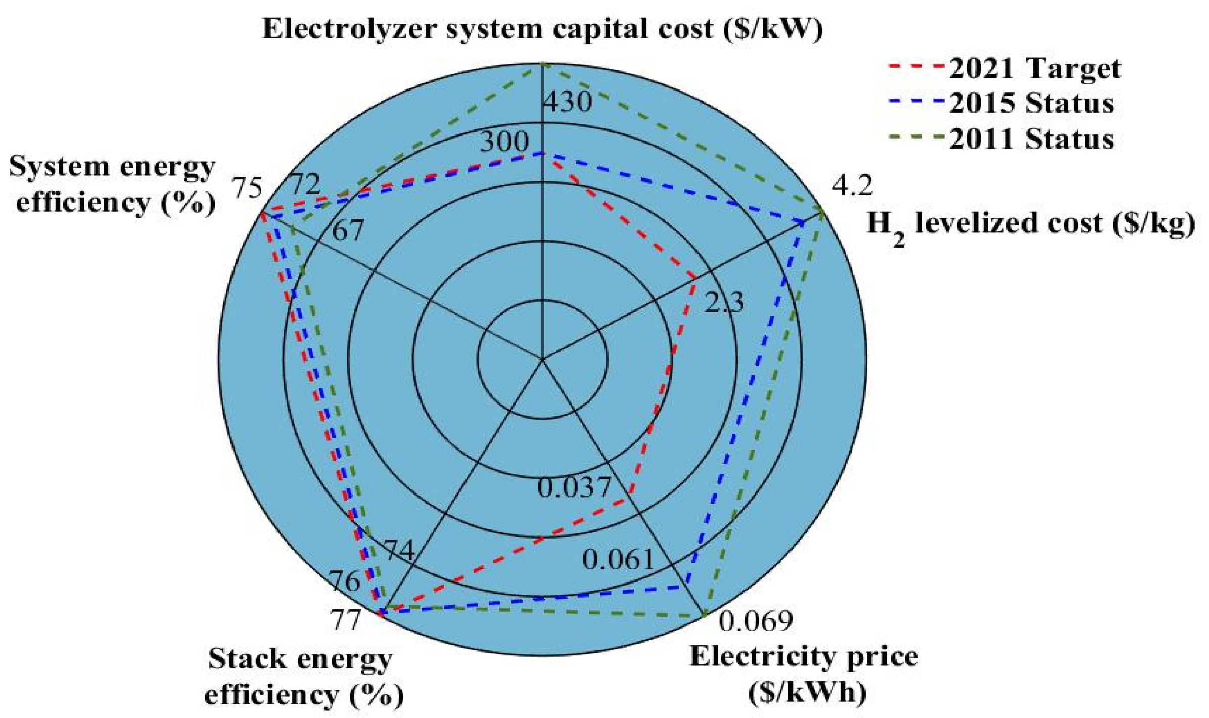
The most significant technical barriers that must face hydrogen production through water electrolysis are synthesized in the radar diagram given in
Figure 1, reporting the status (2011 and 2015) and the target for 2021 [
19]. In this radar diagram, system energy efficiency is defined as the ratio between the energy in the hydrogen generated by the system (on a Lower Heating Value (LHV) basis) and the sum of the feedstock energy (LHV) added with all other energy used in the process (e.g., power electronics). On the other side, stack energy efficiency can be seen as the ratio between the equivalent energy of generated hydrogen by the stack (on an LHV basis) and the input energy from the power source. From
Figure 1, it can be seen that there are slight differences between the 2015 status and the 2021 target, especially for the energy efficiency (stack and system), and electrolyzer system capital cost. Hence, the main noticeable differences are the electricity price (the target is set at
$0.037/kWh for 2021 against
$0.061/kWh for 2015 status) and the hydrogen cost target (
$2.3/kg for 2021; whereas
$3.9/kg for 2015 status). Besides, as highlighted in [
19], the hydrogen cost target is
$1/kg by 2030; while the interim target for 2025 is
$2/kg by 2025.
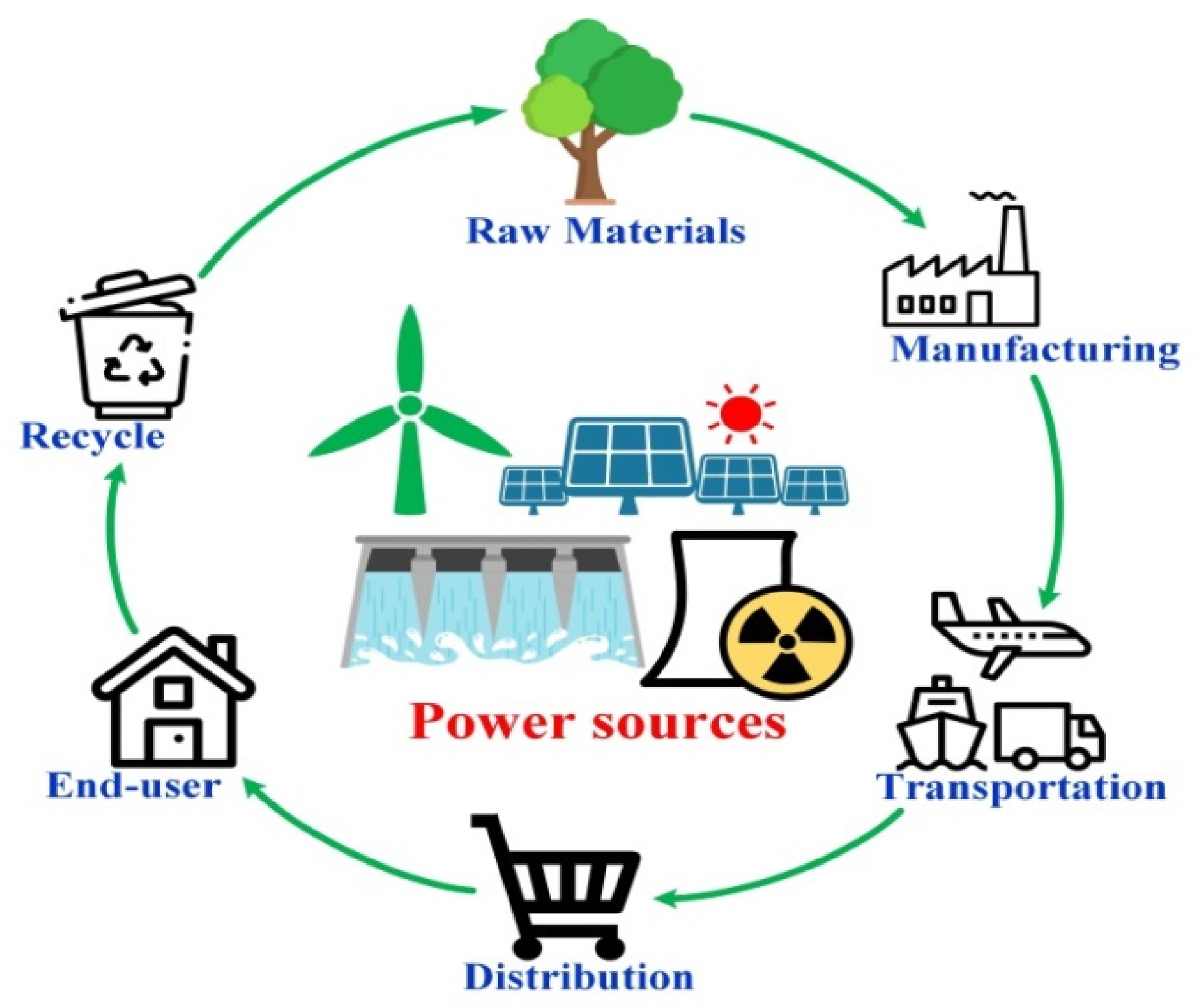
Currently, RESs and nuclear energy options are being considered for hydrogen production through water electrolysis. Indeed, to assess the viability of using these sources to supply electrolyzers from the GHG emissions point of view, a life cycle analysis (LCA) for each candidate source has to be performed. This LCA enables us to consider the environmental impacts of extracting raw materials from use to recycling and reprocessing by reporting them at a cost in CO2 equivalent per kilowatt-hour produced (g CO2 eq/kWh).
The principle of LCA is depicted in
Figure 2. Based on the available data provided by ADEME (environment and energy management agency) [
46] and IPCC (intergovernmental panel on climate change) [
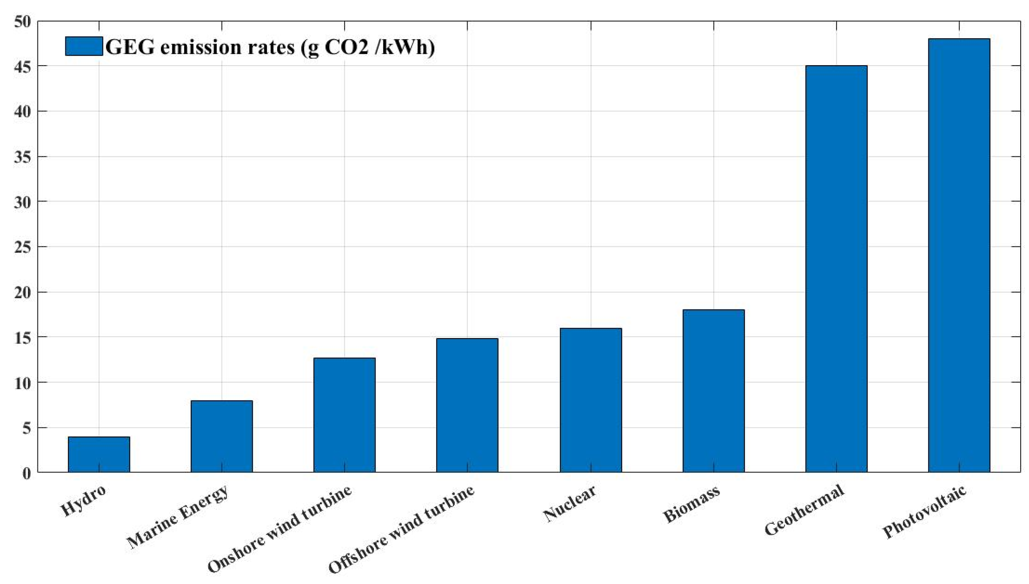
47], an LCA has been carried out for different power sources, including wind turbines, photovoltaic, hydro, marine energy, nuclear, biomass, and geothermal. The GHG emission rates expressed in (g CO
2 eq/kWh) are provided in
Figure 3. From
Figure 3, it appears that hydroelectricity features the lowest GHG emission rate (around 6 g CO
2 eq/kWh) compared to the other sources. The other sources such as marine energy, wind turbine (both offshore and onshore), nuclear, and biomass present GHG emission rates lower than 20 g CO
2 eq/kWh. By comparison, photovoltaic systems suffer from having higher GHG emission rates (around 48 g CO
2 eq/kWh) due to recycling issues and the use of unsustainable materials and toxic substances [
37]. The usual power sources for hydrogen production such as natural gas and coal show a GHG emission rate of 469 and 1001 g CO
2 eq/kWh, respectively. Thus, hydro, marine (tidal, wave), wind turbine, nuclear, and biomass energy are the most suitable low-carbon sources to feed electrolyzers and consequently ensure low GHG hydrogen production [
44,
48]. However, Although PV panels have a higher GHG (less than 50 g CO
2/kWh) compared to other renewable energy sources such as hydro (less than 5 g CO
2/kWh), this source has a lower GHG than that related to fossil fuels (natural gas and coal). For this reason, hydrogen production pathways based on PV systems are considered in many projects, as highlighted in [
7,
39].
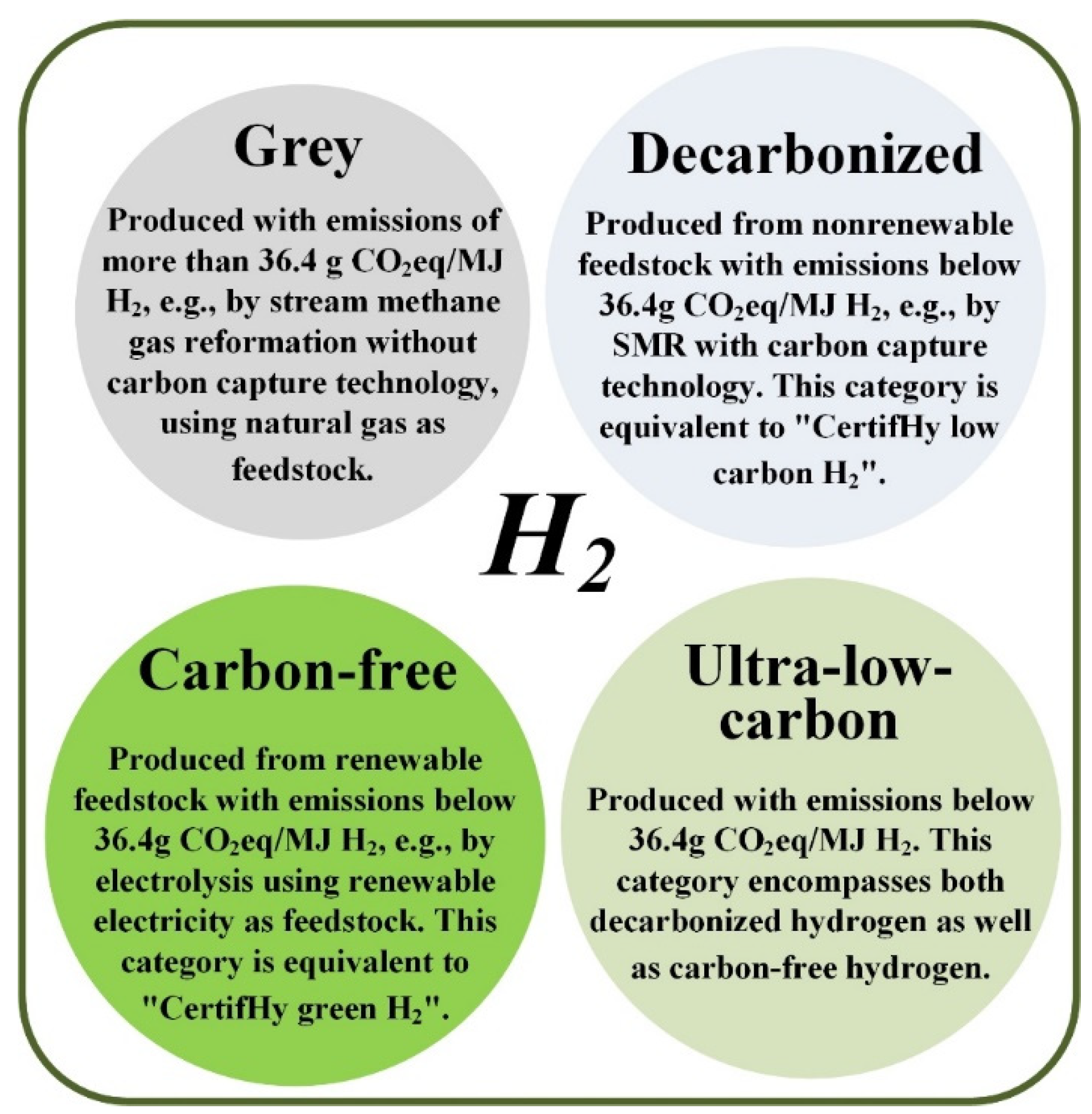
Based on the production methods, different colors are assigned to label hydrogen. Recently, a guarantee of origin (GO) for hydrogen has been introduced. GO schemes are in place in Europe concerning renewable electricity. In some countries they are also in place for electricity obtained from combined heat-power (CHP) plants, renewable heating and cooling, and biomethane. This classification considers emissions in g CO
2 eq/MJ H
2. The so-called Grey hydrogen is fabricated whose emissions exceed 36.4 g CO
2 eq/MJ H
2, as an example, it occurs in steam methane gas reformation, using natural gas as feedstock, without carbon capture technology. Decarbonized hydrogen is the hydrogen obtained by nonrenewable feedstock with emissions lower than 36.4 g CO
2 eq/MJ H
2, it can be obtained by SMR with carbon capture technology. Non-polluting hydrogen encompasses the hydrogen obtained from renewable feedstock having emissions lower than 36.4 g CO
2 eq/MJ H
2, as in the case of electrolysis using renewable electricity as feedstock. Finally, the Ultra-low-carbon hydrogen is processed with emissions lower than 36.4 g CO
2 eq/MJ H
2. This class includes decarbonized hydrogen and carbon-free hydrogen; a schematic representation of this kind of hydrogen is given in
Figure 4 [
49].
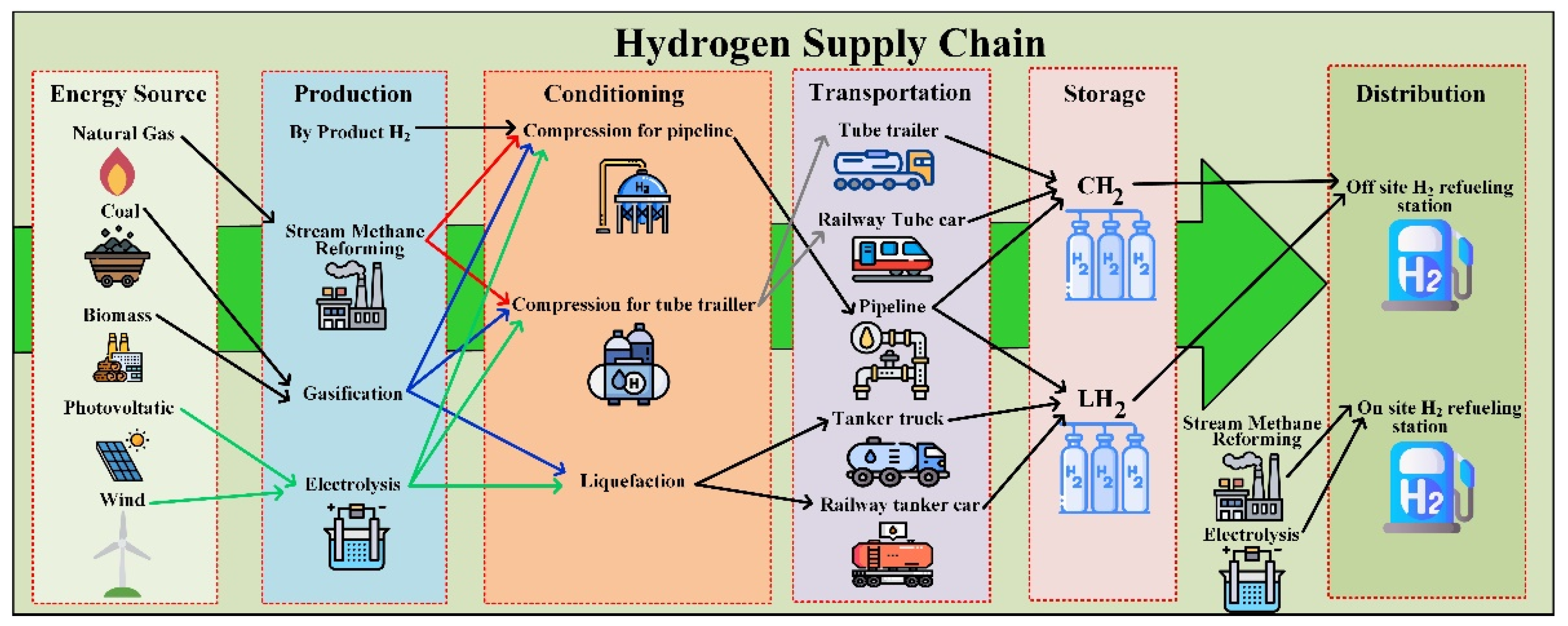
The color defined by Certify depends on the technology adopted for H
2 production. Actually, in the hydrogen supply chain, different solutions are still present. The supply chain of hydrogen is formed, based on primary energy sources, by production, conditioning, transportation, and storage, and then it is distributed to the end-users. Concerning the primary energy sources, hydrogen can be obtained by natural gas, coal, biomass, and RES as solar or wind plants. Among these sources, natural gas, coal, and biomass need to be imported from overseas; wind and photovoltaic generation can occur locally or in the neighborhood lowering the transportation losses. The production can be performed as a byproduct from chemical processes, by steam methane reforming, gasification, and electrolysis. In this last case, electricity delivered by RES allows a carbon-free generation. Before transportation, conditioning is required. Tube trailers or pipelines need compression (GH
2), in addition, the cryogenic liquid form can be used (LH
2). The state of hydrogen also depends on transportation: a tanker truck or a railway tanker car allows liquid transportation but if the storage is performed by compressed gas, a vaporizer is required. The distribution is is the form of refueling station either in on-site or off-site form; it should be noted, however, that the on-site refueling stations are supplied directly by electrolysis or steam methane reforming avoiding the previously described chain with corresponding losses [
50]. A schematic diagram of the hydrogen supply chain is given in
Figure 5.
A subset of this chain can be used to define cells for the hydrogen supply chain for H
2 production at the urban or rural level. As an example, ref. [
51] considers a node whose energy inputs are natural gas, biomass, and electricity coming from the grid; they are converted into hydrogen and CO
2 by a steam methane transformer supplied by a digester. Besides, an electrolyzer produces hydrogen delivered to an H
2 network. Also, the produced CO
2 is driven through a dedicated network. A suitable set of nodes can fulfill the demand in wide areas.
3. Overview of the Main Considered Hydrogen Applications: Present and Future
This section aims to present the main considered hydrogen applications (including present and future), leaning on practical applications and example projects. It encompasses an overview of hydrogen applications, considering a clean and sustainable hydrogen production pathway based on water electrolysis whose electric energy is supplied by renewable and nuclear power sources.
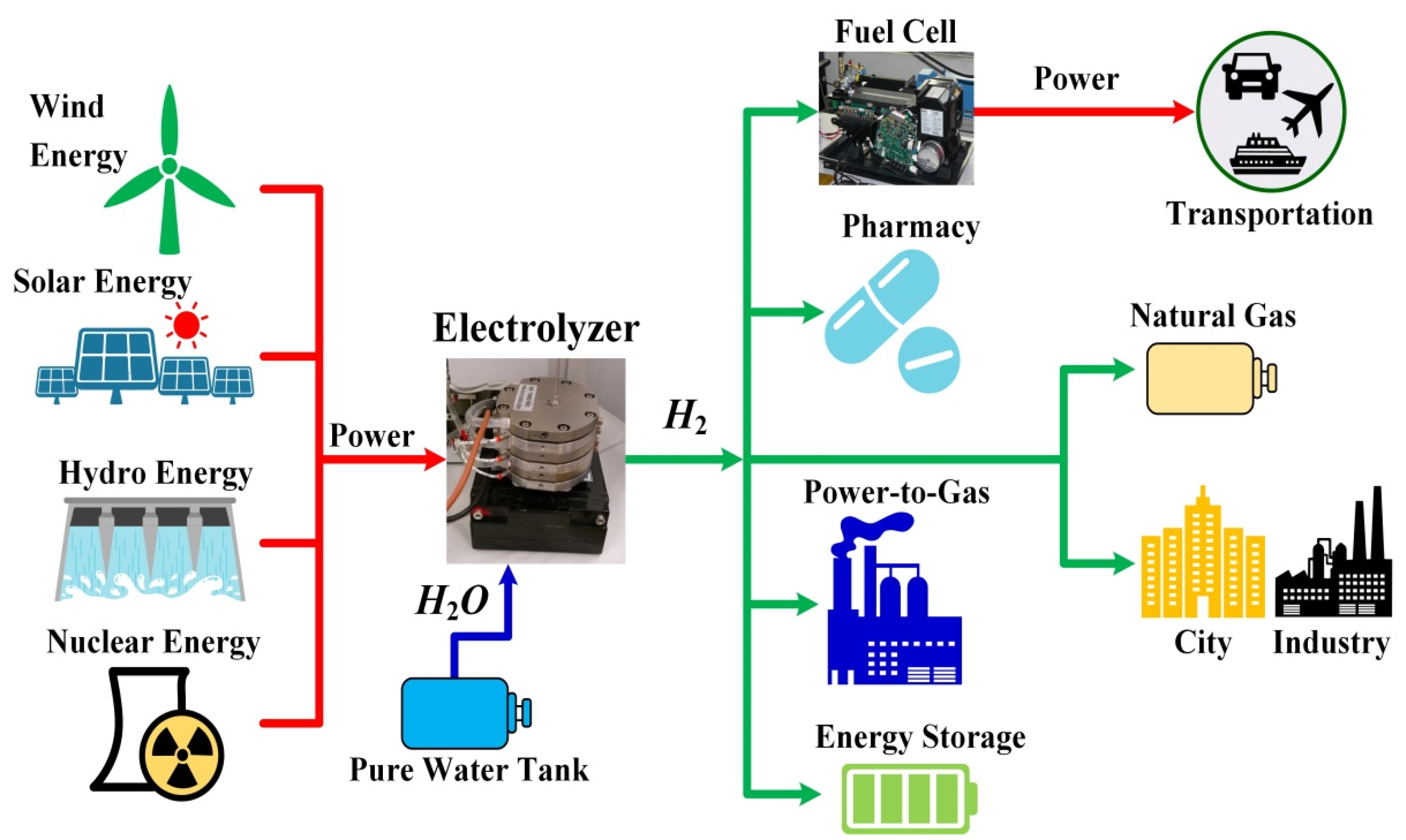
Figure 6 shows a schematic representation of hydrogen applications considering renewable and nuclear power sources. In this section, the different applications are gathered and presented as follows:
- (1)
Clean and competitive hydrogen-based mobility;
- (2)
Stationary applications and cogeneration for the built environment;
- (3)
Electricity production;
- (4)
Industrial applications.
Figure 6 summarizes the main sources of electric energy to be used for hydrogen production by electrolyzers (left side) and the load’s use of hydrogen. Wind, solar, and hydro are recognized as clean and sustainable sources (resources that are naturally replenished on a human timescale). Solar panels produce directly electric energy, wind and hydro plants turbines are coupled to rotating generators. Nuclear plants deliver electric energy by turbines driven by steam generated by the nuclear plant. In this last case, however, nuclear fuel produces waste that must be treated and suitably stored. Electric energy after conversion is transformed into a DC value for supplying electrolyzers. They transform the electric energy into hydrogen requiring water only in addition. Different loads can be used depending on applications. Fuel cells can transform hydrogen again into electric energy powering transportation systems. Hydrogen is used in pharmaceutical industries as it is or injected into grid gas. Finally, hydrogen represents a solution to store energy, shaving the peak production by RES. The many uses of hydrogen shown in this figure do not produce direct CO
2 emission either during production (the electrolyzer gives as output only O
2 and water) or during the utilization since it does not contain carbon atoms. All the applications discussed in the following in detail are hence carbon-free and aim to show how hydrogen can be seen as a clean and sustainable energy vector for the energy transition.
3.1. Clean and Competitive Hydrogen Based Mobility
3.1.1. Fuel Cell Powered Electric Vehicles
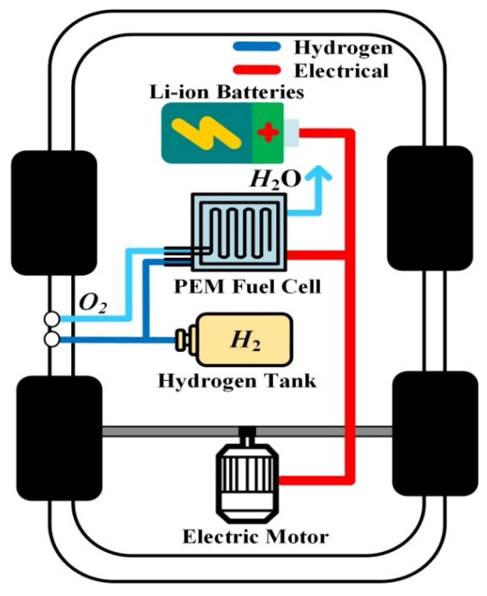
Currently, three main FCEVs are available on the market for sale and leasing: Toyota MIRAI second generation (2020–…), Honda CLARITY (2016–2021), and Hyundai NEXO (2018–…). Among these cars, only the production of the Honda CLARITY ended in August 2021. These FCEVs are based on a standard powertrain composed of a PEMFC, high-pressure H
2 tanks (around 700 bar), lithium-ion (Li-ion) batteries, electric motors, and power electronics to manage the operation of the FCEV [
52]. PEMFC is a technology perfectly fit for transportation applications because of its benefits from the high-power density and low-temperature operation point of view. Besides, it is supplied in hydrogen from tanks and air taken from the atmosphere. So, the autonomy of the PEMFC strongly depends on the onboard hydrogen storage capacities that can vary from an FCEV to another. On the other hand, the Li-ion batteries embedded in the FCEV have several functions [
53]:
- (1)
To extend the driving range of the FCEV.
- (2)
To protect the PEMFC against degradations (shortening its lifespan) during dynamic operations (i.e., acceleration mode).
- (3)
To enhance the performance of the FCEV.
- (4)
To absorb the energy during deceleration and regenerative braking phases.
An example of an FCEV powertrain is shown in
Figure 7 with the main components, except the power electronics part.
Table 1 shows a summary of the main specifications of the three FCEV commercially available. Based on
Table 1, Hyundai NEXO gives the largest driving range (around 666 km) based on the WLTP (Worldwide Harmonized Light Vehicles Test Procedure) driving cycles. This large driving range can be explained because of the onboard hydrogen storage capacities (higher than the other FCEVs). However, Honda CLARITY features the best performance in reaching 100 km·h
−1 in 8.1 s over Toyota MIRAI II and Hyundai NEXO (>9 s). Although current FCEVs are mainly based on PEMFC/Li-ion batteries configuration, other configurations have been investigated in research, such as PEMFC/Supercapacitor [
54], PEMFC/Battery/Supercapacitor [
55], and more recently PEMFC/Li-ion capacitor [
56].
The use of hydrogen is encouraged by its advantageous energy content; indeed, 1 kg of H2 is roughly equal to 1 gal (3.7854 kg) of gasoline (in BTUs).
Both gaseous and liquid hydrogen can be considered for vehicles with different supply systems. Hydrogen under the gaseous form is transferred to the refueling station through a tube trailer, then it is compressed and finally stored locally, and it is piped to a dispenser for refueling vehicles. Hydrogen under the liquid form is transported to a refueling station through tanker trucks, buried underground to store it, vaporized in the above-ground vessel, compressed and stored locally, and then it is piped to a dispenser for refueling vehicles. Both solutions require safety precautions.
It is important to point out that many organizations exist dealing with codes, standards, and guides. For instance, the hydrogen tools portal [
60] is pursuing the worldwide dissemination of over 300 hydrogen and fuel cell standards including linked documents. International Fire Code (IFC) addresses hydrogen applications: in particular are of interest: IFC Section 2309: hydrogen Motor Fuel Dispensing and Generation Facilities, IFC Chapter 50—Hazardous Materials-General Provisions, IFC Chapter 53—Compressed Gases, IFC Chapter 58—Flammable Gases and Flammable Cryogenic Fluids and International Fuel Gas Code (IFGC) Chapter 7—Gaseous Hydrogen Systems.
The NFPA 2 (2016 Edition), Hydrogen Technologies Code, furnishes elementary precautions for the production, installation, storage, piping, use, and handling of hydrogen in pressurized gas under gaseous (GH2) or cryogenic liquid (LH2) form. It addresses all fundamental conditions of hydrogen storage, use, and handling. The code can be applied to gaseous and liquefied hydrogen in–Storage–Transfer–Production–Use. It includes stationary, portable, and vehicular infrastructure applications. Fundamental requirements for–Storage–Piping–Installation–Handling–Generation are finally provided.
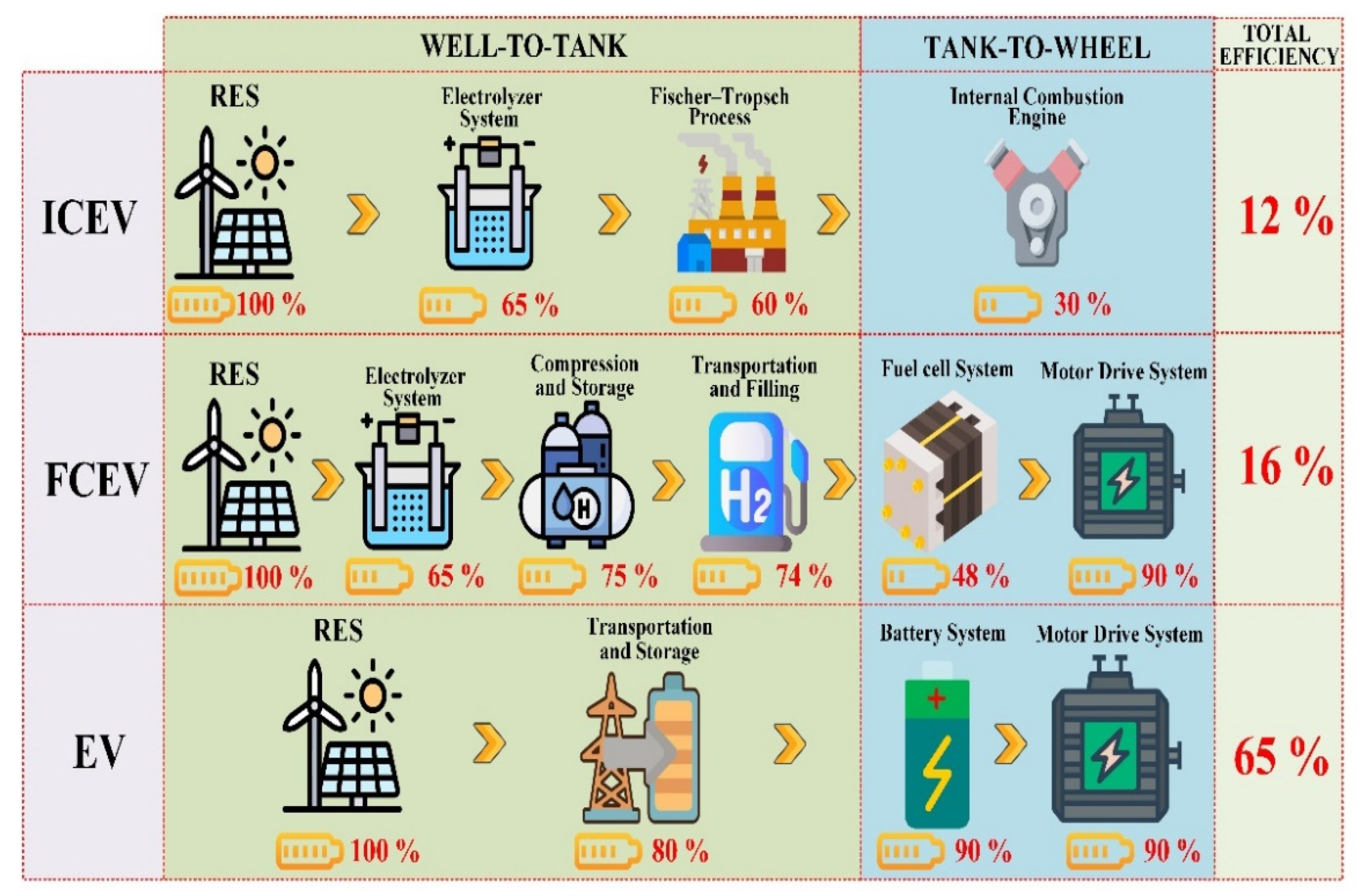
To conclude about the development of FCEV, an overview of energy conversion efficiency (from production through use) of three types of powertrains (internal combustion engine (ICE) vehicles, FCEVs, and electric vehicles (EV)-based batteries) is shown in
Figure 8. In the case under study, RESs have been considered to charge electric vehicles, to generate hydrogen through water electrolysis, or fuel through the Fischer–Tropsch process for ICE vehicles. Besides, for the electrolyzer (68% stack efficiency), fuel cell (50% stack efficiency), and motor drive system, the energy efficiency of power electronics (5% losses) has also been considered to get closer to the real system [
36,
50]. By multiplying the different energy efficiencies at each conversion step, the total energy efficiency has been determined. It can be noted that ICE vehicles feature a poor total energy conversion efficiency (around 12%). Furthermore, for FCEVs, due to an important number of energy conversion steps, the total energy conversion efficiency is very low (around 16%). To increase the overall energy conversion efficiency of FCEVs, further efforts must be made for hydrogen technologies (electrolyzer, storage, fuel cell) and power electronics with the objective to compete with EVs that exhibit a better energy conversion efficiency (around 65%). Indeed, a better energy conversion efficiency (4 times that of the FCEVs) can be obtained since the energy conversion chain requests fewer energy conversion steps.
3.1.2. Hydrogen-Powered Boat
The world’s first hydrogen-powered vessel known is the “Energy Observer” that was launched in April 2017 with the purpose to achieve a trip around the world being in total energy autonomy without GHG emissions. This vessel, which was designed and developed in cooperation with engineers from the French Company CEA-Liten (Grenoble, France), can be seen as a “floating laboratory”. The main objective is to assess and optimize the effectiveness of an embedded power grid relying on the coupling of various RES (wind, solar, hydropower), short-term (Li-ion batteries), and long-term storage based on hydrogen generated on board from seawater electrolysis [
61]. The used solar panels are manufactured by the Company SunPowerCorporation (San José, CA, USA) and have the particularity to be bifacial. In other words, bifacial solar panels enable producing up to 30% more energy because of the reverberation on the white surfaces of the vessel hull and the sea. Besides, thanks to the heterojunction, the solar panels combine two types of silicon (crystalline and amorphous silicon), enabling the efficiency improvement of the solar panels (around 24%). On the other hand, different technologies have been employed for wind energy, such as two vertical axis wind turbines, traction wings, and then vertical axis wind thrusters. Finally, the hydropower is generated through two reversible electric motors allowing 4 kWp each when the vessel is located in an area with high ocean currents. The main specifications of the Energy Observer are reported in
Table 2 and the embedded power grid is shown in
Figure 9. However, the desalinization process and the compressor do not appear in this figure to make it more straightforward.
In addition to the short-term storage based on Li-ion batteries, long-term storage relying on hydrogen is used to lengthen the vessel’s autonomy during the night or when the meteorological conditions are not suitable to produce energy through RES. The hydrogen pathway is composed of a desalinization and purification process to treat the seawater, an electrolyzer to generate hydrogen from the treated seawater, and electricity from RES, a compressor to make suitable hydrogen pressure before storing it in eight high-pressure tanks. As highlighted in [
62], hydrogen system (electrolyzer, compressor, fuel cell) has a low energy efficiency (around 30%) compared to Li-ion batteries (around 90%). However, hydrogen storage offers more benefits in storing a large amount of energy and is available when power demands are requested.
Recently, other hydrogen-powered boats have been developed, such as a catamaran from the Swiss Company AQUON (Zürich, Switzerland) [
63], a yacht from the French Company HYNOVA (Roquevaire, France) [
64], and a vessel from the Group Tender ONE [
65]. Among these three types of boat, only the catamaran owns a hydrogen production process onboard supplied by 70 m
2 solar panels. The seawater treated through desalinization and purification devices is employed to fulfill the water electrolysis process. The yacht embeds three hydrogen tanks with a single PEMFC; while for the vessel, five hydrogen tanks with three PEMFC form a multi-stack system [
66]. As a result, to refuel the hydrogen tanks, a hydrogen refueling facility is needed (the tanks can be refueled in 15 min). The vessel also includes solar panels for auxiliary power. Like FCEVs and the Energy Observer, the three types of the boat include the use of batteries. However, in these cases, LiFePO4 (Lithium Iron Phosphate) technology is used for safety reasons. The PEMFC or the multi-stack PEMFC provides the average power requested to propel the boat. In contrast, the LiFePO4 batteries allow a response to power peaks. Besides, the combination PEMFC/LiFePO4 batteries enables the performance of the boats to be enhanced while optimizing the lifespan of the PEMFC that may be damaged during dynamic operations [
53]. The specifications and the propulsion principle of the hydrogen-powered yacht and vessel are respectively given in
Table 3 and
Figure 10. The vessel has several applications such as military, police, coastguard, and rescue services.
3.1.3. Hydrogen-Powered Train
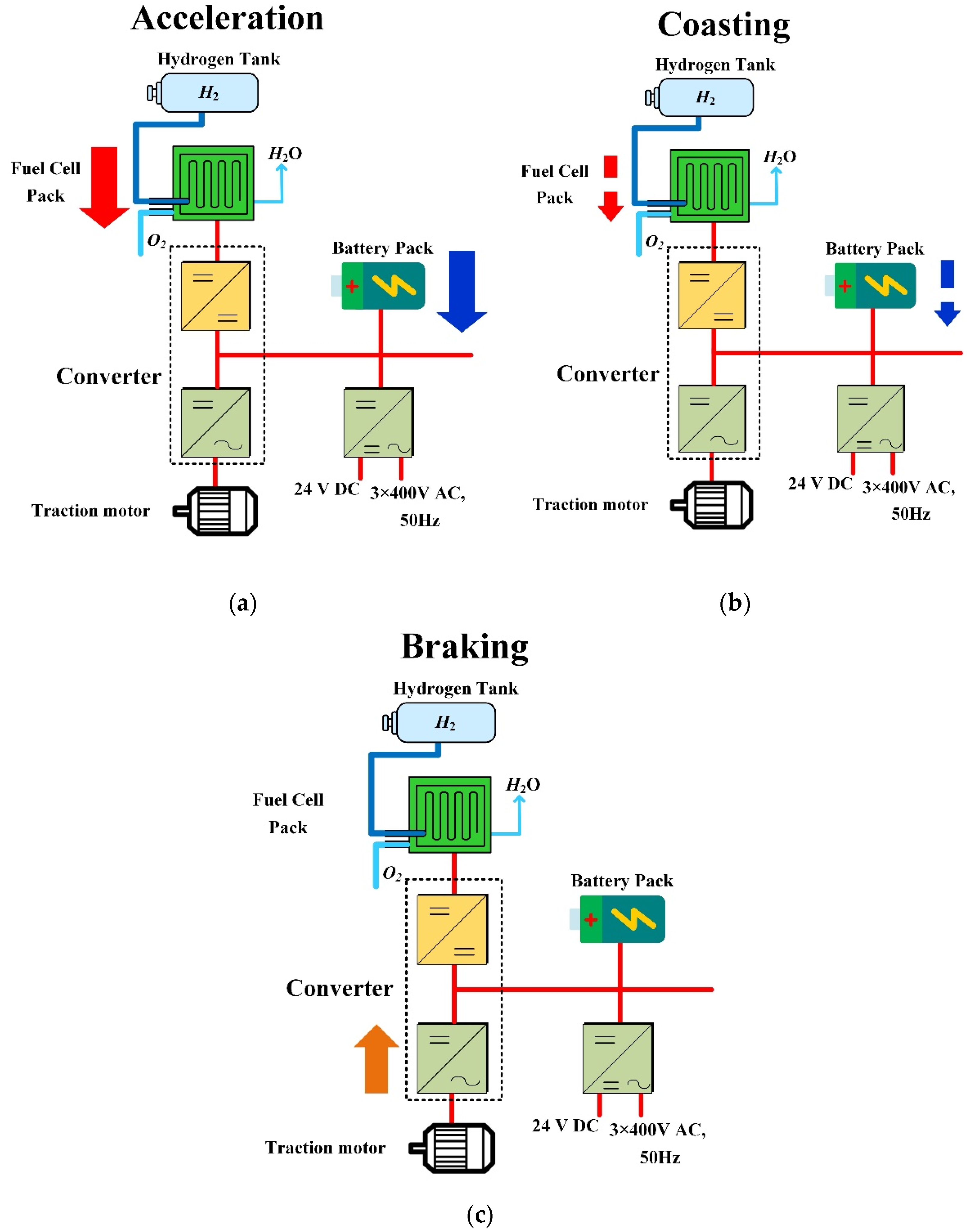
The world’s first hydrogen power train called “Coradia iLint” manufactured by Alstom has entered service in 2018 in Lower Saxony (Germany) [
67]. The train is powered by a PEMFC supplied by high-pressure tanks (around 350 bar) located both on the roof of the train. It also includes a Li-ion battery pack, converter system, and electric traction motors. The Li-ion battery pack enables the storage of the power surplus from the PEMFC and absorbs the kinetic energy during regenerative braking phases. Besides, the batteries directly supply the electrical traction motors during steady-state operations and allow the acceleration of the train to be boosted if needed. The electrical supply of the train is optimized by an energy management system relying on algorithms. Three different operation phases are met, namely, acceleration, coasting, and braking. The energy management principle for these three operations is depicted in
Figure 11. The train can run about 1000 km with the onboard hydrogen storage that competes with diesel-powered trains. Its speed can reach 140 km.h
−1. Due to the first successful tests in Lower Saxony, other hydrogen-powered trains are currently being developed for some countries in Europe such as France, UK, Netherland, Austria, Poland, and Germany (extended to six additional federal states like Rhineland-Palatinate, Baden-Württemberg, Saxony, Thuringia, Berlin, and Brandenburg) [
67].
3.1.4. Hydrogen-Powered Aircraft
The aviation sector, including passenger air travel, freight, and military operations, represents between 2% and 2.5% of the global GEG emissions. Indeed, most aircraft are powered by jet gasoline, even if some are supplied with biofuels. Due to the growing development of passenger air travel, GEG emissions from the aviation sector have been increasing over the last decades. However, the aviation sector has been strongly impacted by the Covid-19 pandemic, which has drastically slowed down passenger air travel and GEG emissions [
68]. On the one hand, compared to the automotive sector, the aviation sector’s decarbonization is complex because of the large-scale aircraft and their high range between takeoff and landing. On the other hand, some design concepts have emerged, such as the zero-emissions (ZEROe) aircrafts powered by hydrogen from the Airbus Company (Blagnac, France). Airbus has planned to develop three ZEROe aircraft concepts that might enter service by 2035 [
69]:
- (1)
Turboprop concept: this aircraft looks like the ATR72 or the Bombardier Q400 currently employed mostly in regional networks. It will feature a range of around 1000 nautical miles (around 1852 km) and be powered by two particular hydrogen turboprop engines. It shall carry just fewer than 100 passengers and it is specifically designed for regional feeder routes.
- (2)
Turbofan concept: this aircraft can carry up to 200 passengers and features a range of 2000 nautical miles (around 3704 km). It looks like the commercial planes that we can see flying in the world nowadays. The range is suitable for most routes as the average distance traveled by most current flights is around 1240 nautical miles or 2300 km.
- (3)
Blended-wing body concept: This aircraft can carry up to 200 passengers and cargo as well. Because of its wide fuselage, it might offer multiple options for hydrogen storage and for cabin layout too. Among the three concepts, the blended-wing body concept is by far the most interesting, with the possibilities offered for hydrogen storage and passengers.
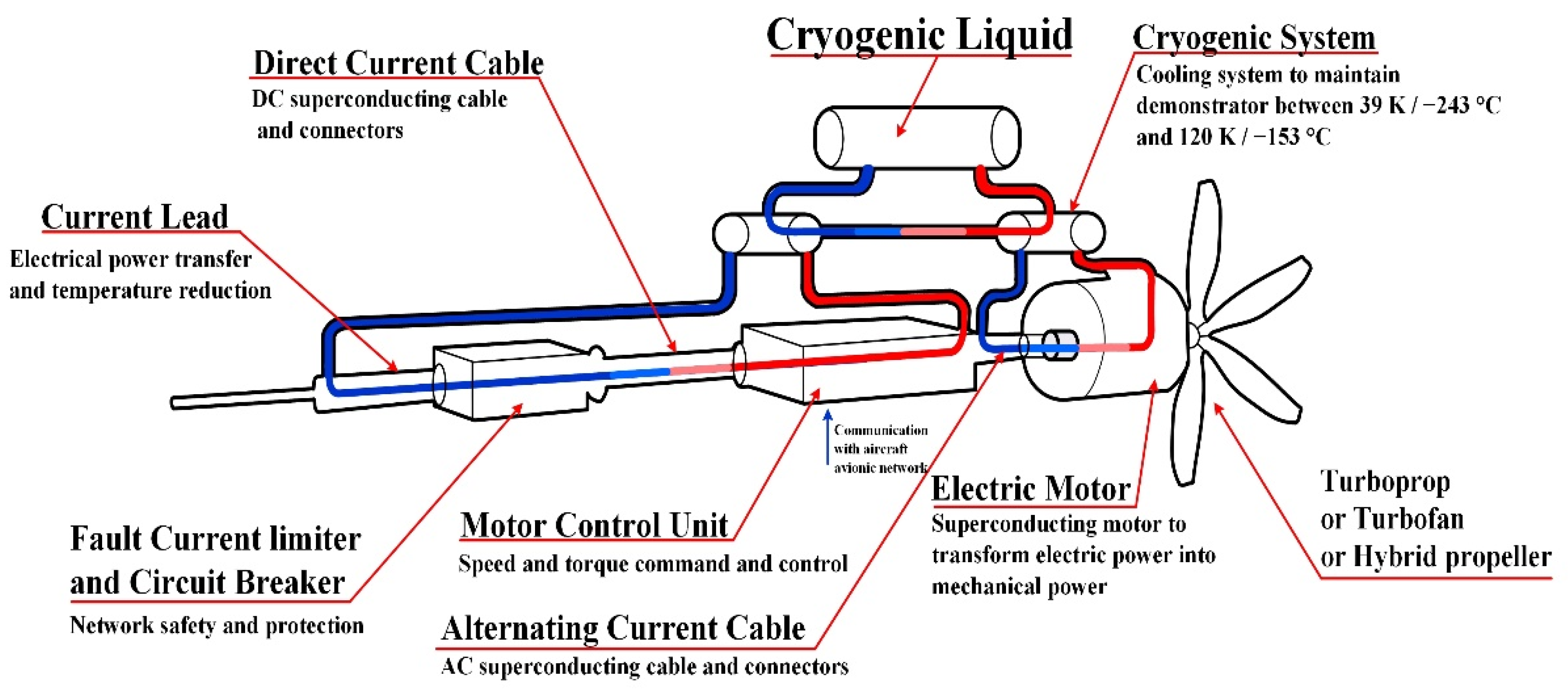
The modified gas-turbines engines will be powered by hydrogen combustion. The use of liquid hydrogen has been adopted to power these aircraft because, in liquid form, hydrogen features a higher energy density per volume than hydrogen storage based on high-pressure tanks commonly used for automotive, boat, and train applications. However, to maintain hydrogen under the liquid form, it needs to be stored cryogenically at −253.15 °C. To achieve this goal, Airbus is currently developing the ASCEND (Advanced Superconducting and Cryogenic Experimental powertraiN Demonstrator) system. The main aim of the ASCEND concept is to prove the feasibility and application of a superconducting powertrain and provide recommendations for onboard aircraft application. The use of superconducting and cryogenic technologies allows halving the weight of the components and electrical losses and reducing voltage below 500 V; a schematic representation is given in
Figure 12 [
70].
In summary, the range offered by the hydrogen-powered aircraft is much smaller than the range provided by current aircraft powered by jet fuel. Indeed, the turbofan aircraft has a range of around 2000 nautical miles against 4761 nautical miles for jet fuel-powered aircraft. Despite the hydrogen-powered aircraft concept being ambitious, there is still a need for long-haul aircraft using jet fuel to connect distant cities. As a result, further research and development are requested so that the hydrogen-powered aircraft can compete with jet fuel-powered aircraft from the range point of view [
70]. Finally, airports will request a consequential amount of hydrogen in transport and refueling infrastructures to converge towards the requirements of daily operations. The same issues are also met for the other transportation sectors. Thus, support from the governments will be the key to reaching these ambitious goals, by increasing, for example, research and development funding, and encouraging the use of sustainable fuels and the renewal of aircraft fleets.
3.2. Electricity Production
Hydrogen can play the role of enabler in the expected future improvement of the energy system, leading to decarbonized power generation [
71]. The decreasing cost of wind and solar sources encourages power generation by renewables even if it needs a further increase [
72]. One drawback of using renewables for such generation is the energy system stability assessment due to the inherent variable and intermittent generation; as shown in [
73], in the case of distributed generation, the limited inertia of the rotating generators can increase the frequency variations of the voltage delivered by the grid frequency in correspondence with significant variations of the load. This issue is of particular interest for weak grids. The usage of energy storage systems for supporting the dynamic of the grid supports is recommended. A solution to stabilize the grid so that it is able to absorb excessive power generation, and to provide energy when power generation must be compliant with decarbonization targets (meaning avoiding generator turn-off) is given by hydrogen as a storage system [
74]. Moreover, a coupling among different sectors aimed to connect the building heating, industry sectors, and transportation, as energy consumers with the power generation distribution system, can give more engaging options to assure stability. Hydrogen can provide a solution for sector coupling and the opportunity to store energy at a large scale to support the increase in renewable energy generation systems. By this coupling, power is not necessarily retrieved in the same location where it must be employed, or when it is requested [
75,
76].
A small-scale solution is power-to-heat technology; it employs an overproduction from renewables for generating heat by an electrode boiler or for heat pumps; it can supply the existing heating infrastructure directly [
77]. Even if this technology is revealed to be highly efficient in enabling the simultaneous decarbonization of the building segment, it does not give a satisfactory balance to the energy system since the production excess of renewable power usually does not suit the heating demand. The power-to-gas solution offers more freedom to combine sectors with benefits for increasing stability. Hydrogen generated by electrolysis offers the same flexibility as natural gas, avoiding CO
2 emissions, and the existing infrastructures can be used. Besides, it is competitive with batteries for large amounts of energy and a long time period. On the other hand, the use of batteries or supercapacitors is also required as complimentary storage for a fast response of compensating systems [
78,
79].
Hydrogen can be stored for a long period and at a large scale at a competitive cost, with respect to traditional large-scale energy storage systems, such as pumped hydro. However, reconversion is still penalized by a lower efficiency (approximately from 50% to 60%); it is less expensive than some alternative storage solutions. It should be remarked that reconversion is sometimes not required; in this case, the hydrogen, once stored, can be used directly as a fuel for heating, transport, and industry.
Finally, hydrogen can allow transporting power to demand areas in gaseous or liquid form, via pipelines or ships when renewable generation always outstrips the energy demand in regions in which it is generated [
80].
3.3. Industrial Applications
The role of hydrogen in industry has been acknowledged in the last two decades [
81], and studies in the literature have proposed several uses of hydrogen in the industry [
51,
82,
83]. Nowadays, it is well recognized that hydrogen can help industries by giving them decarbonizing options. Two main areas are recognizable: industry heat and industry feedstock [
71].
The industry heat sector encompasses six energy-intensive industries that exploit about 60% of the final energy: aluminum, cement, iron, and steel, (petro)chemicals, refining, and pulp and paper. In the next future, seven ways to decarbonize industry heat are envisaged: (1) Demand-side measures consist of diminishing the requests for primary resources by an increase of diffuseness based on recycling, reuse, or products substitution; (2) Energy efficiency rules that are focused on adapting production equipment and devising suitable technologies to lower energy use; (3) Electrification can be redesigned where it is technically feasible from a technical point of view and affordable aiming to replace fossil fuel with heat produced by RES; (4) Biomass can be adopted, replacing fossil fuel where available; (5) Hydrogen can replace fossil fuel by adopting ultra-low-carbon hydrogen; (6) Carbon capture technologies can be developed based on equipping carbon capture and storage (CCS) and carbon capture and utilization (CCU) processes; (7) Additional modernism, i.e., the development of breakthrough processes (mainly electrochemical production processes), can lower emissions.
Among the above-mentioned options for fuel substitution (items from 3 to 5), electrification can be considered to be the primary solution to decarbonize industrial processes considering the low-grade and medium-grade heat sectors. Unfortunately, electric heaters, boilers, and furnaces show poor efficiency features increasing temperatures; their use may need significant adaptations in production processes. On the other hand, for industrial processes occurring in the high-grade heat sector, hydrogen may benefit from generating high temperatures using process setups similar to those already in use today.
Since each industrial sector needs dedicated, cascaded heat and pressure ranges, it is necessary to consider them separately for assessing decarbonization technologies. The solution mainly depends on the cost and, consequently, on electricity prices related to hydrogen production. Local conditions such as, for example, the accessibility of clean-energy hydrogen or the one of CCS or biomass are also critical decision factors [
84,
85].
Currently, hydrogen cannot be recognized as cost-competitive compared to current fuels in the majority of industries. However, hydrogen will most probably substitute natural gas; hence, a viable working hypothesis for a break-even cost would be the natural gas cost summed with the cost for CO2 proofs a cost level that hydrogen currently surpasses. As a consequence, hydrogen could be used firstly in higher-value segments (e.g., transportation). In any case, hydrogen can complement electricity. For instance, users with wind power plants can also produce hydrogen when the power supplied exceeds demand during the day. Among high-grade heat segments, hydrogen is revealed to be the most cost-efficient when it is already employed as supply in industrial processes or derived as a byproduct. In the chemical sector (whose emissions are about 20% of all CO2), hydrogen allows production to be decarbonized with a significant reduction of retrofit investments and process variations compared to electrification.
Regarding the industry feedstock, most of the currently produced hydrogen is employed to obtain other materials thanks to its chemical property rather than energy properties. Most of the hydrogen employed in these industrial sectors (about 95%) is given by natural gas (SMR without CCS) or byproduct, resulting in the well-known grey hydrogen. For this reason, the decarbonization of hydrogen exploited in these sectors is highly relevant. Switching from grey hydrogen to ultralow-carbon hydrogen is expected to allow companies to decrease emissions either substantially or almost entirely. During this transition period, hydrogen coming from byproducts of electrolysis could be complementary to hydrogen obtained from SMR with or without CCS.
Besides, low carbon hydrogen use will be boosted in the next future by new opportunities, mainly by carbon capture and utilization (CCU) [
84]. Hydrogen can replace coal used as a reducing agent to be adopted in the steelmaking process. Industries could also employ it together with captured CO
2 or CO
2 from biomass, avoiding or minimizing fossil fuel feedstock to produce hydrocarbon-based chemicals (methanol and derived products). In the steel industry, there are three main options to exploit hydrogen so that steel production from the iron can be decarbonized. The first option consists of transforming biomass into coke; replacing fossil coal in the blast furnace route. However, this operation is feasible if biomass is obtainable at a relatively cheap cost and available in sufficient quantities and qualities. It also needs a design of different furnaces affecting initial investment and cost making it difficult for the adoption of such solution for large-scale steelmaking. The second employs CCS on the blast furnace; it is viable only if carbon storage is available, implying an energy penalization. In addition, CCS is not always accepted from a political point of view and could lead to societal discussion, considering that CO
2 is still produced even if it is not generated. The third option considers commutate iron production to Direct Reduced Iron (DRI) plants where natural gas is replaced flexibly with hydrogen and is used in electric arc furnaces for steelmaking. Hence, decarbonizing steel is a crucial step forward to total decarbonization [
86,
87].
Carbon capture and usage (CCU) can represent a workable substitute for chemicals, and for hydrogen, the captured CO
2 can be used to deliver high-value chemicals currently based on fossils. On the other hand, CCU cannot be assumed as a final solution since the total emission of industry carbon far surpasses the carbon that can be recycled back. Besides, the main impediments to making more hanging CCU uptake today are related to the cost of the carbon capture process [
16,
88].
3.4. Stationary Applications and Cogeneration for the Built Environment: Combined Heat and Power and Tri-Generation
The feature of Fuel cells producing heat and power leads to two systems known as combined heat and power (CHP) generation or combined cold and power (CCP) [
89]. In the case of combined cold heat and power (CCHP) generation, the system is known as tri-generation [
7].
Particularly, CHP is intended as the generation of both heat and power delivered from a unique fuel source, aiming to exploit both products. In a traditional domestic CHP system, hydrogen by the prime mover produces electrical power giving heat during the process. The electricity can be used directly by home loads and, where possible, exchanged with the grid; besides, heat obtained during generation can be stored or exploited by domestic hot water or space heating. Obviously, the use of such heat improves system efficiency, compared to the traditional heat generation, increasing it from 20% to over 90%. The amount of improvement depends on the technology of the prime mover and the extent of waste heat utilization. A good efficiency implies a lowering of primary energy demand with a consequent reduction in emissions and cost; on the other hand, the thermal output is expected to be fully utilized [
90].
The tri-generation extends the concept of CHP by using the recovered waste heat for producing cooling output by suitable heat-driven cooling technology. By tri-generation technology applied to small-scale systems, up to about 15 kW, over 80% of fuel energy can be converted to usable energy. This solution is of particular interest when the cooling demand during the hot season almost balances the thermal demand during the cold season. Both CHP and tri-generation systems can be considered as decentralized energy generators; this gives some advantages compared to centralized generation, among which are: improved efficiency, losses lines reduction due to the reduction of transmitted power, reduction of primary energy demand, and CO2 emission.
Even if three prime movers are used in CHP, internal combustion engine, Stirling engine (or both combustion-based technologies), and fuel cells, fuel cells offer some advantages as higher electrical efficiency and silent operation. However, since their use is tied to the hydrogen supply, it is evident that the hydrogen availability can further enable this market [
89].
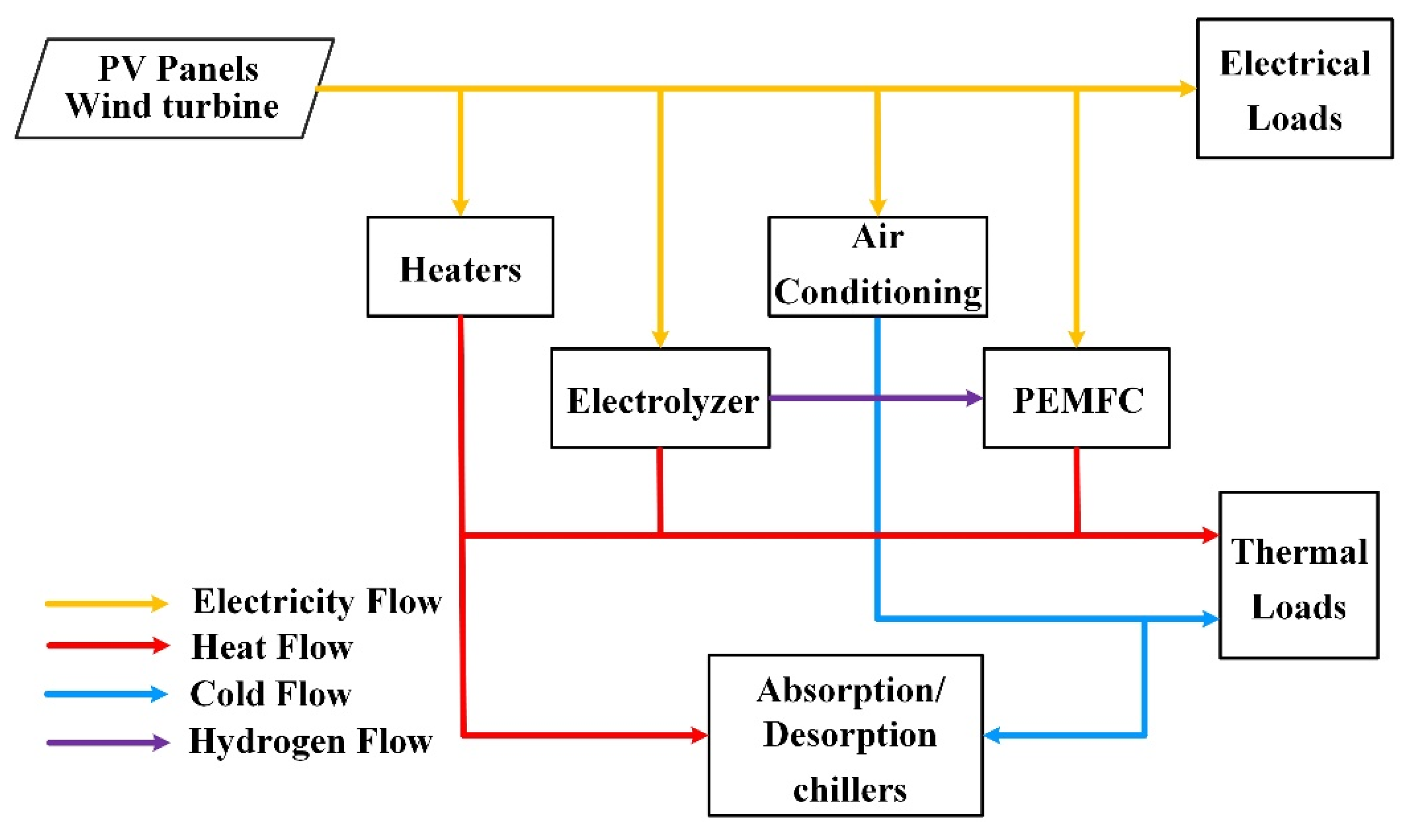
Figure 13 shows the working principle of tri-generation based on RES: the prime mover is a fuel cell exploited to thermally driven equipment to obtain cooling. Typically, when using a thermal sink in the cooling process, a heat pump is exploited; it contains two reactors, a condenser, and an evaporator. Electric energy produced by renewable sources, depending on its availability, can be exploited directly by heaters, by an electrolyzer for producing hydrogen supplying the fuel cell, or by a heat pump for air conditioning. Conversely, heat is exploited by thermal loads. Compared to the classic distributed cold, heat, and electricity, tri-generation equipped with fuel cells can diminish carbon emissions and improve energy efficiency. For example, the system’s overall efficiency reached 75% [
89], and 89% [
91], respectively. In isolated applications, fuel cell rejected heat can lessen the electrical power that is required by the compressor allowing it to store cold when a low demand occurs [
92], improving the system’s autonomy and efficiency.
3.5. Research Projects
Several projects have been launched to demonstrate the potential of hydrogen at an industrial scale [
7]. Some selected examples are described in the following. The DATAZERO project is focused on the energy needed by a data center; it is integrated with renewables. Besides, it considers as storage systems hydrogen, batteries, and supercapacitors. Fuel cells are employed for producing electricity [
93], and all systems loads/storage/supplies are interfaced by a DC bus connection. The “Underground Sun Storage” project is an Australian project; energy from RES (in particular wind and solar) is stored underground. Exceeding energy is converted by water electrolysis into hydrogen, then it is stored for different usages. The results demonstrated that the gas stored in underground tanks can tolerate hydrogen (up to 10% in gas) giving the capacity of balancing out the seasonal supplies of renewable energy [
94]. Issues related to the use of hydrogen to face the mismatching between system demand and load are also addressed in Denmark in Orsted [
95] mainly based on wind generation and in the United States in SoCalGas [
96] where the hydrogen produced by a solar electric system is converted into methane by a bioreactor directly.
The integration of an electrolyzer in MegaWatt scale in a wind farm is proposed in the HAEOLUS project [
97] developed in the north of Norway. The wind farm consists of 45 MW generators; a PEM electrolyzer of 2.5 MW provides hydrogen both for external consumers and for a Fuel Cell of 100 kW. The fuel cell system is connected to the grid providing energy by hydrogen in case the line capacity is not sufficient [
98]. Project HyCAUNAIS [
99] verifies a power-to-gas system through the methanation process. A 1 MW electrolyzer is interfaced with the grid and powered by wind energy; the hydrogen is converted into methane and injected into the natural gas grid; it is also joined with the production of bio-methane from landfill biogas.
For example, an industrial demonstration project based on storage solution using existing infrastructures, in Jupiter1000 [
100] renewable energy is transformed into gas performing a power-to-gas action so that a volumetric level ranging from 15% to 20% of blended hydrogen should be injected into the gas grid [
101].
Europe is currently developing micro-co-generation to be applied for residentials [
77]. The first European project using fuel cells applied to micro-co-generation is the ene.field project [
102]. Over 1000 residential micro-CHP fuel cells were installed from 2012 to 2017 across 10 European countries. The PACE project [
103] continues the activities of ene.field project. This project has a five-year duration from 2016; it considers 2800 micro-CHP fuel cells installed in more than ten European countries. In the ene.field project, an environmental life cycle assessment of micro-CHP fuel cells has been retrieved. As a result, from all the studied scenarios, greenhouse gas given by fuel cell co-generation is lower in comparison to gas boilers and heat pumps. The efficiency reached from these two projects was 60% and 95%, respectively.
4. The European Approach for Hydrogen Roadmap
The EU defined a strategic road map for hydrogen. It recognizes that hydrogen is enjoying new and rapidly growing attention throughout the world thanks to its inherent lack of CO
2 emissions and the possibility to be employed as a feedstock, fuel, or an energy carrier and storage and to be adopted in many possible applications across industry, power, transport, and buildings [
104].
Among several reasons to consider hydrogen, there is the clean energy transition: renewable electricity is expected to decarbonize a large amount of the energy consumption in the EU by 2050, hydrogen can help this process as a vector for storage energy coming from RES, alongside batteries, and transport, ensuring back up for seasonal variations; besides, it can connect production locations to more distant demand centers. The share of hydrogen among different forms of energy in Europe is expected to increase from the current value of less than 2% to 13–14% by 2050 [
105,
106]. Besides, investment in hydrogen can encourage sustainable growth and jobs in the new context of recovery due to the COVID-19 crisis.
On the other hand, at the moment, renewable-based and low-carbon hydrogen cannot be considered yet cost-competitive compared to fossil-based hydrogen. For this reason, a strategic approach is devised to harness all the opportunities associated with hydrogen. As an example, the EU industry developed an ambitious plan to reach 2 × 40 GW of electrolyzers by 2030 (40 GW located in Europe and 40 GW in Europe’s neighborhood with export to the EU).
The strategic roadmap includes the launching of the European Clean Hydrogen Alliance. It consists of cooperation between public authorities, industry, and civil society. Along with this, there is the Strategy for Energy System Integration, which includes hydrogen integration with renewable electricity, circularity, and renewable and low-carbon fuels at its core. The strategies aim to satisfy the Sustainable Development Goals and to reach the objectives defined by the Paris Agreement.
The roadmap for the EU consists of three main steps. It considers the development and production of renewable hydrogen by solar and wind energy to be a priority. Renewable hydrogen is the most compatible option with the EU’s climate neutrality and with zero pollution goal in the long term; besides, it is the most coherent with the concept of an integrated energy system. To this aim, renewable hydrogen should progressively be exploited at a large scale, gradually decreasing the cost up to 2050. During this process, covering the short and medium-term, other forms of low-carbon hydrogen will be used.
Three phases have been defined: the first from 2020 to 2024, the second from 2025 to 2030, and a longer third one from 2030 to 2050. During the first step, the production of up to one million tons of renewable-based hydrogen (where up to 33 TWh of renewable hydrogen could be mainly obtained by direct connection of renewable electricity to the electrolyzers) is planned by installing at least 6 GW of renewable hydrogen electrolyzers. During this phase, the hydrogen production by large electrolyzers will grove in the neighborhood of renewable sources availability.
The second phase deals with the integration of hydrogen into the energy system. It will be sustained by the at least 40 GW of renewable-based hydrogen electrolyzers by 2030 and of up to 10 million tons of renewable hydrogen in the EU (mainly produced by renewables). The main role of hydrogen is to satisfy the industry demand and to assure a buffering function balancing the grid when renewables cannot satisfy the demand.
The third phase should allow renewable hydrogen technologies to reach maturity addressing all hard-to-decarbonize sectors in which other alternatives might not be feasible or imply higher costs. It will also be achieved by synthetic fuels derived from hydrogen, based on carbon-neutral CO
2 [
104].
Projects Portfolio
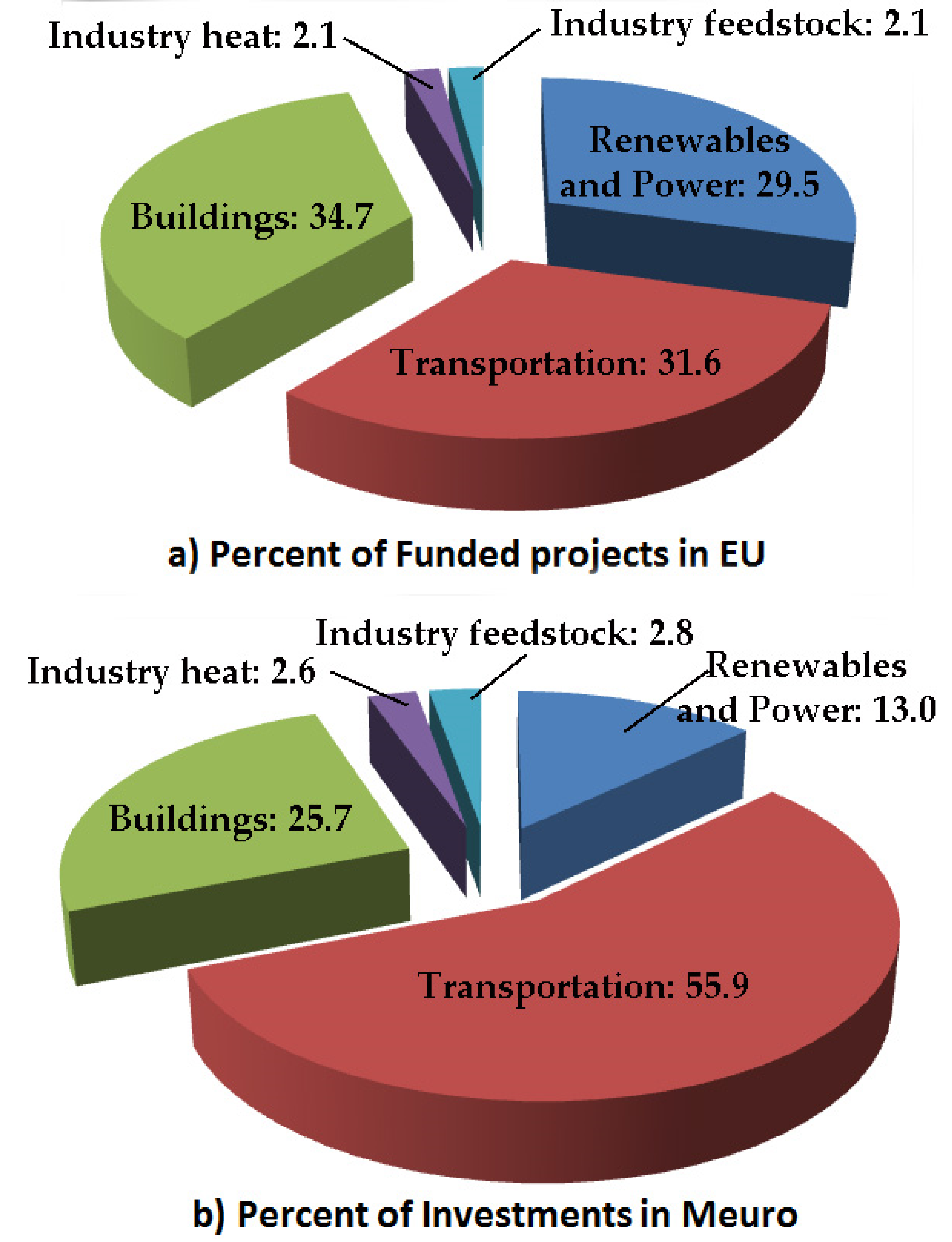
The project’s portfolio covers the renewable and power field, transportation, Buildings, industry heat, and industrial feedstock. Concerning renewable and power fields, different large-scale demonstration projects are underway. Pilot sites for power-to-gas are in operation or are being built in Spain, the Netherlands, Germany, the UK, Italy, Denmark, and the North Sea for offshore wind. France, Belgium, the Netherlands, and Germany are hosting networks of hydrogen pipelines in operation to transport excess hydrogen from one chemical plant to another chemical plant via the natural gas grid, where it is used as feedstock. Among the planned plants, there is a power-to-gas plant of 100 MW for sector coupling to be connected to the grid in Germany, whereas; in England, three salt caverns are employed to store hydrogen as of today. There are 56 projects with 215 M€ of funding.
Transportation action is focused on the possibility that hydrogen and batteries will work jointly towards more electric transport. Five passenger car models equipped with fuel cells are on the market at the moment; besides, an additional 25 models have been proposed for the next five years. Several demonstration projects, including available retrofits for vans and trucks, are in place. In Germany and Austria, projects to replace diesel with hydrogen trains are under development. A first cruise ship powered by liquid hydrogen is currently under development as well. A total of 60 projects with 926 M€ of funding exist.
In buildings, hydrogen can make a relevant contribution to decarbonizing Europe’s gas network. Hydrogen blending has started in Germany, France (hydrogen blending of up to 20% in the GRHYD demonstration project-Dunkerque), and the UK (hydrogen blending of up to 20% in the HyDeploy project at Keele University in 2019-Keele). In addition, market development for CHPs is ongoing with 66 projects and 426 M€ of funding.
Industry heat already uses hydrogen to produce heat where it is available, the effort consists of lowering the cost to be more competitive. There are four projects with 43 M€ of funding.
Industry feedstock aims to decarbonize hydrogen in existing applications such as refineries; at the moment, electrolyzers are planned or in construction with capacities ranging from 1 MW to 10 MW. In addition, clean-energy hydrogen for innovative uses is currently undergoing tests. Projects in Sweden, Finland, Austria, and Germany are verifying variations of direct reduction of iron to substitute coking coal with hydrogen, in this way, carbon-free steel could be produced. There are four projects with 46 M€ of funding.
The percent of total projects and funding are shown in
Figure 14a,b respectively.
5. Safety Considerations and Barriers
There exist several non-economic barriers to be overcome for increasing the use of hydrogen [
107,
108,
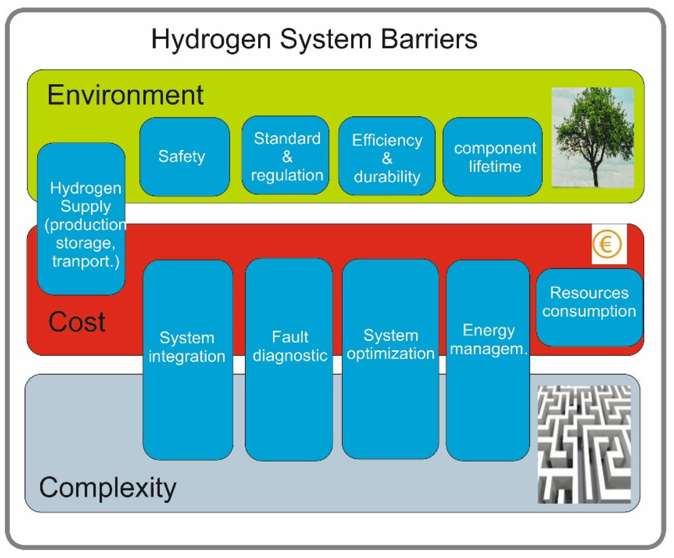
109]. Barriers concern environment, cost, and complexity; each item depends on different and common factors, as given in
Figure 15. The safe use of hydrogen is mainly tied to pressure vessel issues [
110,
111,
112]. The American Petroleum Institute (API) and the American Society of Mechanical Engineers (ASME) agreed upon the JointAPI/ASME Code for Unfired Pressure Vessels for Petroleum Liquids and Gases 1931–1934 [
113]. More recently, specific codes such as ASME, NFPA2, and SAE guarantee Standards for pressure vessels, material selection, design criteria, stress evaluation, quality control, inspection, testing, certification, and responsibilities. Composite cylinders must comply with several standards such as ISO 11119–1, ISO 11119–2, and ISO 11119–3. Besides, the ISO 11623:2015 standard gives the requirements for periodic inspection and for testing of composite transportable gas cylinders which are conceived for compressed, liquefied, or dissolved gases under pressure [
114,
115].
A common parameter used for vessels is the Maximum allowable working pressure (MAWP). Vessels could work above the MAWP for a short period such as in emergencies; however, a check before returning into service is required [
116]. Test pressure is generally set at 1.5 times the design pressure or MAWP. This test is firstly carried out at installation and then it is repeated during re-installment inspection [
116]. For hydrogen systems, one of the most essential tests for hydrogen tanks is burst pressure. In contrast, storage systems for liquid hydrogen require perfect thermal insulation to perform null boil-off systems. Standards ISO 21009–1 and ISO 21009–2 deal with design, manufacturing, inspection, tests, and operating conditions for such cryogenic pressure vessels [
117].
Among infrastructures, fueling stations have a significant impact on liquid hydrogen (LH
2) engagement in car markets concerning feasibility, economy, and safety. Hybrid hydrogen-gasoline fueling stations have been recently devised for using space more efficiently; however, they imply more complicated safety considerations. Several studies for hydrogen fueling stations with related risk assessments and analyses are proposed in [
118,
119,
120,
121,
122,
123].
A safe and compact option consists of material-based hydrogen storage; it gives a high-density storage capability. Moreover, it implies some disadvantages mainly related to high cost, initial activation, side reactions with gases, volume increase with related stresses, deterioration after several cycles, reduced quantity of recovered hydrogen, more weight as well as high capacity needed for the heat transfer system [
124,
125]. Besides, in comparison with pressure vessels, much higher GHG emissions, construction and operation costs, and resources consumption are exhibited. On the other hand, practical energy demand encourages solid-state systems [
126]. Finally, regeneration issues of chemical hydrogen storage have to be considered.
On the other hand, recent works focused on reversible hydrogen storage relying on nanocomposites have shown promising results in uptaking and releasing a high amount of hydrogen while improving the reaction kinetics. Besides, this hydrogen storage solution could meet the requirements given by the US Department of Energy (DOE) in terms of high hydrogen content, suitable thermodynamics to achieve a refueling of the tank in less than 5 min, and an operation for a large temperature range (between −40 °C and 85 °C) [
127,
128].
Safety issues are a part of barriers to be overcome to assess a path towards the substitution of conventional energy with hydrogen. Barriers consist of cost, environment, and complexity. Each barrier involves different items. As an example, the hydrogen supply affects the cost and the environment. The system integration, fault diagnosis, and management affect the cost and complexity of the system. Safety, Standards, Efficiency, and lifetime influence the environment [
7,
129].


