
Case Report

Verification Index for the Repositioning of a Single Implant Analog in the Correct Place: A Clinical Technical Case Report

by
Socratis Thomaidis
Department of Operative Dentistry, National and Kapodistrian University of Athens, 11527 Athens, Greece
Reports 2026, 9(3), 288; https://doi.org/10.3390/reports9030288
Submission received: 30 June 2026 / Revised: 23 August 2026 / Accepted: 25 August 2026 / Published: 27 August 2026
(This article belongs to the Section Dentistry/Oral Medicine)

Abstract

Background and Clinical Significance: Implant impressions can present inaccuracies, affected by many factors, such as impression technique, impression material, and parallelism or lack thereof among the implants. The use of a verification index can assess the accuracy of the mastercast and can be used in order to adjust the inaccuracy of the mastercast. This article presents a technical variation in established verification-index procedures, followed by implant analog repositioning, which can be used in case of an impression inaccuracy; Case Presentation: A patient with a moderate gag reflex received an implant. The impression of an implant and a prepared tooth was made. At the metal try-in, an inaccuracy of the mastercast was found, attributed to the final impression. A technique was illustrated, describing a polymethyl methacrylate (PMMA) verification index fabrication, followed by implant analog repositioning in the removable die of the master cast with the use of acrylic resin. This method may be used as an alternative to repeating the impression in selected clinical situations, but it is time-consuming, technique-sensitive, and needs meticulous handling; Conclusions: This is a viable technique and may represent an alternative to repeating the impression in selected clinical situations. Therefore, the clinical workflow can be reduced by one appointment. It can be helpful for patients with a moderate to severe gag reflex, since it can minimize the discomfort and stress for the patient and the dentist.

1. Introduction and Clinical Significance

Implant-supported crowns and bridges can predictably restore partially or fully edentulous ridges [1,2]. The fit of implant screw-retained partial dentures is of paramount significance for their survival, and a misfit range of up to 150 μm is considered acceptable [3,4,5,6,7,8,9]. Misfit at the implant–prosthesis interface arises from small inaccuracies occurring during impression-making [10], casting [11] and milling [12]. When an inaccuracy is identified in an implant-supported prosthesis, the use of a verification index can be made in order to assess and record it. Subsequently, the verification index can be used to adjust the inaccuracy of the mastercast.
Passive fit of the implant restoration is very important for its survival. Failure to achieve passive fit has been associated with the development of peri-implantitis and loss of peri-implant tissue at the apex of the apical ridge. It can also be associated with prosthetic complications such as loosening or fracture of the prosthetic screw, fracture of the transmucosal abutment, chipping of the veneering ceramic material, or fracture of the restoration [13,14,15,16,17,18].
Screw-retained implant-supported prostheses have the advantage of retrievability, while cement-retained multi-unit restorations can present a passive fit [19]. When the implant position and/or angulation is not favorable for screw-retained restorations, an angulated or cast abutment can be used, with a cemented restoration [20,21]. Angled screw access abutments can also be used [22]. The open tray impression technique is considered more accurate than the closed tray technique [18,23,24,25,26]. It has also been reported that a closed tray implant impression can be as accurate, or even more accurate, than an open tray impression [27,28]. The accuracy of implant impressions can be affected by the parallelism of implant placement [25,29,30,31], the depth of the implant position [32], the type of impression material used [26,33,34], the dimensional stability of the stone used to fabricate the cast [35], the die system used [36], and the length of the impression copings [37]. Some investigators reported that the single-stage double-mix technique leads to more accurate impressions compared to the two-stage technique [38,39], while others reported that the two-stage technique was more accurate [40] or that no statistically significant differences were detected among these techniques [41,42]. However, sometimes inaccuracies occur in implant impression making. Then a new impression is needed. Instead, a verification index and die repositioning techniques in dental mastercasts have been reported for fixed partial dentures, supported by teeth and/or implants [43]. The optimum verification index should be rigid, dimensionally stable, easy to construct, and not contact the soft tissues [43]. Numerous materials have been used for the fabrication of a verification index, such as poly-methyl methacrylate (PMMA) [44,45,46,47,48], PMMA sectioned and reconnected [49], PMMA in connection with metal [50], molding tray material [51], light polymerizing tray material [52], modeling compound [53], and stone grade IV [54]. A technique using multiple interlocking puzzle pieces and engaging interim abutments has been reported in order to verify the 3-dimensional spatial orientation of implant analogs on definitive casts [55]. The use of multi-unit abutment handles in conjunction with 3D-printed material has also been proposed [56]. Verification indexes are also advocated in the digital workflow of implant-supported restorations, with the use of PMMA and a 3D-printed surgical guide [57]. Verification indexes, made out of PMMA, are more practical and easier to fabricate than the ones made out of dental stone. Photopolymerizing composite resins used for verification index fabrication tend to distort [43]. Die repositioning in matercasts with removable dies, intended for fixed prosthodontics, has been performed with the use of dental stone [45], acrylic resin [44], or cyanoacrylate cement [52]. Implant analog repositioning, in solid mastercasts, has been performed with the use of dental stone [48,50].
The gag reflex is a normal defense mechanism that prevents foreign bodies from entering the trachea, pharynx, or larynx. The gag reflex is a prevalent clinical challenge in dental practice that complicates making dental impressions and may potentially lead to treatment avoidance [58,59,60].
The hard stone presectioned mastercast can present a dimensional change of 0.11% due to the setting expansion of hard dental stone [61]. When a sectioned die system mastercast is fabricated, an accuracy of 0.124% is expected, with the Pindex system presenting the highest accuracy when compared to the Belle de St. Claire system and conventional brass dowel pin system, with a dimensional change of 0.056% [61]. The Zeiser system, used for mastercast fabrication, is considered more accurate than a solid cast [62].
Metal-ceramic restorations are considered to present higher values of mechanical properties than translucent monolithic zirconia and glass ceramics [63,64,65,66,67,68,69] but demonstrate inferior translucency and esthetics [68,69].
The aim of this clinical technical case report was to illustrate clinical and laboratory procedures used in order to verify the position of an implant and reposition an inaccurate implant analog in a master cast with removable dies for a patient with a moderate gag reflex. The analog repositioning, within the removable stone die, is performed with the use of acrylic resin. This technique may represent an alternative to repeating the impression in selected clinical situations.

2. Case Presentation

A 70-year-old patient, with a free medical history and moderate gag reflex, presented at the office, complaining about mobility of the maxillary left lateral incisor (#22) as well as poor esthetics of the maxillary left canine tooth (#23). The patient suffered from generalized stage II grade I periodontal disease and was under a 6-month recall by a periodontist.
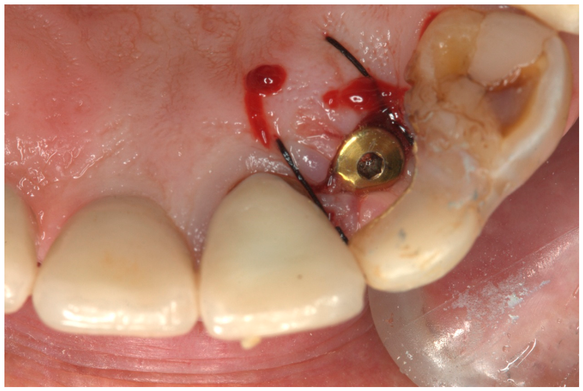
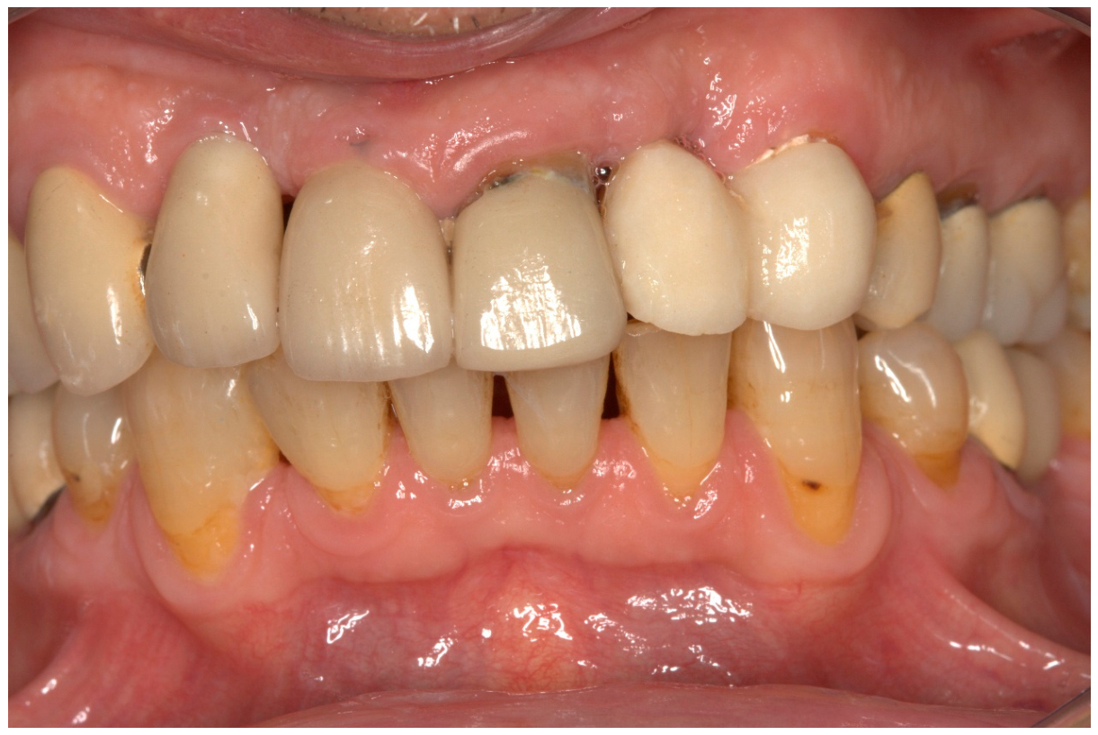
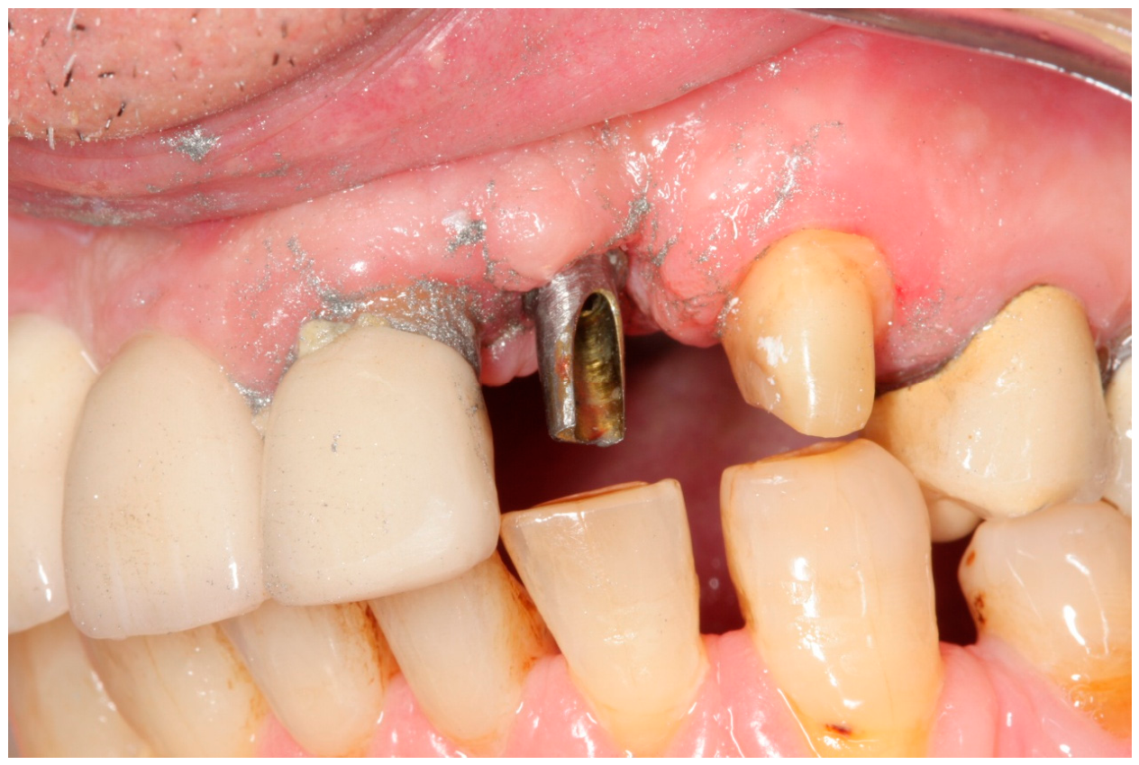
The maxillary left lateral incisor (#22) was restored with a porcelain fused to metal (PFM) crown and a post and core. Upon examination, the PFM crown on the maxillary left lateral incisor (#22) came loose with a cast post and core attached to it, and a vertical fracture was evident in the supporting root (Figure 1). The patient was informed that the tooth had to be extracted. Maxillary right central and lateral incisors (#11 and 12) were previously restored with implant-supported cemented crowns. The maxillary left central incisor (#21) was restored with a PFM crown, presenting overeruption, but the patient refused to have it replaced with a 3-unit bridge. A delayed implant insertion protocol was selected, and the extraction was performed. A composite resin build-up (Clearfil Majesty ES-2 Universal, Kuraray, Okayama, Japan) bonded (Clearfil SE Bond, Kuraray, Japan) to the canine served as an interim restoration. A CBCT (cone beam computed tomography) was made, and a narrow platform internal connection implant (3.3 mm × 10mm MIS seven) was placed (Figure 2). A preliminary alginate impression was made, which was scanned by the dental technician with a laboratory scanner (Aadva Lab Scan, GC Tech, Breckerfeld, Germany) with nominal accuracy < 10 μm. Consequently, a digital model (standard triangle language or standard tessellation language file, STL file) was created. The file from the CBCT (Dicom information) was then aligned to the digital model (STL file) with the use of BlueSky Bio Plan v5.0 software (BlueSky Bio digital) in order to design and print a surgical guide for implant placement. During the design of the implant placement position, with the use of BlueSkyBio software, it was found that the residual bone present was not enough for the placement of the implant in a prosthetically driven position. Moreover, the patient was not willing to wait for bone augmentation procedures prior to implant placement, and thus an implant was planned and positioned in a position capable of receiving a cemented restoration.
An alloplastic bone graft (EthOss, Ethoss Regeneration Ltd., Silsden, UK), comprising 65% β-TCP and 35% calcium sulfate binder, was used buccally, after implant placement, covered with the patient’s periosteum, and sutured. Therefore, no barrier membrane was used. Mucogingival surgery was not performed because the patient refused to accept this treatment plan. Moreover, the patient presented a low smile line. Therefore, the gingival recession was not apparent during smiling. The same interim restoration was used during the osseointegration period as well.
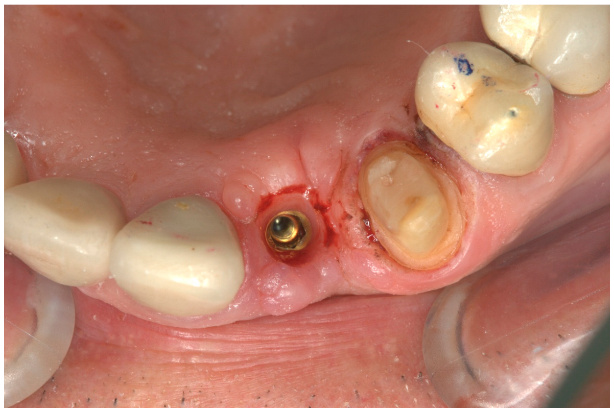
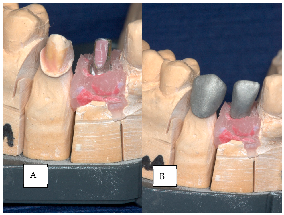
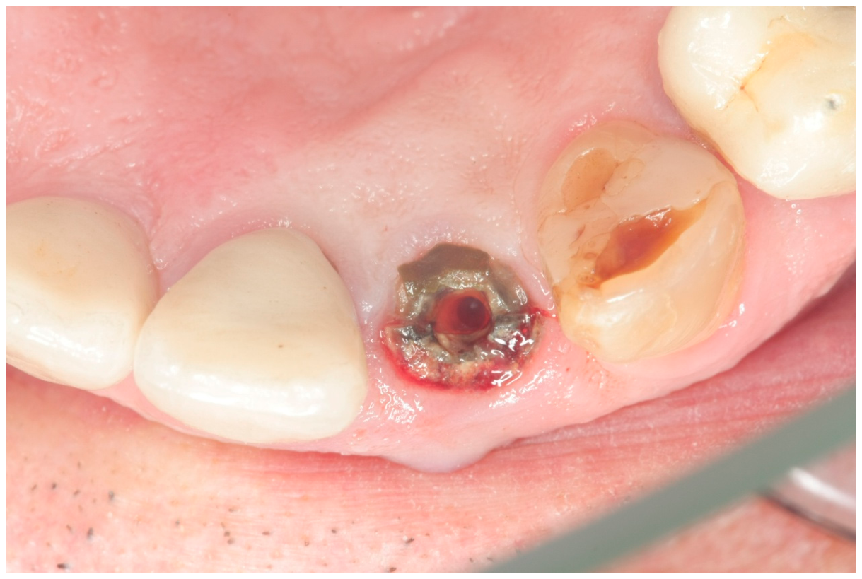
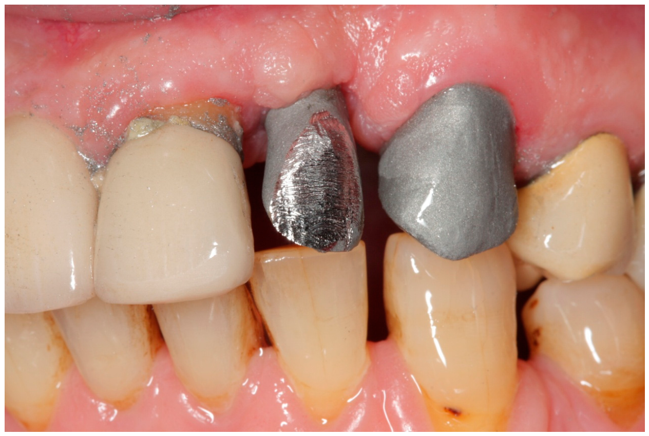
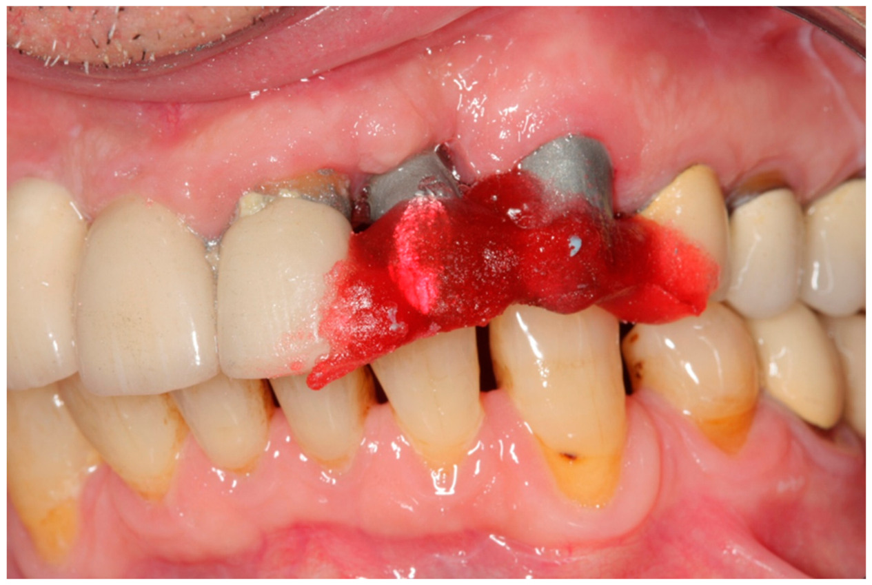
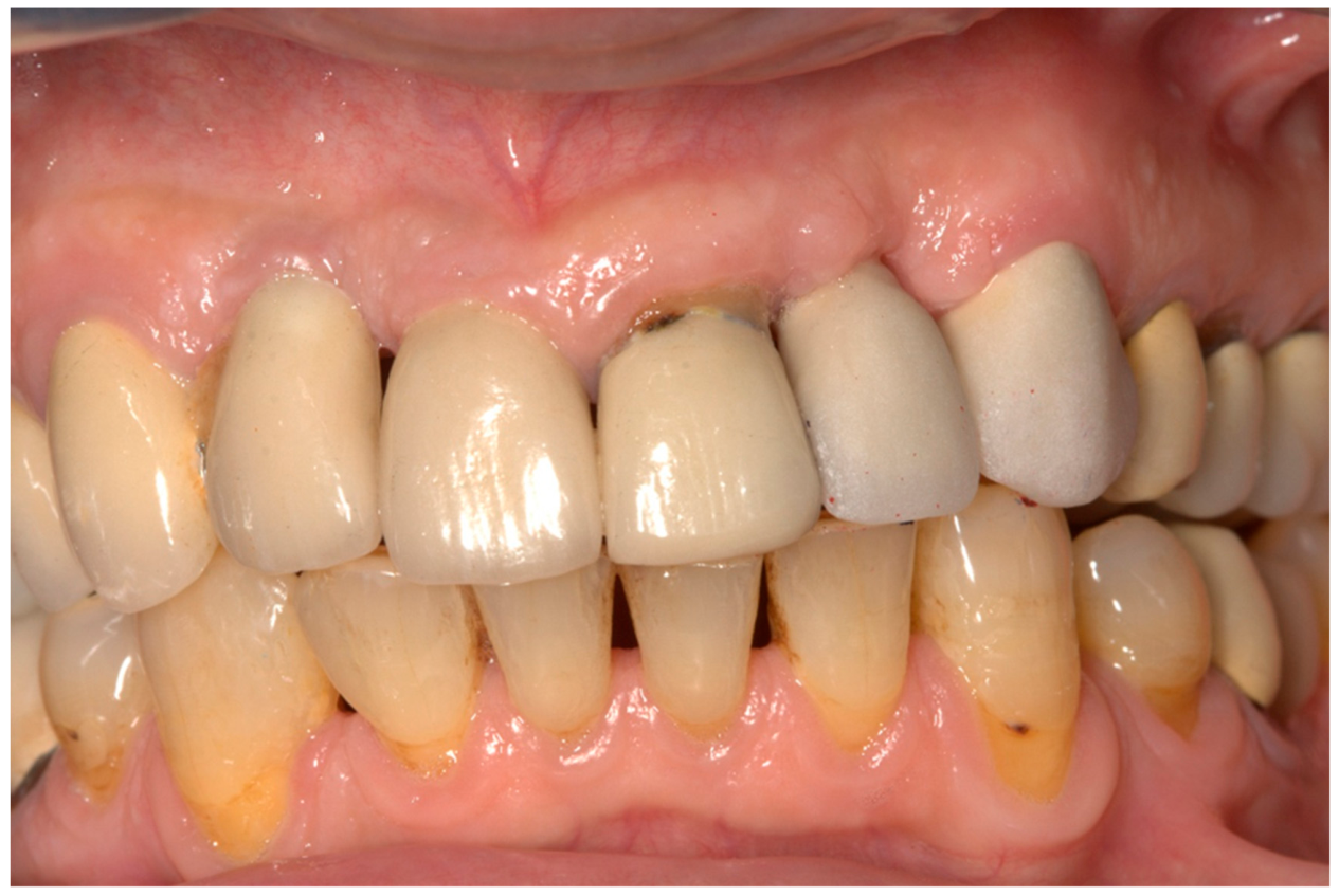
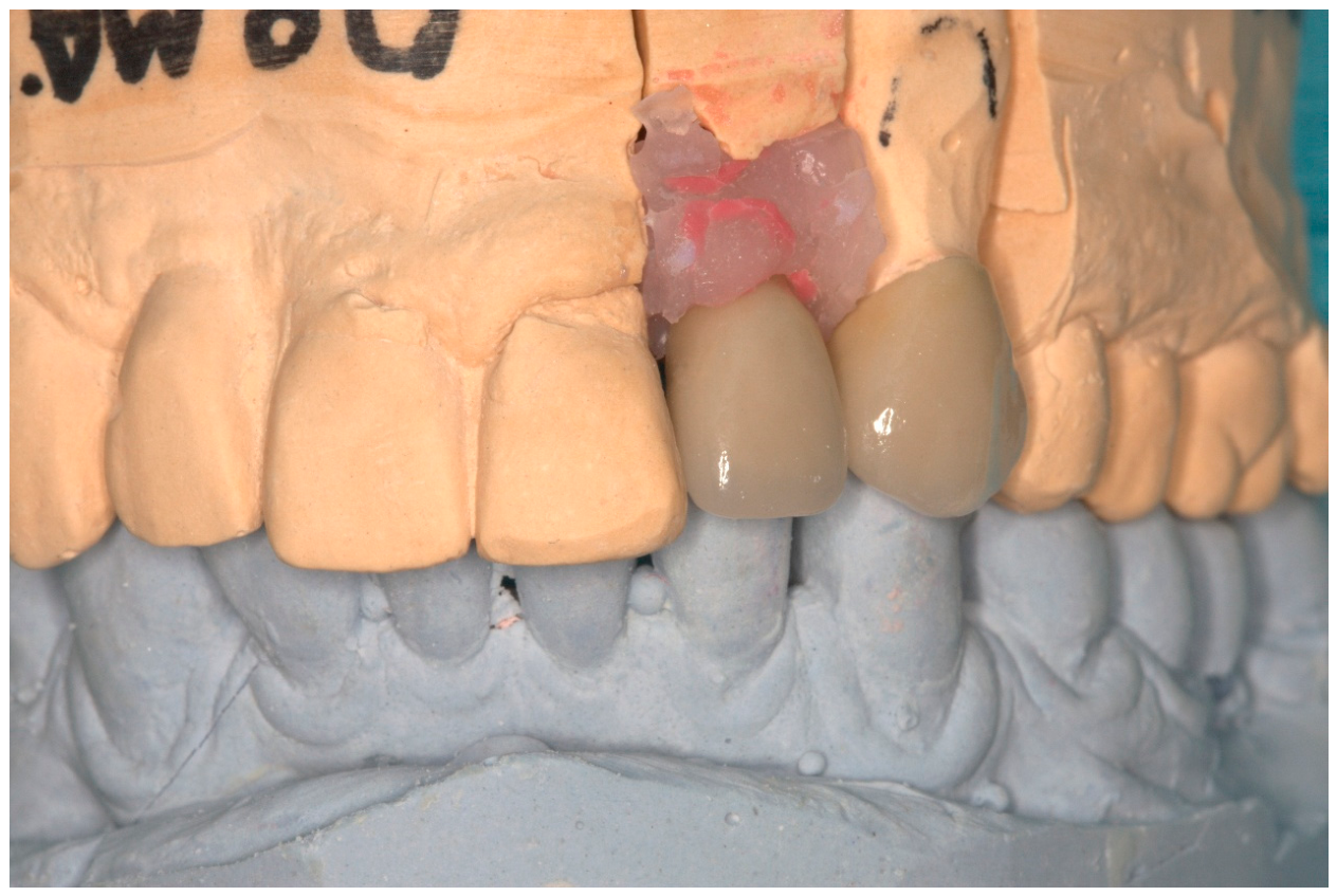
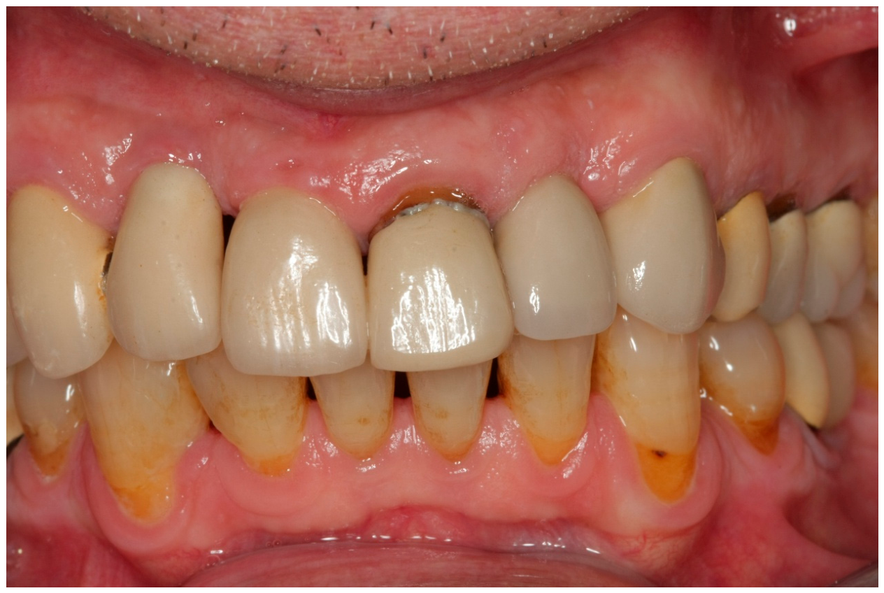
The maxillary left canine (tooth #23) was prepared for a PFM crown, and a chemically cured methyl-methacrylate (Jet tooth shade A3 powder and liquid, Lang, Wheeling, IL, USA) provisional restoration, with a cantilever for tooth # 22, was made and temporarily cemented (Figure 3 and Figure 4). Upon second-stage surgery, a healing abutment was placed, and 15 days later an open tray impression was made for the implant as well as for the prepared canine. A double retraction cord was placed around tooth #23. A perforated stock tray was used, and a double-mix heavy-body/light-body polyvinyl siloxane (Affinis Precious Light Body/Affinis Heavy Body, Coltene, Altstatten, Switzerland) impression was made and sent to the dental lab. The light-body polyvinyl siloxane was used only around the prepared tooth, while the heavy-body was injected around the impression coping. A master cast with removable dies (Zeiser system) was made by the dental technician. A 10o machined abutment for cemented restorations (MIS) was selected and prepared by the dental technician accordingly in order to present a proper path of insertion and enough space for the metal–ceramic restoration. Metal frameworks for teeth #22 and 23 were then fabricated (cast) (Figure 5). Upon the metal try-in appointment, the abutment was screwed onto the implant (Figure 6), and the metal framework did not present the same way as it did on the master cast due to impression inaccuracy (Figure 7).
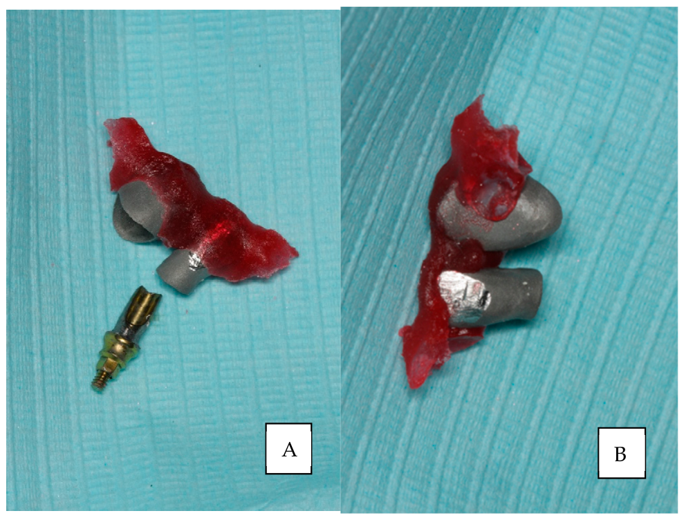
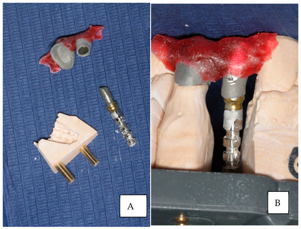
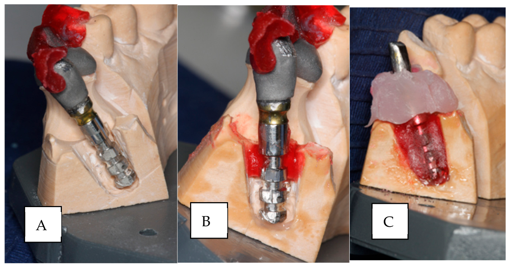
The abutment position was evaluated and was considered acceptable, offering adequate space for the crown fabrication. The space offered by the metal framework was considered enough for a metal–ceramic restoration after some minor adjustment. The extent of the inaccuracy enabled the grinding of the metal framework for the crown on #22 in order to create enough space for properly supporting the veneering porcelain (Figure 7). A depth caliper gauge was used to ensure that the metal framework thickness was not less than 0.3 mm. After verifying that the two castings were properly seated on the two abutments, a verification index was made out of a self-curing methyl methacrylate-based acrylic resin (GC Pattern Resin), which was placed around the metal frameworks and on the adjacent teeth. The castings and adjacent teeth were lubricated with a separating medium (COE Sep tinfoil substitute, GC, Alsip, IL, USA). The index was made surrounding the metal frameworks of the crowns and covering the adjacent teeth above their maximum circumference in order not to lock around them. When the acrylic index was set, it was sectioned between the castings on 22 and 23, then the two parts were connected with new acrylic and left to set for 5 min. Afterward, the fit was evaluated with the use of 3.5X magnification dental loupes (Figure 8). Upon acrylic setting, the index was removed, relieved on the interior surface of the indentations, and relined in order to minimize contraction of the acrylic (Figure 9). Provided that the fit of the acrylic index is not good enough, the procedure should be repeated. The removable die, containing the implant analog, was ground with the use of a small bur in the airotor handpiece in order to remove the implant analog (Figure 10A). Adequate space between the new position of the implant analog and the adjacent removable dies (Figure 10B), as well as with the ground die, was provided (Figure 11A). The abutment was screwed onto the implant analog. A separating solution was applied to the adjacent areas of the mastercast, as well as on the removable die around its pin, and the removable die was placed on the mastercast. Subsequently, the index was attached to the castings of #22 and 23 with sticky wax. Afterward, the machined abutment, with the attached analog, was secured on the casting of #22 with sticky wax. The whole assembly was then meticulously placed on the master cast and was seated on the die of tooth #23. At this point, it should be verified that enough space is created in the removable die in order not to contact the implant analog (Figure 11A). The space between the prepared stone die and implant analog was secured with a self-curing methyl methacrylate-based acrylic resin (Pattern Resin LS, GC, Alsip, IL, USA) and left to set (Figure 11B). Subsequently, the removable die was removed from the mastercast and filled with self-curing methyl methacrylate-based acrylic resin (Pattern Resin LS, GC, USA) (Figure 11C).
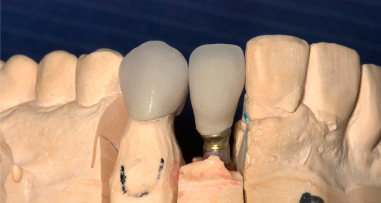
Then the mastercast was sent to the dental lab, and the oxidation of the metal framework was performed; opaque porcelain was placed and fired, and finally, body as well as enamel porcelain were built and fired (Figure 12). Thereafter, the crowns were returned for the remaining clinical procedures, i.e., porcelain bake try-in (Figure 13), glazing at the dental lab (Figure 14), and final cementation with a permanent cement (GC Fuji I self-cured glass ionomer cement, GC Corp., Tokyo, Japan) (Figure 15). Before cementation, dental Teflon was placed in the screw access hole, over the screw, to facilitate retrievability. Excess cement was then removed.

3. Discussion

The use of a verification index is proposed as a standard of care in the rehabilitation of a complete arch, maxillary or mandibular, where 4 or more implants are inserted, since an increased number of implants is more prone to lead to impression discrepancies, which can induce more destructive consequences [2,3]. It is also used when an inaccuracy is detected, in order to reposition one or more implant analogs in the mastercast [43,44,45,46,47,48,49,50,51,52,53].
The inaccuracy in the impression was probably due to the different path of insertion of the impression post from that of the direction of the impression removal or/and rotation of the impression post during screwing the implant analog. Therefore, the implant analog should be cautiously attached to the impression coping by the restorative dentist in order to prevent or eliminate the possibility of rotation of the impression coping inside the impression material. A custom tray might have prevented a possible distortion of the impression, since it is more rigid than stock trays [34]. The impression material used around the impression coping was polyvinyl siloxane heavy body, which is considered less viscous and less accurate than polyether [26,34]. In contrast, no significant differences in impression accuracy were found in a systematic review between polyvinyl siloxane and polyether [28]. The single-stage double-mix technique is considered less accurate than monophase or two-stage techniques [38,39,40,41,42]. From a prosthodontic perspective, the use of the same low-viscosity impression material to accurately record both the finish line of the prepared tooth and the implant impression coping is generally recommended to optimize detail reproduction. Consequently, the reported impression technique appears to address a problem that may have been influenced, at least in part, by the selected impression protocol.
A small magnitude of discrepancy can be realistically corrected, up to 1–1.5 mm at the most, located at the incisal edge of the restorations, in order to have the required space for veneering porcelain [70,71] and at least 0.3 mm metal thickness [71,72]. In the case of a larger inaccuracy, the metal framework of the implant-supported crown may not be used. The existing implant abutment can still be used, following some preparation by the dental technician. The use of the verification index can also be used, in conjunction with the implant abutment, in case the inaccuracy is large enough. Then, the abutment should be ground in order to create adequate space for a new metal framework and veneering porcelain. In this case, the index should wrap around the abutment, but care should be taken not to interfere with the screw access hole. The screw access hole of the abutment can be filled with Teflon in order to prevent acrylic from getting inside the hole. In the case of a large misfit, the abutment may need to be prepared by the lab; therefore, the index can be sent to the dental lab, and this procedure can be done there as well.
The volumetric polymerization contraction of Pattern resin is reported to be 5% and was found to be lower than light-cured acrylic resins [73]. In order to reduce its effect, the acrylic resin was relined by adding a minimum amount, which corresponds to a minimum amount of dimensional change due to polymerization contraction. Alternatively, the verification index could be sectioned between the dies of prepared teeth and implant casting and reconnected with a minimal amount of acrylic resin.
In the present case report, the same removable die was used and repaired with PMMA, as in the reports by Moghadam et al. [44] and Hochstedler et al. [52], but these reports described the repositioning of removable dies for tooth-supported restoration. McCartney et al. [48], on the other hand, presented a sectioned acrylic resin framework pattern, connected intraorally, and replaced the implant analog in a fixed mastercast with the use of dental stone. The accuracy of working casts made by the direct impressions and acrylic verification coping procedures demonstrates similar discrepancies, less than 100 μm [74]. Therefore, this acrylic verification coping procedure is considered equally effective in working models’ fabrication. In the present study, repairing the removable die with stone would be very difficult to execute. It might also jeopardize the retention of the implant analog, since there was very little space for dental stone. Moreover, the acrylic resin can have mechanical retention in the stone irregularities of the removable die. In the present study, a Zeiser system was used for the fabrication of the mastercast, which is considered very accurate [62].
In the present study, metal-ceramic restorations were used. The use of metal-ceramic restorations is considered a gold standard in terms of flexural strength, compared to monolithic translucent zirconia or glass ceramics [66,67]. On the other hand, monolithic translucent zirconia or glass ceramics are considered more esthetic in terms of translucency [66,67,68,69], which can mimic that of natural teeth [68]. The existing anterior teeth were restored with metal-ceramic restorations, and therefore the new crowns were made with metal ceramics as well, in order to present similar esthetics to the existing ones.
This technique may represent an alternative to repeating the impression in selected clinical situations. Thus, the use of anesthesia for repeated impressions can be avoided. This technique allows for less discomfort for the patient, and reduction in the number of following appointments, and chair time. This is important in geriatric patients or patients with a moderate to severe gag reflex. It can also be used when no other impression post of this brand and type is available at the time. It can also lead to a reduction in cost, since the existing transmucosal abutment will be used, and possibly the existing metal framework of the restoration. This is feasible when the degree of inaccuracy is minimal. The patient, suffering from a moderate gag reflex, was happy not to have the impression made again, which would be frustrating for the patient as well as the restorative dentist.
The main drawback of this technique is that it is time-consuming and technique-sensitive, needing meticulous handling. This technique would be considered inappropriate if a dentist does not feel comfortable evaluating and adjusting the thickness of the metal framework, as well as the essential space for veneering porcelain. In this case, these procedures should be performed by the dental technician. Possible sources of error can be inaccuracy of the positioning of the verification index between intraoral and laboratory manipulation. Using dental loupes when manipulating the removable die is mandatory.
The technique described is an analog technique. Currently, the digital workflow in prosthodontics is very popular and can facilitate some of the procedures used in an analog workflow. In addition, the majority of dental practitioners are not using a digital workflow, and this technique is still applicable.
Mucogingival surgery was not performed, although it would lead to better esthetics in the gingival triangle area [75].

4. Conclusions

The use of the verification index and repositioning of the implant analog in the removable die may represent an alternative to repeating the impression in selected clinical situations. This is important for patients presenting moderate to strong gag reflexes, since the described procedure is less stressful. This is a single clinical case, and further clinical validation is necessary before broad clinical recommendations can be made.

Funding

This research received no external funding.

Institutional Review Board Statement

Ethical review and approval were not required for this study, because the Dental School of National and Kapodistrian University of Athens does not ask for ethical review and approval of case reports, and the patient’s information has been de-identified.

Informed Consent Statement

Written informed consent has been obtained from the patients to publish this paper.

Data Availability Statement

The original contributions presented in this study are included in the article. Further inquiries can be directed to the corresponding author.

Conflicts of Interest

The author declares no conflicts of interest.

Abbreviations

The following abbreviations are used in this manuscript:
PFMPorcelain fused to metal
PMMAPolymethyl methacrylate
CBCTCone beam computed tomography
STLStandard triangle language or standard tessellation language

References

  1. Branemark, P.I.; Hansson, B.O.; Adell, R.; Breine, U.; Lindstrom, J.; Hallen, O.; Ohman, A. Osseointegrated implants in the treatment of the edentulous jaw. Experience from a 10-year period. Scand. J. Plast. Reconstr. Surg. Suppl. 1977, 16, 1–132. [Google Scholar] [PubMed]
  2. Jemt, T. Implant Survival in the Edentulous Jaw-30 Years of Experience. Part I: A Retro-Prospective Multivariate Regression Analysis of Overall Implant Failure in 4,585 Consecutively Treated Arches. Int. J. Prosthodont. 2018, 31, 425–435. [Google Scholar] [CrossRef] [Scilit] [PubMed]
  3. Sailer, I.; Karasan, D.; Todorovic, A.; Ligoutsikou, M.; Pjetursson, B.E. Prosthetic failures in dental implant therapy. Periodontology 2000 2022, 88, 130–144. [Google Scholar] [CrossRef] [Scilit] [PubMed] [PubMed Central]
  4. Jemt, T.; Book, K. Prosthesis misfit and marginal bone loss in edentulous implant patients. Int. J. Oral Maxillofac. Implant. 1996, 11, 620–625. [Google Scholar] [PubMed]
  5. Jemt, T.; Rubenstein, J.E.; Carlsson, L.; Lang, B.R. Measuring fit at the implant prosthodontic interface. J. Prosthet. Dent. 1996, 75, 314–325. [Google Scholar] [CrossRef] [Scilit]
  6. Jemt, T. In vivo measurements of precision of fit involving implant-supported prostheses in the edentulous jaw. Int. J. Oral Maxillofac. Implant. 1996, 11, 151–158. [Google Scholar] [PubMed]
  7. Jemt, T.; Lie, A. Accuracy of implant-supported prostheses in the edentulous jaw: Analysis of precision of fit between cast gold-alloy frameworks and master casts by means of a three-dimensional photogrammetric technique. Clin. Oral Implant. Res. 1995, 6, 172–180. [Google Scholar] [CrossRef] [Scilit] [PubMed]
  8. Jokstad, A.; Shokati, B. New 3D technologies applied to assess the long-term clinical effects of misfit of the full jaw fixed prosthesis on dental implants. Clin. Oral Implant. Res. 2015, 26, 1129–1134. [Google Scholar] [CrossRef] [Scilit] [PubMed]
  9. Al-Meraikhi, H.; Yilmaz, B.; McGlumphy, E.; Brantley, W.; Johnston, W.M. In vitro fit of CAD-CAM complete arch screw-retained titanium and zirconia implant prostheses fabricated on 4 implants. J. Prosthet. Dent. 2018, 119, 409–416. [Google Scholar] [CrossRef] [Scilit] [PubMed]
  10. Saini, H.S.; Jain, S.; Kumar, S.; Aggarwal, R.; Choudhary, S.; Reddy, N.K. Evaluating the Effect of Different Impression Techniques and Splinting Methods on the Dimensional Accuracy of Multiple Implant Impressions: An in vitro Study. J. Contemp. Dent. Pract. 2018, 19, 1005–1012. [Google Scholar] [CrossRef] [Scilit] [PubMed]
  11. Kim, S.; Nicholls, J.I.; Han, C.H.; Lee, K.W. Displacement of implant components from impressions to definitive casts. Int. J. Oral Maxillofac. Implant. 2006, 21, 747–755. [Google Scholar] [PubMed]
  12. Nedelcu, R.; Olsson, P.; Thulin, M.; Nyström, I.; Thor, A. In vivo trueness of full-arch implant-supported CAD/CAM restorations and models based on conventional impressions. J. Dent. 2022, 123, 104381. [Google Scholar] [CrossRef] [Scilit] [PubMed]
  13. Sailer, I.; Strasding, M.; Valente, N.A.; Zwahlen, M.; Liu, S.; Pjetursson, B.E. A systematic review of the survival and complication rates of zirconia-ceramic and metal-ceramic multiple-unit fixed dental prostheses. Clin. Oral Implant. Res. 2018, 29, 184–198. [Google Scholar] [CrossRef] [Scilit] [PubMed]
  14. Pjetursson, B.E.; Valente, N.A.; Strasding, M.; Zwahlen, M.; Liu, S.; Sailer, I. A systematic review of the survival and complication rates of zirconia-ceramic and metal-ceramic single crowns. Clin Oral Implants Res 2018, 29, 199–214. [Google Scholar] [CrossRef] [Scilit] [PubMed]
  15. Jung, R.E.; Pjetursson, B.E.; Glauser, R.; Zembic, A.; Zwahlen, M.; Lang, N.P. A systematic review of the 5-year survival and complication rates of implant-supported single crowns. Clin. Oral Implant. Res. 2008, 19, 119–130. [Google Scholar] [CrossRef] [Scilit] [PubMed]
  16. Pjetursson, B.E.; Tan, K.; Lang, N.P.; Brägger, U.; Egger, M.; Zwahlen, M. A systematic review of the survival and complication rates of fixed partial dentures (FPDs) after an observation period of at least 5 years. Clin. Oral Implant. Res. 2004, 15, 625–642. [Google Scholar] [CrossRef] [Scilit] [PubMed]
  17. Pjetursson, B.E.; Zarauz, C.; Strasding, M.; Sailer, I.; Zwahlen, M.; Zembic, A. A systematic review of the influence of the implant-abutment connection on the clinical outcomes of ceramic and metal implant abutments supporting fixed implant reconstructions. Clin. Oral Implant. Res. 2018, 29, 160–183. [Google Scholar] [CrossRef] [Scilit] [PubMed]
  18. Kihara, H.; Hatakeyama, W.; Kondo, H.; Yamamori, T.; Baba, K. Current complications and issues of implant superstructure. J. Oral Sci. 2022, 64, 257–262. [Google Scholar] [CrossRef] [Scilit] [PubMed]
  19. Hamed, M.T.; Abdullah Mously, H.; Khalid Alamoudi, S.; Hossam Hashem, A.B.; Hussein Naguib, G. A Systematic Review of Screw versus Cement-Retained Fixed Implant Supported Reconstructions. Clin. Cosmet. Investig. Dent. 2020, 12, 9–16. [Google Scholar] [CrossRef] [Scilit] [PubMed] [PubMed Central]
  20. Cai, Z.Z.; Lv, X.L.; Gu, Y.X.; Shi, J.Y.; Lai, H.C. Angulated Screw-Retained Versus Cemented Crowns Following Type 1C Treatment in Aesthetic Zone: A 5-Year Cohort Study. Clin. Implant. Dent. Relat. Res. 2025, 27, e70094. [Google Scholar] [CrossRef] [Scilit] [PubMed]
  21. Omori, Y.; Lang, N.P.; Botticelli, D.; Papageorgiou, S.N.; Baba, S. Biological and mechanical complications of angulated abutments connected to fixed dental prostheses: A systematic review with meta-analysis. J. Oral Rehabil. 2020, 47, 101–111. [Google Scholar] [CrossRef] [Scilit] [PubMed]
  22. Swamidass, R.S.; Kan, J.Y.K.; Kattadiyil, M.T.; Goodacre, C.J.; Lozada, J. Abutment screw torque changes with straight and angled screw-access channels. J. Prosthet. Dent. 2021, 125, 675–681. [Google Scholar] [CrossRef] [Scilit] [PubMed]
  23. Carr, A.B. Comparison of impression techniques for a five-implant mandibular model. Int. J. Oral Maxillofac. Implant. 1991, 6, 448–455. [Google Scholar] [PubMed]
  24. Wee, A.G.; Aquilino, S.A.; Schneider, R.L. Strategies to achieve fit in implant prosthodontics: A review of the literature. Int. J. Prosthodont. 1999, 12, 167–178. [Google Scholar] [PubMed]
  25. Kim, J.H.; Kim, K.R.; Kim, S. Critical appraisal of implant impression accuracies: A systematic review. J. Prosthet. Dent. 2015, 114, 185–192.e1. [Google Scholar] [CrossRef] [Scilit] [PubMed]
  26. Fathi, A.; Rismanchian, M.; Yazdekhasti, A.; Salamati, M. Accuracy of tooth-implant impressions: Comparison of five different techniques. Clin. Exp. Dent. Res. 2023, 9, 526–534. [Google Scholar] [CrossRef] [Scilit] [PubMed] [PubMed Central]
  27. Humphries, R.M.; Yaman, P.; Bloem, T.J. The accuracy of implant master casts constructed from transfer impressions. Int. J. Oral Maxillofac. Implant. 1990, 5, 331–336. [Google Scholar] [PubMed]
  28. Papaspyridakos, P.; Chen, C.J.; Gallucci, G.O.; Doukoudakis, A.; Weber, H.P.; Chronopoulos, V. Accuracy of implant impressions for partially and completely edentulous patients: A systematic review. Int. J. Oral Maxillofac. Implant. 2014, 29, 836–845. [Google Scholar] [CrossRef] [Scilit] [PubMed]
  29. Akalin, Z.F.; Ozkan, Y.K.; Ekerim, A. Effects of implant angulation, impression material, and variation in arch curvature width on implant transfer model accuracy. Int. J. Oral Maxillofac. Implant. 2013, 28, 149–157. [Google Scholar] [CrossRef] [Scilit] [PubMed]
  30. Assuncao, W.G.; Filho, H.G.; Zaniquelli, O. Evaluation of transfer impressions for osseointegrated implants at various angulations. Implant. Dent. 2004, 13, 358–366. [Google Scholar] [CrossRef] [Scilit] [PubMed]
  31. Conrad, H.J.; Pesun, I.J.; DeLong, R.; Hodges, J.S. Accuracy of two impression techniques with angulated implants. J. Prosthet. Dent. 2007, 97, 349–356. [Google Scholar] [CrossRef] [Scilit] [PubMed]
  32. Lee, H.; Ercoli, C.; Funkenbusch, P.D.; Feng, C. Effect of subgingival depth of implant placement on the dimensional accuracy of the implant impression: An in vitro study. J. Prosthet. Dent. 2008, 99, 107–113. [Google Scholar] [CrossRef] [Scilit] [PubMed]
  33. Holst, S.; Blatz, M.B.; Bergler, M.; Goellner, M.; Wichmann, M. Influence of impression material and time on the 3-dimensional accuracy of implant impressions. Quintessence Int. 2007, 38, 67–73. [Google Scholar] [PubMed]
  34. Gupta, S.; Narayan, A.I.; Balakrishnan, D. In Vitro Comparative Evaluation of Different Types of Impression Trays and Impression Materials on the Accuracy of Open Tray Implant Impressions: A Pilot Study. Int. J. Dent. 2017, 2017, 6306530. [Google Scholar] [CrossRef] [Scilit] [PubMed] [PubMed Central]
  35. Wee, A.G.; Schneider, R.L.; Aquilino, S.A.; Huff, T.L.; Lindquist, T.J.; Williamson, D.L. Evaluation of the Accuracy of Solid Implant Casts. J. Prosthodont. 1998, 7, 161–169. [Google Scholar] [CrossRef] [Scilit]
  36. Wee, A.G.; Cheng, A.C.; Eskridge, R.N. Accuracy of 3 conceptually different die systems used for implant casts. J. Prosthet. Dent. 2002, 87, 23–29. [Google Scholar] [CrossRef] [Scilit] [PubMed]
  37. Jo, S.H.; Kim, K.I.; Seo, J.M.; Song, K.Y.; Park, J.M.; Ahn, S.G. Effect of impression coping and implant angulation on the accuracy of implant impressions: An in vitro study. J. Adv. Prosthodont. 2010, 2, 128–133. [Google Scholar] [CrossRef] [Scilit] [PubMed] [PubMed Central]
  38. Kumari, N.; Nandeeshwar, D.B. The dimensional accuracy of polyvinyl siloxane impression materials using two different impression techniques: An in vitro study. J. Indian Prosthodont. Soc. 2015, 15, 211–217. [Google Scholar] [CrossRef] [Scilit] [PubMed] [PubMed Central]
  39. Mahagaonkar, P.A.; Angadi, P.B.; Naik, N.R.; Kakatkar, V.; Manjunath, S.H.; Sonawane, Y.S. Evaluation of Dimensional Accuracy of Three Combinations of Polyvinyl Siloxane Impression Material: An In Vitro Study. J. Contemp. Dent. Pract. 2020, 21, 190–196. [Google Scholar] [CrossRef] [Scilit] [PubMed]
  40. Zappi, A.; Papazoglou, E.; Anagnostou, M. Is a Wiggling-Motion Modified Two-Step Impression Technique as Accurate as Conventional Techniques in Restorative Dentistry? Dent. J. 2023, 11, 139. [Google Scholar] [CrossRef] [Scilit] [PubMed] [PubMed Central]
  41. Silva, S.C.; Messias, A.M.; Abi-Rached, F.O.; de Souza, R.F.; Reis, J.M. Accuracy of Gypsum Casts after Different ImpressionTechniques and Double Pouring. PLoS ONE 2016, 11, e0164825. [Google Scholar] [CrossRef] [Scilit] [PubMed] [PubMed Central]
  42. Pastoret, M.H.; Krastl, G.; Bühler, J.; Weiger, R.; Zitzmann, N.U. Accuracy of a separating foil impression using a novel polyolefin foil compared to a custom tray and a stock tray technique. J. Adv. Prosthodont. 2017, 9, 287–293. [Google Scholar] [CrossRef] [Scilit] [PubMed] [PubMed Central]
  43. Wong, A.W.H.; Nedelcu, R.; Hamilton, A. Clinical Recommendations for Implant Verification Jigs in Analogue and Digital Workflows. A Narrative Review. Aust. Dent. J. 2025, 70, S35–S49. [Google Scholar] [CrossRef] [Scilit] [PubMed] [PubMed Central]
  44. Moghadam, B.K.; Drennon, D.G.; Thayer, K.E. A die transfer technique. J. Prosthet. Dent. 1977, 37, 226–230. [Google Scholar] [CrossRef] [Scilit] [PubMed]
  45. Koka, S.; Linebaugh, M.L. A technique to reposition dies on the working model during fixed prosthodontic procedures. J. Prosthet. Dent. 1993, 69, 537–538. [Google Scholar] [CrossRef] [Scilit] [PubMed]
  46. Imam, A.Y.; Al-Dabbagh, R.A. Angled Abutment Transfer Jig: A Technical Report. J. Contemp. Dent. Pract. 2020, 21, 593–596. [Google Scholar] [CrossRef] [Scilit] [PubMed]
  47. Figueras-Alvarez, O.; Real-Voltas, F. Verification of the definitive cast during fabrication of implant-supported restorations. J. Prosthet. Dent. 2021, 125, 714–715. [Google Scholar] [CrossRef] [Scilit] [PubMed]
  48. McCartney, J.W.; Pearson, R. Segmental framework matrix: Master cast verification, corrected cast guide, and analog transfer template for implant-supported prostheses. J. Prosthet. Dent. 1994, 71, 197–200. [Google Scholar] [CrossRef] [Scilit] [PubMed]
  49. Knudson, R.C.; Williams, E.O.; Kemple, K.P. Implant transfer coping verification jig. J. Prosthet. Dent. 1989, 61, 601–602. [Google Scholar] [CrossRef] [Scilit] [PubMed]
  50. Jacobson, Z.; Peterson, T.; Kim, W.D. Positioning jig for implant abutments: Procedures and clinical applications. J. Prosthet. Dent. 1996, 75, 435–439. [Google Scholar] [CrossRef] [Scilit] [PubMed]
  51. Al-Abbas, H.; Al-Ajmi, M.; Pipko, D.J. A positioning jig to verify the accuracy of implant abutments. J. Prosthet. Dent. 2002, 87, 115–116. [Google Scholar] [CrossRef] [Scilit] [PubMed]
  52. Hochstedler, J.L.; Elliott, R.B. A method to position replacement dies accurately on a fixed partial denture master working cast. J. Prosthet. Dent. 1995, 74, 198–201. [Google Scholar] [CrossRef] [Scilit] [PubMed]
  53. Blasi, A.; Henarejos-Domingo, V.; Madeira, S.; Blasi, G.; Roig, M. Stone verification device for verifying the definitive cast of an implant-supported restoration: A dental technique. J. Prosthet. Dent. 2022, 128, 858–863. [Google Scholar] [CrossRef] [Scilit] [PubMed]
  54. Sadid-Zadeh, R.; O’Neal, S.J.; Liu, P.R.; Aponte-Wesson, R. A technique for verifying implant analog positions in the definitive cast. J. Prosthet. Dent. 2013, 109, 192–197. [Google Scholar] [CrossRef] [Scilit] [PubMed]
  55. Altoman, M.; Alqarni, H.; Alfaifi, M.; Kattadiyil, M.T. Digital Fabrication of a Repositioning Jig for Multiunit Abutments Placement: A Dental Technique. Int. J. Prosthod Restor. Dent. 2021, 11, 54–57. [Google Scholar] [CrossRef] [Scilit]
  56. Su, F.Y.; Tsai, J.C.; Morton, D.; Lin, W.S. Use of intraoral scan for implant-supported dental prosthesis to design and fabricate a CAD-CAM verification device: A dental technique. J. Prosthet. Dent. 2021, 125, 204–207. [Google Scholar] [CrossRef] [Scilit] [PubMed]
  57. Suh, S.; Park, S.; Kim, H.; Park, C. A Practical Approach to Full-Arch Implant Prosthesis Fabrication Using a 3D-Printed Surgical Guide Index. Int. J. Prosthodont. 2025, 38, 530–534. [Google Scholar] [CrossRef] [Scilit] [PubMed]
  58. van Houtem, C.M.; van Wijk, A.J.; Boomsma, D.I.; Ligthart, L.; Visscher, C.M.; de Jongh, A. Self-reported gagging in dentistry: Prevalence, psycho-social correlates and oral health. J. Oral Rehabil. 2015, 42, 487–494. [Google Scholar] [CrossRef] [Scilit]
  59. Saita, N.; Fukuda, K.; Koukita, Y.; Ichinohe, T.; Yamashita, S. Relationship between gagging severity and its management in dentistry. J. Oral Rehabil. 2013, 40, 106–111. [Google Scholar] [CrossRef] [Scilit]
  60. Gan, Y.; Huang, J.; Li, D.; Xu, H.; Han, S.; Zhu, H.; Wei, Z.; Cai, Z. Gag reflex management in dental practice: A bibliometric analysis from 2000 to 2025. Front. Oral Health 2025, 6, 1666164. [Google Scholar] [CrossRef] [Scilit] [PubMed] [PubMed Central]
  61. Serrano, J.G.; Lepe, X.; Townsend, J.D.; Johnson, G.H.; Thielke, S. An accuracy evaluation of four removable die systems. J. Prosthet. Dent. 1998, 80, 575–586. [Google Scholar] [CrossRef] [Scilit] [PubMed]
  62. Hsu, C.C.; Millstein, P.L.; Stein, R.S. A comparative analysis of the accuracy of implant transfer techniques. J. Prosthet. Dent. 1993, 69, 588–593. [Google Scholar] [CrossRef] [Scilit] [PubMed]
  63. Pjetursson, B.E.; Fehmer, V.; Sailer, I. EAO Position Paper: Material Selection for Implant-Supported Restorations. Int. J. Prosthodont. 2022, 35, 7–16. [Google Scholar] [CrossRef] [Scilit] [PubMed]
  64. Abduo, J.; Yin, L. Fits of Implant Zirconia Custom Abutments and Frameworks: A Systematic Review and Meta-Analyses. Int. J. Oral Maxillofac. Implant. 2019, 34, 99–114. [Google Scholar] [CrossRef] [Scilit] [PubMed]
  65. Bidra, A.S.; Rungruanganunt, P. Clinical outcomes of implant abutments in the anterior region: A systematic review. J. Esthet. Restor. Dent. 2013, 25, 159–176. [Google Scholar] [CrossRef] [Scilit] [PubMed]
  66. Zarone, F.; Russo, S.; Sorrentino, R. From porcelain-fused-to-metal to zirconia: Clinical and experimental considerations. Dent. Mater. 2011, 27, 83–96. [Google Scholar] [CrossRef] [Scilit] [PubMed]
  67. Reale Reyes, A.; Dennison, J.B.; Powers, J.M.; Sierraalta, M.; Yaman, P. Translucency and flexural strength of translucent zirconia ceramics. J. Prosthet. Dent. 2023, 129, 644–649. [Google Scholar] [CrossRef] [Scilit] [PubMed]
  68. Pecho, O.E.; Ghinea, R.; Ionescu, A.M.; Cardona Jde, L.; Paravina, R.D.; Pérez Mdel, M. Color and translucency of zirconia ceramics, human dentine and bovine dentine. J. Dent. 2012, 40, e34–e40. [Google Scholar] [CrossRef] [Scilit] [PubMed]
  69. Pekkan, G.; Pekkan, K.; Bayindir, B.Ç.; Özcan, M.; Karasu, B. Factors affecting the translucency of monolithic zirconia ceramics: A review from materials science perspective. Dent. Mater. J. 2020, 39, 1–8. [Google Scholar] [CrossRef] [Scilit] [PubMed]
  70. Shirakura, A.; Lee, H.; Geminiani, A.; Ercoli, C.; Feng, C. The influence of veneering porcelain thickness of all-ceramic and metal ceramic crowns on failure resistance after cyclic loading. J. Prosthet. Dent. 2009, 101, 119–127. [Google Scholar] [CrossRef] [Scilit] [PubMed]
  71. Aslam, A.; Khan, D.A.; Hassan, S.H.; Ahmed, B. Ceramic Fracture in Metal-Ceramic Restorations: The Aetiology. Dent. Update 2017, 44, 448–450, 453–454, 456. [Google Scholar] [CrossRef] [Scilit] [PubMed]
  72. Effortless Aesthetics. GC-Dental. Technical Manual. 2023. Available online: https://www.gc.dental/sea/sites/sea.gc.dental/files/products/downloads/proceedmczr/technique%20guide/proceed-technical-manual.pdf (accessed on 20 August 2026).
  73. Gibbs, S.B.; Versluis, A.; Tantbirojn, D.; Ahuja, S. Comparison of polymerization shrinkage of pattern resins. J. Prosthet. Dent. 2014, 112, 293–298, Erratum in J. Prosthet. Dent. 2015, 114, 872. [Google Scholar] [CrossRef] [Scilit] [PubMed]
  74. Azizogli, M.A.; Catania, E.M.; Weiner, S. Comparison of the accuracy of working casts made by the direct and transfer coping procedures. J. Prosthet. Dent. 1999, 81, 392–398. [Google Scholar] [CrossRef] [Scilit] [PubMed]
  75. Aroca, S.; Di Domenico, G.L.; de Sanctis, M. Mucogingival surgery techniques: Coronally advanced flap versus tunnel approach. J. Periodontol. 2026, 97, 1714–1732. [Google Scholar] [CrossRef] [Scilit]
Figure 1. The vertically cracked tooth #22. Initial situation.
Reports 09 00288 g001
Figure 2. The implant with a healing abutment and a provisional restoration bonded to tooth # 23.
Reports 09 00288 g002
Figure 3. The provisional was placed on tooth #23, with a cantilever for #22, following the osseointegration period.
Reports 09 00288 g003
Figure 4. The implant and prepared tooth after impression making.
Reports 09 00288 g004
Figure 5. (A) The mastercast, with the abutment in place. (B) The mastercast with the metal frameworks, before metal try-in.
Reports 09 00288 g005
Figure 6. The machined abutment screwed onto the implant.
Reports 09 00288 g006
Figure 7. Metal framework try-in after adjustment.
Reports 09 00288 g007
Figure 8. The acrylic verification index with the crowns seated upon the implant abutment and prepared tooth.
Reports 09 00288 g008
Figure 9. Buccal (A) and lingual (B) views of the acrylic verification index with the metal frameworks of crowns #22 and #23.
Reports 09 00288 g009
Figure 10. (A) The die after removing the implant analog, verification index, and implant analog; (B) the implant analog, verification index, and implant analog repositioned upon the mastercast, without the removable die.
Reports 09 00288 g010
Figure 11. (A) Connecting the verification index with the crowns repositioned over the removable die placed upon the mastercast; (B,C) the connection of the implant analog to the removable die with acrylic resin.
Reports 09 00288 g011
Figure 12. The restorations at the bisque-bake stage, on the mastercast.
Reports 09 00288 g012
Figure 13. The bisque-bake try-in of restorations on teeth #22 and 23.
Reports 09 00288 g013
Figure 14. The glazed restorations on the mastercast.
Reports 09 00288 g014
Figure 15. The cemented restorations, after maturation of soft peri-implant tissues.
Reports 09 00288 g015
Disclaimer/Publisher’s Note: The statements, opinions and data contained in all publications are solely those of the individual author(s) and contributor(s) and not of MDPI and/or the editor(s). MDPI and/or the editor(s) disclaim responsibility for any injury to people or property resulting from any ideas, methods, instructions or products referred to in the content.