All articles published by MDPI are made immediately available worldwide under an open access license. No special
permission is required to reuse all or part of the article published by MDPI, including figures and tables. For
articles published under an open access Creative Common CC BY license, any part of the article may be reused without
permission provided that the original article is clearly cited. For more information, please refer to
https://www.mdpi.com/openaccess.
Feature papers represent the most advanced research with significant potential for high impact in the field. A Feature
Paper should be a substantial original Article that involves several techniques or approaches, provides an outlook for
future research directions and describes possible research applications.
Feature papers are submitted upon individual invitation or recommendation by the scientific editors and must receive
positive feedback from the reviewers.
Editor’s Choice articles are based on recommendations by the scientific editors of MDPI journals from around the world.
Editors select a small number of articles recently published in the journal that they believe will be particularly
interesting to readers, or important in the respective research area. The aim is to provide a snapshot of some of the
most exciting work published in the various research areas of the journal.
Institut Física d’Altes Energies (IFAE), The Barcelona Institute of Technology (BIST), Campus UAB, 08193 Barcelona, Spain
†
This paper is based on the talk at the 13th International Conference on New Frontiers in Physics (ICNFP 2024), Crete, Greece, 26 August–4 September 2024.
The increased particle flux expected at the HL-LHC poses a serious challenge for the ATLAS detector performance, especially in the forward region. The High-Granularity Timing Detector (HGTD), featuring novel Low-Gain Avalanche Detector silicon technology, will provide pile-up mitigation and luminosity measurement capabilities, and augment the new all-silicon Inner Tracker in the pseudo-rapidity range from 2.4 to 4.0. Two double-sided layers will provide a timing resolution better than 50 ps/track for MIPs throughout the HL-LHC running period, and provide a new timing-based handle to assign particles to the correct vertex. The LGAD technology provides suitable gain to reach the required signal-to-noise ratio, and a granularity of 1.3 × 1.3 mm2 (with 3.6 M channels in total). This paper presents the current status of the HGTD project with emphasis on the sensor development and module results.
The Large Hadron Collider will start the High Luminosity upgrade (HL-LHC) by the end of 2026. The luminosity is projected to increase by 7.5 times and reach a total integrated luminosity of 4000/fb [1]. The collisions per bunch crossing (BX) will be between 140 and 200 with 1.5 vertex/mm on average along the z-axis. This presents important challenges for the radiation hardness of the detectors as well as for the tracking performance of ATLAS.
The Inner Tracker (ITk) will be introduced to improve the tracking performance up to [2]. Its z0 resolution on the forward region though, especially for the low transverse momentum () particles, will not reach a good enough position resolution to resolve all the vertices.
The High-Granularity Timing Detector (HGTD) is being introduced to add timing information, which, combined with ITk spatial information, will allow the LHC to recover performance in the forward region where the ITk resolution is worse [3]. By enabling a better separation of overlapping events, the HGTD will lead to improved identification of signal processes (through pile-up rejection and better lepton isolation, for example), which in turn will enhance the discovery potential for new physics. Additionally, the HGTD will enable more accurate measurements of decay times and properties of short-lived particles, enriching the overall physics program of the ATLAS collaboration.
In addition, it will also provide a luminosity measurement with uncertainty per BX to further improve the experiment performance since the luminosity is a critical contribution to the overall systematic error.
As it will be detailed below, the HGTD relies on Low-Gain Avalanche Detectors (LGADs), which are silicon sensors with a thin multiplication layer that provides excellent timing resolution. The LGAD sensors are segmented into a 15 × 15 matrix with 1.3 × 1.3 mm2 pads, which are readout via solder bumps by a dedicated front-end chip (called ALTIROC). Two hybrids joined by a flex PCB define the HGTD module. In total, 8032 modules will be mounted on two disks at each side of the ATLAS interaction point covering the pseudo-rapidity region between 2.4 and 4.0. This paper presents the current status of the HGTD project, which, at this time, is about to start the pre-production stage.
2. HGTD Layout
The HGTD is composed of two end-cap disks placed between the barrel and the end-cap calorimeters. They will be placed symmetrically along the z-axis at 3.5 m from the interaction point. Each end-cap will contain two active double-sided disks, their electronics, connections and cooling required for the detector operation. The active area of each disk will cover the radius from 120 to 640 mm, with a total detector radius of 1.1 m including the peripheral electronics and other services (see Figure 1).
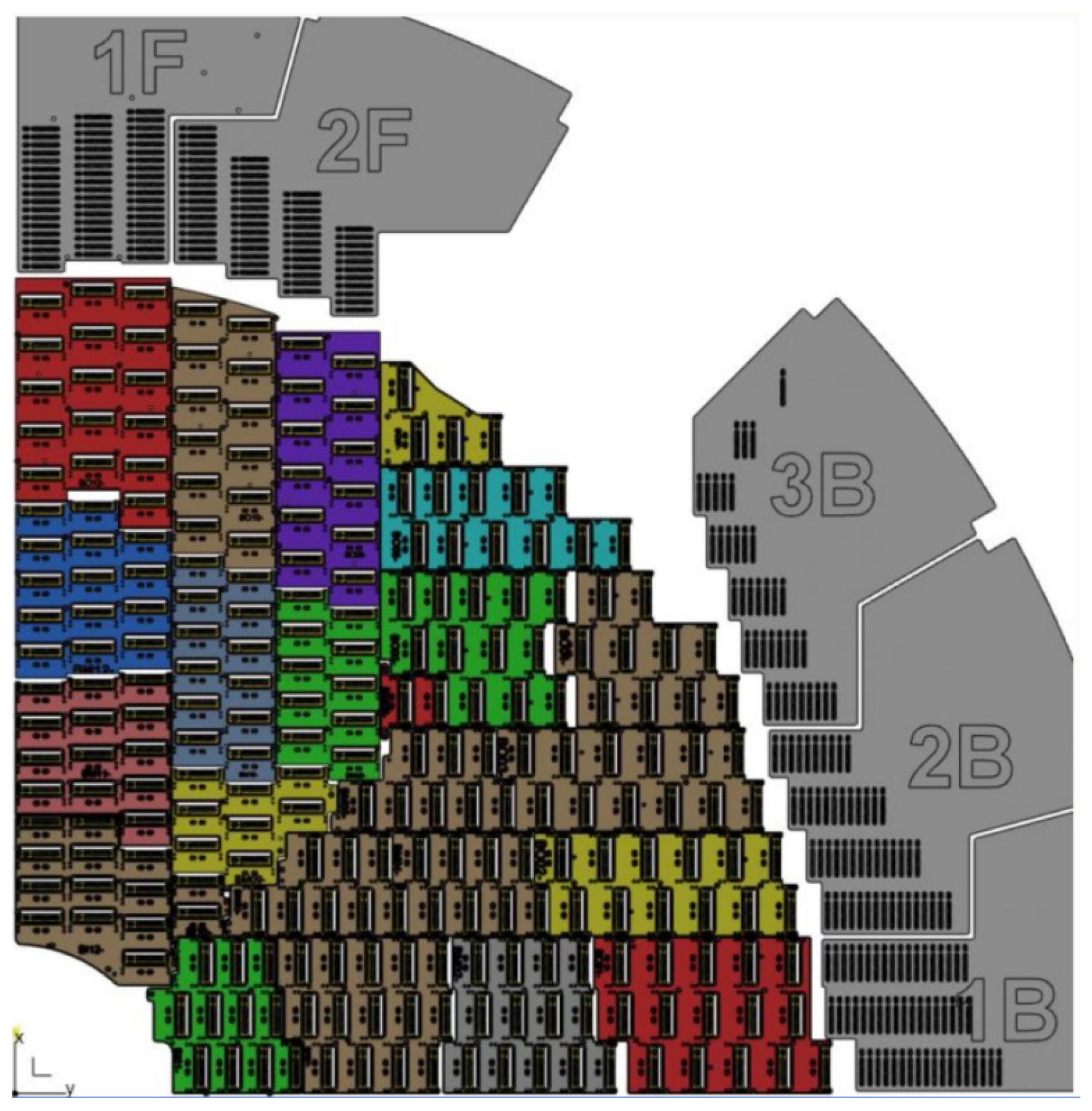
The HGTD will be comprised of 8032 modules of about mm2 with a total of more than 3.6 M channels. The modules will be organized in detector units (DUs), which will consist of different sets of modules attached to mechanical PEEK (Polyether Ether Ketone) frames that will hold them together and in contact with an aluminum cooling plate (see Figure 2). At the outermost radius, a set of Peripheral Electronics Boards (PEBs) will be placed to connect to each single module using a flex tail [4]. The same layout will be repeated for every quadrant of a double-sided disk.
The PEBs will merge and translate electrical signals through Low Power Giga Bit Transceiver (lpGBT) channels [5] from different modules to optical connections interfacing the Front-End Link eXchange (FELIX) readout system [6]. They will also provide the Low Voltage (LV) DC power to the modules using bPOL12 Point of Load DC/DC converters [7], route an independent High Voltage (HV) channel for each module and monitor the module power consumption and temperature. Figure 1 also depicts an axial view of one HGTD disk showing the three groups of modules (discussed in the next section) and the PEBs distributed at the perimeter.
3. Challenges
3.1. Time Resolution
The main contribution of the HGTD to ATLAS is to add timing information to the tracks in the forward region in order to be able to resolve the vertices not only spatially but also in time, thus reducing the detrimental effect of pile-up. During the HL-LHC phase, as is currently the case, the bunch crossing (BX) time will be 25 ns. Each BX will contain up to 200 collisions with a typical spread in time of ps, and thus the time resolution needed to discriminate their tracks is in the range of a few tens of pico-seconds. The timing resolution requirements for the HGTD are 30 ps per track at the start of the lifetime and 50 ps per track after maximum fluence while maintaining a hit reconstruction efficiency above 95%. The main contributions to the hit time resolution are summarized in the following equation:
The Landau contribution, , is caused by the non-uniform energy deposit by a charged particle along the path of a silicon sensor. It is intrinsic to the sensor and it depends on its construction and operational variables, such as bias voltage and temperature.
The Time-walk (TW) contribution, , arises from the apparent variation in the Time of Arrival (ToA) for particles hitting the sensor simultaneously but with differing signal amplitudes. This occurs when the ToA is determined using only a single discriminator threshold. In order to compensate for that effect, the Time over Threshold (ToT) is measured, correcting the ToA significantly.
The rest of the contributions are expected to be less relevant to the total time resolution. The jitter, , is caused by the noise superimposed on to the sensor signal that leads to a dispersion of the ToA. The jitter on the clock, , used by the ASIC as a reference to measure the ToAs adds up to the total time resolution. This term includes the LHC clock jitter contribution, which is known to be really small, and the contribution from the signal distribution within the HGTD, which is estimated and expected to be of the order of a few pico-seconds. Finally the Time-to-Digital Converter (TDC) bin width, , affects also the final time resolution.
The time resolution for a track improves with the amount of hits according to the following equation.
3.2. Radiation Hardness
Radiation hardness is of utmost importance for the HGTD due to it being relatively close to the interaction point and thus subjected to considerable radiation damage. All the components of the HGTD must be able to withstand the radiation levels it is expected to encounter during its operational lifetime, a maximum fluence of 1 MeV /cm2. The tracks of the particles produced by the collisions will not be evenly distributed over the active range covered by the HGTD, having most of the tracks intersecting the area with higher .
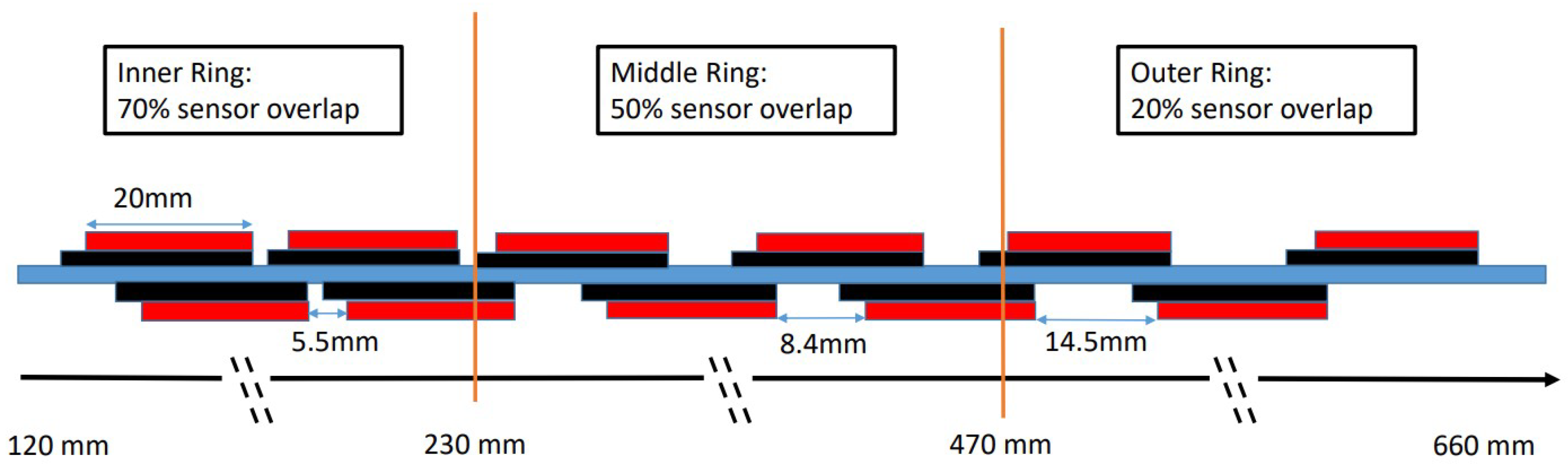
Due to the high radiation hardness requirements and non-uniformity coverage of the tracks, each detector disk is grouped into three independently replaceable rings covering three different ranges. The foreseen strategy is to replace the innermost ring three times (every 1000/fb) and the middle ring one time (every 2000/fb), while the outer ring is expected to withstand the full 4000/fb until the end of life of the detector. The three independently replaceable rings also feature different sensor overlap (see Figure 3).
This replacement strategy was chosen to limit the radiation that the components of HGTD will have to endure to a maximum fluence of 1 MeV /cm2 and a corresponding dose of 2 MGy during their lifetime. The limiting factor that requires replacing the disks is the expected degradation of the silicon sensors (LGADs) with radiation.
4. HGTD Components
4.1. Low-Gain Avalanche Detectors
The sensors used by HGTD are Low-Gain Avalanche Detectors (LGADs), providing the necessary time resolution and radiation hardness. They are designed as n-on-p silicon sensors with a p-type multiplication layer and a gain of around 20 to keep signal proportionality and reduce the noise.
The active thickness of the sensors is 50 µm to reduce the Landau contribution to the time resolution, by reducing the path that charged particles can travel through the sensor.
The sensors are carbon-enriched. Carbon is introduced in the region of the multiplication layer to reduce the acceptor removal effect that otherwise reduces significantly the gain of the multiplication layer after irradiation [8].
The HV will be limited to 550 V to keep the electric field strength below 11 V/µm in order to avoid damaging the sensor due to the collapse of the electric field induced by a single charged particle, a process called Single Event Burnout (SEB). This type of failure was observed in previous prototypes, and it has been characterized on several test beams to determine the maximum level of HV [9,10].
4.2. Front-End ASIC
The sensor readout ASIC will be the ALTIROC (ATLAS LGAD Timing Integrated Read-Out Chips), manufactured using the 130 nm CMOS node from TSMC. It will provide the ToA and ToT and column/row information for each hit on the sensor matrix, as well as a luminosity measurement counting hits in each bunch crossing [3]. The control logic and data processing are triplicated to improve the immunity to Single Event Upsets (SEUs).
The electronics jitter for an input charge of 10 fC (the expected charge for a MIP on a 50 µm thick sensor and a gain of 20) is required to be smaller than 25 ps. The contribution to the time resolution from the ASIC TDC bin width (20 ps) should be negligible, while the time-walk should be smaller than 10 ps after correction. At the end of lifetime, i.e., after irradiation of 2 MGy, the jitter should be below 70 ps also at a threshold of 10 fC.
The studies presented here are based on the ALTIROC3. It contains the full pixel readout matrix with a transimpedance amplifier per channel and the required peripheral electronics, while being radiation hard. The next version of the chip, the ALTIROCA, which includes minor improvements, has been recently produced and it is being tested.
4.3. Modules
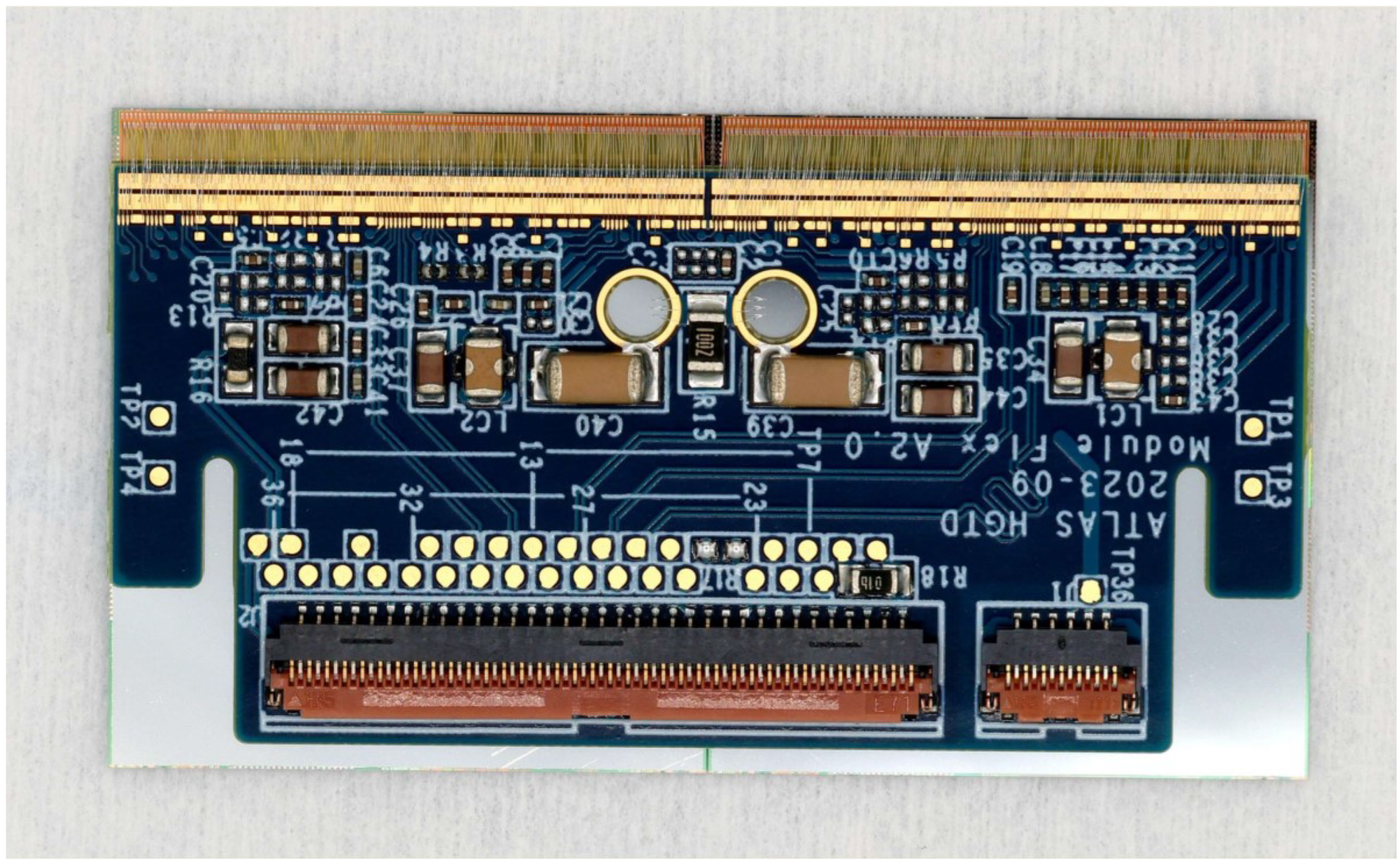
The HGTD modules consist of a flex PCB (Printed Circuit Board), which is glued on top of two sensors each containing 225 channels of mm2 distributed on a matrix. The sensors are bump bonded to their respective Front-End (FE) readout ASICs, the ALTIROC. Figure 4 shows one of the HGTD modules after the assembly.
5. Assembly
The assembly of modules and the loading of them to detector units is carried out by different research groups belonging to the ATLAS HGTD collaboration, while the final assembly and integration of the detector will be carried out at CERN.
5.1. Module Assembly
Each assembly site will receive the components to build and test the modules, these being hybrids (sensors bump bonded to the readout chips), module flex PCBs and detector unit frames.
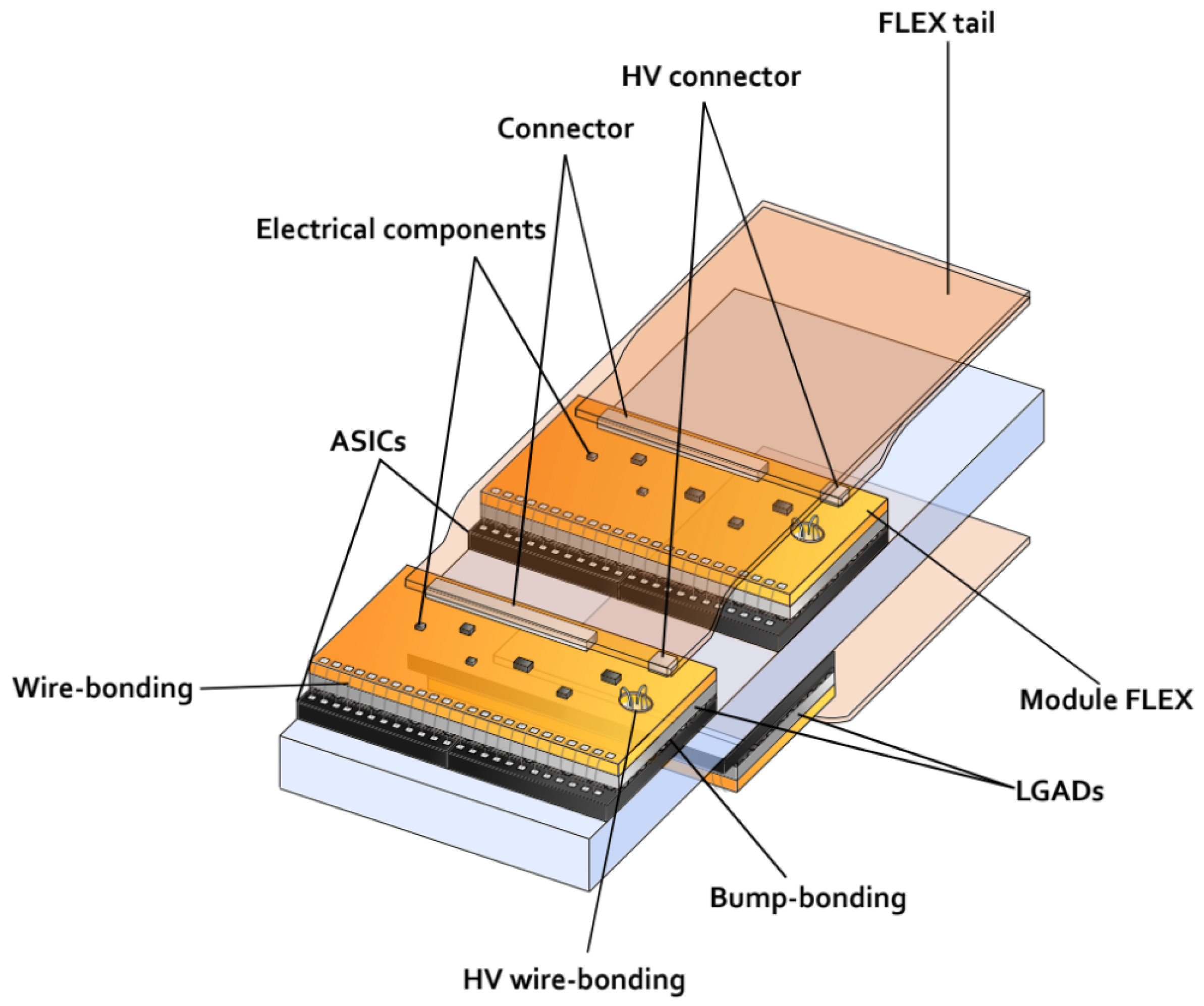
To complete the assembly process of a module, two hybrids need to be attached to a module flex PCB while maintaining a set of strict mechanical tolerances (in the order of tens of micrometers). Those tolerances ensure that the module can later be wire bonded and loaded to a support unit. There are currently two methods for performing the hybrid positioning and gluing: one uses dedicated jigs while the second one relies on a Cartesian robot. Figure 5 shows a representation of three modules in contact with the cooling plate and connected to the flex tails.
The sites using jigs place the two hybrids on an inlay that provides an X-Y and rotation reference for each (on a corner) while a plane holds them with a vacuum at a specific height. The jigs also provide a similar inlay reference on the flex PCB and hold it also with a vacuum. The glue is then deposited on to the flex with a specific pattern of dots of about 1 mm in diameter using a stencil or with a Cartesian robot with a glue dispenser. Then, using four precisely machined columns, the two inlays, one for the two hybrids and one for the flex PCB with deposited glue, are brought to a controlled distance, which determines the module thickness. The jig remains closed until the glue is cured.
Tools to enable the assembly of several modules in one jig are being developed. This will allow the speed up of the assembly process while reducing the laboratory space needed for the parallel assembly of modules.
After assembly, visual inspection and metrology will need to be performed as Quality Control (QC). If successful, the module can proceed to the wire bonding step. The wire bonding will electrically connect the ALTIROC on each hybrid to the corresponding pads on the flex PCB, and the sensors to the HV flex PCB rings by means of 25 µm thick aluminum wires. Once the wire bonding is completed, the module can be characterized on a test bench.
During the prototyping phase of the project, hundreds of modules were produced. This effort culminated in November 2024 after about 50 hybrids with ALTIROC3 ASICs and pre-production LGAD sensors were produced and successfully tested, as mentioned below.
5.2. Detector Unit Assembly
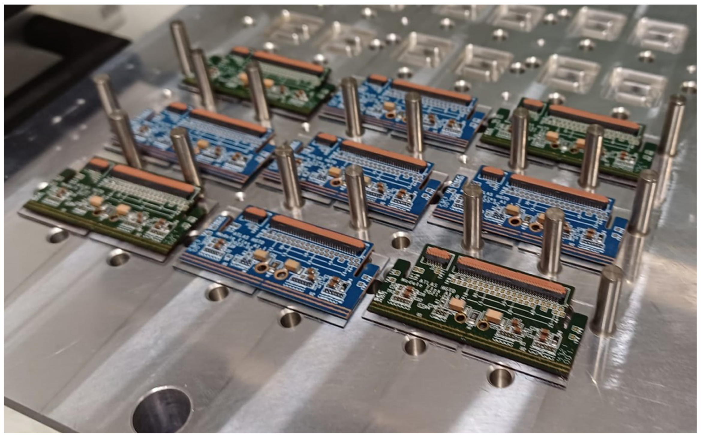
A varying amount of modules will populate the different types of detector units. To build a detector unit, the modules are placed on a vacuum plate providing X-Y positioning references for the module edges on bored holes accessible by using dowel pins. Accurately positioning the modules is critical to ensure that they can be connected to the PEBs through the flex tails.
Four glue dots are applied at the periphery of each of the flex PCBs of the modules, which are used to attach them to the detector unit PEEK frame, which is placed on top of the modules and fixed with screws (see Figure 6). Those screws press the frame to the vacuum plate with the modules in between. This ensures that all the module hybrids (on the ASIC side) are coplanar and thus are all in contact with the cooling plate in the final detector.
When the loading is finalized, the detector unit is moved to a transport plate and visual inspection and electrical tests can be performed to ensure no modules were damaged during loading. Finally, the DUs will be shipped to CERN for the assembly onto the cooling disks and integration. The cooling will be provided by a CO2 system operated at −35 °C, which will run through the tubes inside the cooling plate on which the modules are mounted.
5.3. Thermal Cycle Studies
During its lifetime, the HGTD will experience thermal cycles through normal operation of the detector. As the modules contain materials with different coefficients of thermal expansion, thermal cycles result in mechanical stress applied to the components of the system. Especially sensitive are the bump bonds between the ASIC and the LGAD sensor, since temperature variations can lead to cracking of the bumps, resulting in disconnected pixels.
To evaluate the detrimental effects of temperature changes, the modules have been first characterized with an Sr-90 beta source, then exposed to thermal cycles between −45 °C and 40 °C on a climate chamber, and then measured again. The number and locations of disconnected pixels after thermal cycles has been studied.
After initial studies to ensure the modules survive the thermal cycles, the total thickness of the sensors was increased to 775 µm (active area + substrate). With this thickness, modules were able to sustain more than 100 cycles before suffering the first bump failures. Furthermore, the ALTIROC-A chip will increase the number of bumps in the periphery to further increase robustness against thermal cycles.
6. Characterization
The characterization is performed on test benches using the ALTIROC injection mechanism and radiation sources, and, for a small number of modules, with particle beams. The test bench measurements for ALTIROC provide basic performance evaluation and QC, while the test beam characterization provides valuable time resolution and sensor efficiency results.
6.1. Test Bench
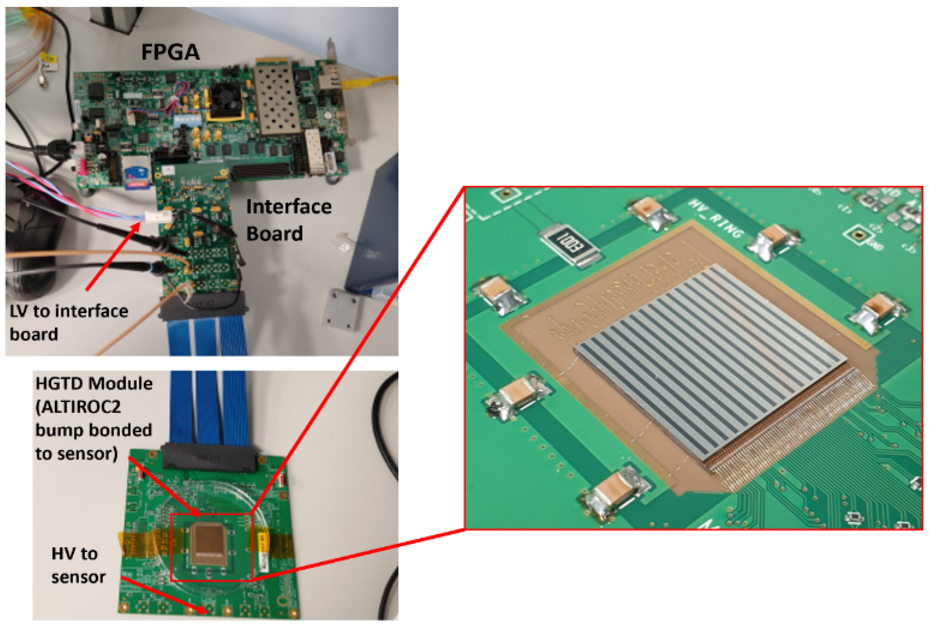
For the test bench characterization of the ALTIROC modules, two readout systems are available: FADA [11] (developed at IJCLab) and AlVin [12] (developed at IFAE). Both share common hardware, shown in Figure 7.
The readout hardware is based on a ZC706 board from Xilinx [13] which contains a Zynq FPGA connected to a PC with an RJ45 using the TCP/IP network protocol. One of the two FPGA Mezzanine Card (FMC) ports available is used to connect to a custom interface board providing a flex tail connector, which enables communication to a module. The LV power for the interface board and the ALTIROC is provided by an external power supply, while the HV for both sensors (one in each module hybrid) is provided via a BNC port on the same interface board. The test bench characterization can be used to evaluate basic module functionality as well as the sensor IV, minimum threshold, jitter, bump connectivity and ToA/ToT bin width measurements. The bump connectivity test is performed placing a radioactive source on top of the module. All pixels should detect events if they are well connected, otherwise they are considered to have had a bump failure on the pixels showing no events. The result of such a test is provided in Figure 8.
6.2. Test Beam
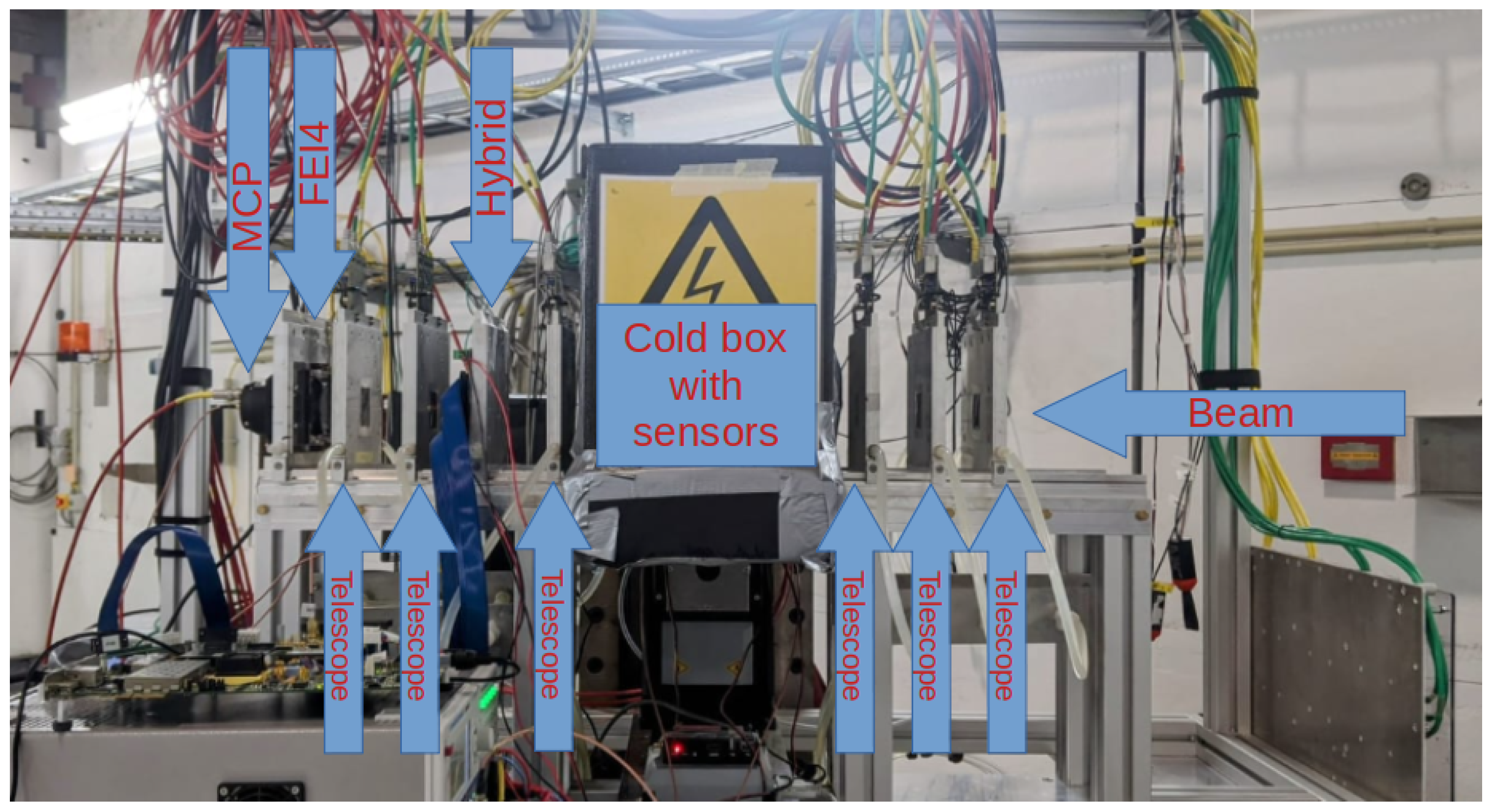
The test beam setup is critical to evaluate the performance of the modules in a realistic environment, mainly with beams of particles that are similar to MIPs. A typical setup for the most recent test beams includes a telescope to provide tracking information, an FEI4 [15] used for triggering on a specific spatial region, a Micro Channel Plate (MCP) providing outstanding time resolution and, of course, the hybrid or module as the device under test (DUT). Additionally, to measure the MCP signal, the ALTIROC TDC reference clock and some other debug signals, an oscilloscope with 1 GHz bandwidth and a sampling rate of 6.25 Gs/s is used. Figure 9 shows the detectors in the measurement setup.
All the detectors and the oscilloscope are controlled and synchronized with the EUDAQ2 data acquisition framework [16] and a trigger logic unit (TLU) [17]. AlVin is used as the test beam DAQ system, as in the test bench setup. The main difference are two custom PCBs connected to the second FMC port on the FPGA board to interface the TLU. The AlVin EUDAQ2 producer enables the communication between AlVin and the telescope.
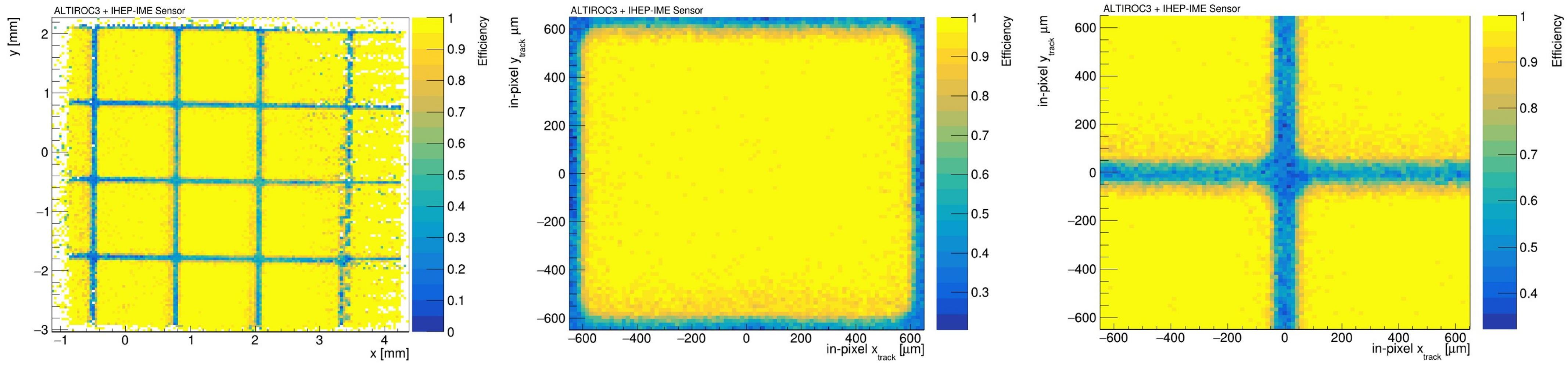
For the analysis of the test beam data, the Corryvreckan [18] framework is used. It allows for the track reconstruction and efficiency calculation and plotting, as depicted below. The efficiency is calculated for the DUT as events on a given pixel divided by the amount of reliable tracks (detected on a minimum amount of telescope planes) passing through it. Figure 10 shows that, within the central part of the sensor pixels, an efficiency of 99% is achieved, satisfying the HGTD requirements before irradiation. These results were obtained with a bias voltage of 121 V and an average ALTIROC3 threshold of around 9.6 fC with a noise level of about 0.4 fC operating at −30 °C.
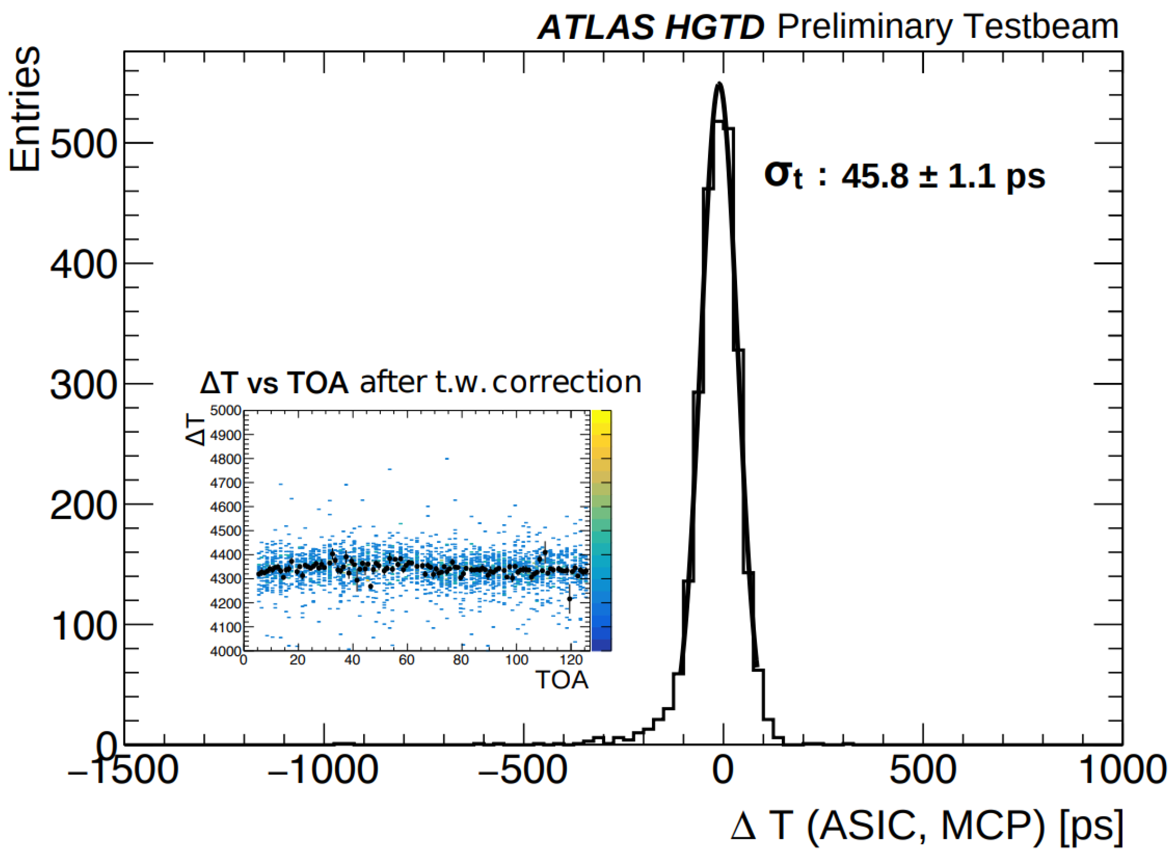
To calculate the time resolution, the difference between the ALTIROC 40 MHz TDC clock to the MCP is compared with the ToA code measured by the ASIC times the ToA bin width. After building a histogram with this time difference, a Gaussian fit provides the final time resolution from its sigma parameter. The picture below shows that a time resolution of about 46 ps is obtained for a channel in an unirradiated ALTIROC3 hybrid during a beam test.
Each track is expected to produce multiple hits on the HGTD due to the two double-sided disks per end-cap and their overlapping regions (see Figure 3). The time resolution per track will benefit from combining multiple hits, which will reduce the overall timing uncertainty according to Equation (2). Figure 11 represents the performance of a single hit, and the combination of multiple hits produced by each track is expected to be close to the 30 ps time resolution per track target.
7. Conclusions
During the HL-LHC phase, the HGTD will be integrated into the ATLAS detector to enhance pile-up rejection and enable precise luminosity measurements for each bunch crossing.
The module prototyping phase has been recently completed. The latest ALTIROC3 modules presented very good bump connectivity and were shown to be able to sustain the thermal cycling needs of the HGTD. ALTIROC3 hybrids were also tested with particle beams, delivering a time resolution of about 46 ps per hit, which leads to close to 30 ps time resolution per track, consistent with the HGTD requirements.
The effort to evaluate the performance of the final module configuration is ongoing. Recently, HGTD modules were tested in a test beam for the first time; the analysis of the gathered data on efficiency and time resolution is still ongoing.
The ALTIROC-A chip has been recently produced and the initial testing of these devices is also underway.
Funding
This work was partially funded by grant PID2021-124660OB-C21 funded by MCIN/AEI/10.13039/501100011033 and by “ERDF A way of making Europe”, by the EC (H2020 project AIDAinnova, GA no. 101004761), co-funded by the Recovery and Resilience Facility (Spain), and by the MCIN with funding from the European Union NextGenerationEU (PRTR-C17.I1) and by the Generalitat de Catalunya, AGAUR 2021-SGR-01506. IFAE is also partially funded by the CERCA program of the Generalitat de Catalunya.
Data Availability Statement
The datasets presented in this article are not readily available because the data are part of an ongoing study.
Acknowledgments
We acknowledge SPS and DESY staff for successfully operating their facilities and for continuous support to the users. Some measurements leading to these results have been performed at the Test Beam Facility at DESY Hamburg (Germany), a member of the Helmholtz Association (HGF).
Conflicts of Interest
The authors declare no conflicts of interest.
References
Apollinari, G.; Béjar Alonso, I.; Brüning, O.; Lamont, M.; Rossi, L. High-Luminosity Large Hadron Collider (HL-LHC): Preliminary Design Report; Ser. CERN Yellow Reports: Monographs; CERN: Geneva, Switzerland, 2015; Available online: https://cds.cern.ch/record/2116337 (accessed on 25 March 2025).
The LHC Experiments Committee. Technical Design Report for the ATLAS Inner Tracker Pixel Detector; Technical Report; CERN: Geneva, Switzerland, 2017; Available online: https://cds.cern.ch/record/2285585 (accessed on 25 March 2025).
The LHC Experiments Committee. Technical Design Report: A High-Granularity Timing Detector for the ATLAS Phase-II Upgrade; Technical Report; CERN: Geneva, Switzerland, 2020; Available online: https://cds.cern.ch/record/2719855 (accessed on 25 March 2025).
Manzano, M.R.; Weitzel, Q.; Brogna, A.; Ehrecke, J.; Kurt, A.; Masetti, L.; Patel, J.; Pham, B.; Theobald, P. Design and testing of long Flexible Printed Circuits for the ATLAS High Granularity Timing Detector demonstrator. J. Instrum.2023, 18, C02015. [Google Scholar] [CrossRef]
Montesinos, D.H.; Baron, S.; Biereigel, S.; Hazell, P.; Kulis, S.; Leitao, P.V.; Moreira, P.; Porret, D.; Wyllie, K. Overview of the production and qualification tests of the lpGBT. J. Instrum.2024, 19, C04048. [Google Scholar] [CrossRef]
Ilic, N.; Vermeulen, J.; Kolos, S. FELIX: The new detector interface for the ATLAS experiment. EPJ Web Conf.2019, 214, 201921401023. [Google Scholar] [CrossRef]
Faccio, F.; Cristiano, A.; Blanchot, G.; Michelis, S.; Ripamonti, G. The bPOL12V DCDC converter for HL-LHC trackers: Towards production readiness. Proc. Sci.2020, 370, 070. [Google Scholar] [CrossRef]
Ali, S.; Arnold, H.; Auwens, S.L.; Beresford, L.A.; Boumediene, D.E.; Burger, A.M.; Cadamuro, L.; García, L.C.; Corpe, L.D.; de Sousa, M.D.C.S.; et al. Performance in beam tests of Carbon-enriched irradiated Low Gain Avalanche Detectors for the ATLAS High Granularity Timing Detector. J. Instrum.2023, 18, P05005. [Google Scholar] [CrossRef]
Beresford, L.A. Destructive breakdown studies of irradiated LGADs at beam tests for the ATLAS HGTD. J. Instrum.2023, 18, P07030. [Google Scholar] [CrossRef]
Laštovička-Medin, G. New insight into gain suppression and single event Burnout effects in LGAD. J. Instrum.2023, 18, C02059. [Google Scholar] [CrossRef]
Garcia-Sciveres, M.; Arutinov, D.; Barbero, M.; Beccherle, R.; Dube, S.; Elledge, D.; Fleury, J.; Fougeron, D.; Gensolen, F.; Gnani, D.; et al. The FE-I4 pixel readout integrated circuit. In Nuclear Instruments and Methods in Physics Research Section A: Accelerators, Spectrometers, Detectors and Associated Equipment; Springer: Berlin/Heidelberg, Germany, 2011; Volume 636. [Google Scholar]
Liu, Y.; Amjad, M.S.; Baesso, P.; Cussans, D.; Dreyling-Eschweiler, J.; Ete, R.; Gregor, I.; Huth, L.; Irles, A.; Jansen, H.; et al. EUDAQ2—A Flexible Data Acquisition Software Framework for Common Test Beams. J. Instrum.2019, 14, P10033. [Google Scholar] [CrossRef]
Baesso, P.; Cussans, D.; Goldstein, J. The AIDA-2020 TLU: A flexible trigger logic unit for test beam facilities. J. Instrum.2019, 14, P09019. [Google Scholar] [CrossRef]
Dannheim, D.; Dort, K.; Huth, L.; Hynds, D.; Kremastiotis, I.; Kröger, J.; Munker, M.; Pitters, F.; Schütze, P.; Spannagel, S.; et al. Corryvreckan: A modular 4D track reconstruction and analysis software for test beam data. J. Instrum.2021, 16, P03008. [Google Scholar] [CrossRef]
Figure 1.
Position of the two double-sided HGTD disks within ATLAS. The yellow, turquoise and purple rings depict the HGTD modules and the outer green arcs the Peripheral Electronics Boards (PEBs). Figure from [3].
Figure 1.
Position of the two double-sided HGTD disks within ATLAS. The yellow, turquoise and purple rings depict the HGTD modules and the outer green arcs the Peripheral Electronics Boards (PEBs). Figure from [3].
Figure 2.
Detector unit distribution for a quadrant. Each color represents a different DU. The Peripheral Electronic Boards are also shown in gray in the outer region of the quadrant (labeled 1F, 2F, etc.).
Figure 2.
Detector unit distribution for a quadrant. Each color represents a different DU. The Peripheral Electronic Boards are also shown in gray in the outer region of the quadrant (labeled 1F, 2F, etc.).
Figure 3.
The diagram shows the HGTD double-sided layer with the cooling plate (in blue) instrumented with LGAD sensors (in red). The different overlaps within regions are indicated with the vertical lines, which also correspond to the three disk rings (see text). Figure from [3].
Figure 3.
The diagram shows the HGTD double-sided layer with the cooling plate (in blue) instrumented with LGAD sensors (in red). The different overlaps within regions are indicated with the vertical lines, which also correspond to the three disk rings (see text). Figure from [3].
Figure 4.
Module picture showing the two hybrids (silver) below the flex PCB (blue) and the wire bonds on top connecting the hybrids to the flex. The bias voltage bonds are also visible in the circular openings next to the large central capacitors. The flex tail connector is on the side opposite to the wire bonds.
Figure 5.
Scheme of three HGTD modules attached to the cooling plate (in blue). Figure from [3].
Figure 5.
Scheme of three HGTD modules attached to the cooling plate (in blue). Figure from [3].
Figure 6.
Support unit loading test conducted at Mainz (Germany). The modules are placed into predetermined positions defined by the dowel pins.
Figure 6.
Support unit loading test conducted at Mainz (Germany). The modules are placed into predetermined positions defined by the dowel pins.
Figure 7.
Test bench measurement setup used by the FADA and AlVin readout systems to conduct table-top and beam tests of the HGTD module prototypes. The different components of the system are indicated in the pictures (in this case, an ALTIROC2 hybrid is being tested).
Figure 7.
Test bench measurement setup used by the FADA and AlVin readout systems to conduct table-top and beam tests of the HGTD module prototypes. The different components of the system are indicated in the pictures (in this case, an ALTIROC2 hybrid is being tested).
Figure 8.
Occupancy map showing the amount of detected events per pixel while testing bump connectivity of an HGTD module with an Sr-90 radioactive source showing all pixels connected on chip0 (left) and on chip1 (right). Pixel 0-0 is not connected by design. Figure from [14].
Figure 8.
Occupancy map showing the amount of detected events per pixel while testing bump connectivity of an HGTD module with an Sr-90 radioactive source showing all pixels connected on chip0 (left) and on chip1 (right). Pixel 0-0 is not connected by design. Figure from [14].
Figure 9.
Test beam setup for simultaneous HGTD hybrid and sensor testing at DESY (Hamburg). The studied devices were placed inside the cooling box in the center of the setup.
Figure 9.
Test beam setup for simultaneous HGTD hybrid and sensor testing at DESY (Hamburg). The studied devices were placed inside the cooling box in the center of the setup.
Figure 10.
Efficiency of an ALTIROC3 hybrid with a pre-production sensor: on several pixels (left), single pixel (center) and half-pitch shifted single pixel (right) showing an inter-gap region smaller than 100 µm. The device was operated at 121 V during this measurement.
Figure 10.
Efficiency of an ALTIROC3 hybrid with a pre-production sensor: on several pixels (left), single pixel (center) and half-pitch shifted single pixel (right) showing an inter-gap region smaller than 100 µm. The device was operated at 121 V during this measurement.
Figure 11.
Time resolution calculation from an ALTIROC3 hybrid during beam tests. Figure from [14].
Figure 11.
Time resolution calculation from an ALTIROC3 hybrid during beam tests. Figure from [14].
Disclaimer/Publisher’s Note: The statements, opinions and data contained in all publications are solely those of the individual author(s) and contributor(s) and not of MDPI and/or the editor(s). MDPI and/or the editor(s) disclaim responsibility for any injury to people or property resulting from any ideas, methods, instructions or products referred to in the content.
Pinol, J., on behalf of the ATLAS Collaboration.
The High-Granularity Timing Detector for ATLAS at HL-LHC. Particles2025, 8, 36.
https://doi.org/10.3390/particles8020036
AMA Style
Pinol J on behalf of the ATLAS Collaboration.
The High-Granularity Timing Detector for ATLAS at HL-LHC. Particles. 2025; 8(2):36.
https://doi.org/10.3390/particles8020036
Chicago/Turabian Style
Pinol, Joaquim on behalf of the ATLAS Collaboration.
2025. "The High-Granularity Timing Detector for ATLAS at HL-LHC" Particles 8, no. 2: 36.
https://doi.org/10.3390/particles8020036
APA Style
Pinol, J., on behalf of the ATLAS Collaboration.
(2025). The High-Granularity Timing Detector for ATLAS at HL-LHC. Particles, 8(2), 36.
https://doi.org/10.3390/particles8020036
Article Metrics
No
No
Article Access Statistics
For more information on the journal statistics, click here.
Multiple requests from the same IP address are counted as one view.
Pinol, J., on behalf of the ATLAS Collaboration.
The High-Granularity Timing Detector for ATLAS at HL-LHC. Particles2025, 8, 36.
https://doi.org/10.3390/particles8020036
AMA Style
Pinol J on behalf of the ATLAS Collaboration.
The High-Granularity Timing Detector for ATLAS at HL-LHC. Particles. 2025; 8(2):36.
https://doi.org/10.3390/particles8020036
Chicago/Turabian Style
Pinol, Joaquim on behalf of the ATLAS Collaboration.
2025. "The High-Granularity Timing Detector for ATLAS at HL-LHC" Particles 8, no. 2: 36.
https://doi.org/10.3390/particles8020036
APA Style
Pinol, J., on behalf of the ATLAS Collaboration.
(2025). The High-Granularity Timing Detector for ATLAS at HL-LHC. Particles, 8(2), 36.
https://doi.org/10.3390/particles8020036


