1. Introduction
Bridges are critical components of transportation infrastructure, and their safety and reliability are of utmost importance. To ensure the safety of bridges in real time, researchers have developed various kinds of structural health monitoring systems. These monitoring systems based on different monitoring principles, like detection bridge dynamic characteristics using accelerometers [
1], displacement monitoring using the Global Navigation Satellite System [
2,
3], deck vertical displacement monitoring using a fluid pressure-based level sensing system [
4], and strain monitoring using fiber optic sensors [
5].
Because accelerometers are easy to install, they are often used to measure the dynamic characteristics for structural safety analysis. In the recent years, many structural damage detection methods based on dynamic characteristics have been developed, like using ambient vibration response [
6] and nonlinear dynamic impacts [
7]. Structural modal parameters could reflect change in the dynamic characteristics, and automated model identification could be realized through methods like Frequency Domain Decomposition, Stochastic Subspace Identification, and Modified Modal Observability Correlation [
8]. Sun et al. [
9] provided a comprehensive review of five main categories of vibration-based methods, highlighting the strengths and limitations of each method.
However, traditional methods of detecting bridge dynamics are often time-consuming and expensive. For example, the total installation cost of the monitoring system on the Bill Emerson Memorial Bridge in Missouri was approximately USD 1.30 million for 86 accelerometer channels, corresponding to about USD 15,000.00 per channel [
10], which illustrates the high economic barrier to large-scale deployment. Similarly, Wu et al. [
11] reported that a conventional contact-based monitoring setup consisting of seven accelerometers, one LVDT, and a dynamic signal analysis system costs approximately USD 26,707.00. Sazonov et al. [
12] indicated that the 600-channel monitoring system on the Tsing Ma Suspension Bridge exceeded USD 16 million (≈USD 27,000 per channel), further illustrating the economic challenges associated with traditional structural health monitoring.
To deploy a health monitoring system on a bridge, not only does it require many sensors and data acquisition equipment, but it also requires long-distance cables to transmit signals due to large spans of bridges. To address this issue, researchers have proposed wireless sensor networks (WSNs) to detect bridge dynamics. WSNs’ nodes can be deployed on the bridge individually without long-distance cables [
13], and different WSN prototypes and, correspondingly, data process strategies have been proposed [
14]. However, WSNs’ costs are still high so that they cannot be widely used in most bridges.
With the rapid development of smart devices, the applications of smart devices, such as Internet of Things [
15], Raspberry Pi [
16], smartphones [
17,
18], mobile impact testing equipment [
19], climbing robots [
20], and unmanned aerial vehicles (UAVs) [
21], have gradually increased in civil engineering. Among these devices, smartphones are equipped with multiple sensors—such as accelerometers, cameras, and inclinometers—that enable the measurement of various physical quantities, including acceleration, displacement, and inclination. Consequently, smartphones can be regarded as portable accelerometers integrated with microprocessors and onboard memory. They have been widely utilized in structural vibration monitoring applications, including pedestrian bridge vibration monitoring [
22], cable tension assessment [
18], structural dynamic property identification [
17,
23], seismic response monitoring of bridges [
24], and dynamic test monitoring of steel frame models [
25]. Additional examples of smartphone-based structural monitoring can be found in a comprehensive review [
26].
In addition, Raspberry Pi is also a microcomputer that has better scalability but a relatively larger size compared with smartphones. Researchers have combined Raspberry Pi with other sensors to form small sensing devices like vision-based displacement monitoring for a bridge [
27], concrete structure deformation [
16] and earth pressure [
28]. Because Raspberry Pi could connect to the internet, it could also be used to build acceleration WSNs [
29].
Nevertheless, both smartphones and Raspberry Pi-based portable sensors require manual deployment, including sensor installation and fixation. Given the large scale of civil engineering structures and the inaccessibility of certain locations, the installation of smartphones and Raspberry Pi-based portable sensors is also relatively challenging. Therefore, UAV-based sensing methods have developed rapidly as an alternative monitoring approach.
Consumer-grade UAVs have been widely used in civil engineering, such as in 3D reconstruction of bridges and dams [
30,
31], earthquake damage surveys of buildings [
32], structural crack detection [
33,
34,
35], and structural vibration monitoring [
36]. In general, these methods utilize cameras on UAVs to capture structure images. To detect other physical quantities of structures, additional sensors need to be installed on UAVs. For example, a UAV retrofitted with ultrasonic inspection systems could inspect structural thickness [
37]. A UAV integrated with an infrared camera could identify 3D displacement of structures [
38]. In addition, UAVs have also been applied in the monitoring of large-span bridges. For instance, Tian et al. [
39] used a UAV to capture a cable stay’s vibrations and obtained the cable force through computer vision algorithms. Based on multi-view images captured by a UAV, Hu et al. [
40] constructed a decoding–encoding structure for a more precise 3D reconstruction through a recursive binary tree network decoder. However, using UAVs to track a structure’s displacement often has problems of camera moving due to UAVs’ own motion; additional methods are needed to remove the influence, and the commonly used vison-based method depends on the background’s quality [
41,
42].
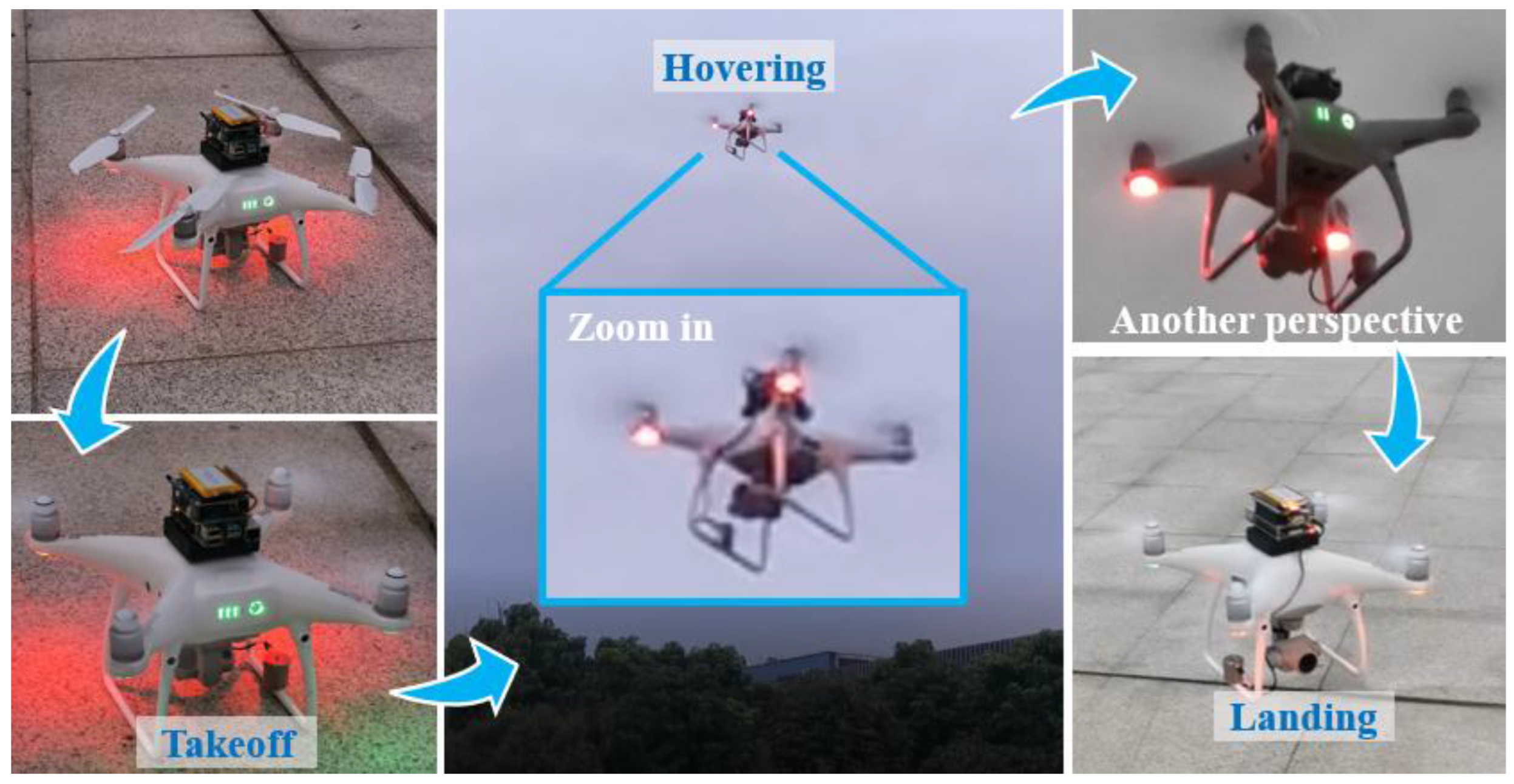
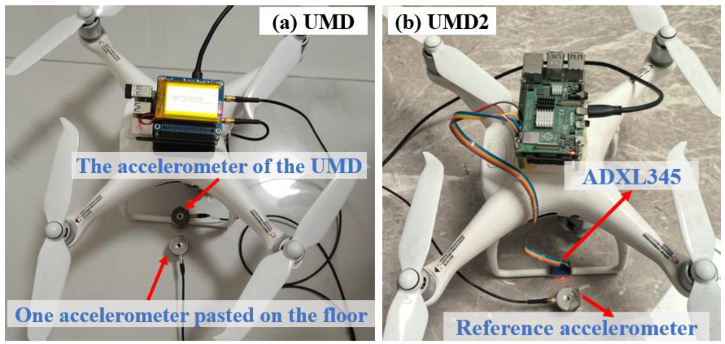
If a UAV and a small-size Raspberry Pi are combined to create a mobile detection platform, it can achieve rapid detection of bridge response, which can be used to detect bridge dynamic characteristics. Based on this idea, we have developed a UAV mobile detection (UMD) device consisting of a Raspberry Pi, a high-precision accelerometer, and a UAV. First, we introduced the device composition and the details of the UMD. Second, to ensure that the device can accurately record bridge vibrations, we proposed a vibration transmission model to test the vibration transmission efficiency and measurement accuracy. Finally, the effectiveness of this method was verified through indoor experiments and field experiments. The technology roadmap is shown in
Figure 1. If this method can be implemented, it can be used to establish a WSN node, which can enable fast and low-cost detection of bridge dynamic characteristics.
Compared with existing portable sensors such as smartphones and Raspberry Pi-based systems, the proposed UMD offers distinct advantages. (1) It eliminates the need for manual sensor installation by allowing the UAV to autonomously reach and contact the measurement point, which is valuable for large or inaccessible bridge sections. (2) Through the establishment of a vibration transmission model, the UMD enables rapid and repeatable measurements without permanent installation, thereby reducing inspection time and cost. (3) measurement resolution analysis could be used for future UMDs or other device designs. However, the measurement duration is limited by the battery capacity, so the UMD is better suited for short-term rapid detection than for long-term fixed monitoring. In addition, unlike camera-based UAV methods that rely on background quality and require motion compensation, our UMD directly measures acceleration at contact, making it immune to camera-shake issues. While Raspberry Pi-based WSNs are possible, our focus here is a roving single-node strategy to minimize cost and deployment effort.
3. Results and Discussion
This section aims to systematically verify the applicability of UMD and clarify its operating conditions. The research includes the following: (i) identifying characteristic features and determining thresholds for the takeoff, hovering, and landing stages based on acceleration time histories to quantify flight stability; (ii) establishing a vibration transmission model through stiffness testing of the landing gear rubber pad, analyzing the effect of damping on transmission rate, and deriving the effective measurement frequency band of UMD; (iii) conducting both indoor and field bridge experiments to compare UMD with fixed reference sensors in the time and frequency domains, thereby evaluating the accuracy of modal frequency identification; and (iv) examining the influence of sensor precision on monitoring performance by manually adjusting acceleration resolution, and determining the minimum resolution threshold required to ensure frequency domain consistency.
3.1. UMD Flight Test Results
In routine bridge inspections, engineers can operate the UAV to determine safe landing locations and guide the UMD to dock at critical positions such as the mid-span or quarter-span of the bridge deck. This process allows vibration measurements to be conducted without interrupting traffic flow. With the development of UAV docking stations, predefined flight paths can be planned so that the UAV autonomously lands on designated bridge locations, records sufficient vibration data, and then departs for recharging. Through repeated inspections, the long-term variation in modal frequencies or vibration amplitudes can be used to identify potential structural deterioration. To support the above procedure, the UMD flight stability and characteristics should be analyzed.
Beyond human eye observation, the stability of UMD could be analyzed through the recorded acceleration, and the characteristics of UMD at different stages can be obtained.
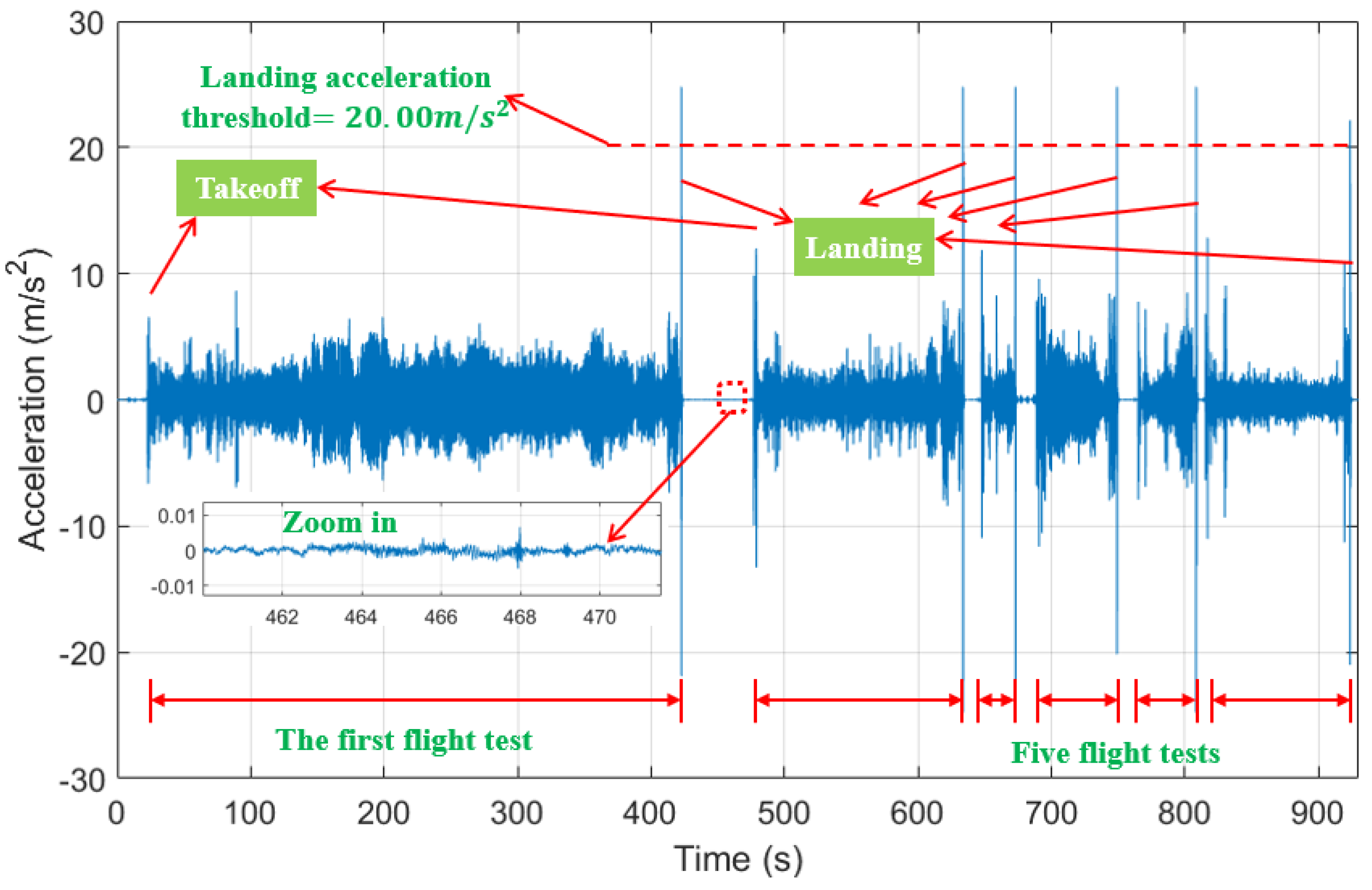
Figure 9 shows the acceleration time history of six consecutive flights. The characteristics of acceleration time history of each flight’s takeoff and landing phases are easy to identify, as shown in
Figure 9. The vertical acceleration of the UMD varies between 3.00
and 8.00
during flight under the influence of its own motion and the wind. In contrast, the acceleration time history during landing detection fluctuates below 0. 01
. Therefore, the vertical acceleration during flight is much greater than that after landing. In addition, UMD has a large acceleration mutation at the moment of takeoff and landing. Comparing takeoff with landing, the acceleration during the landing phase is much greater. This is because the landing gear and the ground collides during landing phase, resulting in large acceleration fluctuations, and the peak accelerations at this stage are greater than 20.00
. Therefore, an acceleration threshold of 20.00
can be set for the acceleration time history to determine whether the UMD is in flight or landing detection mode.
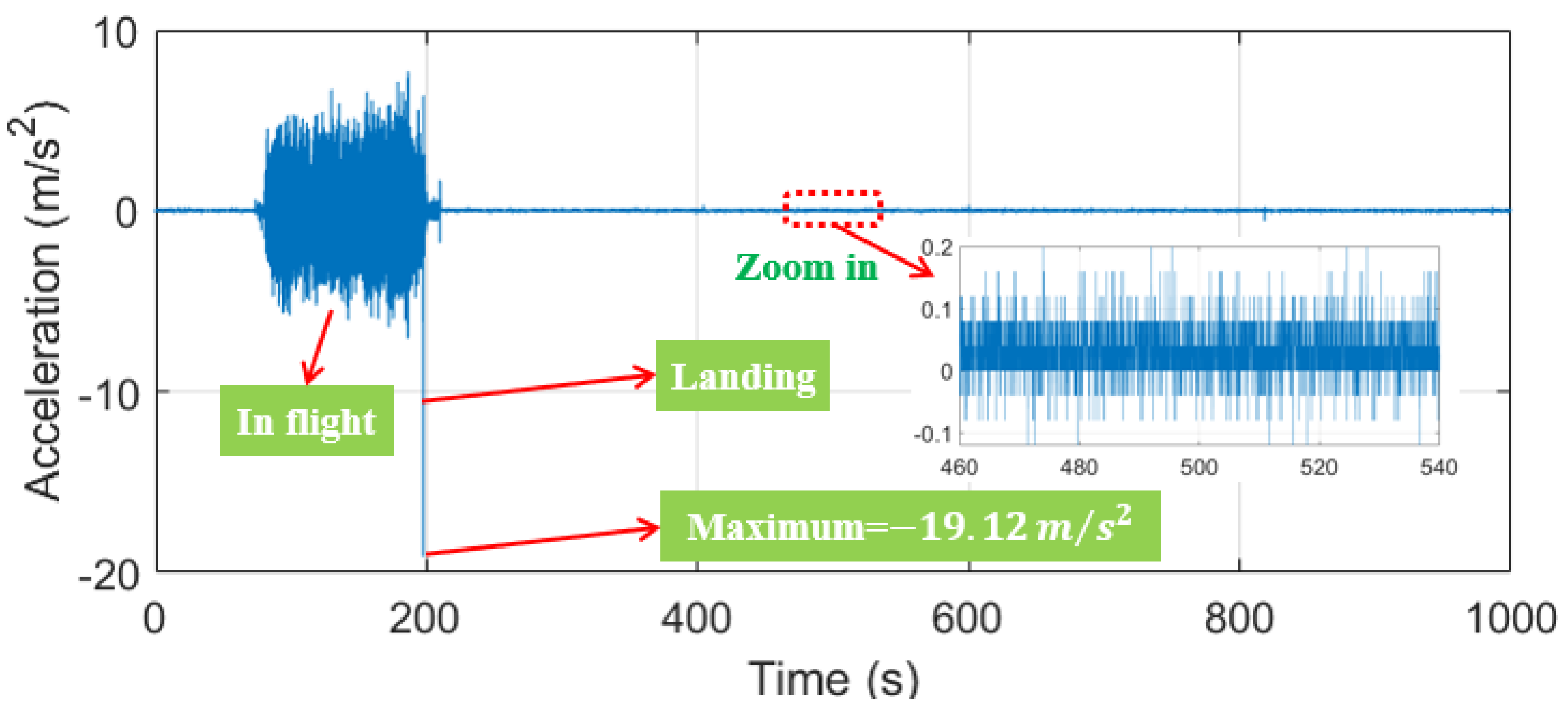
In addition, UMD2 also experienced flight testing, indicating that it can successfully complete flight and landing actions. However, due to structural differences, the acceleration time history of the UMD2’s flight and landing are slightly different from the UMD. As shown in
Figure 10, the flight acceleration of the UMD2 is below 8.00
, and the maximum landing acceleration is −19.12
. Therefore, the status of UMD2 could also be identified through the acceleration amplitude. Zooming in on the graph, the acceleration measurement accuracy of the UMD2 during landing detection is much lower than that of the UMD.
From the above analysis, whether observed by human eyes or analyzed based on acceleration data, UMD has good flight stability and can safely fly and land on one bridge’s deck. In addition, the detection status of UMD and UMD2 can be judged by analyzing the vertical acceleration amplitude during flight.
3.2. Vibration Transmission Analysis
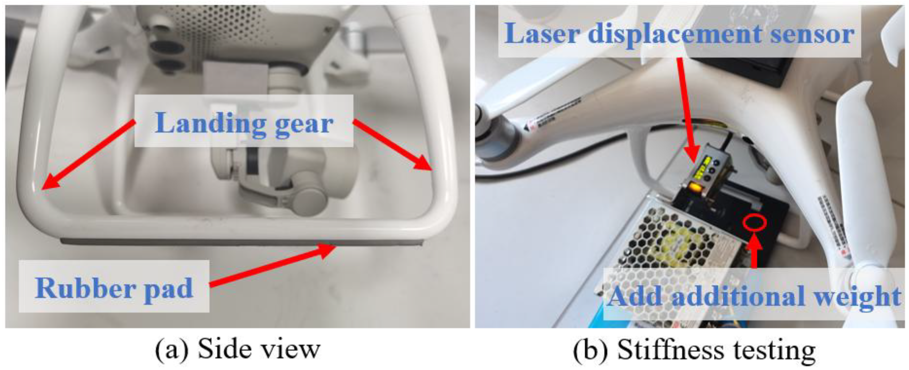
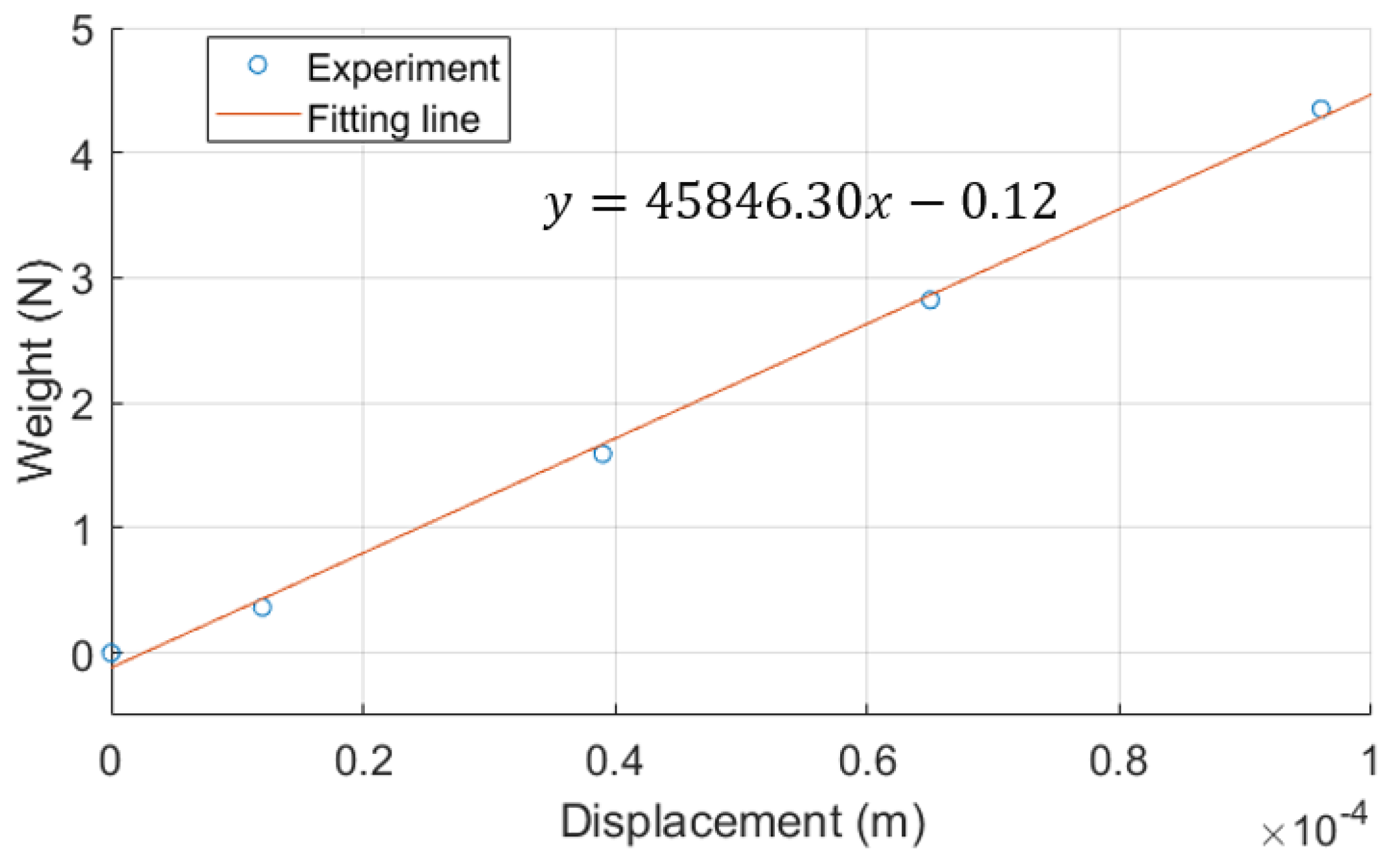
Through the rubber pad stiffness experiment shown in
Figure 6, the experimental results are shown in
Figure 11. The relationship between the applied weight on the rubber pad and the rubber pad’s displacement is basically linear. Using the least squares method, a linear fit is performed on the experimental data, and the fitting line is obtained as shown in the equation in
Figure 11. Moreover, the
of the fitting line is 0.99, which indicates a good linear correlation between the applied force and displacement. Therefore, the stiffness of the rubber pad could be considered as 45,846.30 N/m.
To test the vibration transmission rate of the UMD, the mass of each part of the device has been measured before the experiment, as listed in
Table 1. From
Figure 3, it can be seen that the weight of the UAV, Raspberry Pi, Mcc172, and lithium battery can be considered to be evenly applied on two landing gear. The
and
of UMD are
N/m and 0.93 kg, respectively. The natural frequency
could be obtained. In addition, the
,
, and
of UMD2 are
N/m, 0.84 kg, and 233.62
.
Due to experimental limitations, the empirical value of damping ratio of the rubber pad was adopted. In general, the damping ratios of natural rubber and chloroprene rubber are about 0.05 [
45]. The rubber pads’ material is similar to chloroprene rubber. In this article, we analyze the effect of damping ratios ranging from 0.04 to 0.07, as shown in
Figure 12. Although the damping ratios are different, the curves have a similar tendency as these curves all reach their maximum when
g = 1.00. When
g = 1.00, the larger the damping ratio, the smaller the
Ta is, indicating that the vibration transfer rate is smaller. In addition, when
g = 1.00, resonance occurs, and
Ta will be 7.21~12.54 as damping ratios vary from 0.07 to 0.04. When 0.10 <
g < 1.42,
Ta is always greater than 1.00. In addition, significant differences exist in the curves only when
g is around 1 or
g > 3.00.
In addition, when g is greater than 1.42, Ta is less than 1.00. This means that the acceleration measured by the UMD would be less than that of the bridge. At this time, the rubber pad plays an important role in vibration reduction. If the accelerometer’s vibration of the UMD is much smaller than bridges, this may cause failure of vibration measurement. In this condition, the UMD’s vibration might be less than the minimum resolution of the accelerometer, a bridge’s vibration cannot be monitored accurately. Therefore, when designing UMD, it is necessary to make its larger than 1.42 times the value of the maximum excitation frequency.
When the curve takes the value of g = 1.42, Ta = 0.99, which indicates that the acceleration measured by the UMD, is basically the same as the bridge vibration. From the black dotted line in the figure, we can see that the corresponding bridge’s vibration frequency at this point is 51.95 Hz. As 0.00~51.95 Hz can already meet the requirements of dynamic characteristic testing of most bridges, the proposed UMD in this paper has a good measurement range of excitation frequency. As a comparison, UMD2 has a relatively small mass and a slightly larger , while its vibration transmission will hardly decay when stimulated from 0.00 to 52.61 Hz.
It should be noted that the natural frequency ωn in this model represents the isolator’s property within the UMD rather than the bridge structure itself. The value of ωn depends on the stiffness of the isolator and the mass of the UMD. When a different rubber material is used, ωn and the damping ratio can be re-identified through a short calibration test, and the same transmissibility formulation remains applicable.
3.3. Results of Indoor Experiments
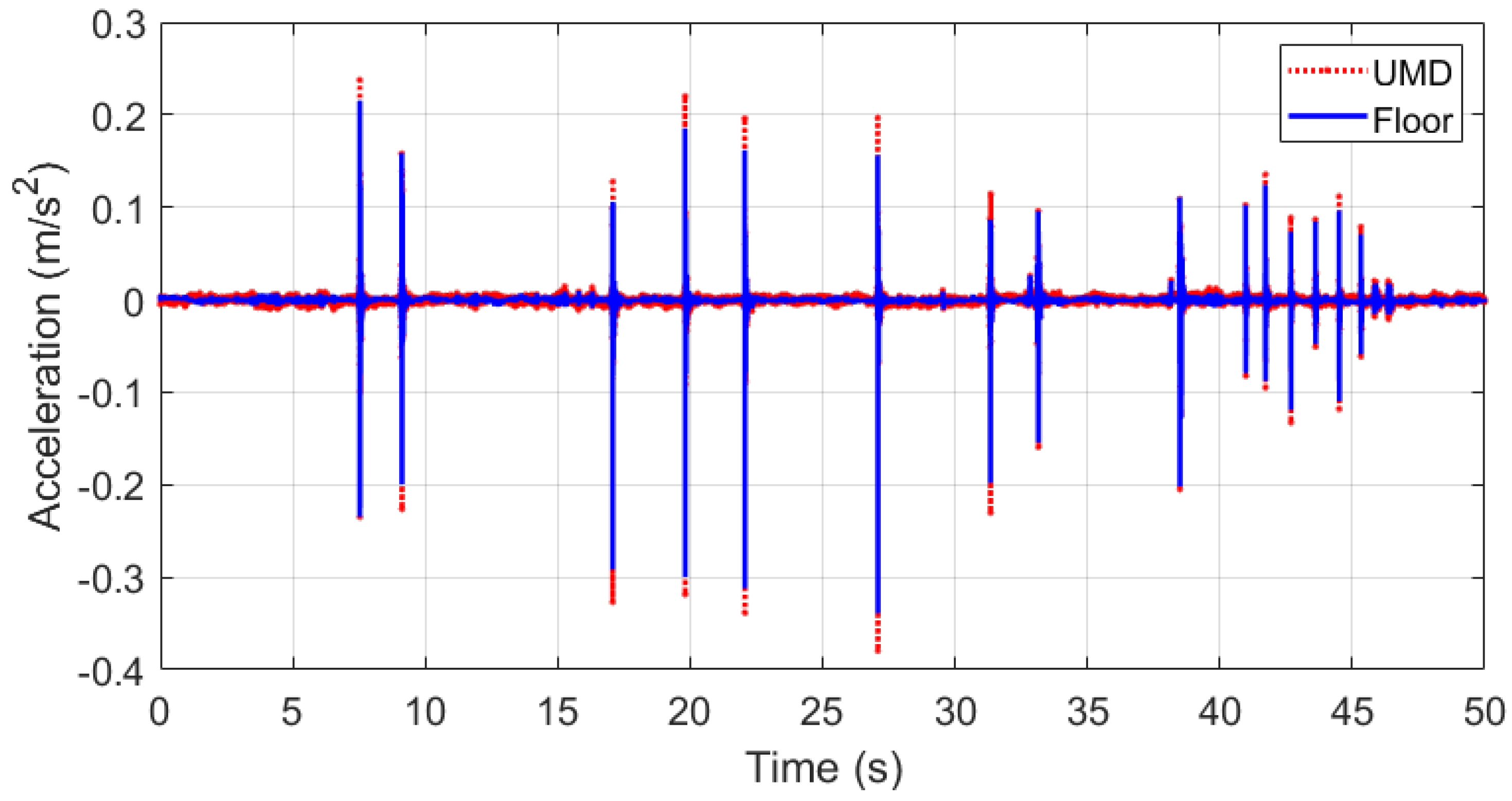
The results of aforementioned indoor comparative experiment are shown in
Figure 13. It can be seen that the UMD’s acceleration and the floor’s acceleration were consistent as time increased. The acceleration monitored by the UMD was slightly greater than that of the floor. The reason why the UMD’s acceleration is greater can be explained through the results in
Section 3.2. This is because the excitation frequency is below 51.95 Hz, the corresponding
g is less than 1.42, and
Ta is thus greater than 1.00. As the excitation frequencies are different, the ratio of UMD’s vibration to floor’s vibration is also different, but the trend of the entire acceleration time history is the same.
Because Ta is the vibration amplitude ratio between the UMD and the floor, the UMD’s measurement error basically follows the pattern of percentage error. Therefore, when the floor’s vibration was small, the data of the two methods were relatively close to 0.00 . When the floor’s vibration increased, the difference between the two methods also increased.
If the two kinds of data in
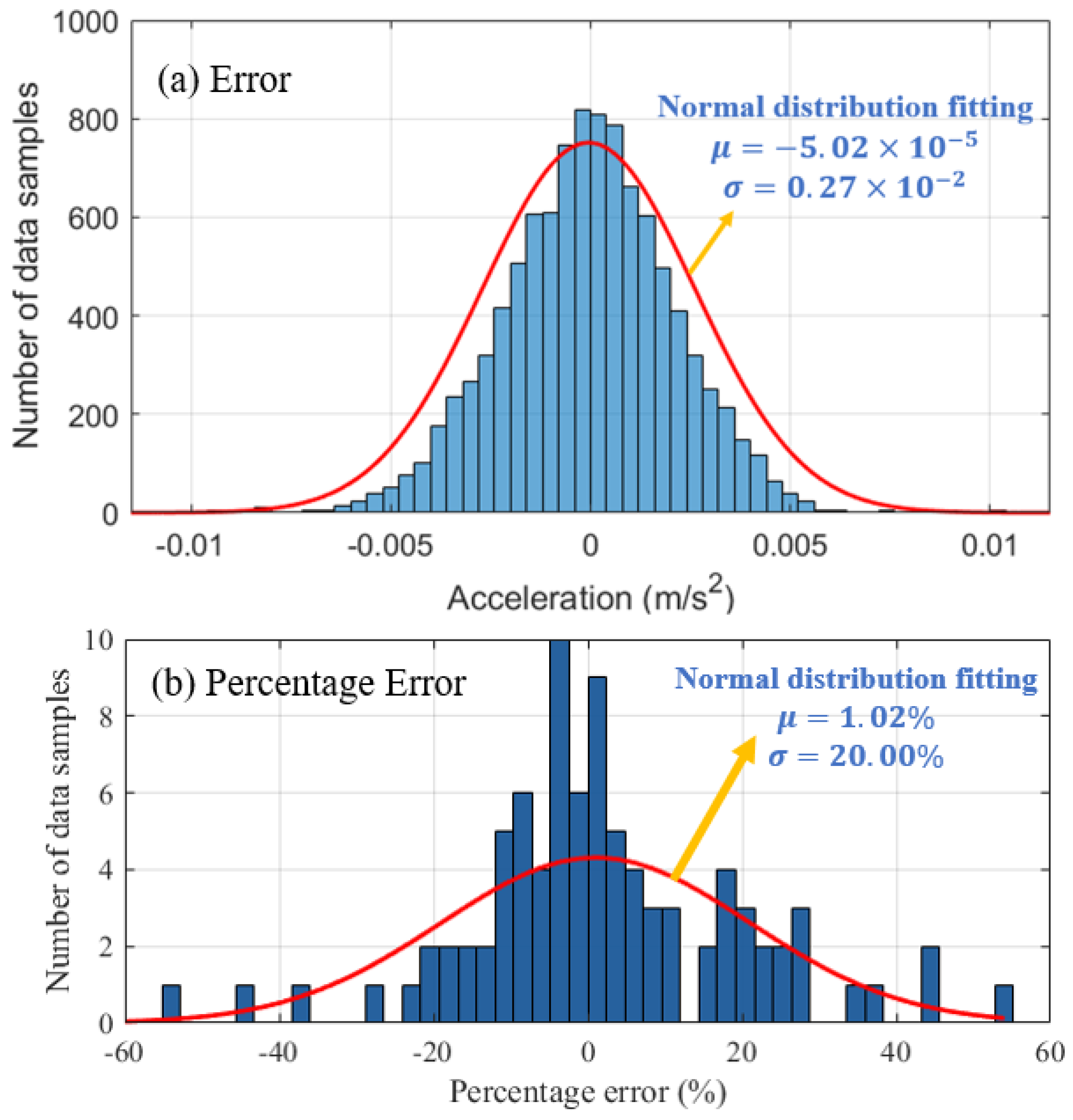
Figure 13 are subtracted from each other, the obtained data difference basically follows a normal distribution as shown in
Figure 14. If a normal distribution is fitted to the data difference, the mean is
and the standard deviation is
. According to the characteristics of normal distribution, 99.00% of the data falls within
. Therefore, the acceleration error measured by the UMD lies within the range
. Percentage error distribution of the indoor experiments are much larger than
Figure 14a, with standard deviation 20.00%.
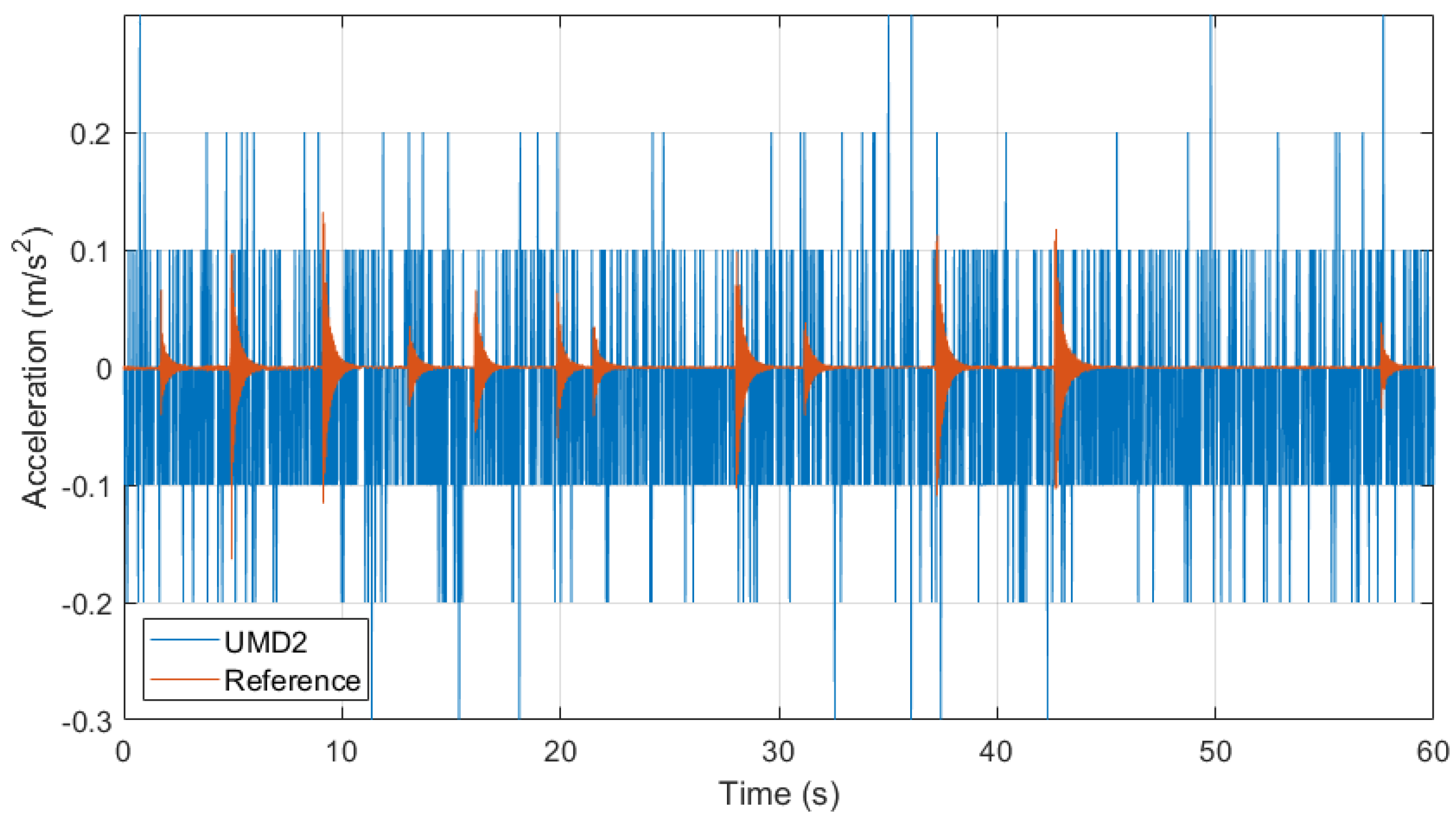
To verify the performance of UMD2 in the same environment, an indoor test was performed using the ADXL345-based UMD2 device under human jumping excitation. The acceleration time histories measured by UMD2 and the reference accelerometer are shown in
Figure 15. It can be observed that the UMD2 signal contains substantial random noise and lacks a consistent response pattern, making it unable to reproduce the actual floor vibration captured by the reference sensor.
This is primarily due to the limited sensitivity and resolution (0.04 m/s2) of the ADXL345 accelerometer, which is inadequate for detecting small vibration amplitudes (<0.01 m/s2) typical of indoor excitation.
3.4. Results of Field Experiments
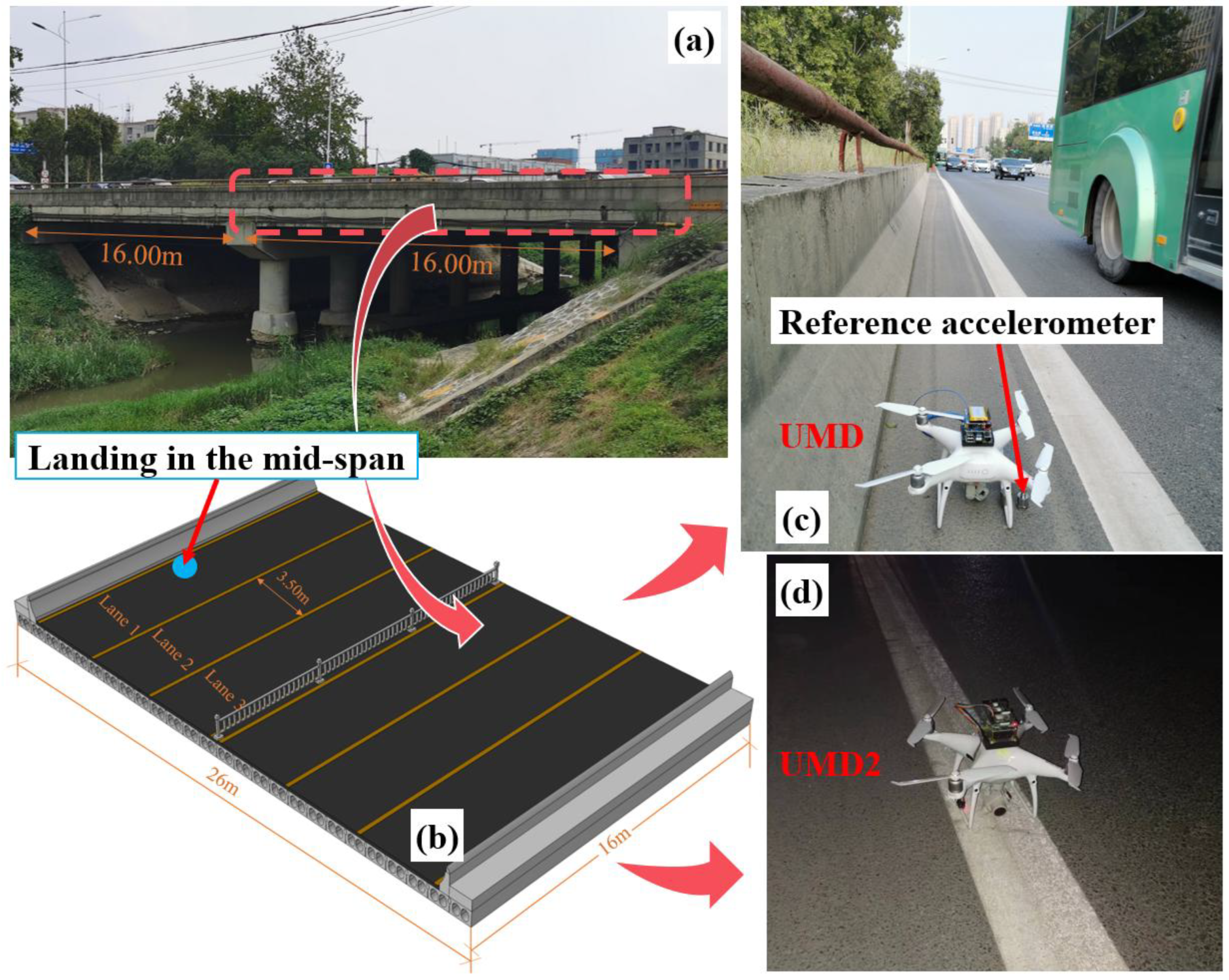
This section presents the field validation of the proposed UMD and UMD2 systems and analyzes their measurement accuracy under real bridge operating conditions. The objective is to verify the UMD’s ability to capture bridge vibration responses and identify modal frequencies through comparison with a reference accelerometer.
Section 3.4.1 describes the monitoring results of the UMD, including time and frequency domain analyses and statistical error evaluation.
Section 3.4.2 presents the performance of the UMD2, highlighting the limitations of its low-cost MEMS accelerometer. Finally,
Section 3.4.3 investigates the influence of accelerometer resolution on the monitoring results to determine the minimum required resolution for reliable vibration detection. Together, these analyses confirm the feasibility and accuracy of the proposed UMD system for field bridge vibration monitoring.
3.4.1. Results of UMD
In the field experiment, before the UMD took off, acceleration data collection had already started. After the UMD landed on the bridge, the acceleration time history of the detection results could be identified using the method of
Section 3.1.
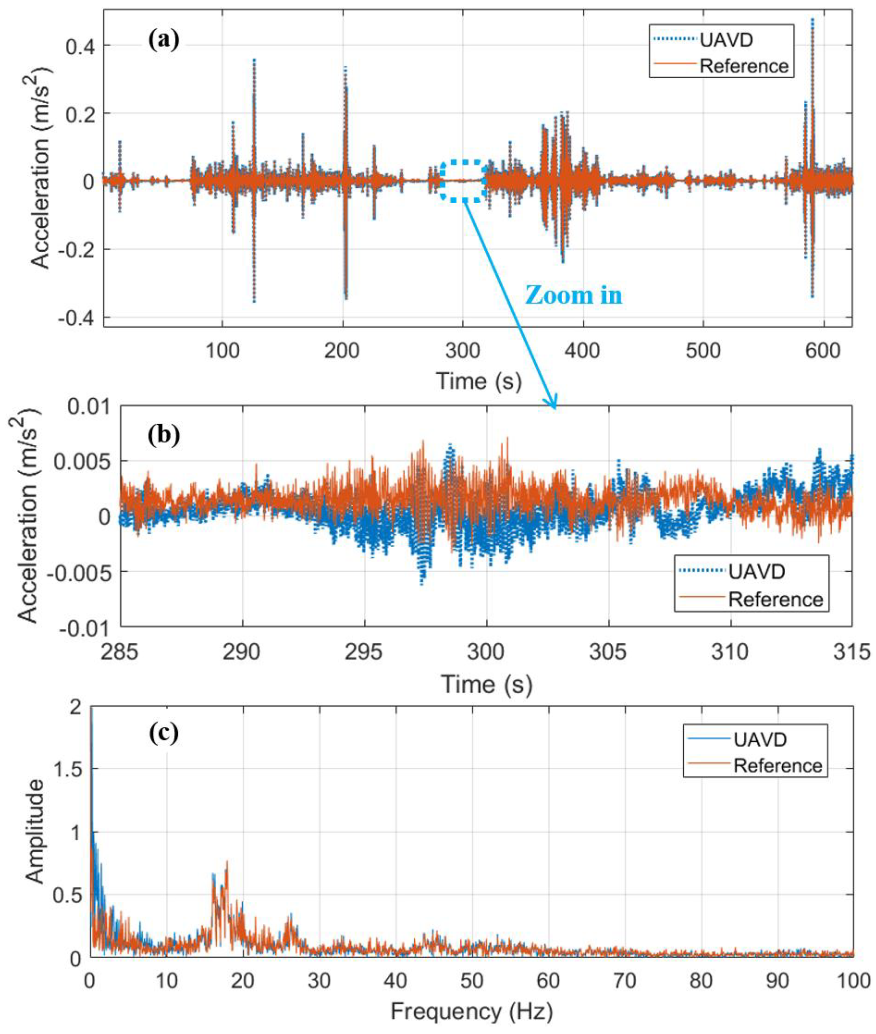
Figure 16a shows the detection results for 10.00 min. It is clear that the acceleration of the UMD basically agrees with the reference sensor, and the error is relatively small. During the measurement, the impact loads generated by the passing vehicles are significant, and the maximum acceleration exceeds 0.44
. The amplitude of the UMD signal is slightly larger than that of the reference sensor, particularly under ambient and vehicle excitation. This difference can be explained by the vibration transmissibility
where the frequency ratio
falls in the range
, for which
. Thus, the acceleration amplitude measured by the UMD is theoretically amplified relative to the bridge deck, and the discrepancy increases as the excitation frequency approaches the natural frequency of the isolator (
).
Nevertheless, when there is no vehicle passing through, the vibration amplitude of the bridge is much smaller. For example,
Figure 16b is an enlarged view of the data from 285.00 s to 315.00 s. Under environmental excitation, the bridge deck’s acceleration is less than 0.01 m/s
2. In addition, unlike the impact effect of a passing vehicle, under environmental excitation, larger error exists between the vibration of the UMD and the bridge deck. This error may be caused by the inaccuracy of the vibration transfer model; the current vibration transmission model simplifies the system to in-plane motion (XY plane) and neglects small out-of-plane vibrations (YZ plane and XZ plane) of the landing gears, as shown in
Figure 5. This simplification may cause minor rotational effects and amplitude differences. For example, aerodynamic micro-disturbances near the landing position may contribute to UMD’s vibration in YZ plane and XY plane and induce these variations.
However, as shown in
Figure 16c, even though there are differences in the amplitude of vibration under environmental excitation, the frequency domains are basically the same. Compared with the reference sensor, the UMD could detect the main frequencies of 16.07 Hz and 17.93 Hz. Therefore, these amplitude variations do not affect the identification of modal frequencies, confirming that the proposed UMD is suitable for rapid bridge vibration detection.
To more accurately measure the monitoring accuracy of UMD, the difference between the monitoring data of UMD and the reference sensor was calculated and plotted in
Figure 17. The error is approximately normally distributed, with a mean and a variance of
and
, respectively. Compared with
Figure 14, the variance of the field experiment is smaller, the same trend could be found in the percentage error. Additionally, as shown by the yellow dashed box, there are more samples with an error greater than
. This suggests that the data on the right side are more dispersed while the data on the left side are more concentrated. This may be due to the vibrations transferred between the UMD and the bridge deck, as the bridge experiences varying frequencies of forced movement under different weights and speeds of vehicle loads. As shown in
Figure 12, if the forced movement frequency of the bridge is around 35.36 Hz, the acceleration amplitude measured by UMD will be 7 to 12 times greater than the bridge deck’s vibration. If the forced movement frequency is far away from 35.36 Hz, the difference between the UMD and the bridge deck would also decrease accordingly. Therefore, there are some differences between the error distribution and a standard normal distribution. However, the error in the field experiment is still small enough, which means that the wake turbulence and other noises generated by the passing vehicles do not overly affect the monitoring of the UMD.
Figure 18 shows the power spectral density (PSD) of the acceleration signal collected during a representative field test. The reference accelerometer data was used to identify modal frequency peaks, indicated by red circles.
The first vertical bending mode was identified at 3.88 Hz, and the third bending mode at 34.75 Hz, with their corresponding theoretical mode shapes annotated. These results are consistent with the expected modal frequencies of a 16 m simply supported span, where the modal frequencies theoretically follow a quadratic relationship with mode number:
[
46]. Thus, the third mode is expected to occur near
, which agrees well with the observed
. A corresponding PSD analysis of the UMD data yielded similar peaks, with the first mode identified at 3.75 Hz and the third mode at 34.88 Hz, resulting in a relative frequency deviation of less than 3.40% for the first mode and 0.37% for the third mode. This confirms the capability of the UMD to detect bridge modal frequencies with good accuracy under operational conditions.
It is also noted that low-frequency peaks below 1.00 Hz (e.g., at 0.38 Hz and 0.5 Hz) were detected by UMD and reference sensor. These are not considered structural modal frequencies but may arise from quasi-static motion of the bridge, such as thermal drift, gradual traffic loads, and aerodynamic perturbations. In a simply supported bridge, the first vertical bending mode generally represents the lowest dynamic mode and dominates the structural vibration response, while higher-order vertical bending, torsional, and lateral bending modes appear at progressively higher frequencies. Therefore, frequency components below 3.75 Hz are unlikely to correspond to structural modes. Instead, they reflect the combined influence of quasi-static excitation and long-period bridge motion under variable external conditions. Therefore, the modal analysis in this study focuses on frequency components above 3.00 Hz.
In addition, the second vertical bending mode was not observed in the PSD results, neither from the reference sensor nor from the UMD. This is mainly attributed to the sensor location: both the UMD and the reference accelerometer were placed approximately at the mid-span of the 16.00 m bridge. For a simply supported beam, the second bending mode exhibits a node (inflection point) at mid-span, where the vertical displacement—and hence acceleration—is theoretically zero. As a result, the second mode’s vibration energy is not effectively captured by sensors located at this point.
A frequency component 8.75 Hz was also observed in both the UMD and reference sensor spectra. Because this study employed a single measurement point at the mid-span, the exact mode shape corresponding to this frequency cannot be conclusively determined—identifying torsional, lateral bending mode or higher-order modes typically requires multiple synchronized sensors or repeated measurements at different locations [
47]. Nevertheless, the simultaneous appearance of the 8.75 Hz peak in both sensors indicates that it represents a genuine structural vibration of the bridge rather than noise.
Therefore, although the small amplitude differences observed in acceleration due to the characteristics of absolute transmission rate, the frequency domain comparison (
Figure 16 and
Figure 18) shows that the dominant modal frequencies identified by the UMD agree with those from the reference sensor, which could be used for future structural damage identification.
3.4.2. Results of UMD2
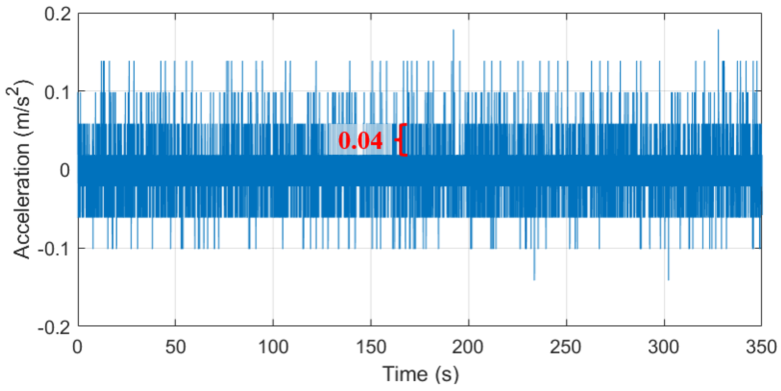
The UMD2 was also tested during the field experiment, and the monitoring results after landing on the bridge deck are shown in
Figure 19. It could be seen that the monitoring results of the UMD2 are not accurate enough, and the monitoring signal is similar to an electrical signal. No matter under vehicle excitation or environmental excitation, UMD2 was unable to monitor the bridge’s vibration. The reason for this result is that the accuracy of the ADXL345 sensor is relatively low, with a minimum acceleration resolution of 0.04 m/s
2, which cannot identify the small vibrations of the bridge deck. From the figure below, UMD2 has a relatively wider excitation frequency measurement range (0.00~52.61 Hz), and the bridge deck’s vibration would be amplified to different extents. However, the vibration amplification cannot compensate for the insufficient accuracy of the ADXL345 sensor, resulting in poor monitoring results. Obviously, the proposed UMD is more suitable for bridge vibration monitoring than UMD2.
3.4.3. Monitoring Resolution Comparison
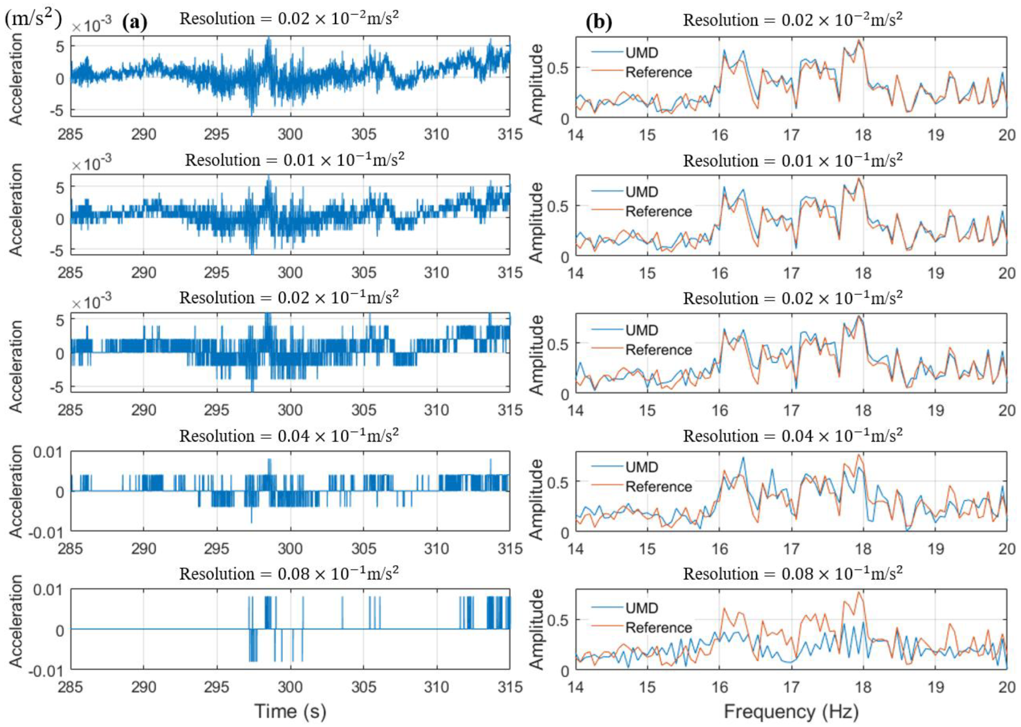
To explore the impact of monitoring resolution on monitoring results, the time domain and frequency domain results of the UMD at different monitoring resolutions are presented. The monitoring results of the UMD are approximately processed to approximate different minimum resolutions, as shown in
Figure 20a. In the time domain, when the acceleration resolution is below
, the monitoring results have good monitoring accuracy and can restore the bridge vibration under environmental excitation. When the resolution is
, the monitoring results begin to show a sawtooth-like result, and the trend of the acceleration time history is still consistent with the high-resolution results. As the resolution gradually decreases, this sawtooth-like monitoring result becomes increasingly apparent. When the resolutions are
or
, the monitoring results become similar to
Figure 20, which resembles random voltage signals. This indicates that to better monitor the acceleration time history, the resolution of the acceleration sensor needs to be at least
.
In addition, we compared the impact of changing the acceleration resolution on the frequency domain results using Formula (4). As shown in
Figure 20b, when the precision is
,
, and
, the monitoring results of UMD are very similar to the reference results. However, when the resolution reaches
, the differences between the two begin to increase, and the UMD’s frequency domain begins to show errors. As the resolution continues to decrease to
, the monitoring results of UMD have large errors and can hardly reflect the frequency domain features of the original vibration signal. Therefore, for frequency domain measurements, the acceleration resolution of UMD’s accelerometer should be at least
. Therefore, for UMD2, its acceleration resolution of
(
Figure 20) cannot meet the minimum resolution requirement, so it cannot achieve monitoring requirements in both time domain and frequency domain.
However, if only the monitoring results in
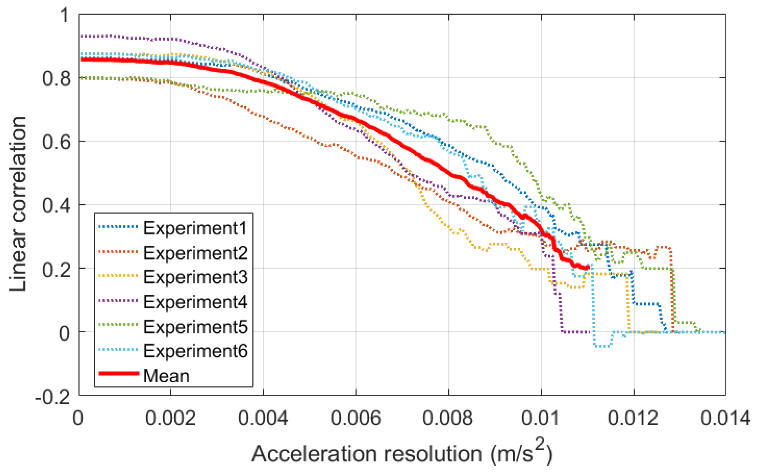
Figure 20b are analyzed, there may be uncertainty. Therefore, it is necessary to analyze multiple monitoring results under environmental excitations and calculate the linear correlation coefficient between the frequency domain data of the UMD and the reference sensor.
Figure 21 shows the linear correlation coefficients of the frequency domain of the UMD and the reference of six experiments under environmental excitations. As resolution increases, the linear correlation coefficients of the six experiments gradually decrease. When the resolution is smaller than
, the correlation coefficients remain almost unchanged. At a resolution of
, the average correlation coefficient of the six experiments is 0.85, indicating that the monitoring data can adequately reflect the bridge’s vibration frequency. When the resolution is higher than
, the correlation coefficient gradually decreases. With a resolution of
, the average correlation coefficient is 0.20, indicating that the UMD’s monitoring data can no longer provide useful vibration information in frequency domain. This again demonstrates that the resolution of UMD2 (
) is insufficient for bridge vibration measurements. Therefore, the minimum acceleration resolution of UMD’s accelerometer is
.
When the resolution becomes coarse (≥0.11 × 10
−1 m/s
2), the UMD’s frequency domain signal becomes nearly constant, with a standard deviation of zero; as a result, Pearson correlation function, as shown in Formula (5), could not be calculated. In such cases, the mean correlation coefficient cannot be computed, and thus the mean curve terminates earlier in
Figure 21. This behavior reflects the loss of frequency domain information at very low resolutions rather than missing data.
In summary, whether UMD can accurately monitor the vibration of bridges depends on the vibration transmission rate and the accuracy of the sensor. In other words, it depends on the stiffness of the rubber pad, the mass of UMD, and the accuracy of the acceleration sensor. If the rubber pad’s stiffness of landing gear is small, the rubber pad may play a shock-absorbing role, resulting in a smaller monitored acceleration and ultimately may lead to insufficient monitoring accuracy of UMD. In addition, if the accuracy of the accelerometer is less than , UMD will be unable to accurately monitor the frequency domain’s characteristics of bridge vibration.
4. Conclusions
Bridges are critical components of transportation infrastructure, yet traditional methods of detecting bridges’ dynamic responses are often time-consuming and costly. To address this issue, a novel UMD was designed, and the feasibility of the method was verified in this article. Through the analysis in this article, the following conclusions can be drawn:
- (1)
The proposed UMD was successfully verified through flight, indoor, and field bridge experiments, demonstrating stable flight performance and reliable vibration acquisition after landing.
- (2)
A vibration transmission model was developed to describe the bridge–UMD–accelerometer interaction. Experimental results confirmed that the UMD can accurately detect bridge frequencies within the range of 0.00–51.95 Hz, and the model is transferable to other UMD configurations after updating the isolator parameters.
- (3)
The measurement error of the UMD lies within , and the relative modal frequency deviation compared with the reference accelerometer was less than 3.40%, verifying that the proposed model can reliably capture bridge modal characteristics under operational excitation.
- (4)
Sensitivity analysis showed that an accelerometer resolution of at least m/s2 is required to ensure accurate frequency domain identification, establishing a design guideline for future UMD configurations.
- (5)
Comparative experiments demonstrated that the MEMS-based UMD2 device, although lighter and more stable in flight, exhibited insufficient accuracy for dynamic response monitoring, highlighting the advantage of using higher-resolution IEPE sensors in practical applications.
In contrast to traditional fixed sensor networks or vision-based non-contact monitoring methods, the proposed UMD provides a mobile and contact-based alternative that combines UAV mobility with onboard data acquisition. This integration allows accurate vibration measurements without permanent installation, bridging the gap between long-term SHM systems and short-term inspection methods. Therefore, UMD can be regarded as a complementary extension of existing SHM technologies, enabling rapid, cost-effective, and flexible assessments for bridges and other structures that are not equipped with permanent monitoring devices.
However, the UMD proposed in this study has, so far, only been used for single-point bridge measurements and is therefore incapable of performing bridge modal identification. At present, the UMD operates manually for flight and landing, without implementing key-position localization or automated path planning for specific bridge types. Future work will focus on the following aspects:
- (1)
Extending the proposed method toward multi-UMD synchronized monitoring. By incorporating Global Positioning System-based or network-time-protocol-based timestamp synchronization, a time precision better than 1 ms can be achieved, allowing multiple UMDs to record structural vibrations simultaneously.
- (2)
For specific bridge types, multiple UMDs will be coordinately deployed through formation planning and reference-point arrangement to capture the vibration responses across the entire span.
- (3)
The UMD docking mechanism will be improved to enable stable attachment to taller or irregular structures, thereby supporting multipoint measurement and expanding its applicability to a wider range of engineering scenarios.
- (4)
Refining the UMD vibration transmission model to include three-dimensional coupling effects for improved accuracy under small-amplitude excitations.
- (5)
Applying for rapid post-earthquake bridge assessment. Multiple UMDs could be deployed to land simultaneously at key bridge locations, such as mid-span, to rapidly extract the bridge modal frequencies after an earthquake. By comparing these results with the pre-event modal characteristics, possible structural damage can be promptly identified, supporting rapid decision-making for bridge safety evaluation.


