Article

Evaluation of the Adaptive Behavior of a Shell-Type Elastic Element of a Drilling Shock Absorber with Increasing External Load Amplitude

by
Andrii Velychkovych
1,*,
Vasyl Mykhailiuk
2 and
Andriy Andrusyak
1
1
Department of Construction and Civil Engineering, Ivano-Frankivsk National Technical University of Oil and Gas, 15 Karpatska Str., 76019 Ivano-Frankivsk, Ukraine
2
Department of Oil and Gas Field Machinery and Equipment, Ivano-Frankivsk National Technical University of Oil and Gas, 15 Karpatska Str., 76019 Ivano-Frankivsk, Ukraine
*
Author to whom correspondence should be addressed.
Vibration 2025, 8(4), 60; https://doi.org/10.3390/vibration8040060
Submission received: 16 August 2025 / Revised: 18 September 2025 / Accepted: 28 September 2025 / Published: 2 October 2025
(This article belongs to the Special Issue Vibration Damping)

Abstract

Vibration loads during deep drilling are one of the main causes of reduced service life of drilling tools and emergency failure of downhole motors. This work investigates the adaptive operation of an original elastic element based on an open cylindrical shell used as part of a drilling shock absorber. The vibration protection device contains an adjustable radial clearance between the load-bearing shell and the rigid housing, which provides the effect of structural nonlinearity. This allows effective combination of two operating modes of the drilling shock absorber: normal mode, when the clearance does not close and the elastic element operates with increased compliance; and emergency mode, when the clearance closes and gradual load redistribution and increase in device stiffness occur. A nonconservative problem concerning the contact interaction of an elastic filler with a coaxially installed shaft and an open shell is formulated, and as the load increases, contact between the shell and the housing, installed with a radial clearance, is taken into account. Numerical finite element modeling is performed considering dry friction in contact pairs. The distributions of radial displacements, contact stresses, and equivalent stresses are examined, and deformation diagrams are presented for two loading modes. The influence of different cycle asymmetry coefficients on the formation of hysteresis loops and energy dissipation is analyzed. It is shown that with increasing load, clearance closure begins from local sectors and gradually covers almost the entire outer surface of the shell. This results in deconcentration of contact pressure between the shell and housing and reduction of peak concentrations of equivalent stresses in the open shell. The results confirm the effectiveness of the adaptive approach to designing shell shock absorbers capable of reliably withstanding emergency overloads, which is important for deep drilling where the exact range of external impacts is difficult to predict.

1. Introduction

During deep drilling of oil, gas, and geothermal wells, drilling equipment is subjected to dynamic loads arising from the interaction of the bit with rock, as well as from the specifics of nonlinear dynamics of the long drill string [1,2,3,4]. An important task for modern drilling technology is the effective management of such dynamic loads, as ignoring them can lead to premature wear or even destruction of tools and downhole motors, reduced drilling efficiency, and increased risks of emergency situations [5,6,7,8]. In this direction, drilling shock absorbers, also known as shock subs, serve as key elements of the vibration protection system [9,10].
The main function of drilling shock absorbers is to reduce dynamic overloads to ensure stable tool operation in complex geological conditions [11,12]. During drilling, axial (bit bounce), torsional stick-slip, and whirl vibrations occur, which are often combined, amplifying the harmful impact on equipment [13,14,15]. This can cause loss of control over the drilling process and lead to mechanical damage at various levels of the drilling system, from the bit and downhole motor to the top drive [16,17].
When designing drilling shock absorbers, particular complexity lies in the selection and practical implementation of the elastic element, which must simultaneously meet mutually competing requirements for mechanical properties and geometric parameters. On one hand, the shock absorber must provide sufficient system compliance to effectively absorb impulse and oscillatory loads. On the other hand, it must withstand significant static and vibration loads, absorbing them without loss of strength. These requirements are significantly complicated by restrictions on the transverse dimension, since the diameter of the drilling tool is regulated by the conditions of passage through the wellbore and compatibility with other string components. As a result, the allowable space for placing the elastic element is extremely limited, which excludes the use of most traditional vibration protection solutions. Therefore, for the design of drilling shock absorbers, we propose using shell elastic elements and shell dampers [18,19]. This is a relatively new functional class of vibration protection devices, which by the principle of energy absorption are classified as friction dampers.
Among such devices, dampers with dry friction occupy a special place, which due to their simple design, small dimensions, and low maintenance costs have gained wide application in vibration protection systems. Dry friction technologies are effectively implemented to reduce vibration loads in critical components of modern equipment, particularly in gas turbine engine parts, blade disks, and in cardan transmissions of helicopter tail rotors [20,21,22]. In addition, effects associated with the operation of Coulomb-type dampers find practical application in material mixing equipment, as well as in household appliances, for example, in washing machines [23,24]. The versatility and reliability of friction dampers ensure their popularity in both complex engineering systems and mass production, where efficiency and durability are important [25,26,27,28].
A feature of shell friction dampers is the use of a thin-walled shell as a load-bearing element, which provides the force closure necessary for contact interaction between damper parts. In addition, the shell directly participates in the process of deformation energy absorption. Note that force closure is a condition in which contact between parts is ensured not by geometric fixation, but by pressing forces, which allows implementing friction damping [29]. The load-bearing shell is usually made of high-strength steel or composite material; it can be open (with a longitudinal or helical cut) or closed—depending on stiffness requirements and deformation type [18,19,30]. Its geometry and boundary conditions determine the elastic characteristics of the system, while the internal filler ensures the implementation of the dissipative component.
The operating principle of a shell damper consists in converting external dynamic loads into potential energy of elastic deformation of the shell with partial dissipation of the supplied energy due to dry friction effects. The advantages of shell dampers lie in high specific energy capacity, compactness, relatively low mass, as well as the ability to adjust elastic-damping characteristics [18,19].
In real designs of shell dampers, there is often a need to integrate an axial through channel. For drilling shock absorbers, such a channel is necessary for pumping drilling fluid through the drill string to clean the bottom hole from cuttings and rock fragments [31,32]. The working medium in this case is abrasive, so to increase the wear resistance of the inner surface of the through channel, specialized protective coatings are applied [33,34,35].
Adaptive and nonlinear isolation spans dry-friction concepts with amplitude-dependent hysteresis, quasi-zero-stiffness (QZS) mechanisms that combine positive and negative stiffness to depress the natural frequency, and semi-active solutions. Recent overviews of QZS isolators and their engineering trade-offs provide useful context, as do applied vibration studies in industrial machinery [36,37,38]. In contrast, the present shell-type elastic element with a designed radial clearance delivers a passive, load-adaptive response via progressive contact under increasing axial load—well aligned with compact drilling hardware.
The mechanical behavior of shell friction dampers should be described as the interaction of elastically deformed bodies with friction on contact surfaces under cyclic loading. From a mathematical point of view, this leads to the formulation of mixed contact problems that have an essentially nonlinear character due to the presence of dry friction and variable structure of contact zones. The description of such interactions represents one of the fundamental problems of solid mechanics [39,40,41,42]. Today, the literature has developed analytical [43,44,45,46] and numerical [47,48,49,50] methods based on continuum models that allow investigating characteristic patterns of friction and determining key parameters of frictional interaction of bodies. Particular complexity is presented by problems for thin-walled shells, in which zones of partial contact, stress concentrations near edges, as well as effects of geometric or material defects arise [51,52,53,54]. A separate interest is aroused by the class of problems concerning the phenomenon of contact interaction of crack edges in thin-walled structural elements [55,56,57,58,59].
This research is devoted to the analysis of contact interaction of a deformable filler with coaxially installed shaft and open cylindrical shell, which are placed inside the rigid housing of a drilling shock absorber with a small radial clearance. At initial loading stages, the system behaves as compliant, i.e., the open shell deforms under the action of the filler without contact with the shock absorber housing. However, under conditions of intense external impact, the clearance closes, and the shell comes into contact with the housing, which radically changes its resistance to loading. Since the housing stiffness significantly exceeds the shell stiffness, the transition from free deformation to the mode of contact with the housing leads to a significant increase in the effective stiffness of the shock absorber. Such a mechanism provides an adaptive response of the damper to load changes, particularly effective energy absorption during short-term dynamic or impact influences. In addition, contact with the housing performs a safety limiting function—it prevents excessive deformation of the shell and prevents its destruction under emergency overload conditions. Previous studies mainly considered drilling shock absorbers with solid shells, in which contact with the housing was not provided. The proposed model for the first time takes into account the influence of local contact between the open shell and the shock absorber housing.
The aim of this work is to construct a numerical model of a shell elastic element for a drilling shock absorber, taking into account the contact interaction of the load-bearing shell with the housing when the radial clearance between them is exhausted. The model will also take into account friction between the filler and shell and between the filler and shaft. For this purpose, within the framework of the study, a mixed contact problem will be formulated, implemented as a finite element model, and an approach to constructing a characteristic deformation diagram of the system depending on cyclic loading will be proposed.

2. Materials and Methods

2.1. Design Features of an Adaptive Drilling Shock Absorber with a Shell Elastic Element

Drilling shock absorbers are usually installed in the lower part of the string—between the drill bit and the drill collar, or between the bit and the downhole motor. At the same time, depending on specific technical requirements, it is possible to place the shock absorber in other zones of the string to solve local vibration protection tasks.
Depending on the direction of vibration damping, drilling shock absorbers are classified into shock absorbers for damping longitudinal (axial) vibrations; shock absorbers for damping torsional vibrations; shock absorbers capable of damping both longitudinal and torsional vibrations. Equipping the shock absorber with calibrating, centering, or expanding elements allows partial damping of transverse vibrations as well.
By the nature of load perception, drilling shock absorbers are divided into single-acting and double-acting devices. Single-acting shock absorbers are designed primarily for operation under compression conditions, so they are installed in the lower part of the drill string, where compressive loads dominate. In contrast, double-acting shock absorbers are capable of functioning effectively under both compression and tension, which allows their use at any location along the string length, particularly in transitional or non-uniformly loaded sections.
Structurally, a drilling shock absorber comprises two primary functional units. The first is the elastic element, which stores and dissipates vibratory energy. The second is the torque-transmission unit, which conveys rotation from the drill string to the bit. Depending on the configuration, the assembly may also include auxiliary components that support normal operation, enhance reliability, and facilitate maintenance.
Figure 1a presents the design of a drilling shock absorber with a shell elastic element (basic configuration). The main feature of this device is that the load-bearing link of the elastic element is made in the form of a steel cylindrical shell with a cut along the generatrix (Figure 1b). Such a constructive modification transforms the steel cylindrical shell into a conditionally orthotropic system—its radial stiffness is significantly reduced, which contributes to effective vibration absorption, while the axial stiffness remains practically unchanged. To fully realize the elastic properties of the shell, its internal cavity is filled with a special deformable medium, which will hereinafter be called the filler. The main functional purpose of the filler is to convert the longitudinal displacements of the pistons into radial deformations of the shell. The key requirement for such material is low resistance to shape change, which ensures controlled and directed transformation of loads. At the same time, for effective transmission of contact stresses to the shell, the filler must be weakly compressible. Today, elastomers and granular materials are mainly used as fillers in shell elastic elements.
The drilling shock absorber includes a number of parts: adapter 1, upper seal 2, housing 3, upper piston 4, shaft 5, deformable filler 6, open shell 7, lower piston 8, lower seal 9, pusher with thread 10, profile shaft 11, and profile bushing 12. Before using the shock absorber, a bit adapter is screwed onto the lower thread of the profile shaft.
The drilling shock absorber operates as follows. Through adapter 1, it is connected to the drill string or downhole motor shaft and during drilling is subjected to axial load and torque. Torque transmission to the bit is carried out through the profile pair bushing 12 and shaft 11. The axial force causes translational movement of the square shaft 11 in the square hole of bushing 12, as a result of which the pusher 10 connected to it by a threaded connection moves. The pusher loads the elastic element of the shock absorber, causing movement of pistons 8 and 4, which compress the deformable filler 6. As a result of shape change, filler 6 enters into contact interaction with open shell 7, causing its elastic deformations and accumulation of potential deformation energy. Thus, the deformable filler converts the axial displacements of the pistons into radial displacements of the shell. When the load decreases, the accumulated energy of the open shell ensures the return movement of the movable elements to the initial position. Part of the energy of external impacts is dissipated due to friction in the contact pairs “filler-shell” and “filler-shaft”, where sliding is realized.
Most conventional drill shock absorbers primarily address longitudinal vibrations. However, PDC-bit drilling often excites torsional oscillations and abnormal torque. To protect the downhole tool, a dedicated torque-transmission unit—implemented as a fourteen-thread self-releasing screw pair—can be incorporated as an add-on module readily mounted on the shock absorber described above; it converts increases in external torque into additional axial force on the elastic element of the shock absorber [10].
The shock absorber operates in nominal mode as long as the radial displacements of the shell do not exceed the design clearance between it and the device housing. When the load increases to a level not exceeding 60% of the shell’s bearing capacity, the latter undergoes deformations that lead to contact with the inner surface of the housing. Initially, the contact has a local character—point or linear, but with increasing load, the contact zone expands.
As a result of the interaction between the shell and housing, the system stiffness increases significantly, which is reflected in the deformation diagram as a curved line—a characteristic marker of the adaptive behavior of the shock absorber. The redistribution of contact forces contributes to reducing the amplitude of displacements and increasing the bearing capacity of the system. In the limiting mode, when the external load on the pistons approaches the maximum allowable value, the travel reserve of the movable elements is exhausted. In this case, the elastic element is effectively excluded from operation. To increase the compliance of the drilling shock absorber, a sequential arrangement of several shell elastic elements can be implemented.
In this study, a drilling shock absorber with an outer diameter D = 240 mm (corresponding to one of the common API standard sizes for drilling tools) was selected as the object of analysis. This size belongs to the most common and demanded in modern drilling practice and is used at various stages of well drilling due to compatibility with downhole motors and compliance with standard drill string assemblies.

2.2. Calculation Scheme of the Shell Elastic Element of a Drilling Shock Absorber

Modeling the operation of the proposed design is reduced to formulating a problem of contact interaction of a three-layer coaxial system and a housing installed with a radial clearance, under conditions of imperfect contact between layers.
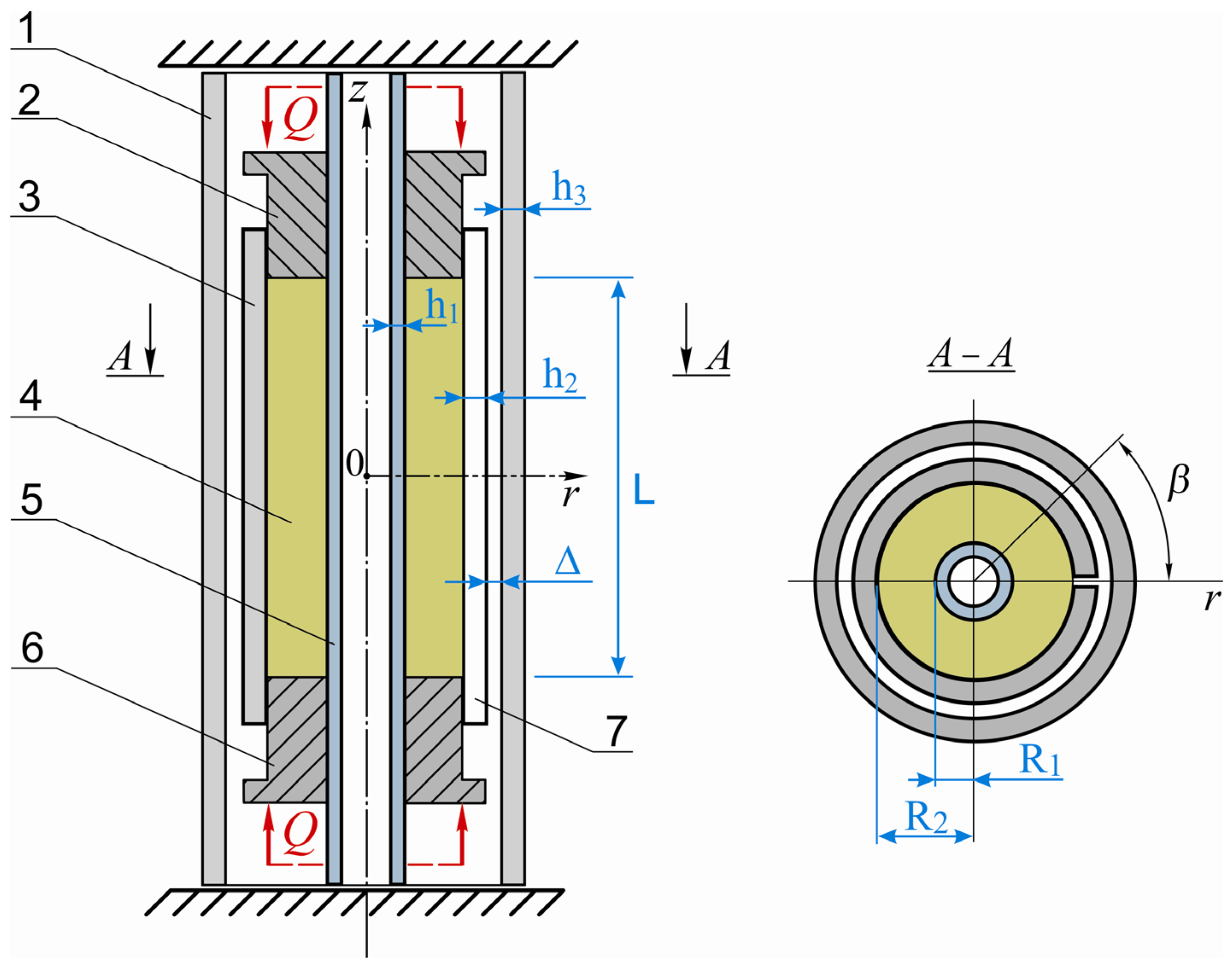
The interaction scheme of the adaptive shell shock absorber components is presented in Figure 2. The deformable filler in the form of a hollow cylinder 4 is placed between two coaxially installed components—an open cylindrical shell 3 outside the filler and an internal shaft 5. The filler has length L, inner and outer radii R1 and R2, respectively. The wall thicknesses of the shaft and shell are denoted as h1 and h2. The external axial load Q is applied to the ends of the filler through annular pistons 2 and 6. The nature of contact interaction in the pairs “filler-shell” and “filler-shaft” is described by Coulomb’s dry friction law. The stress-strain state of the system will be considered in a cylindrical coordinate system taking into account the contact interaction of components. The shell includes a longitudinal construction slit, which increases tangential compliance while preserving axial stiffness. The slit width is set by tolerances and the cutting tool and is typically a few millimeters. Within the considered load range, the slit edges do not come into contact, and therefore contact between them was not modeled.
The boundary conditions on the lateral surfaces of the filler have the form:
σ r ( r = R i ) = σ i ,   τ r ( r = R i ) = τ i , i = 1 , 2 ,
where σ i , τ i are normal and tangential contact stresses; σ r , τ r are normal and tangential stresses in the filler, index i = 1 denotes the contact pair “filler-shaft”, and index i = 2 —“filler-shell”.
The relations of unilateral normal contact in contact pairs have the form:
w i = w i w filler ( i ) = 0 , σ i < 0 , w i = w i w filler ( i ) > 0 , σ i = 0 , z [ L / 2 ; L / 2 ] ,   i = 1 , 2 ,
where w i are jumps of radial displacements; w filler —is the radial displacement of the filler; w i —is the radial displacement of the open shell or shaft.
Let us denote: τ r = ( τ r z , τ r β ) is the tangential stress vector in the contact plane, τ r z , τ r β are axial and tangential components of tangential stress; v = ( v z , v β ) is the vector of relative sliding velocity of contact surfaces, v z , v β are axial and tangential components of sliding velocity. Then the influence of dry friction on the contact surfaces of the filler with the shell and shaft is described as follows. When r = R i , i = 1 , 2 , β ( 0 , 2 π ) ,   z [ L / 2 , 2 π ] , we have:
-
in sliding zones:
v 0 ,   τ r i = f i σ r i v v ;
-
in adhesion zones:
v = 0 ,   τ r i f i σ r i ,
where f i are friction coefficients between the filler and shell and between the filler and shaft on the interface surfaces r = R i .
At both ends of the filler, the conditions are satisfied:
σ z ( ± L / 2 ) = Q π ( R 2 2 R 1 2 ) ,
where σ z are axial stresses in the filler.
We assume that the ends of the shaft and shock absorber housing are rigidly clamped at such a distance from the filler ends that the specific method of fixation does not affect the operation of the elastic element.
When the radial clearance Δ between the open shell and the shock absorber housing is exhausted, a transition to a new phase of elastic element operation occurs. Additional contact interaction is realized between shell 3 and the inner surface of housing 1. Initially, contact occurs locally (point or linear), but with increasing external load, the contact zone gradually expands. This leads to an increase in the overall system stiffness and redistribution of contact forces. If we denote the normal contact stresses on the outer surface of the open shell as σ sh , and its radial displacements as w 2 , then the new contact can be described by the conditions of unilateral interaction (contact alternative):
( Δ w 2 ( z ) ) σ sh ( z ) = 0 ,   Δ w 2 ( z ) 0 ,   σ sh ( z ) 0 .
Thus, after closing the clearance, the system transitions to an adaptive stiffness mode, the rigid housing becomes an additional support element that restrains the deformation of the shell and filler. Further investigation of this mode was performed numerically using a finite element model.
When considering cyclic loading of the drilling shock absorber and constructing damping diagrams, we applied a quasi-static approach, within which inertial components in equilibrium equations are considered insignificant and discarded. In this case, physical time t loses its role as an independent variable, and instead, a loading parameter λ is introduced, which scales the external non-monotonic load Q:
Q ( t ) Q ( λ ) , λ = t T ,
where Q ( λ ) is the external load vector, T is the characteristic period of the loading cycle, which in the quasi-static problem has an auxiliary value as a normalization parameter.
Thus, the solution of the system is found not as a function of time, but as a function of the loading parameter λ , i.e.:
K ( u ( λ ) ) u ( λ ) = Q ( λ ) ,
where K —is a nonlinear stiffness matrix dependent on displacements, u ( λ ) is the displacement vector. Here the parameter λ performs the role of conditional “pseudo-time” and allows tracking the energy behavior of the system during a complete loading-unloading cycle and constructing damping loops without considering time derivatives.

2.3. Finite Element Model of the Device

Within this study, a finite element model of the elastic element of a drilling shock absorber was constructed, corresponding to the size that is most commonly used and most in demand in drilling practice. During modeling, special attention was paid to accurate reproduction of the element geometry, its physical and mechanical characteristics, as well as contact interaction conditions, which ensures maximum proximity of the computational model to real operating conditions. The structural scheme of the elastic element is shown in Figure 2, its main geometric parameters are in Table 1, and physical and mechanical characteristics are below in the text.
The open cylindrical shell of the elastic element is made of 60SiCr7 steel—chrome-silicon structural spring steel (EN grade 61SiCr7; ISO/EN material number 1.7108; EN 10089). The through shaft is made of alloy steel 40 Kh (American equivalent—AISI 5140). Both materials have the same elastic and shear moduli, as well as Poisson’s ratio, but differ in yield strength. For the shell, the following physical and mechanical characteristics are adopted: yield strength—1400 MPa, Young’s modulus—210 GPa, shear modulus—80 GPa, Poisson’s ratio—0.31. For the shaft, the yield strength is 700 MPa.
The filler material is raw rubber with increased oil and gasoline resistance. For it, the following are adopted: elastic modulus—E = 10 MPa, shear modulus—G = 3.33 MPa, Poisson’s ratio—0.49.
The contact interaction between the filler and shell, as well as between the filler and shaft, is described by the dry friction law. In calculations, a friction coefficient of 0.2 was used for both contact pairs. The range of external load applied to the pusher is 0–200 kN.
Construction of finite element models was performed in ANSYS Workbench 2022R1 environment using modules for geometric modeling, computational mesh generation, and contact mechanical analysis. All device components were modeled separately with subsequent determination of contact pairs and application of load in assembled form. All model materials were considered linearly elastic, while the nonlinearity of the system as a whole is due to contact interaction of bodies, presence of dry friction effects, and adaptive stiffness change due to the presence of initial clearance between the shell and housing.
After a series of trial virtual tests, the configuration of the finite element model was unified. All deformable components—open shell, weakly compressible filler, and steel shaft were discretized with hexahedral finite elements. The transition to a unified hexahedral topology was performed to improve the quality of modeling contact interaction with friction between the filler and shell and between the filler and shaft. Face-to-face alignment on contact surfaces reduced numerical penetration, improved the stability of the Coulomb condition solver, and increased the reproducibility of shear stresses in the contact zone.
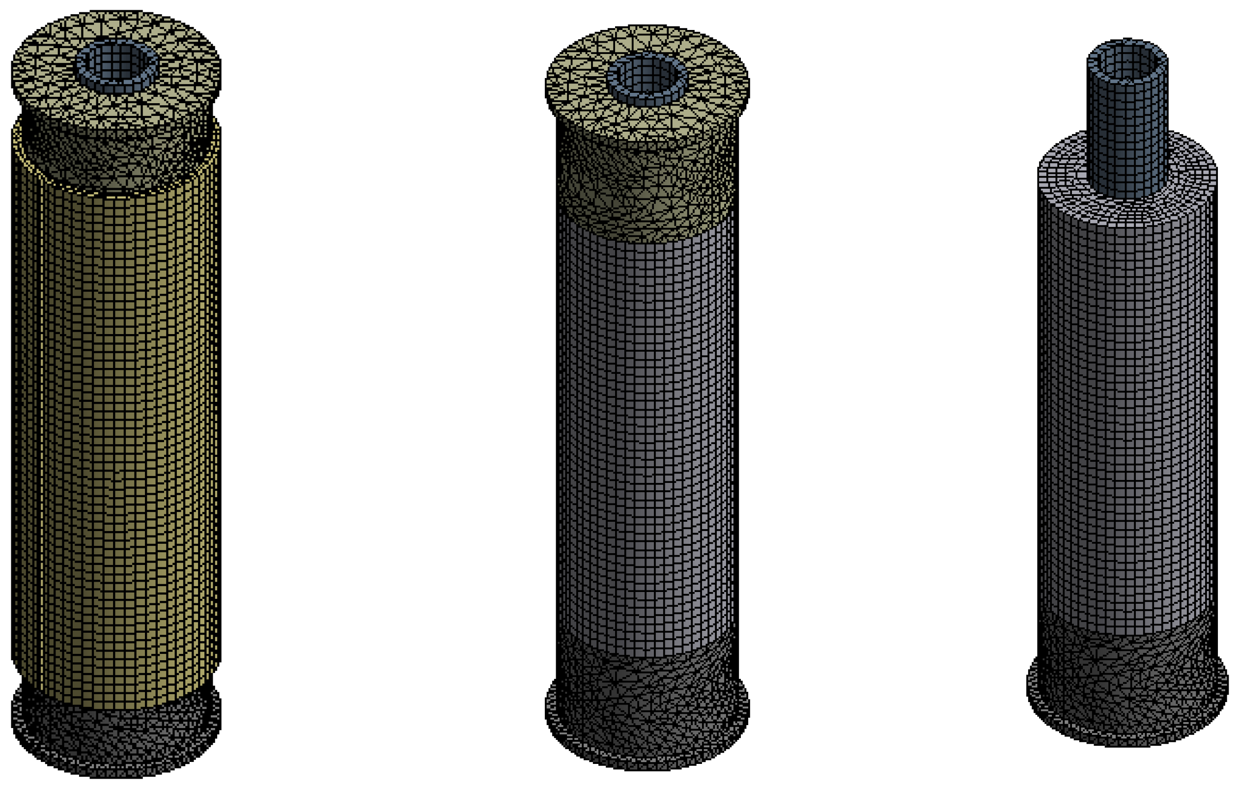
For the open shell, a multi-zone approach was applied to form a hexahedral mesh with controlled element alignment along the cut line and through thickness; for the filler and shaft–regular “sweep and structured” partitioning with quality control (aspect ratio, twist angle, transition smoothness). Since the annular pistons and shock absorber housing were considered as absolutely rigid bodies, automatic mesh generation selected by the software was applied to them. The accuracy of calculations was verified by convergence analysis, i.e., discretization was gradually refined until stabilization of von Mises equivalent stresses in control zones. Convergence criterion—relative change of results no more than 5% between successive mesh variants. Figure 3 presents the general view of the finite element model of the shell elastic element (shock absorber housing not shown).
Special attention was paid to describing the contact interaction between the shell and filler, as well as between the filler and shaft. A nonlinear model with dry friction (Frictional contact) was applied to both contact pairs. The same friction coefficient of 0.2 was used for both contact pairs. The Augmented Lagrange method was used in the contact problem formulation, which provides an effective combination of accuracy and stability in cases of complex interaction of bodies with adhesion and sliding [60,61,62]. The tolerance for penetration of contact surfaces was set at 0.0015 mm. Normal contact stiffness was determined automatically (Program Controlled), which allowed avoiding overestimation of stiffness characteristics and ensuring stable convergence of solution iterations [63,64,65].

3. Results

3.1. Operation of the Shock Absorber in Normal Loading Mode (With Unclosed Radial Clearance)
The radial clearance between the open shell of the elastic element and the shock absorber housing does not close in the working range of loads. Its value was selected based on the following considerations: fitting all parts into the dimension of limited mounting space; operation of the elastic element with unclosed clearance at maximum loads allowable for PDC drill bits; limiting the degree of utilization of the bearing capacity of the open shell—no more than 60%.
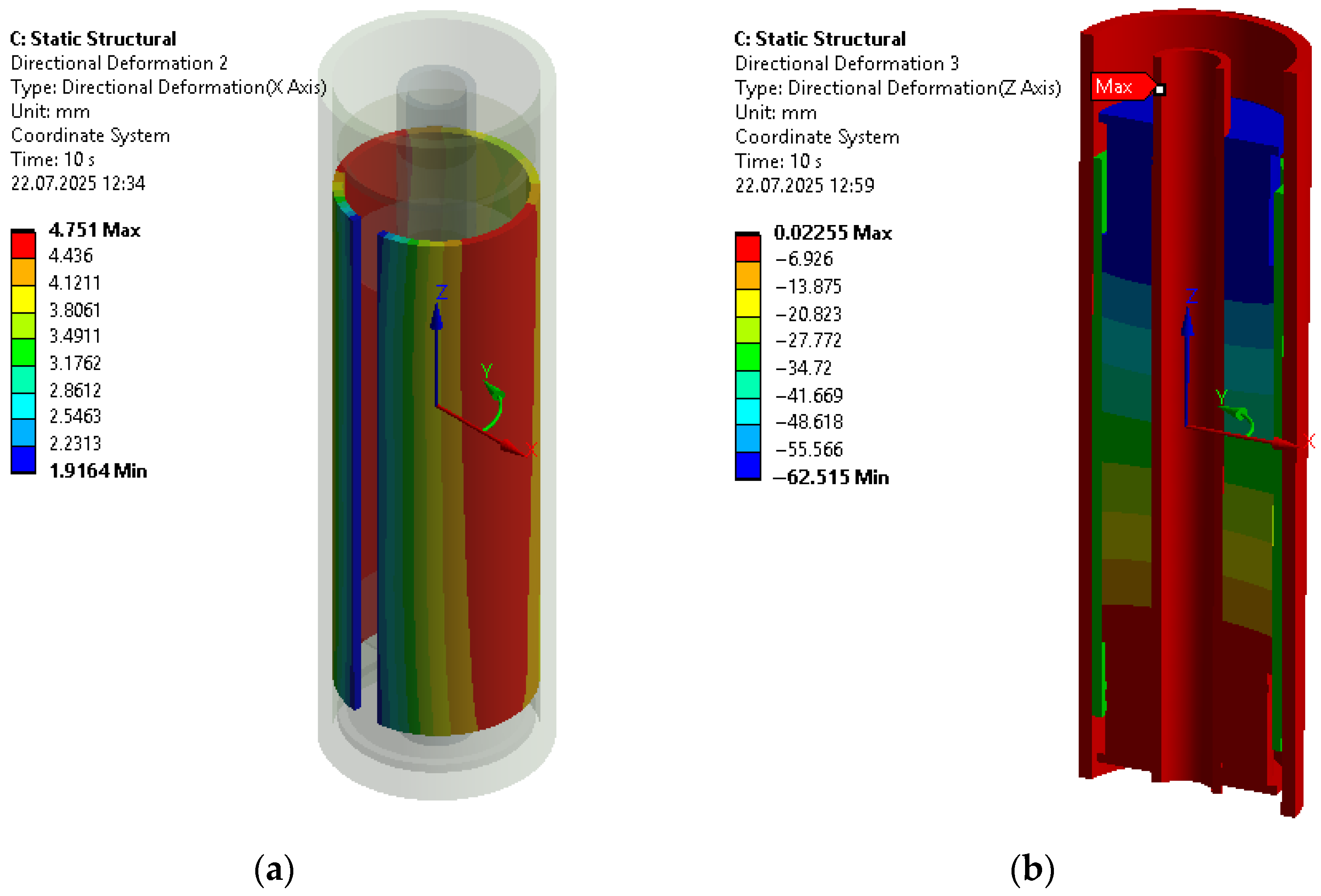
Figure 4a presents a cartogram of radial displacements of the open shell under piston loading of 95 kN (these displacements are directed along the X axis of the cylindrical coordinate system). The deformation pattern is non-axisymmetric, in particular, minimum radial displacements are observed in the cut zone, and maximum—at azimuth approximately β ≈ 90° (β is counted from the middle of the cut gap). The recorded maximum radial displacement is 4.75 mm. Isofields along the shell length reveal moderate non-uniformity of radial displacements caused by friction in contact pairs. Additional studies show that with increasing friction coefficient in the “filler-shell” and “filler-shaft” pairs, the adhesion zone in contact pairs increases, and gradients of radial displacements near the ends increase. The ‘Time’ label in the ANSYS post-processor denotes the index/end of a load step in a quasi-static analysis and is not physical time. The normalized parameter t/T in the manuscript specifies the loading-cycle phase for which the results are presented.
Figure 4b shows axial (directed along the Z axis) displacements under the same conditions. The lower piston of the elastic element is fixed, and the load is applied to the upper piston. Therefore, the displacement of the lower piston approaches zero, while the upper piston has an absolute displacement of 62.5 mm. Due to the entry of both pistons into the shell, there is a component of rigid-body motion of the shell in the axial direction. At the same time, an increase in friction coefficients in contact pairs reduces the proportion of sliding along the contact and reduces the total piston stroke at fixed load. Recall that in Figure 4b, to suppress rigid-body modes and ensure kinematic stability of the finite-element model, the lower piston is fixed. At the illustrated phase, the upper piston moves inward while the shell advances over the fixed lower piston. This produces effectively symmetric boundary kinematics and a near-symmetric axial displacement field.
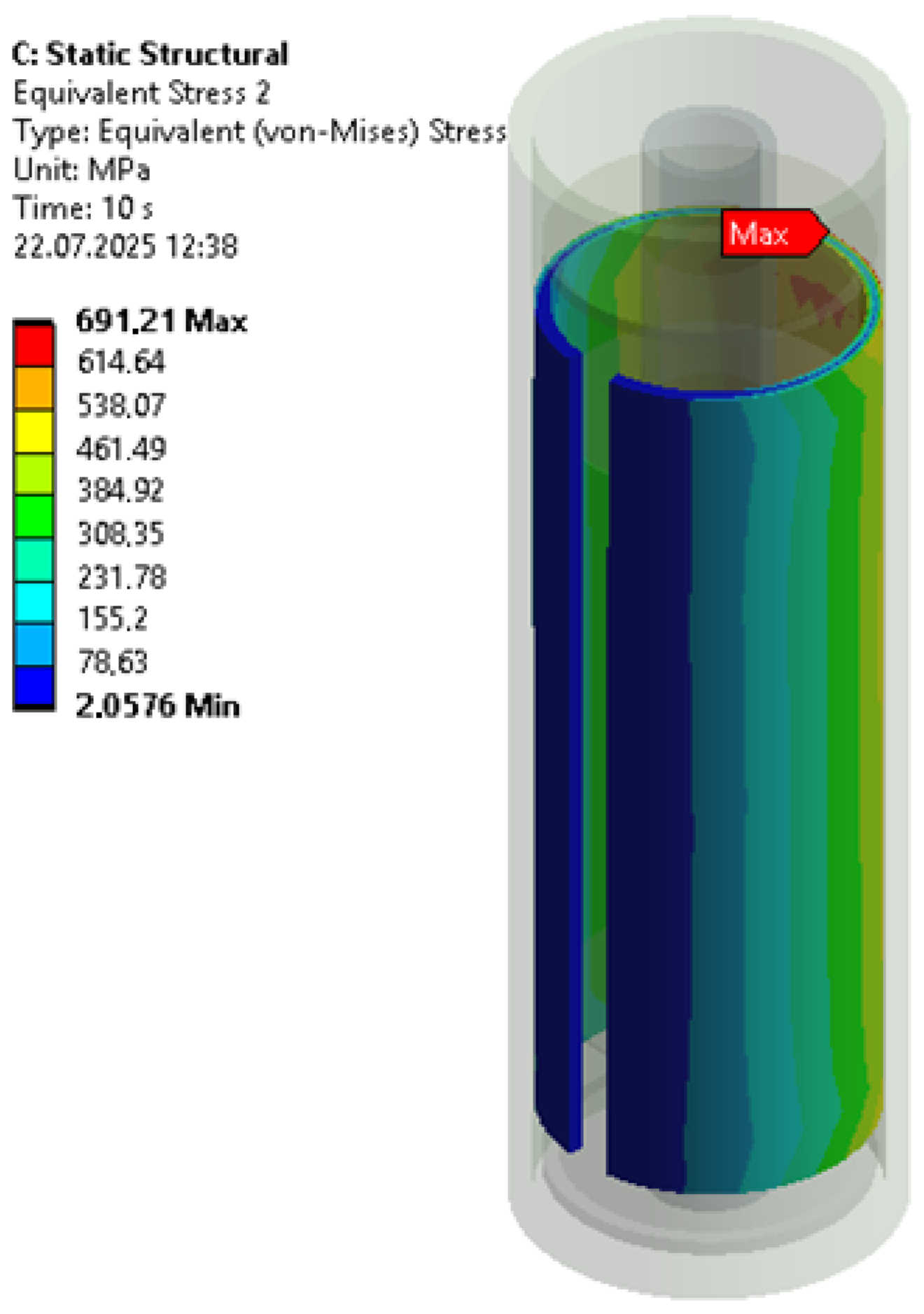
According to Figure 5, maximum von Mises equivalent stresses are localized on the opposite side from the cut of the shell (at azimuth value β ≈ 180°), concentrating in the collar zones near the ends. Under piston loading of 95 kN, maximum equivalent stresses of 691 MPa were obtained. For a shell made of 60SiCr7 steel (yield strength 1400 MPa), this corresponds to a safety factor of ~2.0, which agrees with the design criterion.
Let us analyze the structural hysteresis that occurs in the shell elastic element in response to external non-monotonic loading. In other words, it is necessary to construct a deformation diagram. It, taking into account the known loading history of the elastic element, allows predicting the behavior of the considered non-conservative system at any moment after the beginning of the loading process. Such a diagram is also useful for estimating the amount of energy dissipated during the loading-unloading cycle. The process of non-monotonic loading of the damper was investigated in a quasi-static approximation.
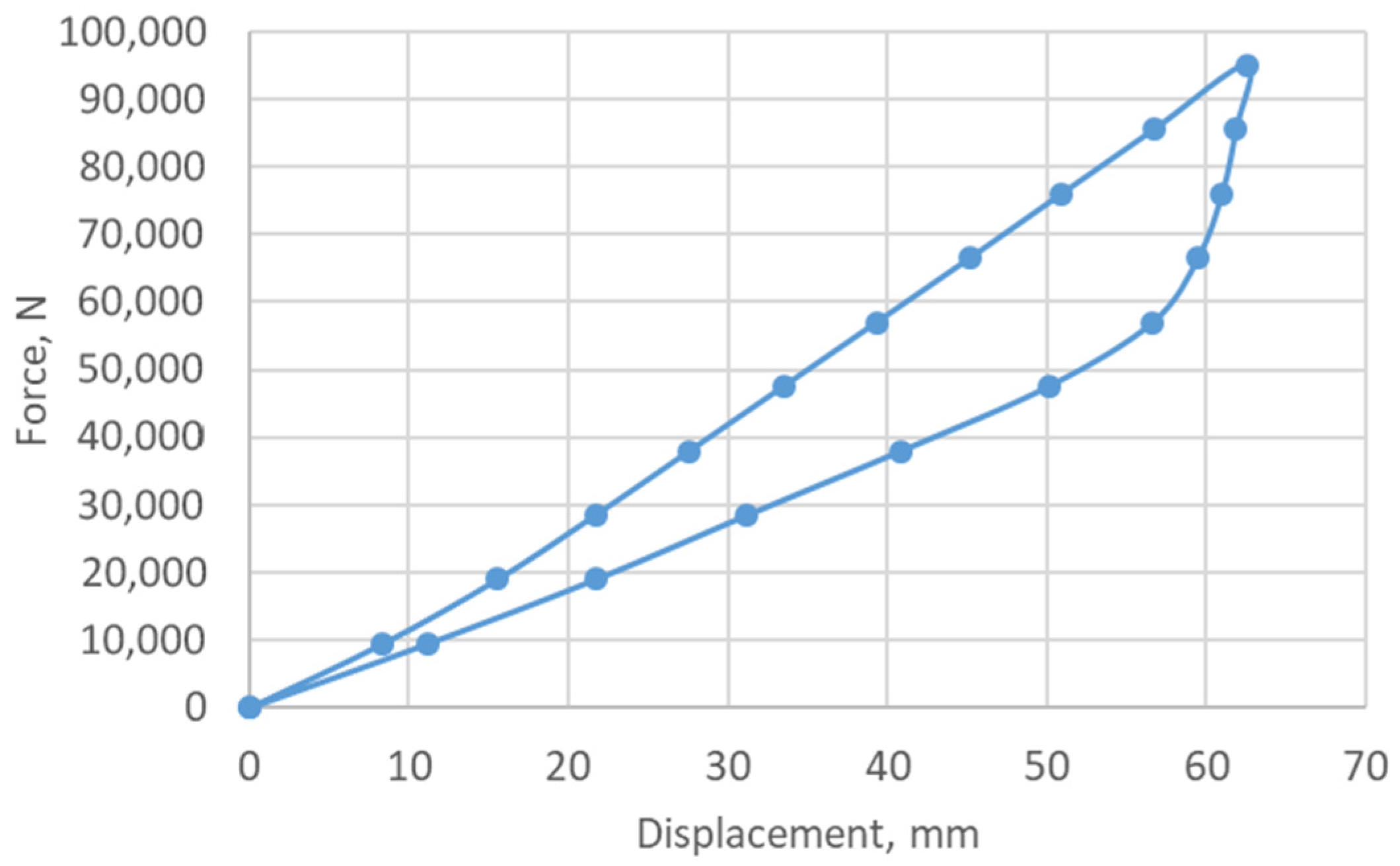
For analysis of results, the usual color visualization of friction damper displacements offered by the ANSYS postprocessor proved insufficiently informative. Therefore, to construct the “force-deformation” diagram, we divided the loading range and unloading range into twenty intervals. At the boundaries of each loading or unloading interval, the problem solution results were recorded. These data were used to construct the diagram (Figure 6). The abscissa shows deformations (settlement) of the damper. The ordinate shows the force value applied to the upper piston. On the diagram of piston settlement dependence on force, a hysteresis loop was formed. Figure 6 shows that during loading, the upper curve initially has a nonlinear character, and then transitions to a straight line. During unloading, the lower curve does not repeat the loading trajectory. Due to the presence of friction forces, the system retains certain residual deformation even when the load decreases, and this creates a hysteresis effect. The area of the constructed loop is numerically equal to the energy losses dissipated by the elastic element during one loading-unloading cycle.
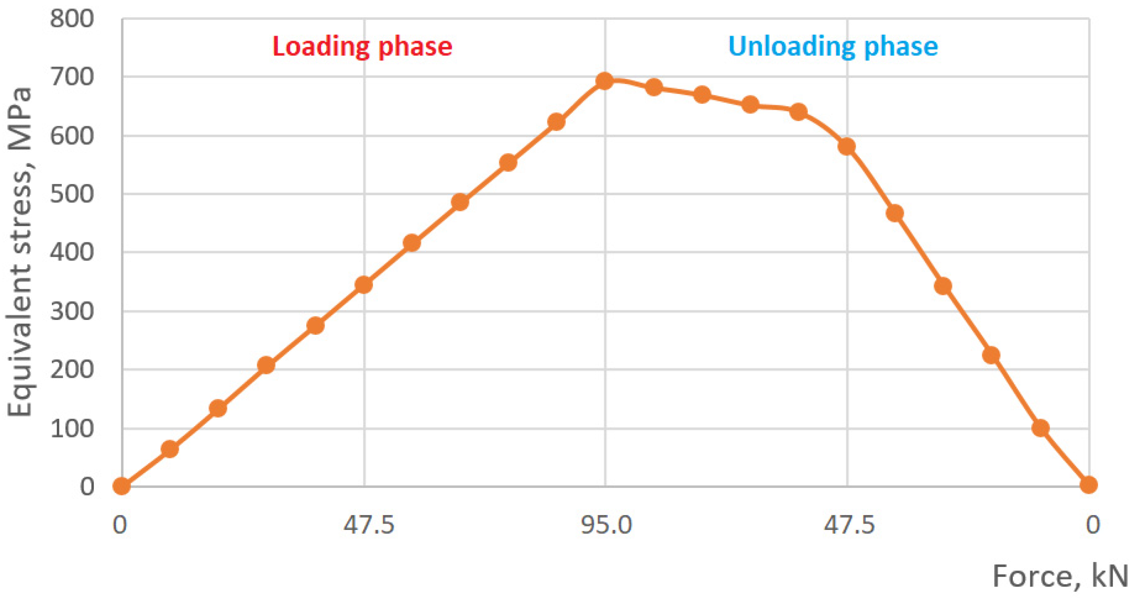
Figure 7 presents the dependence of maximum equivalent stresses on external load. For a zero-to-peak cycle, in which the load varied from 0 to 95 kN and again to 0, discretization of the range into twenty equal intervals was performed. At each control point of this cycle, the maximum value of equivalent stress according to the von Mises criterion in the wall of the open shell was determined. Based on the obtained data, a graph was constructed reflecting the evolution of the shell stress state throughout the entire loading and unloading process, which allows evaluating both peak values and the nature of their changes during the cycle. Such a graph allows directly comparing loading and unloading phases, identifying differences between them, and evaluating the presence of hysteresis in the change of equivalent stresses.
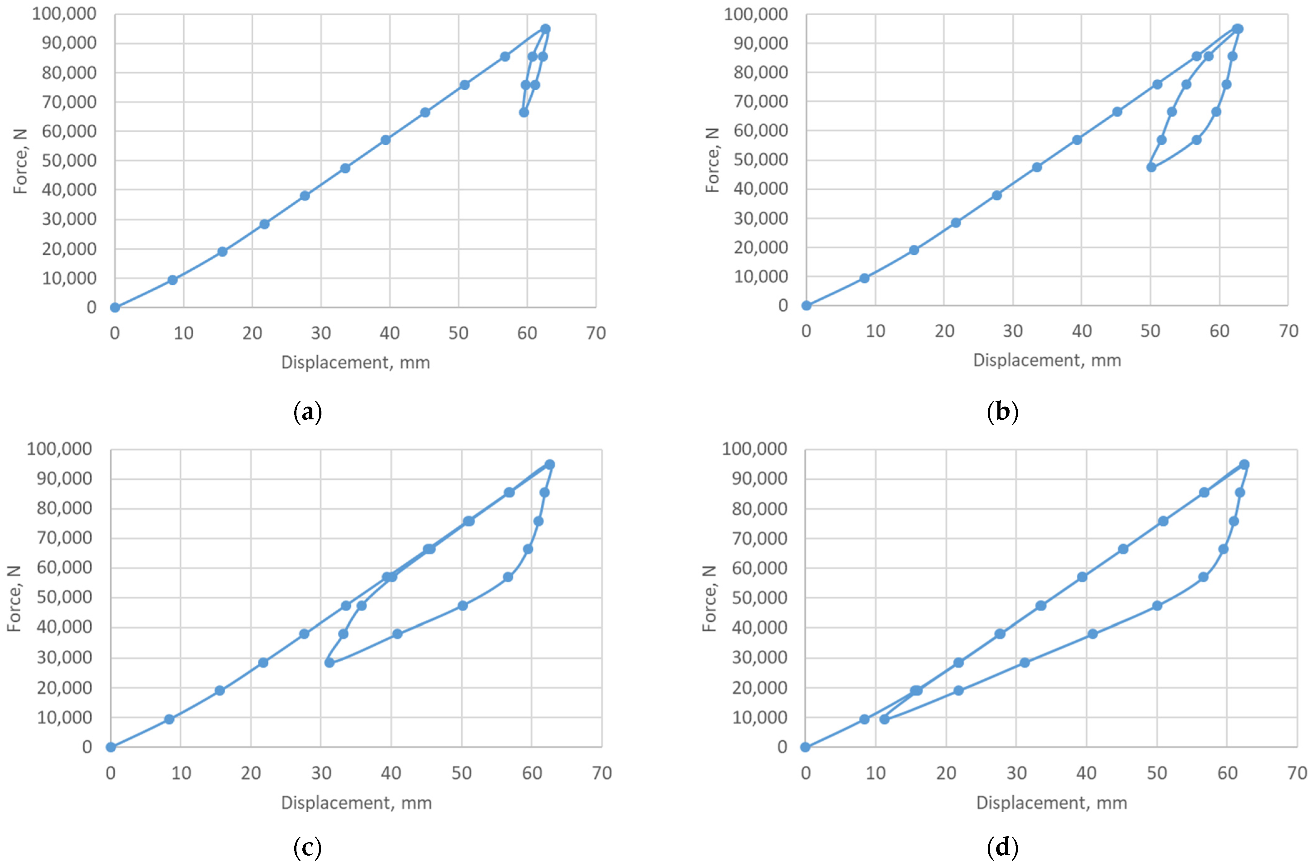
The change in hysteresis loop shape reflects the change in mechanical behavior of the elastic element under load. In particular, asymmetry or shift of the loop indicates a change in friction conditions, appearance of residual deformations, or material degradation, which directly signals a change in the effectiveness of the shock absorber operation. Figure 6 showed the basic hysteresis loop constructed for a zero-to-peak cycle when the minimum load was 0 kN and the maximum was 95 kN. Such a cycle allows evaluating the full amplitude of elastic element deformation and the maximum level of energy absorption. Further, to investigate the influence of cycle asymmetry, hysteresis loops were constructed (Figure 8) at four values of the asymmetry coefficient:
0.7—load varies from 66.5 to 95 kN (Figure 8a);
0.5—load varies from 47.5 to 95 kN (Figure 8b);
0.3—load varies from 28.5 to 95 kN (Figure 8c);
0.1—load varies from 9.5 to 95 kN (Figure 8d).
Figure 8. Dependence of elastic element hysteresis loop on cycle asymmetry coefficient: (a)—0.7; (b)—0.5; (c)—0.3; (d)—0.1.
Vibration 08 00060 g008
As the asymmetry coefficient decreases, the cycle amplitude increases, which leads to widening of the hysteresis loop and increase in its area. This means greater energy losses per cycle, i.e., higher damping efficiency. At high asymmetry coefficients, the loop becomes narrower, indicating reduced energy absorption and greater contribution of the elastic response component.
A peculiarity is observed at asymmetry coefficients of 0.3 and less. In these cases, the reloading curve initially differs from the branch of initial (active) loading, but after passing a certain section, they coincide. This indicates that at the beginning of reloading, local adhesion areas still exist in friction pairs, but further all contact surfaces transition to a steady sliding mode. Friction conditions stabilize, and the mechanical response of the system completely repeats the previous one without additional irreversible deformations in the investigated load range.

3.2. Adaptive Behavior of the Shock Absorber in Emergency Mode (Radial Clearance Closure)

With increasing load on the piston, the shell transitions from free deformation mode to active interaction with the housing. This process is accompanied by a qualitative change in the spatial distribution of contact and equivalent stresses, indicating adaptive restructuring of the element’s mechanical operation.
Analysis of contact stress cartograms (Figure 9) shows that at a load of 130 kN, the zone of intense contact is localized mainly in sectors with azimuths of 90° and 270°—diametrically opposite to each other. In these areas, contact pressure values reach maximum, while on the rest of the inner surface of the shell, contact is absent or has a low level. Initial contact zones have limited circumferential extent and gradually “spread” in both directions from the maximum point. When the load increases to 200 kN, contact pressure is already distributed over almost the entire inner surface of the shell. At the same time, peak values change insignificantly, but the area participating in load transmission sharply increases. Such behavior indicates a system transition from localized to more uniform contact, which reduces local overloads and ensures more effective load distribution.
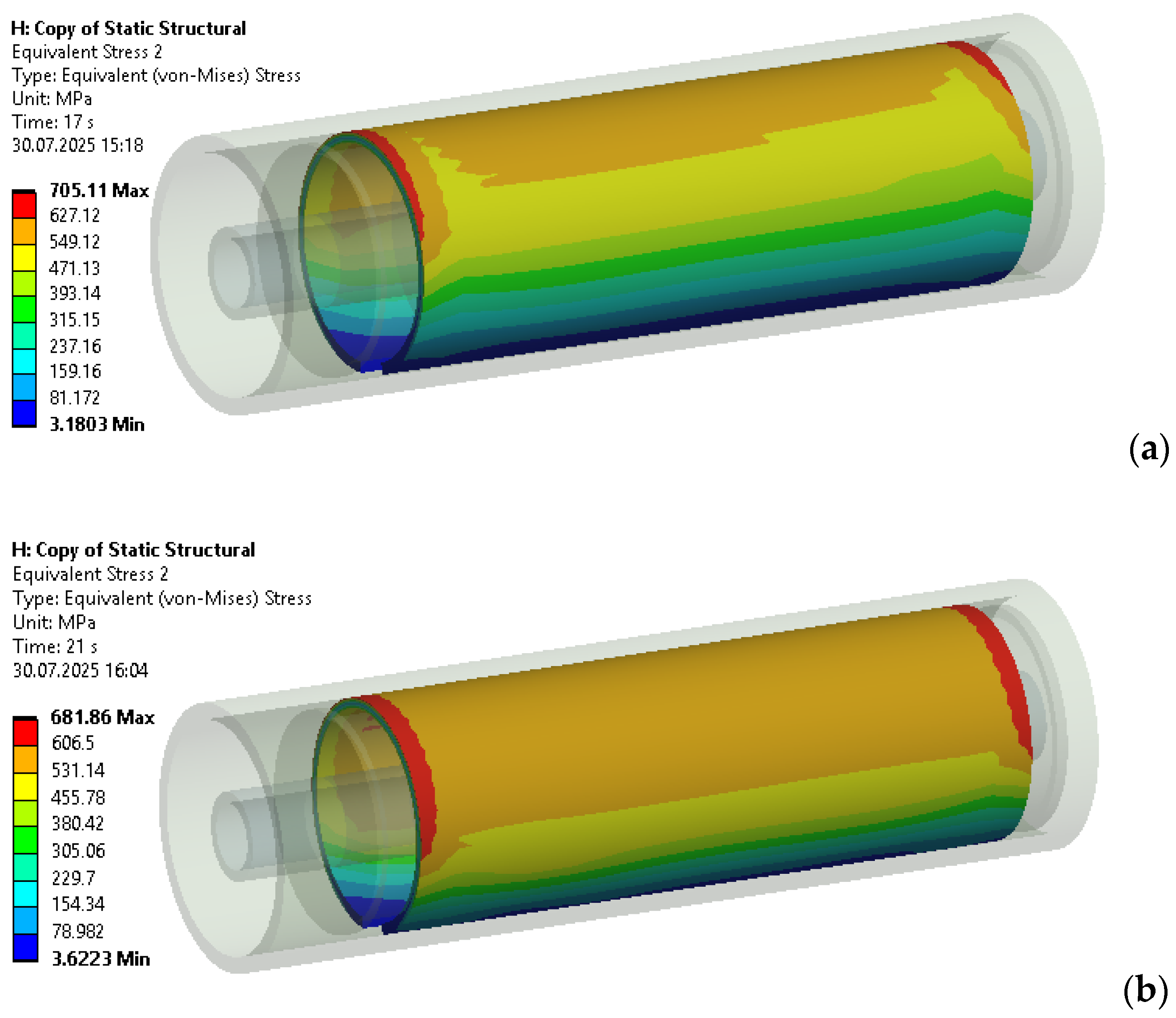
The distribution of equivalent stresses in the shell material (Figure 10) demonstrates a similar pattern. At an external load of 130 kN, maximum stress values act within a narrow band in the sector located opposite the cut (Figure 10a). Their action is limited to a small area, and the peak value reaches 705 MPa.
When the load increases to 200 kN, maximum stress values decrease (to 681 MPa), but the area with increased stresses significantly expands, covering most of the shell. This decrease in peak values with simultaneous increase in loaded area indicates force redistribution over a wider contact zone, which reduces stress concentration and potentially increases the service life of the elastic element.
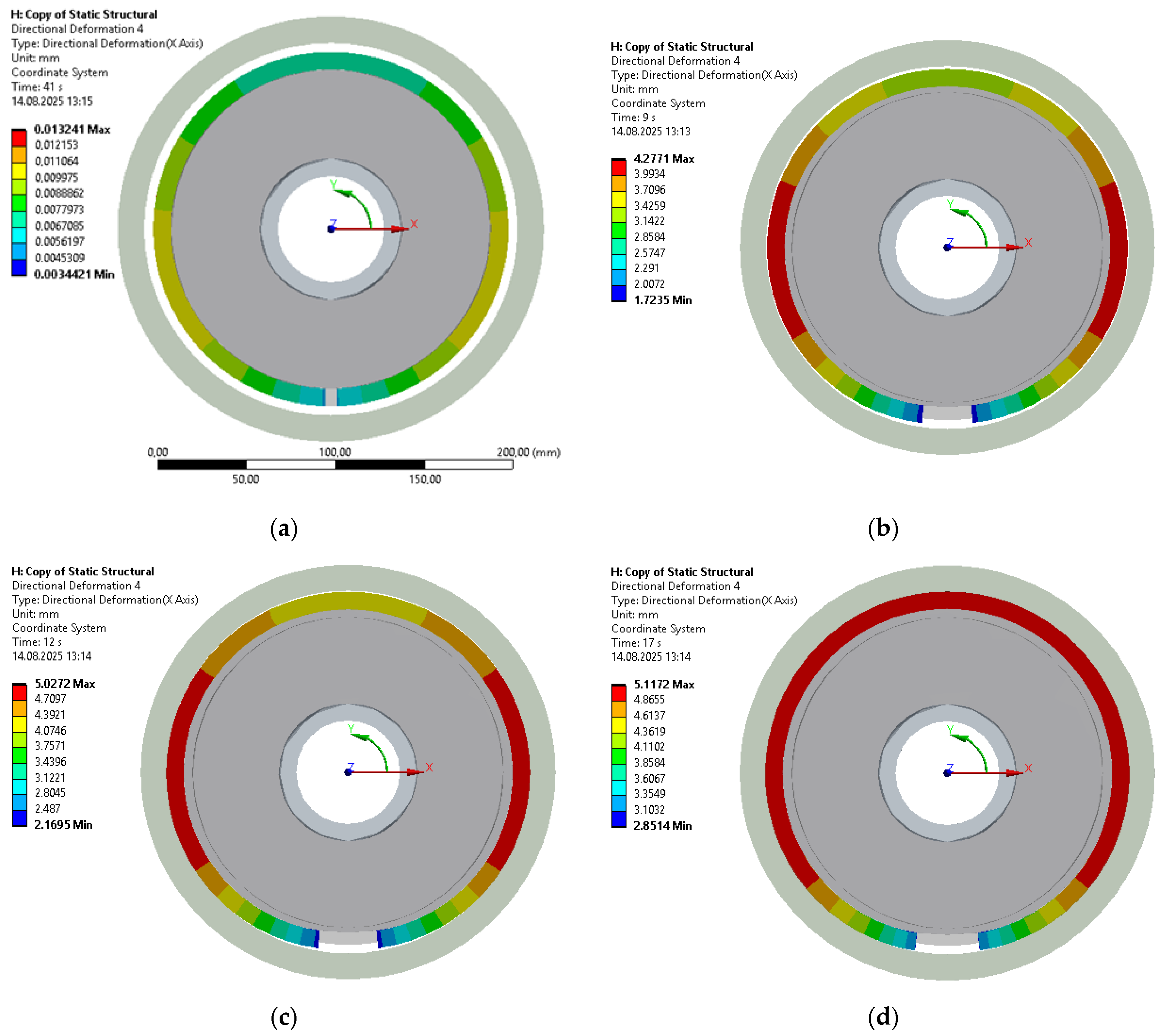
The sequence of radial clearance closure additionally confirms this adaptive behavior (Figure 11). At a load of 90 kN, the clearance is still fully open. At 100 kN, it closes only in sectors with azimuths of 90° and 270°, while other areas remain without contact. Further increase in load to 200 kN leads to almost complete closure of the clearance, except for small zones near the edges of the shell cut, where contact has not yet been established. Thus, the contact process begins from local areas of maximum approach, after which the contact zone gradually expands, forming more uniform contact interaction around the shell perimeter.
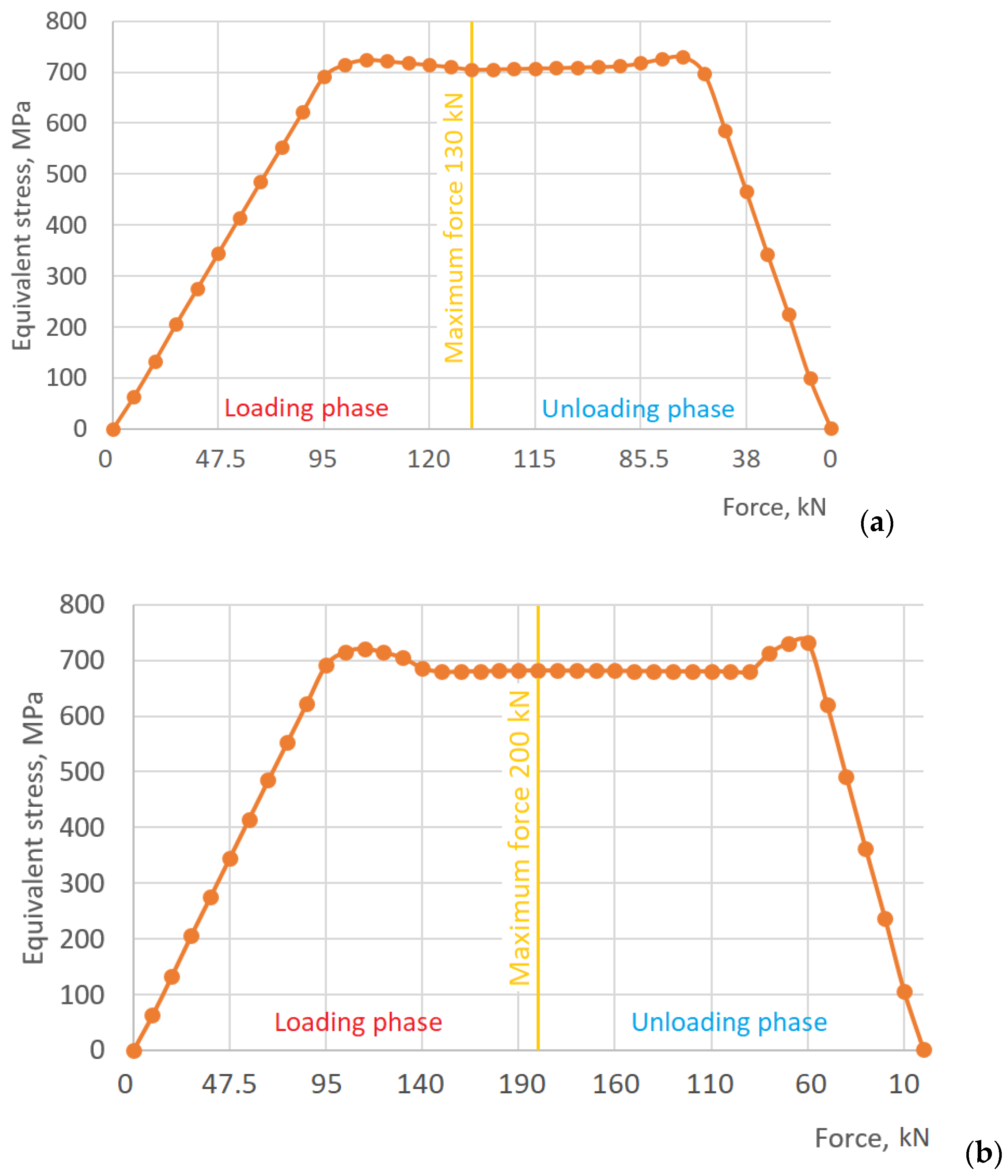
To analyze the influence of radial clearance closure on shock absorber characteristics, deformation diagrams were constructed for two zero-to-peak loading cycles: 0–130–0 kN and 0–200–0 kN (Figure 12). As before, loading and unloading were divided into intervals, and force and settlement values were recorded at the boundaries of each. Since we sought to investigate in more detail the features of the damping loop in the loading-unloading range when the external force exceeds 95 kN, this section of the loop was additionally divided into smaller intervals. In the first case (0–130–0 kN), the hysteresis loop reflects the element operation with partial clearance closure, i.e., the active contact zone between the shell and housing is localized (Figure 12a). In the second case (0–200–0 kN), the deformation curve corresponds to the mode of complete clearance closure—contact pressure is distributed over almost the entire shell surface, which leads to an increase in loop area and increase in energy dissipated during the cycle (Figure 12b). On both graphs, a characteristic feature is observed when the external force reaches a value of about 100 kN, the loading branch noticeably steepens, indicating an increase in elastic element stiffness due to gradual closure of the radial clearance.
Additionally, for both zero-to-peak cycles, graphs of maximum equivalent stress changes in the open shell throughout the entire loading and unloading process were constructed. In the case of the 0–130–0 kN cycle, the equivalent stress at Q = 130 kN reaches 705 MPa (Figure 13a). In the case of the 0–200–0 kN cycle, the equivalent stress at Q = 200 kN reaches 681 MPa (Figure 13b). The decrease in equivalent stress value in the second case is explained by the fact that after complete clearance closure, contact pressure is distributed more uniformly over the shell surface, and the zone of concentrated stresses expands, reducing local peaks. Also, on both graphs, increases in maximum equivalent stresses are observed during clearance closure and opening. Note that, in both plots, the loading and unloading branches of the equivalent-stress response differ. This discrepancy reflects mechanical hysteresis in the shell-type damper arising from dry frictional contact.
Thus, the obtained results provide grounds to consider the investigated shock absorber as an element with pronounced adaptive properties. Under normal operating conditions, when external loads are in the nominal range and the radial clearance remains open, the shell deforms without contact with the housing, providing high system compliance. If an emergency situation occurs during deep drilling and the load amplitude increases significantly, the shell closes the clearance and begins to contact the housing. This allows redistributing the load, reducing peak stresses, and safely absorbing overloads. When external conditions stabilize again, the shell returns to its initial state with open clearance, restoring the normal operating mode of the shock absorber.

4. Conclusions

This work has constructed a numerical model of a shell elastic element of a drilling shock absorber that for the first time takes into account local contact of the open shell with the housing after exhaustion of the radial clearance. This made it possible to reproduce the transition to adaptive stiffness mode and quantitatively evaluate the energy absorption properties of the system under different loading scenarios.
Normal mode (clearance open). In this regime, the elastic element exhibits high compliance; the open shell deforms without contacting the housing, and vibration energy is partially dissipated by friction at the filler–shell and filler–shaft interfaces. The spatial pattern of displacements and stresses is non-axisymmetric due to the presence of the cut, and hysteresis in this mode has a basic form characteristic of the combination of elastic response with dry friction. When the loading cycle asymmetry coefficient decreases, the hysteresis loop area increases, i.e., energy dissipation per cycle increases. For asymmetry coefficients less than 0.3, during reloading, a return of the diagram branch to the trajectory of initial (active) loading is observed, which corresponds to the removal of local adhesion zones and transition of contacts to steady sliding mode.
Adaptive phase (clearance closure). Upon reaching a certain threshold load, the shell locally touches the inner surface of the housing. Primary contact zones arise in diametrically opposite sectors of the shell with azimuths of 90 and 270 degrees. On the “force-settlement” diagram, this manifests as “steepening” of the loading branch, i.e., the effective stiffness of the elastic element increases, and the load begins to redistribute to additional support—the housing. With further increase in external load, contact with the housing spreads to most of the shell surface, i.e., this contact pair transitions from local to more uniform contact.
The kinematics of clearance closure is a sequential process that begins with local “spots” of contact on local areas of the shell surface and then spreads circumferentially and along the axis. Primary contact zones arise in sectors with azimuths of 90° and 270° (counted from the middle of the cut gap), where radial displacements of the shell are greatest. As a result, the shell transitions from a compliant state to a state where it rests on the housing, which is accompanied by redistribution of contact pressure and reduction of maximum equivalent stresses. During unloading of the elastic element, clearance opening occurs in reverse sequence with characteristic hysteresis.
These findings are derived from a quasi-static finite-element model with Coulomb friction; dynamic inertial effects, possible rate dependence of friction, and wear are outside the present scope and will be examined in further studies.
In the next phase of this research, the authors plan to conduct bench tests of the adaptive shell-type damper.

Author Contributions

Conceptualization, A.V.; methodology, A.V., V.M. and A.A.; software, V.M.; validation, A.V. and V.M.; formal analysis, A.A.; investigation, A.V.; resources, V.M.; data curation, A.V., V.M. and A.A.; writing—original draft preparation, A.V.; writing—review and editing, A.V. and V.M.; visualization, A.V. and A.A.; supervision, V.M. and A.A.; project administration, A.V.; funding acquisition, A.V. All authors have read and agreed to the published version of the manuscript.

Funding

This research received no targeted external funding.

Data Availability Statement

The data are contained within this article.

Conflicts of Interest

The authors declare no conflict of interest.

References

  1. Xu, Y.; Zhang, H.; Guan, Z. Dynamic Characteristics of Downhole Bit Load and Analysis of Conversion Efficiency of Drill String Vibration Energy. Energies 2021, 14, 229. [Google Scholar] [CrossRef]
  2. Cveticanin, L.; Kraljevic, S.; Cverticanin, D. Review on dynamic models of drilling systems applied in oil and gas industry. Acta Mech. 2023, 234, 4427–4442. [Google Scholar] [CrossRef]
  3. Wang, R.; Liu, X.; Song, G.; Zhou, S. Non-Linear Dynamic Analysis of Drill String System with Fluid-Structure Interaction. Appl. Sci. 2021, 11, 9047. [Google Scholar] [CrossRef]
  4. Bembenek, M.; Grydzhuk, Y.; Gajdzik, B.; Ropyak, L.; Pashechko, M.; Slabyi, O.; Al-Tanakchi, A.; Pryhorovska, T. An Analytical–Numerical Model for Determining “Drill String–Wellbore” Frictional Interaction Forces. Energies 2024, 17, 301. [Google Scholar] [CrossRef]
  5. Chen, C.; Bi, C.; Ji, G.; Wang, H.; Huo, Y.; Yu, P. Research on Vibration Reduction, Energy Enhancement, and Speed Increase Methods for Drilling String in Deep Heterogeneous Strata. Processes 2024, 12, 2645. [Google Scholar] [CrossRef]
  6. Sui, D.; Aadnøy, B.S. Rate of Penetration Estimation with Parameter Correction. Appl. Sci. 2025, 15, 4650. [Google Scholar] [CrossRef]
  7. Li, J.; Peng, J.; Ge, D.; Zhang, G. Simulation and Experimental Research on a Fluidic Oscillator with a Deflector Structure. Energies 2025, 18, 1336. [Google Scholar] [CrossRef]
  8. Akl, W.; Alsupie, H.; Sassi, S.; Baz, A.M. Vibration of Periodic Drill-Strings with Local Sources of Resonance. Vibration 2021, 4, 586–601. [Google Scholar] [CrossRef]
  9. Aarsnes, U.J.F.; van de Wouw, N. Effect of shock subs on self-excited vibrations in drilling systems. J. Pet. Sci. Eng. 2019, 181, 106217. [Google Scholar] [CrossRef]
  10. Landar, S.; Velychkovych, A.; Mykhailiuk, V. Numerical and analytical models of the mechanism of torque and axial load transmission in a shock absorber for drilling oil, gas and geothermal wells. Eng. Solid Mech. 2024, 12, 207–220. [Google Scholar] [CrossRef]
  11. Abu Seer, T.; Vahdati, N.; Shiryayev, O. Adaptive Torsional Tuned Vibration Absorber for Rotary Equipment. Vibration 2019, 2, 116–134. [Google Scholar] [CrossRef]
  12. Velichkovich, A.S. Design features of shell springs for drilling dampers. Chem. Pet. Eng. 2007, 43, 458–461. [Google Scholar] [CrossRef]
  13. Kulke, V.; Thunich, P.; Schiefer, F.; Ostermeyer, G.-P. A Method for the Design and Optimization of Nonlinear Tuned Damping Concepts to Mitigate Self-Excited Drill String Vibrations Using Multiple Scales Lindstedt-Poincaré. Appl. Sci. 2021, 11, 1559. [Google Scholar] [CrossRef]
  14. Zribi, F.; Sidhom, L.; Gharib, M. Stick–Slip Suppression in Drill String Systems Using a Novel Adaptive Sliding Mode Control Approach. Vibration 2024, 7, 479–502. [Google Scholar] [CrossRef]
  15. Al Shekaili, A.; Afebu, K.O.; Liu, Y.; Papatheou, E. Experimental analysis of drillstring vibrations using a small-scale drilling rig. Nonlinear Dyn. 2025, 113, 17491–17518. [Google Scholar] [CrossRef]
  16. Landar, S.; Velychkovych, A.; Ropyak, L.; Andrusyak, A. A Method for Applying the Use of a Smart 4 Controller for the Assessment of Drill String Bottom-Part Vibrations and Shock Loads. Vibration 2024, 7, 802–828. [Google Scholar] [CrossRef]
  17. Boukredera, F.S.; Hadjadj, A.; Youcefi, M.R. Drilling vibrations diagnostic through drilling data analyses and visualization in real time application. Earth Sci. Inform. 2021, 14, 1919–1936. [Google Scholar] [CrossRef]
  18. Ivan, S.; Andrii, V. Analytical Model of Structural Damping in Friction Module of Shell Shock Absorber Connected to Spring. Shock Vib. 2023, 4140583, 17. [Google Scholar] [CrossRef]
  19. Velychkovych, A.; Mykhailiuk, V.; Andrusyak, A. Numerical Model for Studying the Properties of a New Friction Damper Developed Based on the Shell with a Helical Cut. Appl. Mech. 2025, 6, 1. [Google Scholar] [CrossRef]
  20. Donmez, A.; Cigeroglu, E.; Ozgen, G.O. An Improved Quasi-Zero Stiffness Vibration Isolation System Utilizing Dry Friction Damping. Nonlinear Dyn. 2020, 101, 107–121. [Google Scholar] [CrossRef]
  21. He, S.; Zhang, W.; Li, Z. Application of Dry Friction Contact in Vibration Reduction in Engineering—A Short Review. Coatings 2023, 13, 910. [Google Scholar] [CrossRef]
  22. Huang, Z.; Tan, J.; Liu, C.; Lu, X. Dynamic characteristics of a segmented supercritical driveline with flexible couplings and dry friction dampers. Symmetry 2021, 13, 281. [Google Scholar] [CrossRef]
  23. Pesek, L.; Pust, L.; Snabl, P.; Bula, V.; Hajzman, M.; Byrtus, M. Dry-friction damping in vibrating systems, theory and application to the bladed disc assembly. In Nonlinear Structural Dynamics and Damping; Jauregui, J., Ed.; Mechanisms and Machine Science; Springer: Cham, Switzerland, 2019; Volume 69. [Google Scholar] [CrossRef]
  24. Wahad, H.S.; Tudor, A.; Vlase, M.; Cerbu, N.; Subhi, K.A. The effect of friction in coulombian damper. IOP Conf. Ser. Mater. Sci. Eng. 2017, 174, 012021. [Google Scholar] [CrossRef]
  25. Jaisee, S.; Yue, F.; Hao Ooi, Y. A state-of-the-art review on passive friction dampers and their applications. Eng. Struct. 2021, 235, 112022. [Google Scholar] [CrossRef]
  26. Melatti, V.; D’Ayala, D. Methodology for the assessment and refinement of friction-based dissipative devices. Eng. Struct. 2021, 229, 111666. [Google Scholar] [CrossRef]
  27. Gao, S.; Wang, Y. An evaluation method for dry friction damping of ring damper in gas turbine engines under axial vibration. Aerospace 2021, 8, 302. [Google Scholar] [CrossRef]
  28. Duriagina, Z.A.; Kulyk, V.V.; Filimonov, O.S.; Trostianchyn, A.M.; Sokulska, N.B. The role of stress–strain state of gas turbine engine metal parts in predicting their safe life. Prog. Phys. Met. 2021, 22, 643–677. [Google Scholar] [CrossRef]
  29. Velichkovich, A.S. Shock Absorber for Oil-Well Sucker-Rod Pumping Unit. Chem. Petrol. Eng. 2005, 41, 544–546. [Google Scholar] [CrossRef]
  30. Velichkovich, A.S.; Popadyuk, I.I.; Shopa, V.M. Experimental study of shell flexible component for drilling vibration damping devices. Chem. Pet. Eng. 2011, 46, 518–524. [Google Scholar] [CrossRef]
  31. Al-Rubaii, M.; Al-Shargabi, M.; Al-Shehri, D. A Novel Automated Model for Evaluation of the Efficiency of Hole Cleaning Conditions during Drilling Operations. Appl. Sci. 2023, 13, 6464. [Google Scholar] [CrossRef]
  32. Panevnik, D.A.; Velichkovich, A.S. Assessment of the stressed state of the casing of the above-bit hydroelevator. Neft. Khozyaystvo Oil Ind. 2017, 1, 70–73. [Google Scholar]
  33. Song, H.-X.; Zhang, S.-L.; Chen, X.-W.; Wyclif, K.; Guo, J.-X.; Xiong, R.-Y.; Wang, L. Research on the pollution and damage mechanism of drilling fluid on casing during ultra-deep well drilling process. Pet. Sci. 2025, 22, 1234–1251. [Google Scholar] [CrossRef]
  34. Shatskyi, I.; Makoviichuk, M.; Ropyak, L.; Velychkovych, A. Analytical Model of Deformation of a Functionally Graded Ceramic Coating under Local Load. Ceramics 2023, 6, 1879–1893. [Google Scholar] [CrossRef]
  35. Ropyak, L.; Shihab, T.; Velychkovych, A.; Dubei, O.; Tutko, T.; Bilinskyi, V. Design of a Two-Layer Al–Al2O3 Coating with an Oxide Layer Formed by the Plasma Electrolytic Oxidation of Al for the Corrosion and Wear Protections of Steel. Prog. Phys. Met. 2023, 24, 319–365. [Google Scholar] [CrossRef]
  36. Ma, Z.; Zhou, R.; Yang, Q. Recent Advances in Quasi-Zero Stiffness Vibration Isolation Systems: An Overview and Future Possibilities. Machines 2022, 10, 813. [Google Scholar] [CrossRef]
  37. Sui, G.; Zhang, X.; Hou, S.; Shan, X.; Hou, W.; Li, J. Quasi-Zero Stiffness Isolator Suitable for Low-Frequency Vibration. Machines 2023, 11, 512. [Google Scholar] [CrossRef]
  38. Karpenko, M.; Ževžikov, P.; Stosiak, M.; Skačkauskas, P.; Borucka, A.; Delembovskyi, M. Vibration Research on Centrifugal Loop Dryer Machines Used in Plastic Recycling Processes. Machines 2024, 12, 29. [Google Scholar] [CrossRef]
  39. Wriggers, P. Computational Contact Mechanics, 2nd ed.; Springer: Berlin/Heidelberg, Germany; New York, NY, USA, 2006; ISBN 978-3-540-32608-3. [Google Scholar]
  40. Popov, V.L. Contact Mechanics and Friction: Physical Principles and Applications, 1st ed.; Springer: Berlin/Heidelberg, Germany, 2010. [Google Scholar]
  41. Bedzir, A.A.; Shatskii, I.P.; Shopa, V.M. Nonideal contact in a composite shell structure with a deformable filler. Int. Appl. Mech. 1995, 31, 351–354. [Google Scholar] [CrossRef]
  42. Awrejcewicz, J.; Olejnik, P. Analysis of Dynamic Systems with Various Friction Laws. ASME Appl. Mech. Rev. 2005, 58, 389–411. [Google Scholar] [CrossRef]
  43. Olukoko, O.A.; Becker, A.A.; Fenner, R.T. A Review of Three Alternative Approaches to Modelling Frictional Contact Problems Using the Boundary Element Method. Proc. R. Soc. Lond. Ser. A Math. Phys. Sci. 1994, 444, 37–51. [Google Scholar]
  44. Man, K.W.; Aliabadi, M.H.; Rooke, D.P. BEM Frictional Contact Analysis: Modelling Considerations. Eng. Anal. Bound. Elem. 1993, 11, 77–85. [Google Scholar] [CrossRef]
  45. Shatskii, I.P. Model for Contact of Crack Boundaries in a Bending Plate. J. Math. Sci. 2001, 103, 357–362. [Google Scholar] [CrossRef]
  46. Dutkiewicz, M.; Velychkovych, A.; Shatskyi, I.; Shopa, V. Efficient Model of the Interaction of Elastomeric Filler with an Open Shell and a Chrome-Plated Shaft in a Dry Friction Damper. Materials 2022, 15, 4671. [Google Scholar] [CrossRef] [PubMed]
  47. Chen, W.W. Numerical Methods for Elastic Contact Problems. In Encyclopedia of Tribology; Wang, Q.J., Chung, Y.W., Eds.; Springer: Boston, MA, USA, 2013. [Google Scholar] [CrossRef]
  48. Lu, Y.; Arakelian, V. A New Solution to Force Analysis Including Coulomb Friction in Mechanism Joints. Mech. Mach. Theory 2024, 202, 105776. [Google Scholar] [CrossRef]
  49. Prajapati, D.K.; Prakash, C.; Saxena, K.; Gupta, M.; Mehta, J.S. Prediction of Contact Response Using Boundary Element Method (BEM) for Different Surface Topography. Int. J. Interact. Des. Manuf. 2024, 18, 2725–2732. [Google Scholar] [CrossRef]
  50. Vashishtha, G.; Chauhan, S.; Singh, R.; Singh, M.; Tejani, G.G. A Review of Numerical Techniques for Frictional Contact Analysis. Lubricants 2025, 13, 18. [Google Scholar] [CrossRef]
  51. Dovbnya, K.; Shevtsova, N. Studies on the stress state of an orthotropic shell of arbitrary curvature with the through crack under bending loading. Strength Mater. 2014, 46, 345–349. [Google Scholar] [CrossRef]
  52. Makovijchuk, M.V.; Daliak, T.M.; Shatskij, I.P. Interaction of Contact Crack with Collinear Slit Under Shallow Spherical Shell Bending. Int. Appl. Mech. 2024, 60, 171–178. [Google Scholar] [CrossRef]
  53. Shatskyi, I.P.; Makoviichuk, M.V.; Shcherbii, A.B. Equilibrium of cracked shell with flexible coating. In Proceedings of the 11th International Conference on Shell Structures: Theory and Applications, SSTA 2017, Gdansk, Poland, 11–13 October 2017; CRC Press: Boca Raton, FL, USA, 2018; Volume 4, pp. 165–168. [Google Scholar] [CrossRef]
  54. Goryacheva, I.G.; Martynyak, R.M. Contact problems for textured surfaces involving frictional effects. Proc. Inst. Mech. Eng. Part J J. Eng. Tribol. 2014, 228, 707–716. [Google Scholar] [CrossRef]
  55. Shatskii, I.P. Tension of a plate containing a rectilinear cut with hinged rims. J. Appl. Mech. Tech. Phys. 1989, 30, 828–832. [Google Scholar] [CrossRef]
  56. Rong, L.; Tie, Z.; Wu, X.J.; Wang, C.H. Crack closure effect on stress intensity factors of an axially and a circumferentially cracked cylindrical shell. Int. J. Fract. 2004, 125, 227–248. [Google Scholar] [CrossRef]
  57. Shats’kyi, I.P.; Makoviichuk, M.V. Contact Interaction of Crack Lips in Shallow Shells in Bending with Tension. Mater. Sci. 2005, 41, 486–494. [Google Scholar] [CrossRef]
  58. Yue, F.; Wu, Z. Fracture Mechanical Analysis of Thin-Walled Cylindrical Shells with Cracks. Metals 2021, 11, 592. [Google Scholar] [CrossRef]
  59. Zhangabay, N.; Ibraimova, U.; Bonopera, M.; Suleimenov, U.; Avramov, K.; Chernobryvko, M.; Utelbayeva, A.; Uspenskyi, B. Finite-Element Modeling of the Dynamic Behavior of a Crack-like Defect in an Internally Pressurized Thin-Walled Steel Cylinder. Appl. Sci. 2024, 14, 1790. [Google Scholar] [CrossRef]
  60. Laursen, T.A. Computational Contact and Impact Mechanics; Springer: Berlin/Heidelberg, Germany, 2003; ISBN 978-3-642-07685-5. [Google Scholar]
  61. Lyashenko, I.A.; Filippov, A.E.; Popov, V.L. Friction in Adhesive Contacts: Experiment and Simulation. Machines 2023, 11, 583. [Google Scholar] [CrossRef]
  62. Zou, X.; Yang, C.; Liu, B. The Contact and Transient Dynamic Analysis of Gear Meshing with ANSYS. Open Access Libr. J. 2020, 7, 1–10. [Google Scholar] [CrossRef]
  63. Mattei, L.; Di Puccio, F. Frictionless vs. Frictional Contact in Numerical Wear Predictions of Conformal and Non-conformal Sliding Couplings. Tribol. Lett. 2022, 70, 115. [Google Scholar] [CrossRef]
  64. Yin, Z.; Hu, Z.; Gao, H.; Lin, G. A FETI B-Differentiable Equation Method for Elastic Frictional Contact Problem with Nonconforming Mesh. Comput. Mech. 2024, 73, 1095–1124. [Google Scholar] [CrossRef]
  65. Kwon, S.L.; Kim, S.; Ha, D.; Yun, G.J. A Fully Nonlinear Three-Dimensional Dynamic Frictional Contact Analysis Method under Large Deformation with the Area Regularization. Eng. Comput. 2024, 40, 399–421. [Google Scholar] [CrossRef]
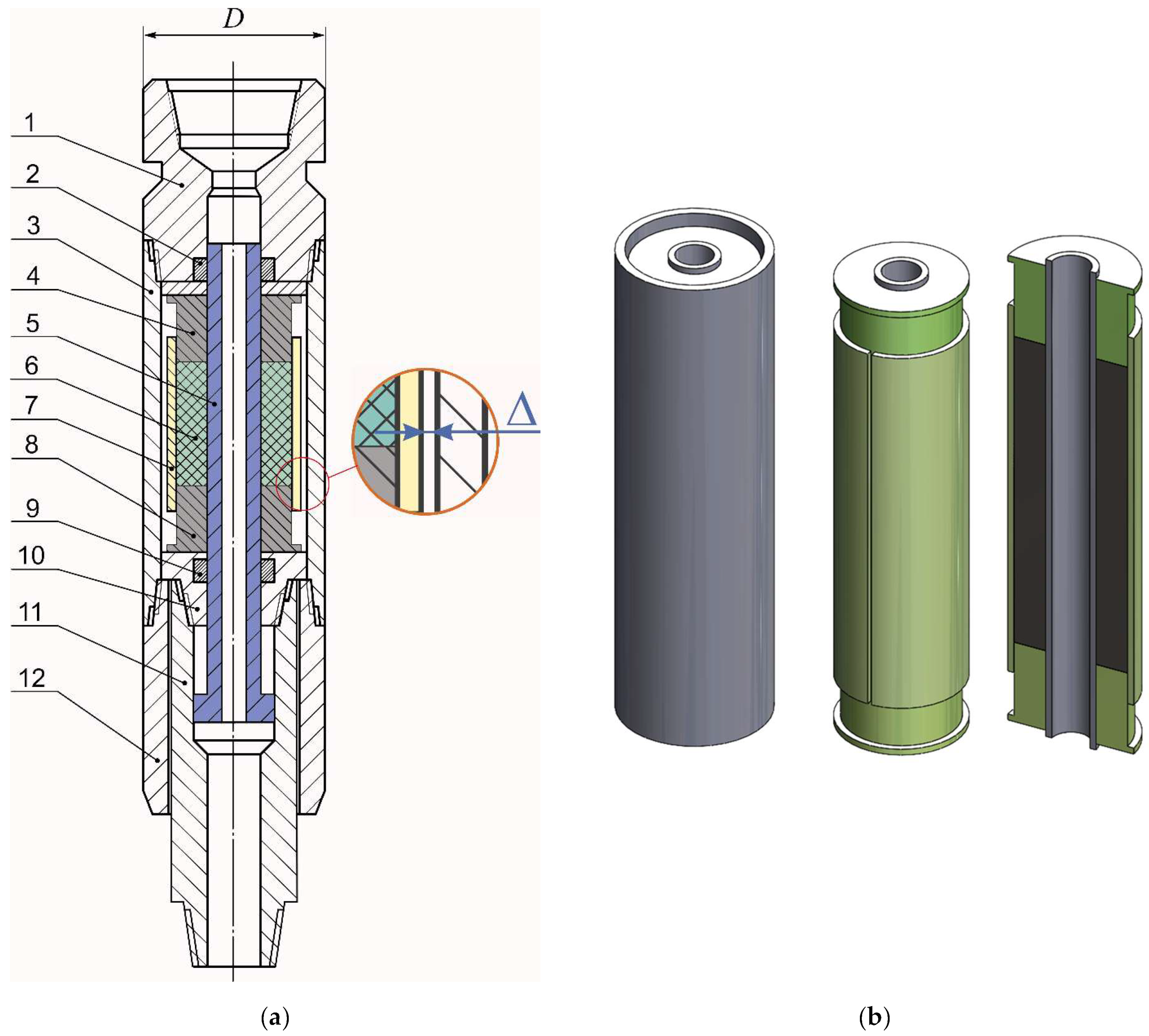
Figure 1. Design of adaptive drilling shock absorber (a) and general view of shell elastic element (b) with housing and without housing.
Vibration 08 00060 g001
Figure 2. Interaction scheme of adaptive drilling shock absorber components: 1—drilling shock absorber housing; 2—upper annular piston; 3—cylindrical shell cut along the generatrix; 4—weakly compressible elastic filler; 5—shock absorber shaft; 6—lower annular piston; 7—longitudinal construction slit in the shell.
Vibration 08 00060 g002
Figure 3. Finite element model of the shell elastic element with shaft.
Vibration 08 00060 g003
Figure 4. Displacements of the elastic element under loading Q = 95 kN: (a) radial displacements of the open shell; (b) axial displacements of structural components.
Vibration 08 00060 g004
Figure 5. Von Mises equivalent stresses in the open shell under loading Q = 95 kN.
Vibration 08 00060 g005
Figure 6. Deformation diagram of the elastic element (normal mode).
Vibration 08 00060 g006
Figure 7. Maximum equivalent stresses in the shell during zero-to-peak cycle (normal mode).
Vibration 08 00060 g007
Figure 9. Contact stresses on shell surface: (a)—under piston loading of 130 kN; (b)—under piston loading of 200 kN.
Vibration 08 00060 g009
Figure 10. Equivalent stresses in the shell: (a)—under piston loading of 130 kN; (b)—under piston loading of 200 kN.
Vibration 08 00060 g010
Figure 11. Entry of the open shell into contact with the housing: (a)—no load, uniform clearance between open shell and housing; (b)—under piston loading of 90 kN, clearance is non-uniform but still open; (c)—under piston loading of 100 kN, clearance closed in zones with azimuths of 90 and 270 degrees; (d)—under piston loading of 200 kN, clearance closed.
Vibration 08 00060 g011
Figure 12. Deformation diagram of shock absorber in emergency loading mode: (a)—maximum load 130 kN; (b)—maximum load 200 kN.
Vibration 08 00060 g012
Figure 13. Maximum equivalent stresses in the shell (emergency loading mode): (a)—zero-to-peak cycle 0–130–0 kN; (b)—zero-to-peak cycle 0–200–0 kN.
Vibration 08 00060 g013
Table 1. Geometric parameters of the elastic element of the drilling shock absorber.
Shock Absorber Diameter,
D, mm
Shaft Thickness,
h1, mm
Shaft
Radius,
R1, mm
Shell Thickness,
h2, mm
Shell
Radius,
R2, mm
Housing Thickness,
h3, mm
Clearance Value,
Δ , mm
Filler Length,
L, mm
240.010401090155500
Disclaimer/Publisher’s Note: The statements, opinions and data contained in all publications are solely those of the individual author(s) and contributor(s) and not of MDPI and/or the editor(s). MDPI and/or the editor(s) disclaim responsibility for any injury to people or property resulting from any ideas, methods, instructions or products referred to in the content.