1. Introduction
Passive-type dampers are the simplest means of controlling string vibrations [
1]. Semi-active vibration control has also been proposed as a more flexible alternative. This approach adjusts damping in real-time based on feedback signals, offering advantages such as adaptability to changing conditions and reduced power consumption compared to fully active control systems. Numerous studies have investigated semi-active techniques for string vibration control, aiming to enhance performance while minimizing energy usage and system complexity [
2,
3].
Active vibration control is essential for achieving a better performance in suppressing string vibrations. However, string structures are often installed at elevated or constrained locations, making it difficult to apply control forces directly to the middle of the string. A practical solution is to render one end of the string movable, thereby enabling control forces to be applied at the boundary. This has motivated the development of the concept of boundary control, in which control inputs are applied near the system boundaries to influence overall vibration behavior. Boundary control has been widely studied. Baicu et al. [
4] used a modified Lyapunov method to control the vibration of cables, demonstrating control performance through simulations and experiments. Il’in and Moiseev [
5] investigated the optimization of boundary control strategies under various boundary conditions. He et al. [
6] investigated adaptive boundary control for a flexible string system considering parameter uncertainties, while He and Ge [
7] explored model-based and adaptive boundary feedback control. Shi and Wang [
8] developed a strategy to enforce prescribed performance constraints and asymptotic stability in flexible string systems under external disturbance. Barseghyan [
9] developed optimal boundary control strategies for string vibrations using multipoint intermediate conditions, targeting specified deflections and velocities over time through a constructive control framework. Most existing boundary control strategies rely on Lyapunov-based formulations, which typically require both displacement and velocity measurements at the boundary. Although velocity can be obtained by differentiating between displacement signals, noise in displacement measurements often poses challenges to reliable differentiation in practice.
Different control algorithms have been applied to boundary control. Zhao et al. [
10] proposed adaptive neural-network-based fault-tolerant control and Fujino et al. [
11] implemented active stiffness control using piezoelectric actuators, while Alsahlani and Mukherjee [
12] utilized a scabbard-like actuator for control. Li et al. [
13] demonstrated controllers using energy harvesting-based self-powered active control, and a Linear Quadratic Gaussian (LQG) controller. However, many of these methods remain confined to numerical validation, and experimental demonstrations—particularly those addressing multi-mode control—are scarce. Additionally, the majority of these works adopt single-input–single-output (SISO) configurations, which are inherently limited to targeting individual modes. Given that string structures often exhibit significant resonance in both low- and high-order modes, such SISO-based approaches are insufficient for comprehensive vibration suppression.
In response to these limitations, this study proposes a boundary-actuated, displacement-based control strategy designed to suppress multiple vibrational modes. Specifically, a position-input–position-output (PIPO) controller is developed and implemented using only displacement sensors and a boundary actuator. This eliminates the need for velocity feedback and observer-based estimation, thus simplifying the system architecture while improving noise resilience. The controller is formulated in modal coordinates and designed to simultaneously attenuate the first three natural modes of the string. Unlike many prior studies, the proposed strategy is validated not only through simulation but also via real-time experimentation on a hardware platform. The results demonstrate that the controller achieves effective suppression of multi-modal vibrations, thereby bridging the gap between theoretical control design and practical implementation.
The remainder of this paper is structured as follows.
Section 2 formulates the dynamic model of the string with boundary actuation.
Section 3 presents the derivation and structure of the PIPO controller.
Section 4 discusses the estimation of modal coordinates from displacement measurements.
Section 5 and
Section 6 provide detailed numerical and experimental validation, respectively. Finally,
Section 7 concludes the paper with remarks on the applicability and future extensions of the proposed method.
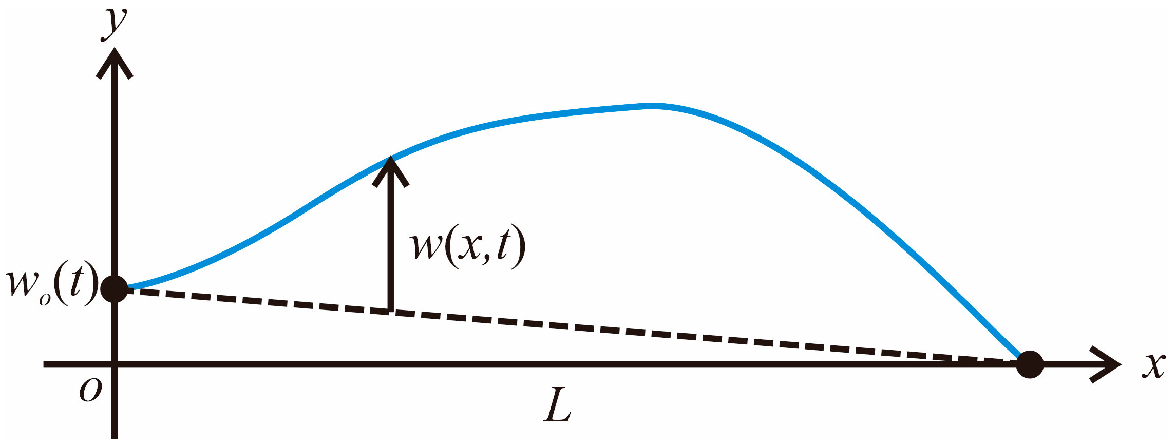
2. Equations of Motion for String with End-Displacement Actuation
Consider a uniform string of length
, as shown in
Figure 1. Assume that the point where
undergoes rectilinear motion of the boundary controller,
, along the
-axis and the other end at
is fixed.
represents the relative displacement of the string with respect to
. We aim to control the vibration of the string by using
and the proposed control algorithm.
The absolute displacement of the string may then be expressed as follows:
The kinetic energy and elastic energy, and virtual work of the string shown in
Figure 1, can be written as follows:
where
,
represents the mass per unit length of the string,
denotes tension, and
is the distributed external force acting along
, while
and
denote the virtual work and virtual displacement, respectively.
The assumed mode method is used as a numerical analysis technique. By discretizing the string displacement into a discrete system of multiple degrees of freedom using a non-dimensionless variable
in the length direction, the string displacement can be expressed as follows:
where
is a
matrix composed of admissible functions for string displacement, and
is a generalized displacement vector of size
, where
denotes the number of admissible functions. Assuming that the string is uniform, and using Equations (1) and (5), Equations (2)–(4) can be expressed as follows:
where
, and
To derive the equations of motion, the following Lagrange equation is used:
where
. By inserting Equations (6)–(8) into Equation (10), the following equations of motion can be derived:
The admissible functions of the assumed mode method utilize the eigenfunctions of a uniform string with both ends fixed, and are as follows:
Inserting Equation (12) into (9), we can obtain
where
is an
identity matrix and
is an
zero matrix. Dividing Equation (11) by
and using Equation (13), we can rewrite Equation (11) as follows:
where the modal damping matrix is added,
is an
matrix composed of damping ratios, and
Looking at Equation (14), it is evident that since we consider a uniform string, we obtain a decoupled modal equation of motion. However, the only controller we can use is a displacement controller attached to the end. In this case, the control algorithm becomes a multiple-input–single-output (MISO) system. However, since it presents a challenge to developing a control algorithm in the form of MISO, it is desirable to develop a control algorithm that can tackle each modal coordinate independently.
First, let us assume that we have
modal control forces and that we use these control forces to control
modal coordinates. Of course,
. Since the sum of the outputs of each controller corresponds to the actual displacement of the moving end, we can express the final end-displacement as follows:
where
is an
matrix consisting of ones,
is an
vector consisting of the outputs of each controller. Subsequently, the equations of motion, Equation (14) can be rewritten as follows:
When using Equation (17), since is an vector and is an vector, the number of controllers is insufficient. Therefore, when performing control, a control spillover problem to a higher-order mode occurs. However, this problem is not limited to the vibration control problem of the string dealt with in this study, but is a problem that always appears in the vibration control of a flexible structure with infinite degrees of freedom. Fortunately, since the damping for the high-order modes is large, solving the low-order vibration problem becomes a major task.
3. The Position-Input–Position-Output Control Algorithm
Equation (17) represents the equation of motion when modal coordinates are controlled by actuators. Looking at the equation of motion given in Equation (17), it is evident that the base displacement acts as an actuating force vector, and the modal displacement is generated by this force and an external disturbance force . The objective is to design a control algorithm that generates an appropriate control displacement using the sensor measurement of . This formulation naturally leads to the position-input–position-output (PIPO) control algorithm.
There are relatively few PIPO control algorithms proposed for vibration control. The most notable work is the PIPO control algorithm proposed by Kim et al. [
14], which considers a system where an actuator is connected in series with a spring damper. However, the governing equations of that system differ from those considered in this study.
Before addressing the vibration control problem of a multi-degree-of-freedom system, we first examine a single-degree-of-freedom vibrating system. Although this model is overly simplified, it offers valuable insight into closed-loop stability and control gain selection, forming the foundation for the MIMO implementation that follows. Based on Equation (17), the equation of motion of a single-degree-of-freedom vibrating system can be written as follows:
where
,
is generalized coordinate,
is damping ratio,
is gain,
can be regarded as control displacement,
is external disturbance, respectively. Unlike Equation (17), the time variable was non-dimensionalized using
to eliminate frequency dependency.
In this study, we propose the use of the following compensator equation to control the system whose equation of motion is given by Equation (18).
where
is the damping factor of the compensator. A controller in the form of Equation (19) has already been used in reference [
14]. However, the equation of motion of the system treated in reference [
14] is different from Equation (18). However, as suggested in reference [
14], we may expect that a control equation in the form of Equation (19) would be useful, so let us analyze what happens when this control algorithm is applied. The equation for the closed-loop control system given by Equations (18) and (19) can be combined and expressed as the following matrix ordinary differential equation.
Using the Laplace transform, Equation (20) is derived as follows.
where
,
,
. The characteristic equation of Equation (21) can be derived as:
By applying the Routh–Hurwitz stability criterion to Equation (22), it can be seen that the system is unconditionally stable if
. This result differs slightly from that reported in reference [
14], which states that a given system is stable only if
. This discrepancy arises because the equation of motion in Equation (18) differs from that used in reference [
14]. The stability condition
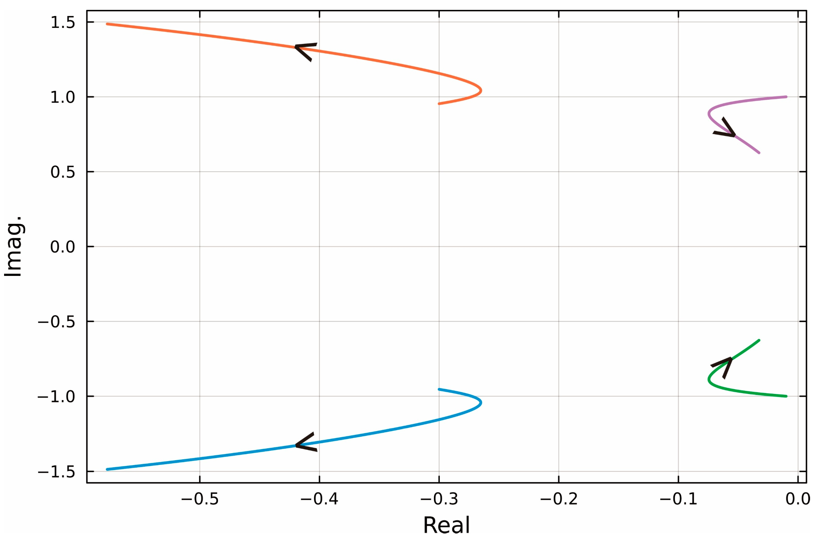
is a condition that is advantageous to the user when designing a controller. However, the question remains as to which gain value should be used. To explore this, a root locus analysis was performed with
,
, and a change in the gain from 0 to 1. The resulting pole trajectories are shown in
Figure 2. As illustrated in
Figure 2, the system poles initially move into the left half of the complex plane as the gain increases, indicating improved stability. However, beyond a certain point, the poles begin to approach the imaginary axis again. This observation suggests that simply increasing the gain does not necessarily lead to a better performance. Then, the question remains as to how much gain should be used.
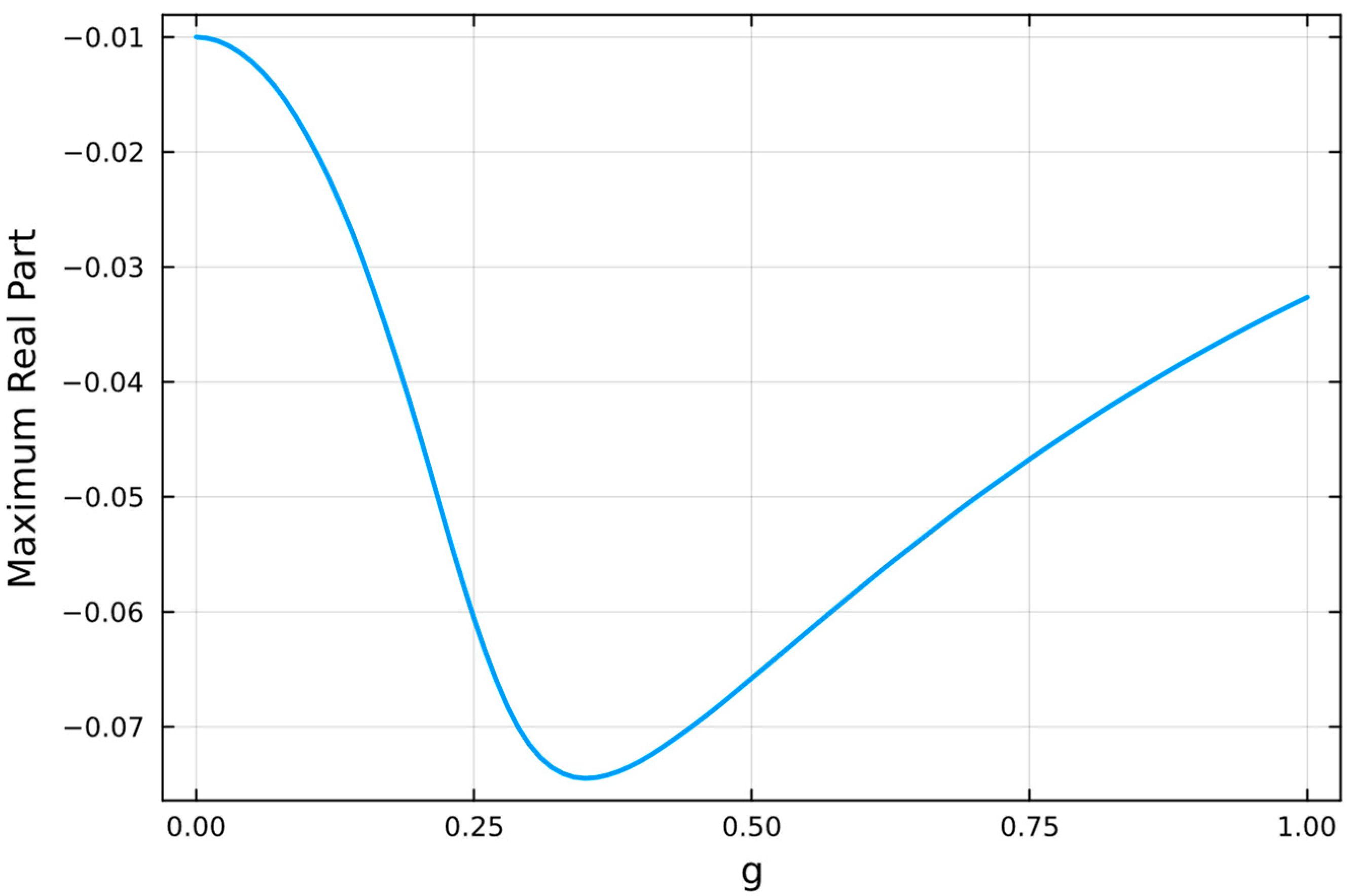
Figure 3 shows the maximum real part of the system poles as a function of gain. From
Figure 3, we can see that the gain reaches its minimum value at around 0.3. To gain a deeper understanding,
Table 1 summarizes how the natural frequencies, damping ratios, and settling times of the first three modes vary with the control gain. The range of gain values was selected around the baseline value of 0.3, as discussed earlier. A gain of 0 represents the uncontrolled case. The settling time
corresponds to the 2% criterion for a second-order system and is calculated using
. As the gain increases, the natural frequencies generally decrease. The damping ratios and corresponding settling times reveal a trade-off: while increasing the gain initially enhances control performance, excessive gain leads to reduced damping and slower responses. These results suggest that for the best performance, the gain should remain below 0.3 and be set as high as possible within that range, depending on actuator capacity and system constraints.
Now let us return to the equation of motion of the multi-DOF system, Equation (17). To control
modal displacements, at least
displacement sensor values are required. And we will assume
sensors are available. This implies that we consider the same number of equations of motion to be controlled as the number of sensors. In practice, it is not possible to use a large number of sensors to measure all modal displacements, so it should be kept in mind that a limited number of sensors are used. If we assume that m modal displacements can be measured and estimated by displacement sensors, we can propose a compensator equation for Equation (17) based on Equation (19) as follows:
where
is a matrix composed of gains,
is a matrix composed of damping ratios of the controllers and
is a sub-vector extracted from the original
vector, containing
components. Hence, we may write:
where
Using Equations (17), (23) and (24), the matrix equation for the following closed-loop system can be obtained:
4. Sensor Measurement
To compute
using the compensator equation, Equation (23),
is needed. However, it is impossible to measure
directly. In reality, we can measure only the absolute displacement of the string at the sensor points because the laser displacement sensors are mounted on the ground. Let
be the vector composed of absolute displacements measured by the sensors. Then, the relationship between
and
can be expressed as follows, using Equations (1) and (5):
where
Note that the modal displacement is truncated in Equation (24). In this case, an observer spillover problem occurs. Like the control spillover problem, this problem is inevitable, as it is impossible to measure all modal displacements for vibration control of a flexible structure with infinite degrees of freedom.
In practical controller implementation, a process is required to convert
to
using Equation (27) so that the following equation can be used to estimate the elastic displacements.
5. Numerical Analysis
Table 2 presents the properties of the string obtained from the string used in experiments. The natural frequencies of the string up to the third mode calculated using the data in
Table 2 are 2.95, 5.91, and 8.86 Hz.
To evaluate the control performance of the proposed MIMO PIPO control algorithm given by Equation (23), the frequency response functions of the uncontrolled and controlled systems were computed. In the numerical analysis, it is assumed that the point of applied disturbance is the same as the point of measurement.
A closed-loop block diagram for the addressed problem can be constructed as shown in
Figure 4. This block diagram is also used for the construction of the controller in the experiment.
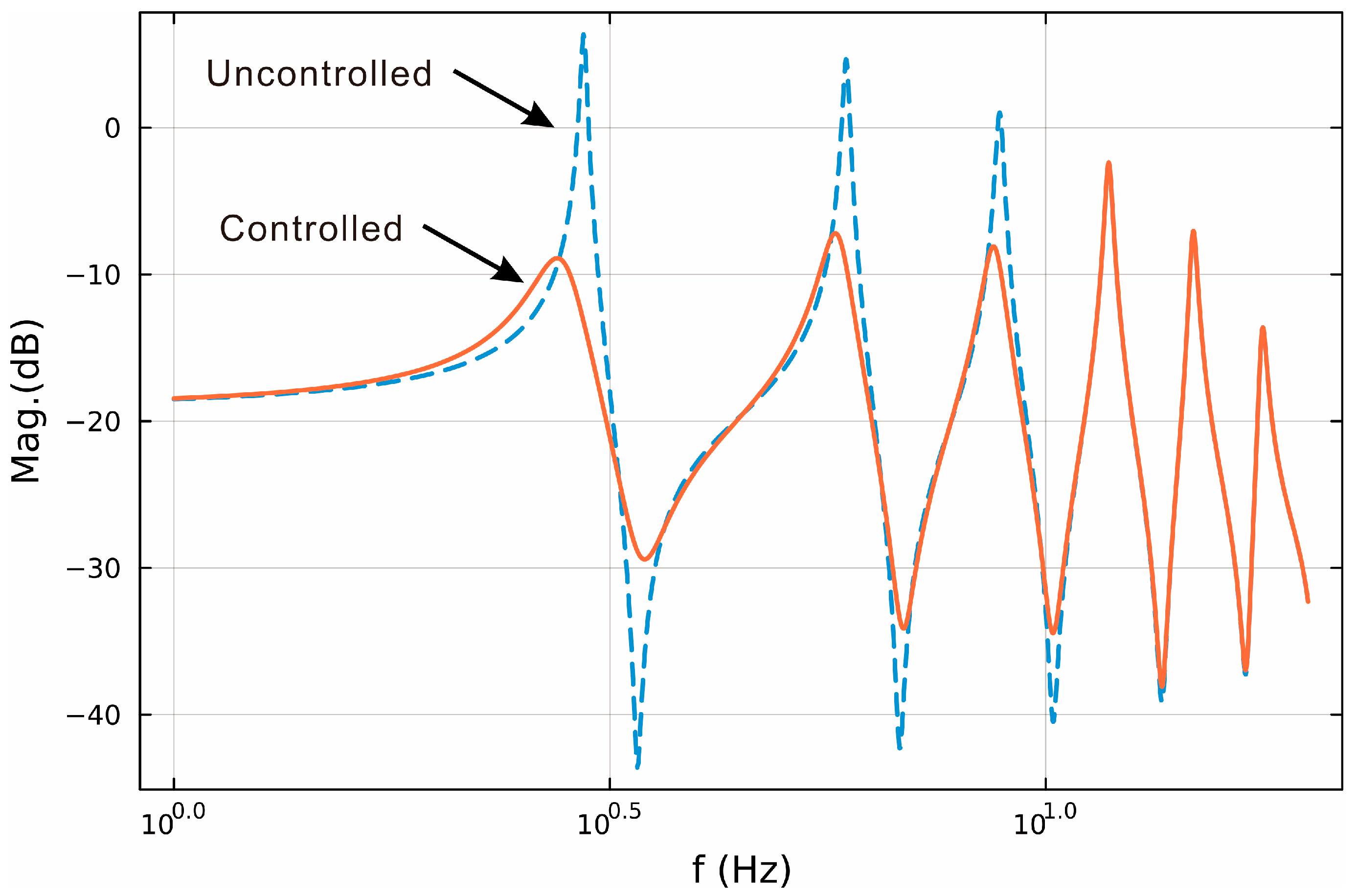
Figure 5 shows the frequency response functions of the uncontrolled and controlled systems. As shown in
Figure 5, the first, second, and third natural modes are effectively suppressed as designed. It is also evident that the higher-order modes are not influenced by controlling the lower modes. Detailed numerical values are provided in
Table 3. While a slight increase of approximately 0.06 dB is observed in modes above the third, this corresponds to only about a 0.69% increase in magnitude, which is considered negligible. That is, the control spillover problem does not occur. Therefore, it was confirmed that the control methodology developed in this study can be effectively used for the vibration suppression of the string.
Figure 6 shows the impulse response, which shows that the vibration is suppressed even though all modes are excited. The modal damping ratios were estimated before and after applying the control algorithm. For the first mode, the damping ratio increased from 0.0079 to 0.0665; for the second mode, from 0.0083 to 0.0387; and for the third mode, from 0.0098 to 0.0291.
6. Experiments
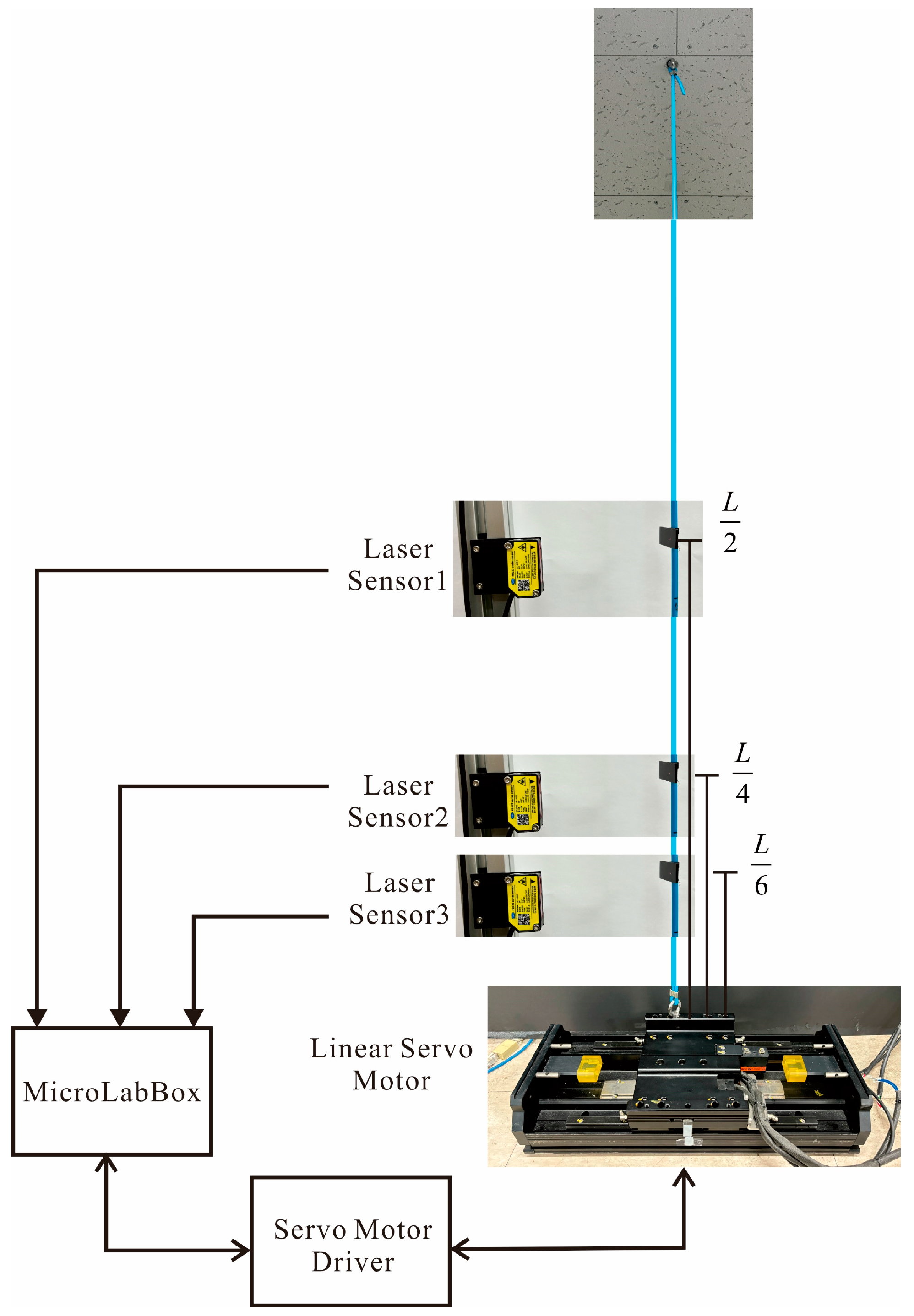
Even if the validity of the control algorithm is proven through theory and numerical calculations, it is necessary to prove that control is possible using an actual string. An experimental testbed such as
Figure 7 was constructed to control the vibration of the string.
The top of the string was fixed to the ceiling, while the bottom was secured to a linear motor. The displacement of the string was measured using a laser displacement sensor (FUWEI Model FSD22-100P) (Guangzhou Fuwei Electronic Technology Co., Ltd., Guangzhou, China), while the base was moved using a linear servo motor (Mitsubishi Electric Model LM-H3P2A-07P-BSS0) (Mitsubishi Electric, Tokyo, Japan). Displacement measurements were taken at
, considering these as the points where the displacement amplitudes for the first, second, and third modes, respectively. The control algorithm proposed in this study was downloaded to MicroLabBox of dSpace Inc. (dSpace Inc., Paderborn, Germany)The output of the control algorithm given by Equation (23) is the position of the end. Therefore, in order to make the position of the linear servo motor be at the calculated position in real time, the servo motor driver is set to the speed mode, and the position of the servo motor measured by the encoder is compared with the desired position, and the error obtained is provided to the PID control algorithm, which calculates an appropriate speed change and provides it to the motor driver. For a control method that can accurately track the position in real time using a linear servo motor, refer to reference [
15].
The experimental setup consists of a taut string with its top end fixed to the ceiling and the bottom end connected to a linear servo actuator (Mitsubishi Electric LM-H3P2A-07P-BSS0). The actuator is driven by a servo amplifier (MR-J4-40A-RJ) (Mitsubishi Electric, Tokyo, Japan) operating in speed control mode. The real-time controller (MicroLabBox by dSpace Inc.) calculates the desired end displacement according to the proposed control algorithm, Equation (23), and the resulting signal is converted to a velocity command using a PID position tracking loop based on encoder feedback. The encoder used is an incremental-type optical encoder (Renishaw RGH22 with RGS40-S scale) (Renishaw, Wotton-under-Edge, UK) with a resolution of 0.5 μm. The displacement responses of the string were measured at selected points corresponding to the anti-nodes of the first three natural modes using laser displacement sensors (FUWEI FSD22-100P), which offer an accuracy of approximately ±0.1 mm. The control algorithm was implemented via Simulink and executed at a sampling frequency of 1 kHz, with an overall real-time latency of approximately 1–2 ms including I/O processing and computation.
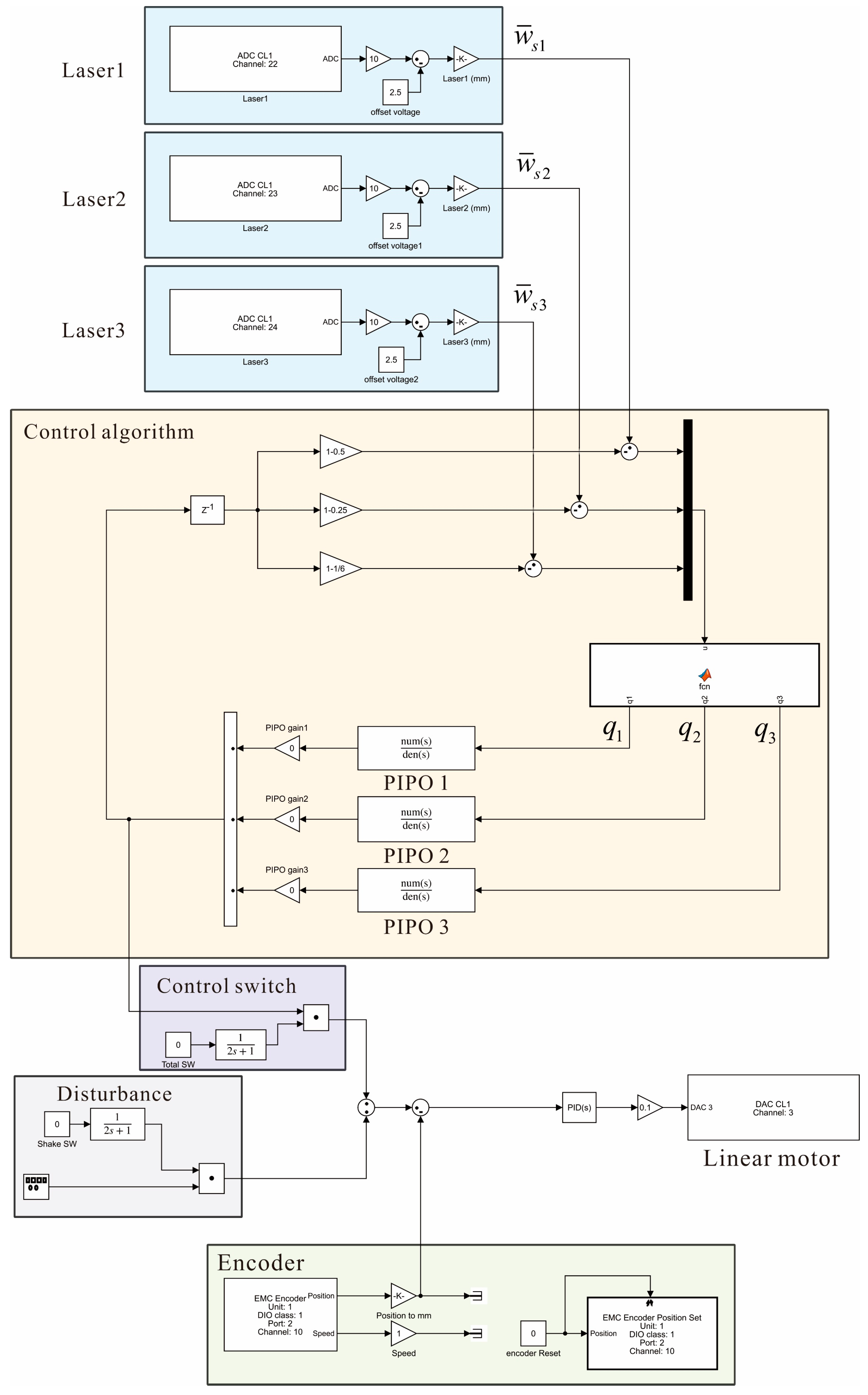
In the experiment, since the absolute displacement
is measured, it is necessary to transform it into
using Equation (29).
Figure 8 shows the Simulink block diagram of the controller for the experiment. Through free vibration experiments, the natural frequencies of the string were confirmed to be (2.95, 5.9, and 8.9) Hz and each PIPO controller was tuned to each natural frequency. The gains of the controller were all set to 0.15, which were determined through trial and error during the experiment.
To compare the control performance when multiple modes are simultaneously excited, we conducted experiments by applying an impact at the
point.
Figure 9 shows the uncontrolled and controlled vibration response when an impact is applied.
Figure 9 presents the vibration responses with and without control under the same impact condition. As shown in the figure, the proposed control algorithm effectively suppresses the vibrations induced by the initial impact. Since the impact was applied manually, the input force did not exactly replicate the idealized input used in the numerical simulations. This mismatch likely caused slight discrepancies in the excitation of higher-order modes. Nevertheless, the overall experimental result closely resembles the numerical response shown in
Figure 6, confirming the practical effectiveness of the proposed controller.
Figure 9 shows that the vibrations due to impact can be quickly suppressed when the control algorithm proposed in this study is used, but the control performance for each natural mode needed to be confirmed again. Therefore, experiments were conducted to see whether the control performance shown in
Figure 7 is the same in the experiment when each natural mode is excited and the controller is driven. To this end, an experiment was designed to initially excite harmonically at the target natural frequency and then change the mode to the vibration control mode, and the response was measured.
Figure 10 shows the vibration response measured by the first laser sensor installed at position
when excited at the first natural frequency mode.
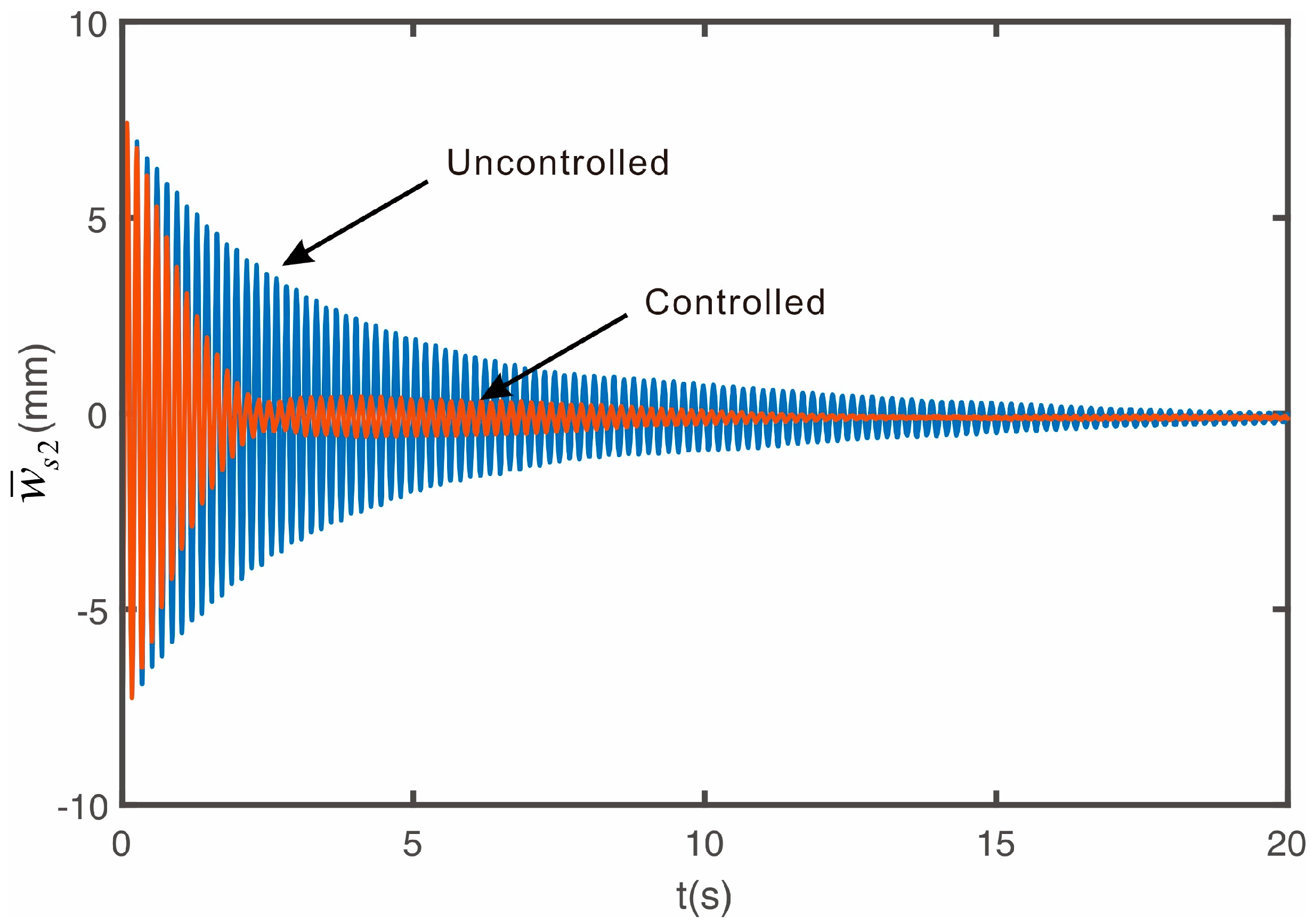
Figure 11 shows the vibration response measured by the second laser sensor installed at position
when excited at the second natural frequency mode.
Figure 12 shows the vibration response measured by the third laser sensor installed at position
when excited at the third natural frequency mode. The experimental results confirm that the MIMO PIPO controller proposed in this study effectively controls up to the third natural mode, as in the case of numerical simulations. The presence of very small residual vibrations in the controlled state is due to the input voltage being lower than the servo motor’s minimum input voltage, resulting in a dead band in the servo motor, which implies that it is not easy to control low-amplitude higher natural modes.
The modal damping ratios were estimated before and after applying the control algorithm. For the first mode, the damping ratio increased from 0.0079 to 0.0394; for the second mode, from 0.0083 to 0.0303; and for the third mode, from 0.0098 to 0.0179. These improvements are somewhat smaller than the theoretical predictions, primarily because the control force was gradually increased over a 2 s interval to ensure system stability and prevent an abrupt motor response. This smooth ramping strategy reduced the initial control’s effectiveness.
7. Conclusions
In this study, we investigated the design of an active vibration control system for a string equipped with a displacement-type boundary actuator and multiple displacement sensors. Based on the derived equations of motion, a position-input–position-output (PIPO) control algorithm was proposed for the suppression of string vibrations.
Prior to developing the multi-input multi-output controller, a single-degree-of-freedom system was analyzed to introduce the PIPO control concept. Using this simplified model, we derived the closed-loop stability condition and found that the system remains unconditionally stable for any positive gain. This suggests that the controller is robust and easy to implement, with further analysis indicating the existence of an optimal gain.
Building on the theoretical insights gained from the single-mode system, the control algorithm was extended to a multi-input system for string vibration control. The controller operates in the modal domain, consisting of a sum of individual modal controllers, and utilizes displacement measurements from multiple sensors to determine the control input to the actuator.
The performance of the proposed controller was validated through both numerical simulations and experimental tests conducted on a flexible string with one end connected to the actuator. Using three displacement sensors, the controller was designed to suppress vibrations up to the third natural mode. Both simulation and experimental results confirm that the proposed MIMO PIPO controller is effective in suppressing multiple vibrational modes in a string structure.


