Article

Soil–Structure Interaction and Damping by the Soil—Effects of Foundation Groups, Foundation Flexibility, Soil Stiffness and Layers

Federal Institute of Material Research and Testing, 12200 Berlin, Germany
Vibration 2025, 8(1), 5; https://doi.org/10.3390/vibration8010005
Submission received: 8 December 2024 / Revised: 10 January 2025 / Accepted: 23 January 2025 / Published: 31 January 2025

Abstract

:
In many tasks of railway vibration, the structure, that is, the track, a bridge, and a nearby building and its floors, is coupled to the soil, and the soil–structure interaction and the damping by the soil should be included in the analysis to obtain realistic resonance frequencies and amplitudes. The stiffness and damping of a variety of foundations is calculated by an indirect boundary element method which uses fundamental solutions, is meshless, uses collocation points on the boundary, and solves the singularity by an appropriate averaging over a part of the surface. The boundary element method is coupled with the finite element method in the case of flexible foundations such as beams, plates, piles, and railway tracks. The results, the frequency-dependent stiffness and damping of single and groups of rigid foundations on homogeneous and layered soil and the amplitude and phase of the dynamic compliance of flexible foundations, show that the simple constant stiffness and damping values of a rigid footing on homogeneous soil are often misleading and do not represent well the reality. The damping may be higher in some special cases, but, in most cases, the damping is lower than expected from the simple theory. Some applications and measurements demonstrate the importance of the correct damping by the soil.

1. Introduction

The behaviour of railway tracks under dynamic vehicle loads and the transfer from the ground vibration to buildings are highly influenced by the soil–structure interaction. The interesting frequency range is typically high (up to 100 Hz) and flexible foundation structures have to be considered. In the research work on railway-induced ground and building vibrations, several interaction and damping effects have been analysed individually. The main results are summarised here to properly introduce them in the prediction of railway-induced track, bridge, soil, and building vibration. As the material damping of the structure (wood, concrete, or steel) is generally low, the high radiation damping of the soil is often important as the limiting factor of the resonance amplitudes. Moreover, for foundation structures like railway tracks, the soil–structure interaction analysis is indispensable.
The history of soil–structure interaction is long [1,2]. In the beginning, only rigid foundations were calculated [3,4,5,6] as earthquakes with long wavelengths and very stiff nuclear power plants were of interest. The influence of the soil–structure interaction on the behaviour of tall buildings was another topic, where small changes of the natural frequency have been quantified in detail [7]. This influence is stronger for mid- and low-rise buildings [8,9]. In the last decades, the influence of the resonance amplitudes of railway bridges [10,11] and wind energy towers [12,13,14] for stability and fatigue problems have come into the focus.
Railway problems are challenging because of the high frequencies and the many wavelengths which have to be considered within the foundation. These problems can be solved by large finite-element models including all parts of the track, bridge or tunnel, soil, and building [15]. Substructuring is a meaningful method to reduce the computational effort [16,17]. The boundary element method reduces the modelling of the soil to a minimum [18], and some methods have been developed [19] which can further reduce the calculation effort. Meshless methods such as the method of fundamental solution (MFS) [20] or the singular boundary method (SBM) [21] use a superposition of fundamental solutions at collocation points near or on the boundary of the soil, in the case of the latter, with special methods to resolve the singularities. The present results are established by an indirect boundary element method [14] which includes all these ideas where the singularity at the excitation point is solved by an appropriate averaging over a surface area. The boundary element method for the soil is coupled with the finite element method to include the foundation flexibility which is important for the high frequencies of railway problems.
This article presents the stiffness and damping of different types of foundations and is structured as follows. The Section 2 presents the coupled finite-element boundary-element method, and Section 3 presents the methods for measurement and evaluation. The calculated results are presented in three main sections, the stiffness and damping of rigid single and group foundations in Section 4 for homogeneous soil and in Section 5 for layered soil, and the compliance in amplitude and phase for the flexible foundations (tracks, piles, beams, and plates) in Section 6. Finally, in Section 7, some application and measurement examples for the influence of the soil on the vibration of a block foundation, a building or parts of the building, a wind energy tower, and railway tracks are presented. The conclusions emphasise the necessity of the accurate inclusion of the soil–structure interaction and its damping effects in railway dynamic problems.

2. Methods of Calculation

2.1. The Standard Symbols and Parameters

The following symbols are used throughout the text:
  • displacements u;
  • particle velocities v;
  • forces F or P;
  • dynamic stiffness K = F/u;
  • dynamic compliance C = u/F;
  • impedance F/v;
  • admittance v/F;
  • frequency f;
  • circular frequency ω = 2πf;
  • imaginary unit i or j.
The standard parameters for the soil are as follows:
  • shear modulus G = 2, 4.5, 8, 13 × 107 N/m2;
  • Poisson’s ratio ν = 0.33;
  • mass density ρ = 2000 kg/m3;
  • material damping D = 2.5%.
This results in the following:
  • shear wave velocity vs = 100, 150, 200, 300 m/s;
  • compressional wave velocity vP = 2vS;
  • wave impedance Z = √ = G/vS = ρvS.
The other material parameters are as follows for concrete:
  • elasticity modulus E = 3 × 10¹⁰ N/m2;
  • mass density ρ = 2500 kg/m3.
And they are as follows for steel:
  • elasticity modulus E = 2.1 × 10¹¹ N/m2,
  • mass density ρ = 7800 kg/m3.

2.2. The Finite-Element Boundary-Element Method

The basis of all methods is the point load solution (Green’s function) for a layered soil. These functions are calculated by the following procedure. For each layer with thickness d, shear modulus G, and shear and compressional wave velocity vS and vP, a 4 × 4 symmetric stiffness matrix is calculated in wavenumber domain k. All layer matrices and the matrix of the underlying half-space are assembled in a stiffness matrix KS of the whole soil body, which is inverted to a compliance matrix N. The appropriate elements of this compliance matrix, for example, Nzz(k, z1, z2) for an interior source at z1 and an interior response at z2, are integrated over the wavenumber k to obtain the displacement at a distance r of the source.
F z z ( r , z 1 , z 2 ) = 1 2 π 0 N z z ( k , z 1 , z 2 ) J 0 ( k r ) k d k
Similar formulae for all components of the Green’s function F are derived in a simple way.
These Green’s functions are used in a combined finite-element boundary-element method (FEBEM) to establish a boundary stiffness matrix of the soil (in the frequency domain, for n discrete points). A displacement matrix is compiled directly (meshless) by using the point-load solutions.
u(xβ) = F(xβxα) p(xα) uβ = Fβα pα
At the loading point, this would yield infinite values (singularities). Therefore, the mean values on the cylindrical (in the case of a pile) or circular surface (in the case of a surface foundation) are calculated as the diagonal elements of the displacement matrix.
u α = 1 A α A α F x x α p x α d A         u α = F α α   p α
The force matrix of the soil is the identity matrix, as the Green’s function has no stresses at the soil surface and the stresses in the interior do not yield forces at another pile element (as far as the dimension is small compared to the distance and wavelength). Thus, the inverse of the displacement matrix U = [Fαβ]α,β = 1,n is the dynamic boundary stiffness matrix KS of the soil. This matrix is transformed to the rigid body coordinates by appropriate transfer matrices in the case of rigid foundations. For flexible structures, the boundary matrix of the soil is added to the finite-element stiffness matrix KB of the structure to yield the global dynamic stiffness matrix KS + KB of the combined structure–soil system, and the FEBE method is complete.
This coupled FEBE method was introduced in the 1980s [22] where the application of the boundary element method to soil dynamic problems started [23]. Similar approaches have been presented at the same time in [24,25]. Meanwhile, many coupling methods of FEM and BEM have been developed [26]. The contact points of the structure to the soil must be discretised by a set of points where the distance must be smaller than one-fifth of the shear wavelength of the soil—see Section 6 for some examples. As the dynamic stiffness matrix of the soil is fully populated, the number of nodal points highly influences the computational effort. Therefore, the contact area to the soil could be increased with the development of computational power, from 5 m × 5 m for a plate to 10 m × 10 m for a small building to 20 m × 60 m for a large building. The results of this FEBE method have been validated against wavenumber domain results in [27,28], against finite element results in [14], and in a benchmark test for railway tracks [29]. Some comparisons with measurements are shown in Section 7.

3. Methods of Measurement and Evaluation

The vibration velocity of the structure, the foundation, and the soil is measured by geophones Geospace HS1. The exciting force is measured by an instrumented hammer PCB 086D50 (PCB Piezotronics, New York, NY, USA). The signals are filtered, amplified, converted, and stored in a 72-channel DIFA-SCADAS measurement system. The evaluation is carried out by self-written analysis procedures.

3.1. Material Damping from Attenuation with Distance

The material damping of the soil is usually described as a hysteretical damping with a complex shear modulus [3].
G = G0(1 + i2D).
That is a description for harmonic excitations and means that the damping ratio D is constant for all frequencies. In general, the stiffness G0 and the damping D depend on the strain amplitudes. The damping increases and the stiffness decreases for high strain amplitudes. For the low strain amplitudes considered here, the stiffness and damping are constant and the linear theory can be applied. The material damping of the soil yields an attenuation of wave amplitudes with distance or with the number of waves. Therefore, short wavelengths at high frequencies lead to strong attenuation effects.
The material damping D can be evaluated from the attenuation of the amplitudes with distance. The amplitude–distance relation can be written as follows:
A = C r*n exp(−2πDr*)
with r* = r/λ being the distance r related to the wavelength λ. Such an equation holds for every measured frequency and distance. The logarithm of these equations results in a set of linear equations of the unknown parameters n, D, and ln C:
ln A = ln Cn ln r* − 2πDr*.
The best approximation of these equations is calculated by giving the geometrical attenuation n, the material damping D, and the ln C. The resulting approximate amplitude distance curve is shown in Figure 1, together with the measured points. The geometric attenuation is close to the theoretical value of n = 1/2. The material damping for that measuring site is D = 2.7%, which is a quite normal value. The typical range for the material damping of the soil is 1 to 5%, and a standard value of D = 2.5% is used for the present calculations.

3.2. Modal Damping from the Approximation of Frequency Response Functions

A measured admittance function v/F can be approximated by a hysteretically damped single-degree-of-freedom system:
v F = i ω k + i d m ω 2
The admittance is a non-linear function of the parameters k—stiffness, d—damping, and m—mass. The reciprocal function, however, the impedance
F v = k + i d m ω 2 i ω
is a linear function of k, d, and m. The latter equation is multiplied with the measured transfer function H = v/P and its conjugate H*:
H = k + i d m ω 2 i ω H H
The solution of this system of 2nF equations (the real and imaginary part for each of the nF frequencies) yields the approximation of the measured admittance function. The weighting function w(f) = H*H is essential in order to obtain reasonable results. This simple approximation method also provides the modal parameters’ eigenfrequency
f o = 1 2 π k m
and damping
D = k 2 d
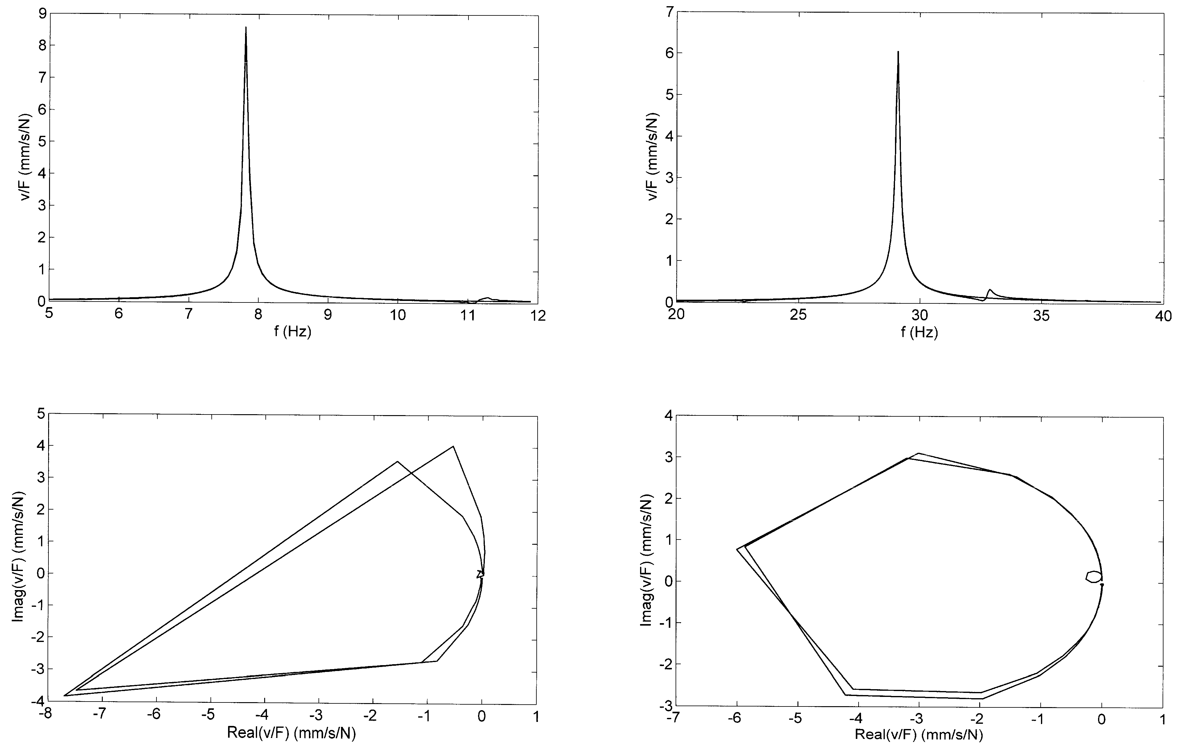
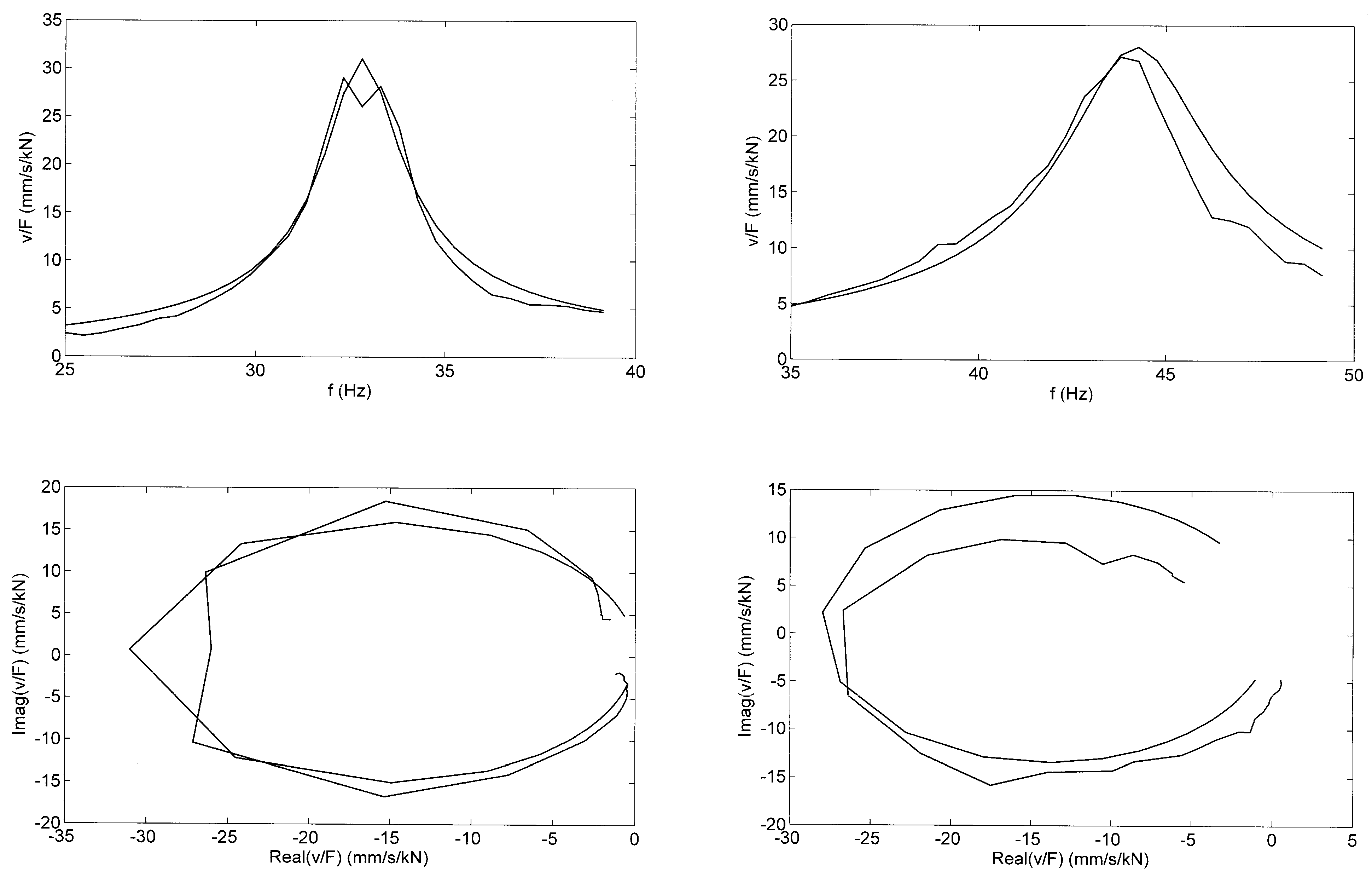
The method has been applied to an 8 m-long steel beam in the laboratory. The first and the second eigenfrequency f1 = 7.9 Hz and f2 = 29 Hz are well-represented as amplitude curves and in the complex plane (Figure 2). A low damping of D = 0.28 and 0.27% has been determined for the laboratory conditions, which refers mainly to the material damping of steel. Real-world systems are coupled to the soil and the modal damping also includes a contribution of the radiation damping into the soil, as will be shown in Section 7.3 for floors in buildings.

4. Damping and Stiffness of Rigid Foundations on Homogeneous Soil

The complex dynamic stiffness K of a foundation on the soil is usually written as follows:
K = k +iωc
with the stiffness k and the damping c. In general, the stiffness and damping are frequency-dependent and the following dimensionless parameters are normally used:
a0 = /vS            dimensionless frequency
k/k0 = k/Ga           dimensionless stiffness
ωc/k0a0 = c/ωvSa2 = cvS/Ga2 = c/Za2 dimensionless damping
The shear modulus G, the shear wave velocity vs, and the impedance Z of the soil, and a dimension a of the foundation (the radius, a (half-)width, or a length) are used for these parameters.

4.1. Damping and Stiffness of Rigid Footings

The stiffness and damping of a square foundation of 2a × 2a on homogeneous soil are shown in Figure 3 (the curves with marker ☐, and in Figure 4 and Figure 5) for the vertical, horizontal, rocking, and torsional degree of freedom. These curves are almost constant with frequency. Only the damping of the rotational component curves is clearly frequency-dependent. They start with zero damping at zero frequency and increase to a higher, rather constant value. The vertical stiffness and damping values are as follows:
k 3.4 G A and c 1.6 G ρ A
for the standard value ν = 0.33 used for the calculation. These formulae also hold for an equivalent disc foundation with the same foundation area, which is often used as a reference [3]. The stiffness is proportional to the shear modulus of the soil and the dimension of the foundation (the square root of the foundation area A). The damping c is proportional to the product of the wave impedance and the foundation area. The absolute damping c is increasing with the stiffness of the soil, but the relative damping
c k ~ a v S
is decreasing with the stiffness (the wave velocity) of the soil. The relative damping is relevant for limiting the resonance amplifications V, for example,
V = 1 2 D = k 2 c   ω 0
for a single-degree-of-freedom system. The damping ratio D depends on the resonance frequency because of the viscous character of the radiation damping of the soil in contrast to the frequency-independent hysteretical material damping. The stiffness k and the damping ωc are equal at a certain frequency:
f C = 1 2 π k c   ~   v S a
which is lower for soft soils. For higher frequencies, the damping iωc is the dominating part of the dynamic stiffness K.
An embedded foundation (depth e) has a larger area of contact with the soil, and, therefore, the stiffness and, particularly, the damping are increased. The increase in the vertical degree of freedom can be expressed as follows:
k = k 0 1 + 0.5 e r
c = r v S 0.8 + 0.35 e r k   k 0 r v S 0.8 + 0.75 e r
for a cylindrical embedded foundation of radius r [5,6]. This means that the additional contact area contributes considerably to the stiffness and damping of the embedded foundation.

4.2. Vertical Damping and Stiffness of Group and Strip Foundations
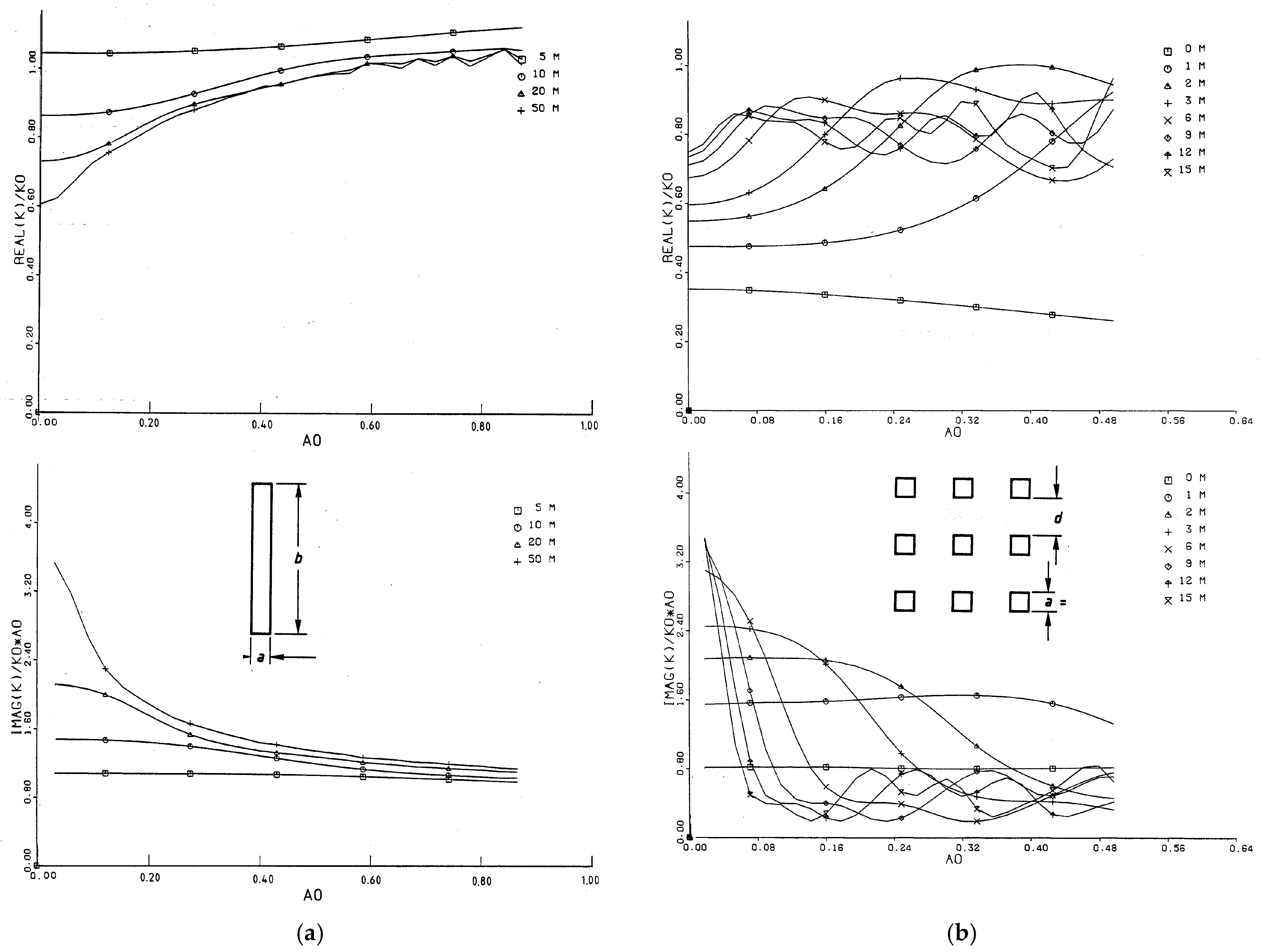
At first, strip foundations of length
b = 5, …, 50 m
and width
a = 1 m
are analysed. The frequency-dependent stiffness and damping are shown in Figure 6a for different foundation lengths, where the reference stiffness is
k0 = Gb/(1−ν),
the normalised frequency is
a0 = ωa/vS
with the width of the foundation, and the reference damping is
c0 = k0 a/vS
The stiffness and damping functions both approach a limit value of nearly 1 at high frequencies, the damping from above, and the stiffness from lower values. If the length is 5 m (the length-to-width ratio is b/a = 5), the low- and high-frequency values are the same, and that means that stiffness and damping are similarly constant as those for the square or the equivalent disc foundation. The stiffness of longer strip foundations is ruled by their length, and the damping of long (strip) foundations is determined by the area of the foundation. At low frequencies, these values are modified. The low-frequency stiffness is smaller, decreasing with the increasing length of the strip foundation. The low-frequency damping is higher, increasing for longer foundations. The modification for the damping is clearly stronger than the modification of the stiffness.
Figure 6. Normalised stiffness and damping of (a) a strip foundation of width a = 1 m and length b = ☐ 5, ◯ 10, △ 20, and + 50 m, a0 = /vS, k0 = Gb/(1−ν); and (b) a group of 3 × 3 foundations of area A = 1 m × 1 m with distance d = ☐ 0, ◯ 1, △ 2, + 3, ✕ 6, ◇ 9, and ↑ 12, ✕ 15 m, a0 = /vS, k0 = 9 × k1.
Vibration 08 00005 g006
The second example is a group of 3 × 3 square footings of 1 m × 1 m in a distance which has been varied between
d = 0 … 15 m.
The stiffness functions in Figure 6b are normalised by the stiffness of nine equivalent disc foundations, and the frequency parameter is
a0 = ωr/vS
with the equivalent radius r of a single footing. The high-frequency functions show characteristic variations around a limit value which corresponds to the sum of the single stiffness and damping values. The low-frequency damping is much higher than the limit, and the low-frequency stiffness is lower than the corresponding limit. The low-frequency differences are twice as strong for the damping, at a factor of 4 compared to a factor of 2 for the stiffness. Moreover, the corresponding frequency range is also much wider for the damping. The low-frequency effects are due to the interaction between the different parts of the foundation. This effect is strong if the foundation parts are within a wavelength distance, and it becomes weaker when the wavelengths are shorter at higher frequencies. Therefore, the frequency range of a higher damping and lower stiffness is smaller for the wider group foundations in Figure 6b.
The following rules hold for group foundations. The maximum stiffness is the sum of the single stiffnesses:
k(d→∞) = Σki = nk1,
The minimum is for the distance of d = 0
k(d = 0) ≈ kO = √n k1
which is the stiffness of the equivalent disc foundation. The sum c of the single dampers ci is the same as the damping of the equivalent disc foundation, and the whole situation can be summarised as follows:
cstat > cO = ccdyn
kO < kstat < kdynk
Moreover, for low frequencies, the relation
c ~ k2
holds, which confirms the observation in the calculated results, and, by dimensional analysis, it can be concluded that
c ~ k2/GvS.
The same rules can be used for the strip foundation which can be regarded as a group of smaller foundations of a length-to-width ratio of b:a = 5:1.

4.3. Building Foundations

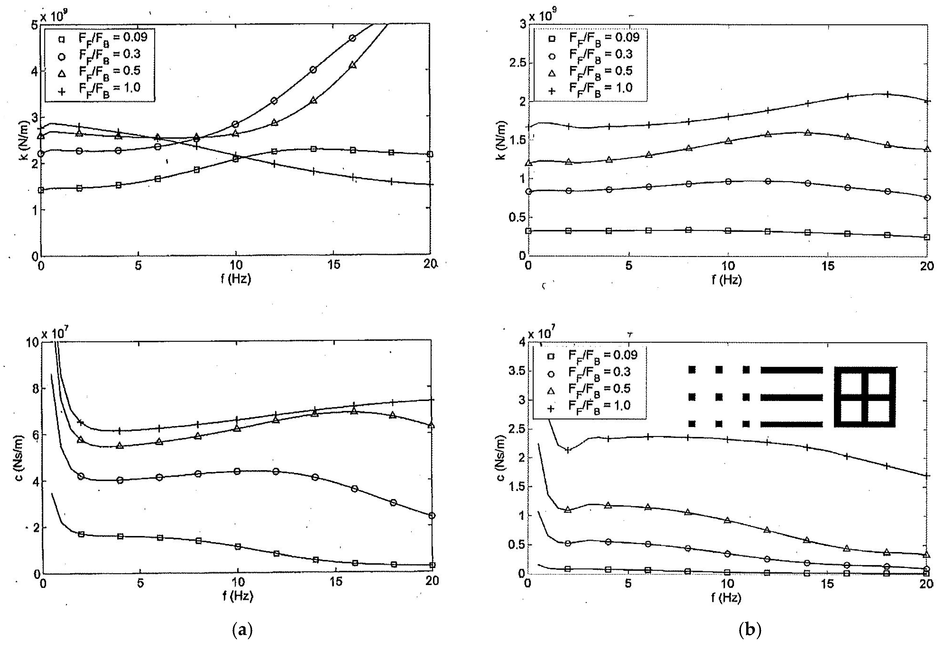
The following types of realistic building foundation are considered (Figure 7). A number of equally spaced individual footings (as in the preceding section) are calculated, as is typical for office or industrial buildings. Parallel strip foundations or frames of strip foundations are typical for residential buildings. The stiffest type of foundation, a plate foundation which covers all the building area FF = FB, is included in this parameter study for completeness. The outer dimension of the building is 7 or 10 m. The width of the strip or single foundations is varied between 0.5, 0.7, and 1.0 m.
As a result, the stiffness and damping values of the rigid group foundations are presented as a function of frequency (0 to 20 Hz). Figure 7a shows the results of the different foundations of a = 10 m. Generally, the variations with frequency are weak. Only the stiffness of the plate foundation (FF/FB = 1) has a reduction with frequency. For the other foundations with (FF/FB < 1), the stiffness tends toward higher values at higher frequencies. The damping is also nearly constant. Only the single footings show a reduction at high frequencies in agreement with the preceding section. (The high values approaching 0 Hz are due to the hysteretic material damping of the soil D = 2.5%.)
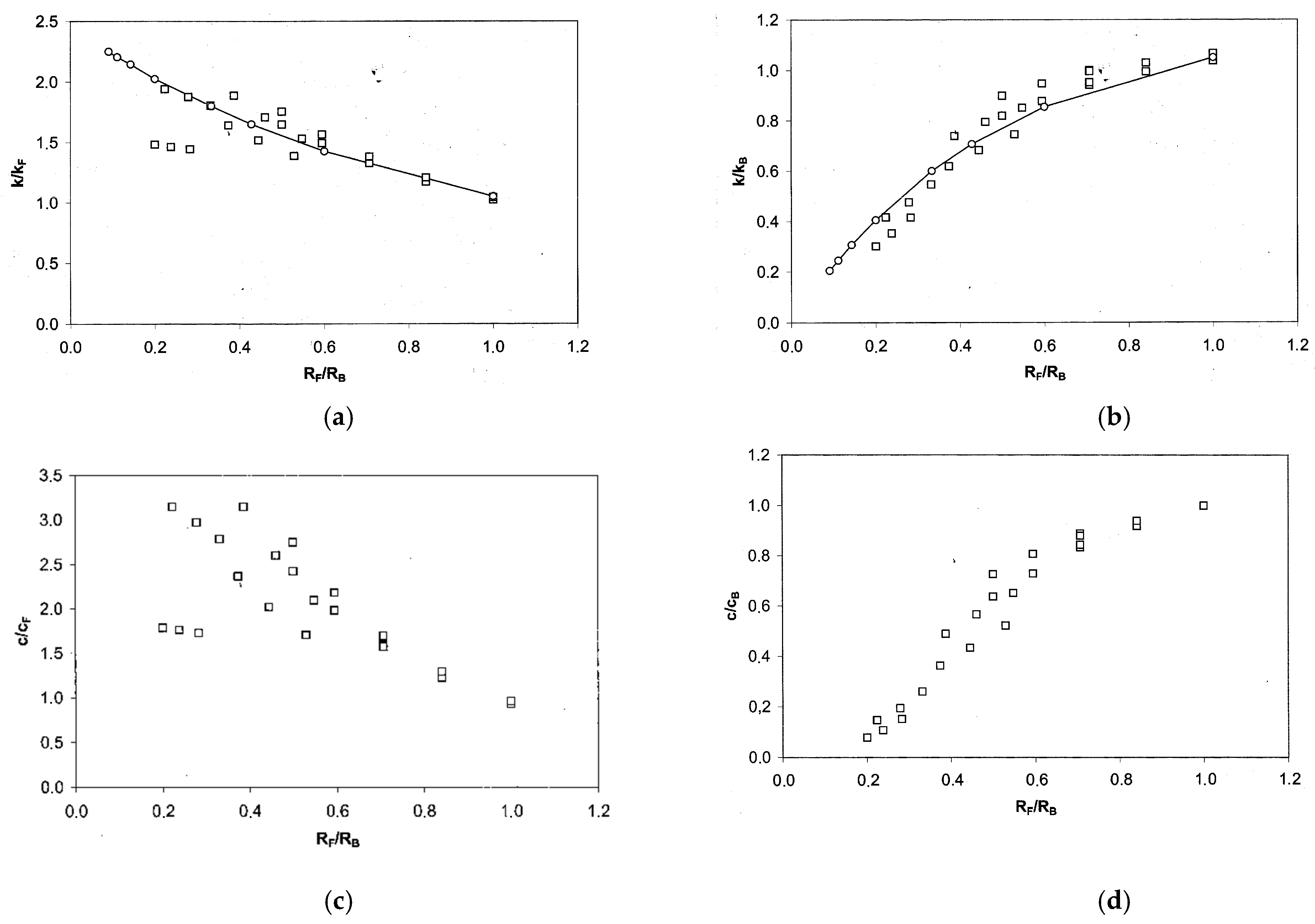
The static and low-frequency values of the calculated stiffness and damping functions have been evaluated for the whole parameter study. They can be compared with the formula of an equivalent disc foundation and are given as a function of the ratio RF/RB with the radii
R F = F F π   and   R B = F B π
in Figure 8. For the equal radii RF/RB = 1 (or equal areas), the calculated stiffness ratio k/kF is one. If the foundations are distributed over a wider area (RF/RB < 1), the stiffness is higher than the stiffness of a concentrated disc foundation. The highest calculated stiffness ratio is k/kF = 2 for the group of individual foundations. Another comparison is made with the stiffness kB of a completely covered building area. In Figure 8b, once again, the value one is obtained for the plate foundation. Nearly the same value is obtained by foundations for RF/RB > 0.5. Only foundations, which cover a minor part of the building area, have a considerably smaller foundation stiffness.
The same evaluation has been carried out for the low-frequency damping of these foundation groups (Figure 8c,d). The same rules can be stated but the deviations from the equivalent and from the total plate foundation are stronger for the damping. The highest value compared to the equivalent plate foundation is c/cF = 3.5, and the lowest value compared to the total plate foundation is c/cB = 0.1. The variation of the damping is clearly stronger than the variation of the stiffness.
The exact stiffness and damping values are between the two limits, the stiffness of a foundation of the same total area and the stiffness of a square foundation of the (larger) building area. The strip foundations are closer to the latter limit, whereas the single footings are better approximated by the lower values of the disc with the same foundation area.

5. Stiffness and Damping of Rigid Foundations on Layered Soil

The best radiation of energy occurs for homogeneous soil. Any inhomogeneity or layering of the soil would reduce the energy radiation and, therefore, the damping of the foundation.
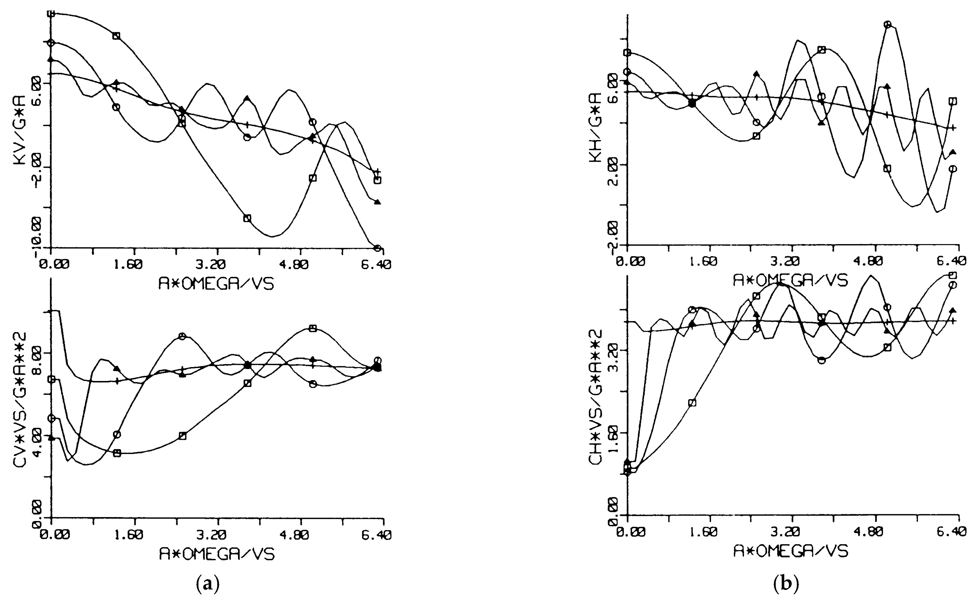
The effects of a soil layering on the stiffness and damping of all components of a square foundation are shown in Figure 3 where a soft layer with shear wave velocity vS1 of height h over a stiffer half-space with vS2 has been calculated. The velocity contrast vS2/vS1 has been varied up to a factor of 10, and the soft soil has been used for the normalised quantities. For all components, the static and low-frequency stiffness are increased compared to the stiffness of the homogeneous soft soil. A factor of 2 is reached for the vertical component, and 1.5 is the maximum value for the horizontal component. On the other hand, the low-frequency damping is reduced considerably. The damping is slowly increasing and the stiffness is decreasing with frequency. A minimum of the stiffness and a rapid change in the damping occurs around the characteristic frequencies fH = vS1/4h for the horizontal and torsional mode and fV = vP1/4h for the vertical and rocking mode where fV = 2fH holds for the standard ν = 0.33. The stiffness can be zero or even negative when the velocity contrast is high. At high frequencies, the damping and the stiffness approach—with some oscillations—the values of the homogeneous soft soil. That means that the damping can be higher than the homogeneous damping if the frequency is above the characteristic layer frequency. All these characteristics of a layered soil are strongest for the vertical component, strong for the horizontal component, weak for the rocking component, and weakest for the torsional component.
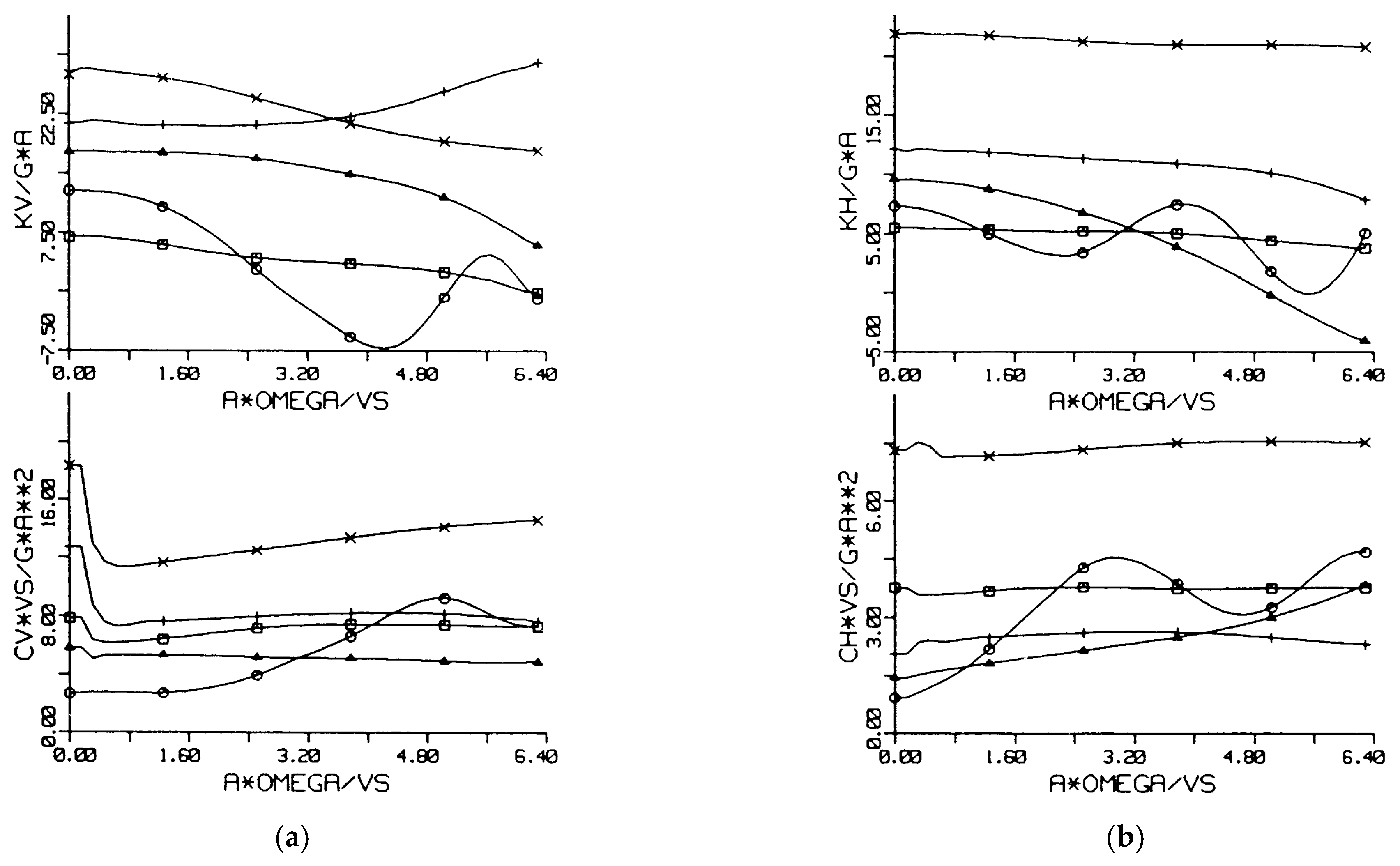
The effects of layering are reduced in their strength and in the frequency range when the thickness of the layer increases (Figure 4), and, for h/a → ∞, the values of the homogeneous soft soil are reached. On the other hand, the values of the stiffer underlying half-space are expected for very thin layers. Figure 5 shows the corresponding results for thin layers and the homogeneous soft and stiff values for comparison. The characteristic layer frequencies are high for thin layers so that the low-frequency range is much wider. In this wide frequency range, the stiffness increases with thinner layers approaching the higher values of the stiff half-space in the vertical direction, whereas the horizontal stiffness reaches only half of the half-space value. The damping of the thin layers is reduced in the whole frequency range and reaches only the lower values of the softer half-space. These characteristics of a thin layer are stronger for the horizontal component. Generally, the top layer of the soil has a strong influence on the foundation stiffness and damping. This has also been found for the rigid building foundations of Section 4.3 where a 1 m-thick top layer of soft soil with vs = 70 m/s reduces the stiffness to 50% and the damping to 15% of the stiff homogenous values (Figure 7b compared to Figure 7a).

6. Damping and Stiffness of Flexible Foundations

Railway tracks, piles, beams, and plates are analysed for a vertical point-load excitation. A horizontal point load is additionally considered for the pile foundation, and two point loads on the two rails are used in the case of the railway track (Figure 9i). The strong effect of flexible foundations is that they react with a more local displacement to a concentrated load. The deformation patterns of the analysed flexible foundations are shown in Figure 9. It can be seen that tracks, plates, beams, and piles show strong deformations which are more local around the loading point with increasing frequency. Moreover, for high frequencies, wave-type responses can be observed, which are due to the mass in combination with the stiffness of the structure.

6.1. Damping and Stiffness of Railway Tracks

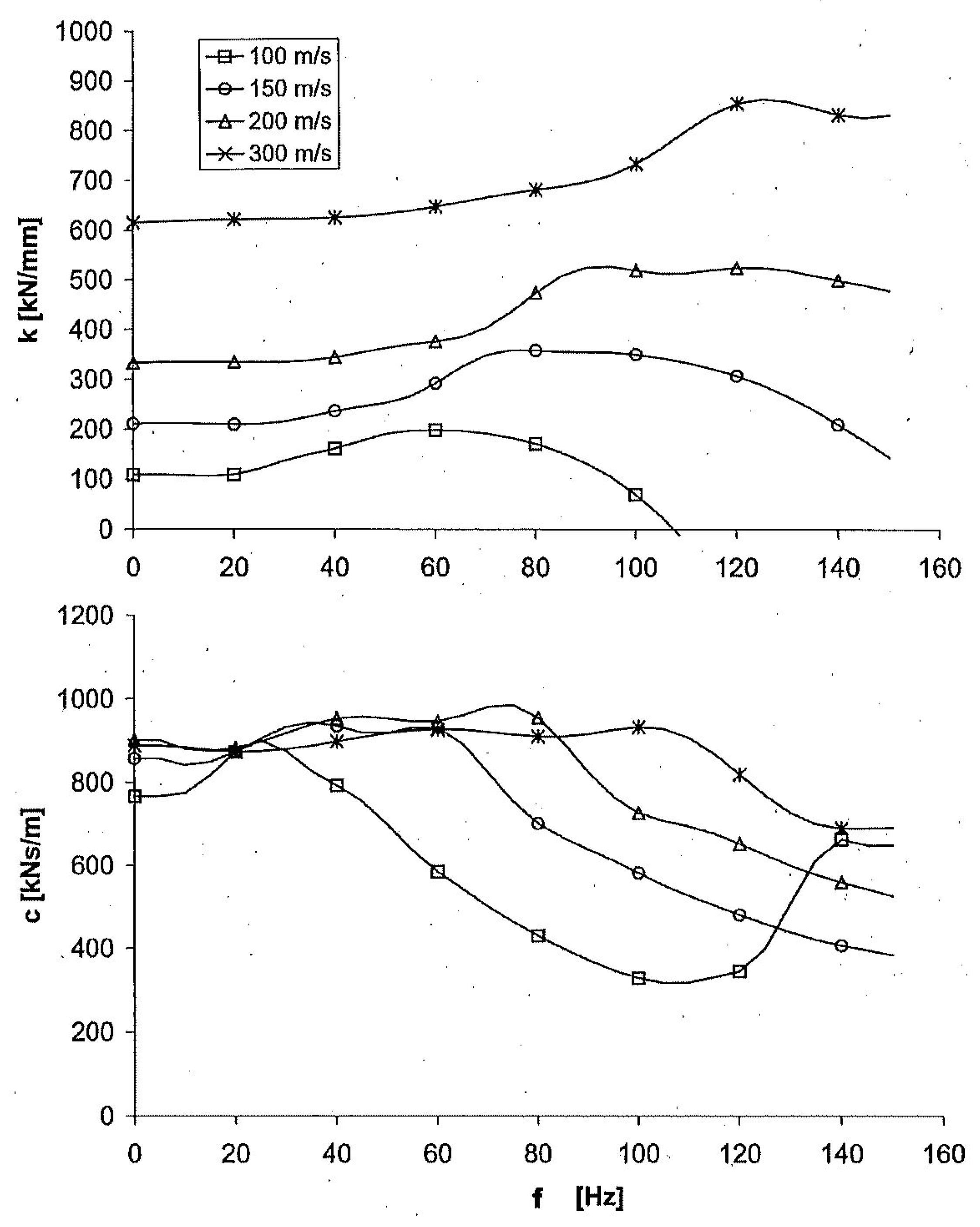
Railway tracks are flexible foundations which are dynamically loaded by passing trains. Frequencies up to 150 Hz are excited, for example, by the sleeper passage excitation of a high-speed train with a speed of 300 km/h. The stiffness and damping of a track consisting of sleepers (with dimensions of 2.6 m × 0.26 m × 0.2 m) at a distance of d = 0.6 m, and of two (UIC60) rails with m’ = 60 kg/m and EI = 6 106 Nm2 are shown in Figure 10 for this frequency range and for different soils. The stiffness of the track is clearly increasing with the stiffness of the soil, whereas the differences in the damping are small. The stiffness is approximately k~G0.75, and, with the relation between the low-frequency damping and stiffness,
c ~ k2/GvS = (G3/4)2/GvS ~ G3/2/G3/2 = 1
the almost soil-independent damping can be explained. The frequency-dependent characteristics are similar to the characteristics of foundation groups. The stiffness is increasing and the damping is decreasing with frequency. Besides this interaction effect of different parts of the track, this is also a typical effect of flexible foundations.

6.2. Vertical and Horizontal Damping and Stiffness of Piles

The stiffness and damping of 10 m-long piles with a 1 m diameter are shown for the vertical and horizontal excitation at the pile head in Figure 11. The vertical and horizontal behaviours are quite different. The same pile behaves more like a rigid pile in the vertical direction, whereas it is more flexible in the horizontal direction. The horizontal stiffness is weaker than the vertical stiffness. If the pile stiffness is increased, the vertical stiffness and damping are approaching the rigid limit earlier than the horizontal ones. A vertical resonance (a zero stiffness) can be found at about 60 Hz due to the mass of the pile and the compliance of the soil. The horizontal stiffness and damping functions are regularly increasing with the pile stiffness and decreasing with the frequency. This special effect of flexible foundations will be discussed in the next section.

6.3. Dynamic Compliances of Beam and Plate Foundations

The frequency-dependency of the stiffness k and damping c suggests a different presentation as the amplitude and phase of the compliance function, where the increase in the phase with frequency is proportional to the relative damping and, therefore, an indicator for the damping (of structural resonances). Figure 12 shows the compliance function for a 10 m-long concrete foundation beam of a 0.5 m × 0.5 m cross-section on different soils. A strong influence of the soil on the beam foundation is found at low frequencies. The static compliance C0 depends on the soil stiffness as follows:
C0 ~ G−0.75
The influence of the soil is considerably reduced at high frequencies where the four amplitude curves of different soil stiffnesses come close together. It is concluded that beam properties determine the behaviour at high frequencies. No resonance maximum occurs for these beam–soil systems. The compliance amplitude decreases monotonously with increasing frequency and the phase delay increases to values of more than 100°. These amplitude and phase changes with frequency are the strongest for the softest soil. In contrast, the stiffest soil has almost constant amplitudes and the weakest and a constantly increasing phase delay.
The next variation tries to extract the influence of the width of the beam foundation. The foundation width is studied for extreme values from very small, a = 0.1 m, and rather wide, a = 3 m, and no other parameter than the foundation width is changed. With the width a, the influence of the soil is modified, yielding quite different characteristics (Figure 12b). A weak resonance occurs at 60 Hz in the case of the very narrow foundation with a = 0.1 m. This reflects the fact that a considerable mass is supported by a small soil area. For a higher frequency, this amplitude function decreases rather strongly and the curve comes close to the other curves. For larger foundation widths, the curves decrease more smoothly from the static value and they show no resonance effect, although the phase delays reach values higher than 90°. The phase decrease is higher for larger foundation areas and that means that the damping by the soil is increased with the foundation area. The phases at high frequencies are in reverse order, and the widest foundation has the lowest phase delay. This is, once again, an effect of the different damping of the different foundation areas, which results in lower phase delays above the resonance frequency for wider foundations.
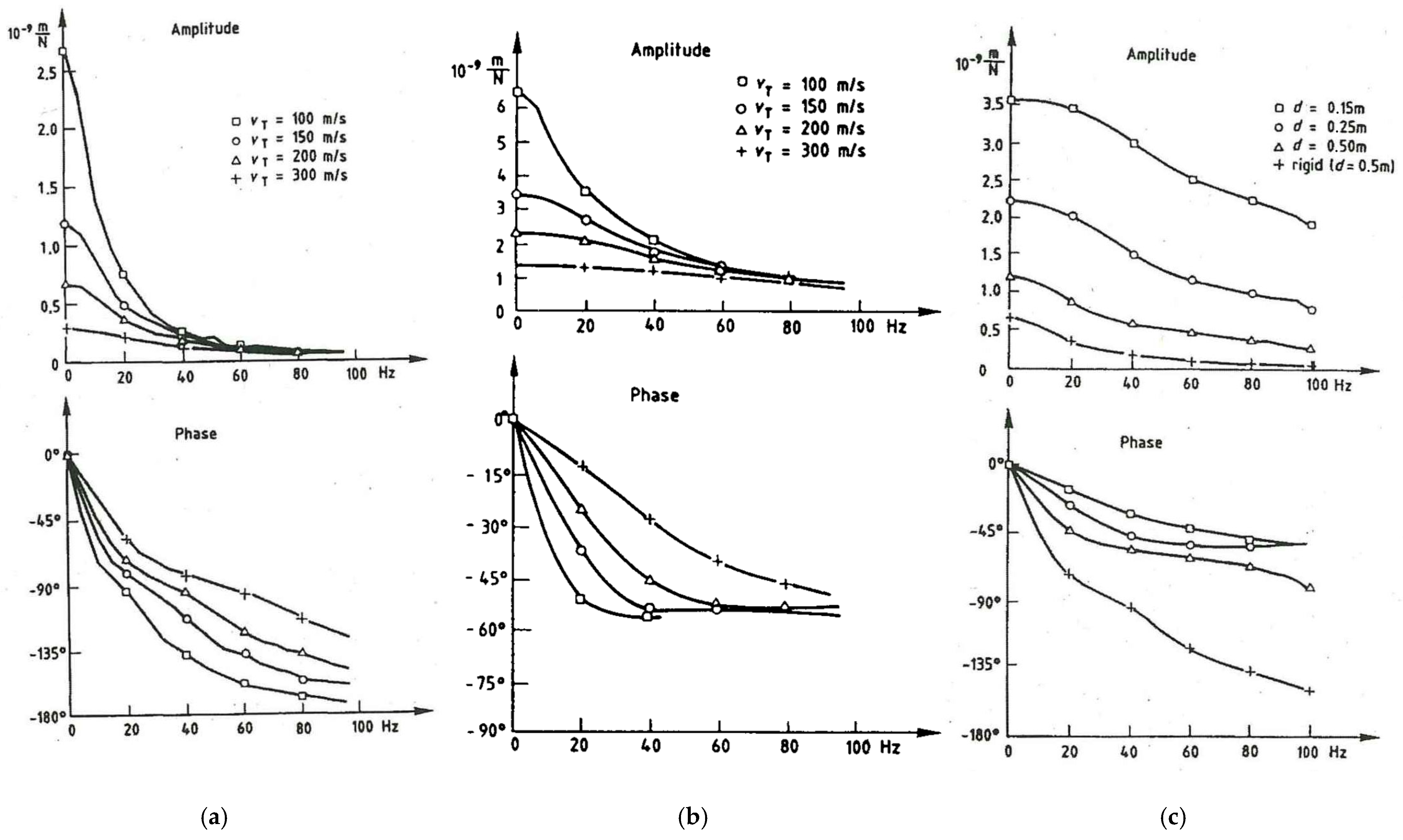
Figure 13 shows the amplitude and phase of the compliance for a 5 m × 5 m-wide and 0.25 m-thick plate on different soils. If the plate is rigid (Figure 13a), there is a strong decrease in the amplitude and a strong decrease in the phase, which is mainly due to the mass at the high frequencies. The decrease with frequency is strongest for the softest soil. If the same plate is considered as flexible with the material parameters of concrete (Figure 13b), the decreases in amplitude and phase are much smaller. The phase delay is not greater than 50°, whereas it tends toward 180° for the rigid plate. The compliance amplitude varies the most strongly with the different soils in the static case, but not as strongly as for the rigid plate where the static amplitude follows the law u/F~1/vS2. At high frequencies, the different amplitude curves come close together, for the flexible as well as for the rigid plate. Moreover, the phase curves of the flexible plates seem to reach a common limit value. In consequence, the high-frequency behaviour of the flexible plate is almost independent from the soil properties and ruled mainly by the properties of the structure. This is confirmed by Figure 13c where the thickness of the concrete plate is varied from 0.15 to 0.5 m.
The behaviour of a finite flexible plate on the soil approaches the behaviour of an infinitely wide plate for which the following asymptotic expressions for the dynamic stiffness hold [27]
K ~ B1/3 G2/3
for low frequencies when the static stiffnesses are dominant,
K ~ B1/2 (Z iω)1/2 =~ B1/2 ()1/4 iω1/2 with φ = 45°
in a mid-frequency range when the damping of the soil is stronger than its stiffness and stronger than the mass effect of the plate, and
K ~ B1/2 m‘‘1/2 iω with φ = 90°
when the mass of the plate is dominating. The corresponding rules for an infinitely long beam on the soil are [28]
K ~ EI1/4−q G3/4 + q
for low frequencies when the static stiffnesses are dominant,
K ~ EI1/4−q G (Z iω)3/4 + q with φ ≥ 67°
in a mid-frequency range when the damping of the soil is stronger than its stiffness and stronger than the mass effect of the beam, and
K ~ EI1/4 m‘3/4 (iω)3/2 with φ = 135°
when the mass of the beam is dominating. The rules for the bending of piles are almost the same as for the bending of beams—see [14], where the additional power q has also been derived.
These asymptotes clearly describe the observed phenomena:
The influence of the structure is increasing with frequency;
The structure is dominating the behaviour at high frequencies;
The soil is dominating the behaviour at low frequencies;
The influence of the soil is decreasing with frequency;
The damping is decreasing with frequency and is not a viscous damper as for a rigid foundation.
The special characteristics of flexible foundations must be observed in many practical applications such as wind tower or railway track vibrations.

7. Applications and Measurements

7.1. Response of a Foundation Block to Different Impact Excitations

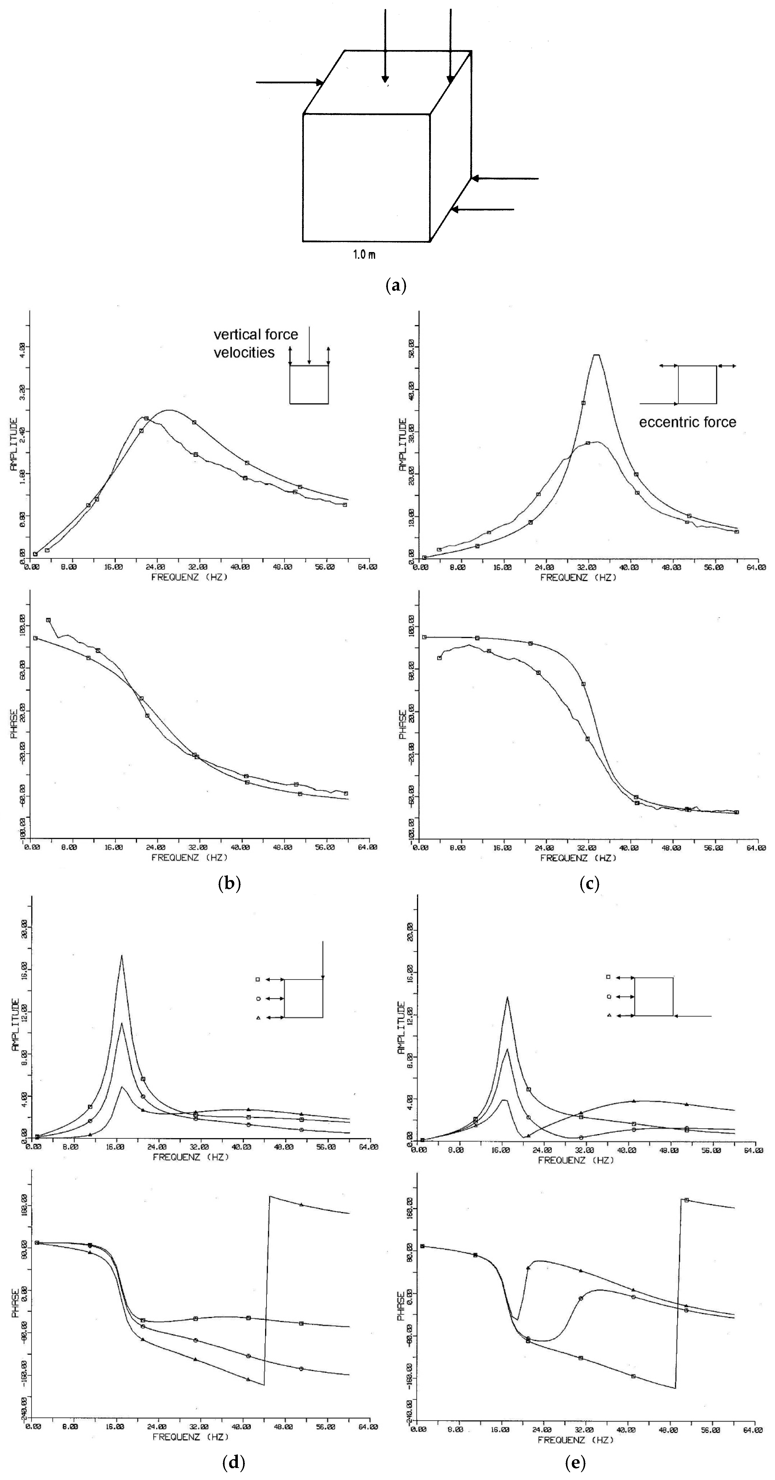
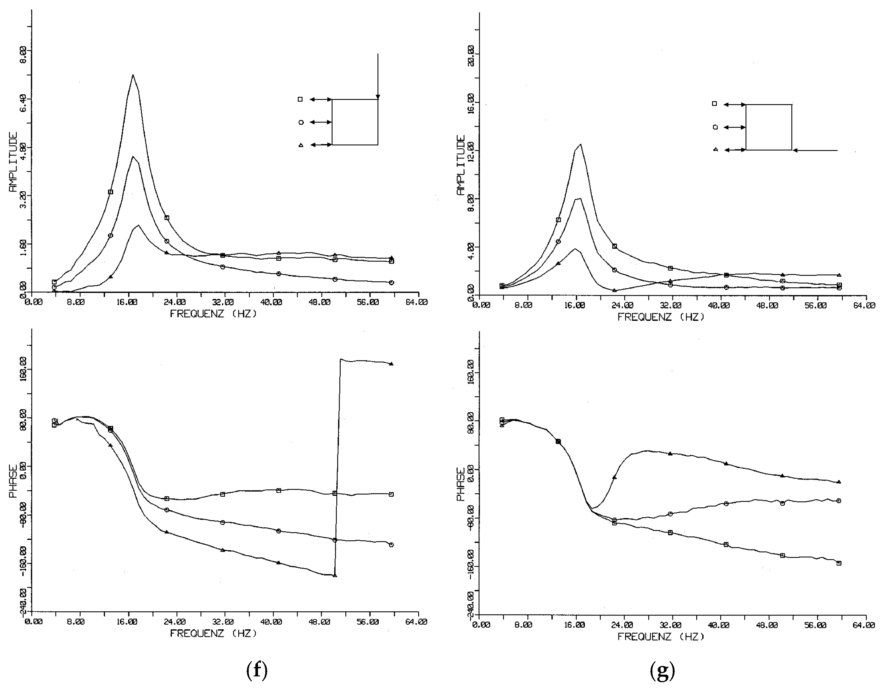
A concrete block of 1 m × 1 m × 1 m was built on the soil, instrumented with twelve velocity sensors (geophones) and measured under hammer excitation at different points in different directions (Figure 14a). As the hammer force F is measured, admittance functions v/F are calculated and presented as the amplitude and phase in Figure 14a–g. The experimental results are compared to theoretic results for a rigid block on homogeneous soil with a shear wave velocity of vs = 100 m/s.
The vertical vibration as well as the torsional one (the rotation around the vertical axis) can be separated from all other modes (Figure 14b,c). The vertical resonance is at 25 Hz, the torsional one at 32 Hz. Certainly, the experimental curves are not as smooth as the calculated ones, but the agreement in frequency and amplitude is very good. (The little higher damping of the torsion could be a high-frequency effect of a layering of the soil—see Section 5). The two remaining modes—the horizontal and the rocking mode—are coupled due to the height of the foundation. Figure 14d,f shows the result of a rocking-like excitation—a vertical eccentric impulse—while Figure 14e,g concerns a “more horizontal“ excitation—a horizontal force at the bottom of the foundation. However, in both cases, the rocking resonance at 16 Hz is predominant because of its small damping. The second horizontal-rocking eigenfrequency is not as clearly found as it is highly damped, but, from the phase curves, it can be assumed to be at about 45 Hz. To conclude, a very good agreement for all modes could be achieved with a single model.

7.2. Response of Buildings to Ground Vibration

The transfer of the free-field vibration of the soil to the vibration of a foundation and a building strongly depends on the foundation damping. A lower damping yields a clearer foundation or building resonance and a stronger reduction at higher frequencies.
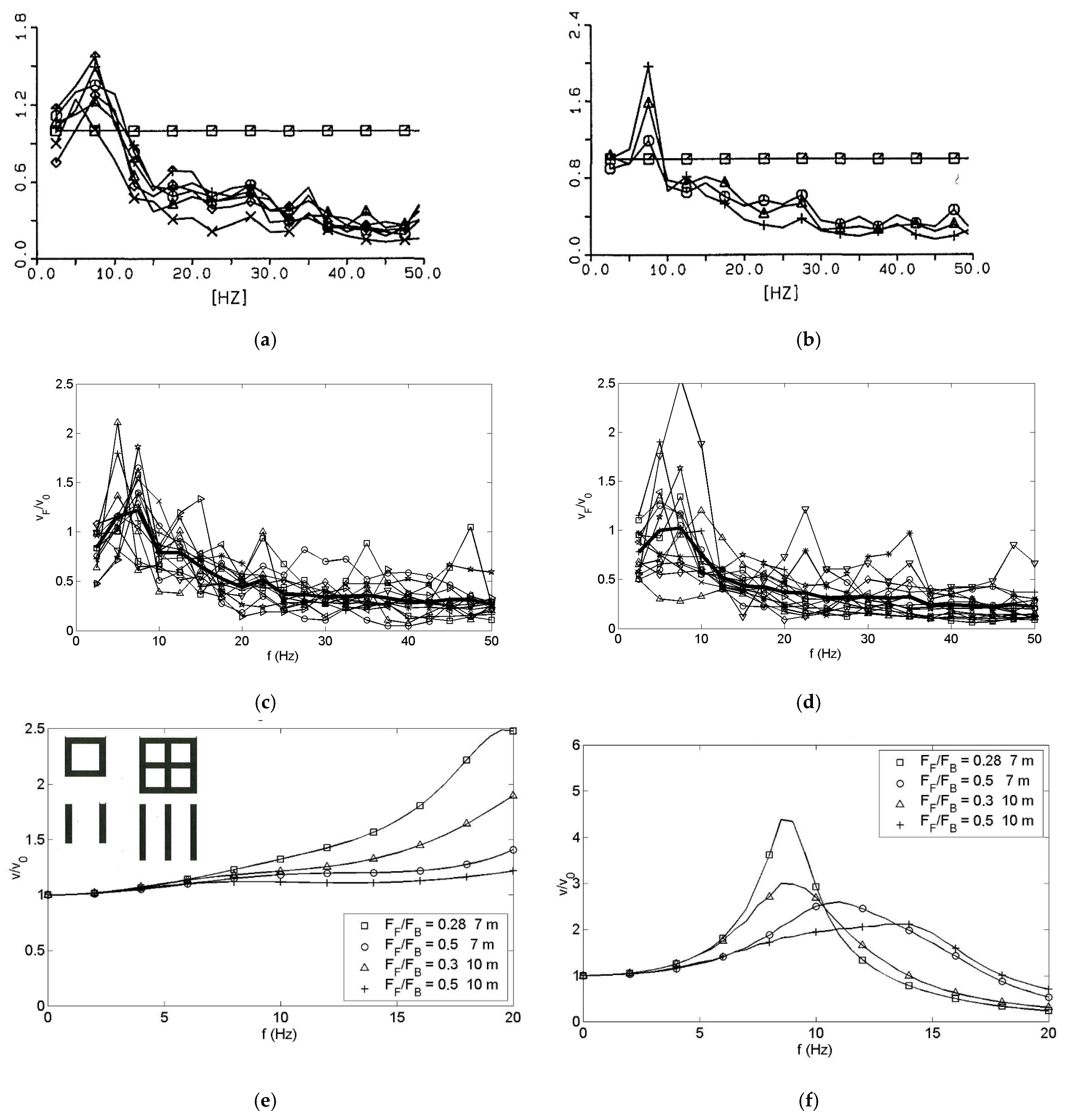
Several small buildings, one- to three-storey residential buildings, have been measured during railway traffic and pile driving excitation. Wave velocities have been measured by hammer impacts in the range of vs = 160–240 m/s for the different sites in and around Berlin. The building response was measured at several measuring points (Figure 15a,b) and the mean value of all foundation points is evaluated for each building to yield the soil–building transfer functions in Figure 15c. The transfer functions show resonances between 5 and 7.5 Hz. For higher frequencies (f > 10 Hz), the amplitudes decrease clearly. A minimum value of 0.1 to 0.3 is reached at 50 Hz. Similar results are obtained for the buildings excited by pile driving (Figure 15d).
The measured resonance frequencies and amplifications in the low-frequency range are compared with FEBEM calculations where rigid building masses on the strip and frame foundations of Section 4.3 have been analysed. At first, it turned out that a homogeneous soil model would give the low resonance frequency only with much lower wave velocities than measured (Figure 15e). Moreover, the clear resonance amplifications cannot be reproduced with the strong radiation damping of homogeneous soil. A satisfactory explanation is obtained by thin strip foundations on soil with increasing stiffness with depth or with a soft top layer (Figure 15f). The most important part of the layering is the soft layer near the soil surface, which strongly reduces the foundation stiffness and damping. The results for the inhomogeneous soil with the continuously increasing stiffness in Figure 15f show building–soil resonance frequencies at 8.5 Hz for the frame foundations and at 7 Hz for the strip foundations. The comparison in Figure 15 shows that the inhomogeneous theory can result in building resonance frequencies that are almost as low and resonance amplifications as high as measured. The good agreement between the theory and measurement is obtained by thin strip foundations on soil with increasing stiffness with depth, either continuously increasing or layered.
The measurement results give some additional information. The response of the building example in Figure 15b includes some differences at the resonance frequency between different measurement points, which may be explained by an additional rocking of the building. The rocking damping is lower than the vertical damping and could also explain, to some extent, the higher resonance amplitudes. The other building example (Figure 15a), however, shows no rocking component. In all measurements, the transfer functions seem to reach a minimum value at 50 Hz. At these high frequencies, the damping of the soil is dominating and the ratio of the soil to the building impedance determine the maximum reduction of the freefield amplitudes. Thus, the radiation damping into the soil rules the resonance amplification as well as the high-frequency reduction in ground-induced building vibrations.

7.3. Floor Resonances and Soil–Structure Interaction

Floor resonances are of great importance for the serviceability of buildings and are the main task in the prediction of railway vibration. It has been found that the foundation damping can have an influence on the floor resonances. Many floors have been measured in several buildings under heeldrop and hammer excitation. Figure 16 shows an example approximation of the transfer function for two concrete floors in a six-storey residential building. The damping values of D = 2.8 and 4.1% at the resonant frequencies f0 = 33 and 45 Hz are higher than the material damping of concrete and are quite probably influenced by the radiation damping into the soil. The results of many floor measurements are summarised in Figure 17. Figure 17a presents the fundamental period T = 1/f0 as a function of the floor area. There are two linear relations for concrete and wooden floors. The period of the wooden floors is approximately twice as long as for the concrete floors. Damping values are measured in the range of 1 to 10%, with most of the values lying between 2 and 4% (Figure 17b). A slight tendency is observed where floors in higher buildings and in higher storeys have less damping. This could indicate that the radiation into the soil contributes considerably to the damping of the floor resonances.
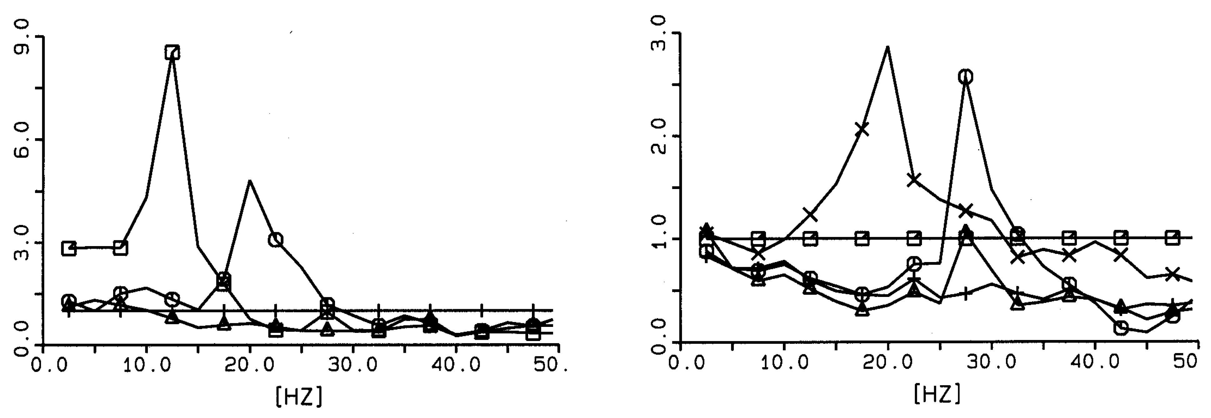
External loads such as passing trains cause soil vibration, and waves travel through the soil and excite neighbouring buildings. The vibration amplitudes of the building can be reduced—as for the foundation—or amplified—as for the floors—compared to the free-field amplitudes of the soil; see Figure 18 for two three-storey residential building examples. The maxima of the floor–soil transfer functions have been evaluated for a number of buildings (Figure 19). The measured amplifications are in the range of 1 to 10 where the highest values are from small one- to three-storey residential buildings and the amplification increases with the natural period of the floor. These amplification values are quite probably limited by the radiation damping into the soil.
In [11], it is shown that the rules that have been found for the floor–building–soil interaction can also be applied to the resonances of railway bridges. Moreover, in [14], it is demonstrated that the resonances of wind energy towers on monopiles are reduced in frequency and amplitude by the compliance and damping of soft soils.

7.4. Measured and Calculated Compliances of Different Railway Tracks

Five ballasted railway tracks have been measured under hammer impacts. The frequency-dependent complex compliances of the rail and the sleeper are presented as amplitude and phase in Figure 20a,b. The transfer functions vary considerably from site to site. The static compliances can be as high as 3 × 10⁻⁸ m/N, but 7 × 10⁻⁹ m/N is also possible. The compliances are determined by the stiffness of the soil or the stiffness of the ballast. No resonance amplification occurs up to 150 Hz. A strong drop in the amplitudes can be found at specific frequencies for each site varying from 40 to 120 Hz. The strong drop in amplitudes is accompanied by a strong drop in the phase. This would indicate a strongly damped eigenfrequency of the track–soil system. There is a difference between the rail and the sleeper amplitudes indicating an elastic rail pad between the rail and sleeper. The phase of the sleeper is a little lower (more negative) than the phase of the rail because of the longer travel time from the impact on the rail to the measurement point on the sleeper. All these details can also be found in the theoretical results in Figure 20c,d. To cover the high low-frequency amplitudes, it is necessary that we include a soft contact stiffness between the ballast and sleeper, which is due to the small number of ballast stones which are in contact with the sleeper. Depending on the contact stiffness, different amplitudes and different cut-off frequencies can be observed in agreement with the experimental results. The main characteristic of railway tracks is the strong damping by the radiation into the soil which prevents or hides any possible track–soil resonance.

8. Conclusions

The damping and stiffness of several rigid and flexible foundations and foundation groups on homogeneous or layered soil have been calculated by the finite-element boundary element method. These are the effects:
  • The basic model of a rigid disc or square foundation on a homogeneous soil has an almost constant stiffness and an almost constant damping which is due to the radiation into the soil and which behaves like a viscous damper.
  • The translational stiffness is proportional to the stiffness of the soil and to the radius of the foundation, and the damping is proportional to the wave impedance and the area of the foundation.
  • For the rotational-degrees-of-freedom rocking and torsion, the stiffness has a stronger dependency on the radius k~r3 and the damping c~r4. The low-frequency damping of the rotations is zero.
  • The damping is dominating the dynamic stiffness or compliance from a certain frequency on which it is lower for softer soils.
  • Groups of foundations approach limit values with some oscillations which are proportional to the total area of the foundation. At low frequencies, foundation groups have a lower stiffness and a much higher damping c~k2.
  • Layered soils have a lower radiation damping up to the horizontal resp. vertical layer frequency.
  • The strong effect of a thin top layer has been found for residential buildings in theory and measurement.
  • Flexible foundations like beams, plates, piles, and tracks have a smaller damping than rigid foundations of the same size.
  • The damping of flexible foundations is decreasing with frequency, with the strongest with c~1/√f for the plate foundation. This damping is not well-represented by a viscous damper.
  • The properties of the structure (the bending stiffness B for the plate) replaces a part of the soil stiffness in the soil–structure interaction results.
  • Therefore, the static stiffness of a flexible foundation is less than proportional to the soil stiffness as k~Gp B1−p with 1−p < p < 1, but the soil is still dominant.
  • At higher frequencies, the damping becomes dominant, and the mass of the structure is dominant at the highest frequencies.
  • The high-frequency laws for flexible foundations are different from the laws for rigid foundations. The phase of the dynamic stiffness (the phase delay of the dynamic compliance) is not 90° as for the dominating damping of a rigid foundation and it does not approach 180° when the mass is dominating. The phase delay of the dynamic compliance and, therefore, the damping of flexible foundations is smaller, for example, 45° at mid and 90° at high frequencies for a flexible plate.
Finally, applications and measurements show the important influence of the damping on the vibrations of railway tracks, rigid blocks, and buildings, which are completely ruled by the soil–structure interaction, and on the vibrations of flexible structures as floors, railway bridges and wind towers, wind energy towers, and railway tracks, which have limited resonance amplitudes due to the radiation damping into the soil.

Funding

This research received no external funding.

Data Availability Statement

The data are in the plots or in sequential files not publicly available.

Conflicts of Interest

The author declares no conflict of interest.

References

  1. Kausel, E. Early history of soil-structure interaction. Soil Dyn. Earthq. Eng. 2010, 30, 822–832. [Google Scholar] [CrossRef]
  2. Roesset, J. Soil structure interaction: The early stages. Appl. Sci. Eng. 2013, 16, 1–8. [Google Scholar]
  3. Richard, F.; Hall, J.; Woods, R. Vibrations of Soils and Foundations; Prentice-Hall: Englewood Cliffs, NJ, USA, 1970. [Google Scholar]
  4. Luco, J. Impedance functions for a rigid foundation on a layered medium. Nucl. Eng. Des. 1974, 31, 204–217. [Google Scholar] [CrossRef]
  5. Gazetas, G. Analysis of machine foundation vibrations: State of the art. Soil Dyn. Earthq. Eng. 1983, 2, 2–42. [Google Scholar] [CrossRef]
  6. Wolf, J. Dynamic Soil-Structure Interaction; Prentice-Hall: Englewood Cliffs, NJ, USA, 1985. [Google Scholar]
  7. Todorovska, M.; Trifunac, M. The system damping and system frequency and the system response peak amplitudes during in-plane building-soil interaction. Earthq. Eng. Struct. Dyn. 1992, 21, 127–144. [Google Scholar] [CrossRef]
  8. Auersch, L. Building response due to ground vibration—Simple prediction model based on experience with detailed models and measurements. Int. J. Acoust. Vib. 2010, 15, 101–112. [Google Scholar] [CrossRef]
  9. Cruz, C.; Miranda, E. Evaluation of soil-structure interaction effects on the damping ratios of buildings subjected to earthquakes. Soil Dyn. Earthq. Eng. 2017, 100, 183–195. [Google Scholar] [CrossRef]
  10. Domenech, A.; Martinez-Rodrigo, M.; Romero, A.; Galvin, P. Soil-structure interaction effects on the resonant response of railway bridges under high-speed traffic. Int. J. Rail Transp. 2015, 3, 201–214. [Google Scholar] [CrossRef]
  11. Heiland, T.; Aji, H.; Wuttke, F.; Stempniewski, L.; Stark, A. Influence of soil-structure interaction on the dynamic characteristics of railroad frame bridges. Soil Dyn. Earthq. Eng. 2023, 167, 107800. [Google Scholar] [CrossRef]
  12. Shadlou, M.; Bhattacharya, S. Dynamic stiffness of monopiles supporting offshore wind turbine generators. Soil Dyn. Earthq. Eng. 2016, 88, 15–32. [Google Scholar] [CrossRef]
  13. Alamo, G.; Aznarez, J.; Padron, L.; Martinez-Castro, A.; Gallego, R.; Maeso, O. Dynamic soil-structure interaction in offshore wind turbines on monopiles in layered seabed based on real data. Ocean Eng. 2018, 156, 14–24. [Google Scholar] [CrossRef]
  14. Auersch, L. Compliance and damping of piles for wind tower foundation in nonhomogeneous soils by the finite-element boundary-element method. Soil Dyn. Earthq. Eng. 2019, 120, 228–244. [Google Scholar] [CrossRef]
  15. Ju, S. Finite element analysis of structure borne vibration from high-speed train. Soil Dyn. Earthq. Eng. 2007, 27, 259–273. [Google Scholar] [CrossRef]
  16. Takemiya, H.; Bian, X. Substructure simulation of inhomogeneous track and layered ground dynamic interaction under train passage. J. Eng. Mech. ASCE 2005, 131, 699–711. [Google Scholar] [CrossRef]
  17. Hussein, M.; Hunt, H.; Kuo, K.; Alves Costa, P.; Barbosa, J. The use of sub-modelling technique to calculate vibration in buildings from underground railways. J. Rail Rapid Transit 2015, 229, 303–314. [Google Scholar] [CrossRef]
  18. Jean, P.; Guigou, C.; Villot, M. A 2.5D BEM model for ground structure interaction. Build. Acoust. 2004, 11, 157–173. [Google Scholar] [CrossRef]
  19. Aji, H.; Wuttke, F.; Dineva, P. 3D structure-soil-structure interaction in an arbitrary layered half-space. Soil Dyn. Earthq. Eng. 2022, 159, 107352. [Google Scholar] [CrossRef]
  20. Colaco, A.; Alves Costa, P.; Amado-Mendes, P.; Calcada, R. Vibrations induced by railway traffic in buildings: Experimental validation of a sub-structuring methodology based on 2.5D FEM-MFS and 3D FEM. Eng. Struct. 2021, 240, 112381. [Google Scholar] [CrossRef]
  21. Liravi, H.; Arcos, R.; Clot, A.; Conto, K.; Romeu, J. A 2.5D coupled FEM-SBM methodology for soils-structure dynamic interaction problems. Eng. Struct. 2022, 250, 113371. [Google Scholar] [CrossRef]
  22. Auersch, L. Wechselwirkung Starrer und Flexibler Strukturen mit dem Baugrund Insbesondere bei Anregung durch Bodenerschütterungen. Ph.D. Thesis, BAM Berlin, Ruhr-University Bochum, Berlin, Bochum, Germany, 1988. [Google Scholar]
  23. Aubry, D. Sur une approche intégrée de l’interaction sismique sol-structure. Rev. Française De Géotechnique 1986, 38, 5–24. [Google Scholar] [CrossRef]
  24. Gaitanaros, A.; Karabalis, D. Dynamic analysis of 3-D flexible embedded foundations by a frequency domain BEM-FEM. Earthq. Eng. Struct. Dyn. 1988, 16, 653–674. [Google Scholar] [CrossRef]
  25. Dangla, P. Couplage Éléments Finis-Équations Intégrales en Élastodynamique et Interaction Sol-Structure. Ph.D. Thesis, ENPC Paris, Paris, France, 1989. [Google Scholar]
  26. Clouteau, D.; Cottereau, R.; Lombaert, G. Dynamics of structures coupled with elastic media—A review of numerical models and methods. J. Sound Vib. 2013, 332, 2415–2436. [Google Scholar] [CrossRef]
  27. Auersch, L. Zur Dynamik einer unendlichen Platte auf dem Halbraum—Fundamentnachgiebigkeit und Wellenfeld bei harmonischer Punktlast. Arch. Appl. Mech. 1994, 64, 346–356. [Google Scholar] [CrossRef]
  28. Auersch, L. Dynamic interaction of various beams with the underlying soil—Finite and infinite, half-space and Winkler models. Eur. J. Mech. A/Solids 2008, 27, 933–958. [Google Scholar] [CrossRef]
  29. Rücker, W.; Auersch, L.; Baeßler, M.; Knothe, K.; Wu, Y.; Popp, K.; Kruse, H.; Savidis, S.; Hirschauer, R.; Bode, C.; et al. A comparative study of results from numerical track-subsoil calculations. In Lecture Notes in Applied Mechanics “System Dynamics and Long-Term Behaviour of Railway Vehicles, Track and Subgrade”; Popp, K., Schiehlen, W., Eds.; Springer: Berlin, Germany, 2003; pp. 471–488. [Google Scholar]
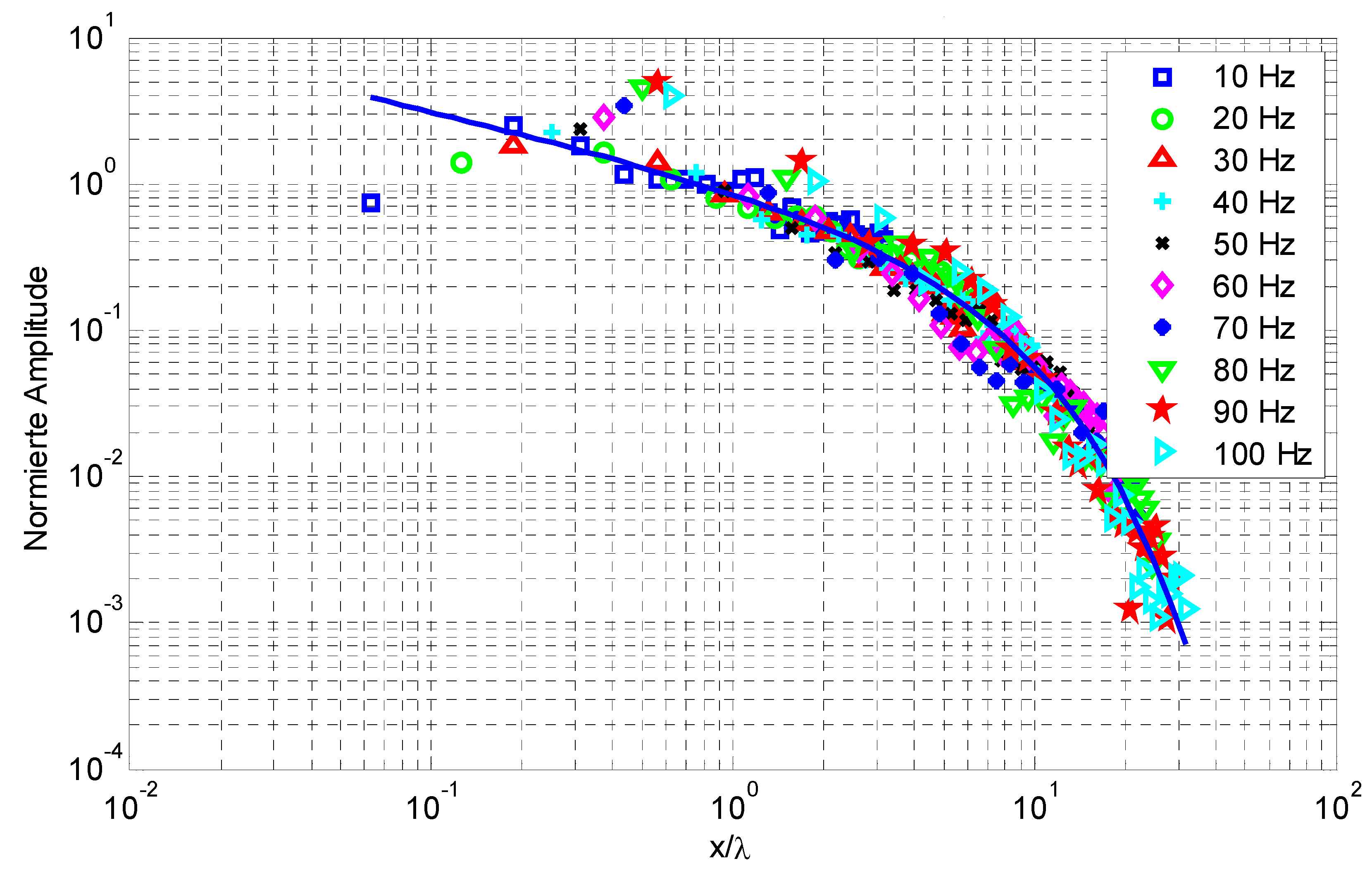
Figure 1. Normalised amplitude–distance law of different frequencies 10, 20, …, 100 Hz and the evaluation of the material damping from their approximation with D = 0.027, q = 0.5, and v = 160 m/s.
Vibration 08 00005 g001
Figure 2. Measured and approximated transfer function v/F, amplitude (top), and complex plane (bottom), for first and second bending mode of a steel beam in laboratory with f1 = 7.9 Hz and f2 = 29 Hz and D = 0.28 and 0.27%.
Vibration 08 00005 g002
Figure 3. Normalised stiffness and damping of a square foundation (2a × 2a) on homogeneous soil ☐, and on a layer over a stiffer half-space, h/a = 1, vS2/vS1 = ◯ 1, △ 2, + 3, and ✕ 5: (a) vertical, (b) horizontal, (c) torsional, and (d) rocking mode.
Vibration 08 00005 g003
Figure 4. Normalised stiffness and damping of a square foundation (2a × 2a) on thick layers, vS2/vS1 = 2, h/a = ☐ 1, ◯ 2, △ 4, and + ∞ (half-space): (a) vertical, and (b) horizontal mode.
Vibration 08 00005 g004
Figure 5. Normalised stiffness and damping of a square foundation (2a × 2a) on thin layers, vS2/vS1 =2, h/a = ☐ ∞ (soft half-space), ◯ 1, △ 0.4, + 0.2, and ✕ 0 (stiff half-space): (a) vertical, and (b) horizontal mode.
Vibration 08 00005 g005
Figure 7. Frequency-dependent stiffness k and damping c of single, strip, frame, and plate foundations, FB = 10 m × 10 m: (a) homogeneous soil with vs. = 200 m/s, and (b) soil with a soft top layer (h = 1 m, vS1 = 70 m/s).
Vibration 08 00005 g007
Figure 8. Low-frequency stiffness k and damping c of different foundations as a function of RF/RB, compared with the values kF and cF of an equivalent disc foundation (a,c) or kB and cB of a foundation with the total building area (b,d).
Vibration 08 00005 g008
Figure 9. Deformation of flexible foundations, a 5 m × 5 m-wide and 0.25 m-thick concrete plate on a soil with vs. = 200 m/s at f = (a) 0 Hz, (b) 25 Hz, (c) 50 Hz, and (d) 75 Hz; real and imaginary part of the transversal deformation of (e,f) a 10 m-long concrete beam of 0.5 m × 0.5 m cross section, and (g,h) a 10 m-long concrete pile of 1 m diameter, at f = ☐ 0, ◯ 25, △ 50, + 75, and ✕ 100 Hz; and (i) a railway track at 100 Hz.
Vibration 08 00005 g009
Figure 10. Frequency-dependent stiffness and damping of a railway track on different homogeneous soils, shear wave velocity vs. = ☐ 100, ◯ 150, △ 200, and + 300 m/s.
Vibration 08 00005 g010
Figure 11. Frequency-dependent stiffness and damping of 10 m-long and 1 m-thick piles in a soil with vs = 200 m/s, for different pile materials, E = ☐ 1, ◯ 2, △ 4, + 8, ✕ 16, ◇ 32, ✴ 64, and ▽ 128 1010 N/m2: (a) vertical, and (b) horizontal component.
Vibration 08 00005 g011
Figure 12. Amplitude and phase of the dynamic compliance of a 10 m-long concrete beam, (a) of 1 m × 1 m cross section on soils with vs = ☐ 100, ◯ 150, △ 200, and + 300 m/s, and (b) on a soil with vs. = 200 m/s for different widths of the contact area a = ☐ 0.1, ◯ 0.3, △ 1, and + 3 m.
Vibration 08 00005 g012
Figure 13. Amplitude and phase of the dynamic compliance of a 5 m × 5 m-wide and 0.25 m-thick plate on soils with vs. = ☐ 100, ◯ 150, △ 200, and + 300 m/s: (a) rigid plate, (b) concrete plate, and (c) plates of different heights h = ☐ 0.15, ◯ 0.25, △ 0.5 m, and + 0.5 m, and rigid.
Vibration 08 00005 g013
Figure 14. Amplitude and phase of the admittances v/F in mm/skN of a 1 m × 1 m × 1 m concrete block on a soft soil (a), excited by vertical or horizontal forces, ☐ calculation and ◯ measurement for the (b) vertical and (c) torsional mode, calculation of the (d) rocking and (e) horizontal mode, and measurement of the (f) rocking and (f,g) horizontal mode.
Vibration 08 00005 g014aVibration 08 00005 g014b
Figure 15. Soil–building transfer functions v/v0 of 2-storey residential buildings, measurements (a,b) all foundation points of two building examples, and (c,d) the mean value of all foundation points for each of the buildings, − the average function of all buildings; calculation of ☐, △ strip and ◯, + frame foundations (e) on a homogeneous soil, and (f) on a soil with increasing stiffness.
Vibration 08 00005 g015
Figure 16. Measured and approximated transfer function, amplitude (top), and complex plane (bottom), for short-span concrete floors in 6-storey residential building with f0 = 33 and 45 Hz and D = 2.8 and 4.1%.
Vibration 08 00005 g016
Figure 17. Eigenfrequencies and damping of several floor measurements: (a) fundamental period of ☐ concrete and ◯ wooden floors as a function of the floor area, and (b) damping as a function of the height in the building.
Vibration 08 00005 g017
Figure 18. Soil–building transfer functions v/v0 of two 3-storey residential buildings, ◯ concrete floors, ☐ resp. ✕ wooden floors, and some foundation points.
Vibration 08 00005 g018
Figure 19. Floor–soil resonance amplification as a function of the fundamental period.
Vibration 08 00005 g019
Figure 20. Amplitude and phase of the dynamic compliance of five railway tracks: (a,b) measurement for one-rail hammer excitation, (c,d) calculation for two-rail wheelset excitation, (a,c) the rail, and (b,d) the sleeper.
Vibration 08 00005 g020
Disclaimer/Publisher’s Note: The statements, opinions and data contained in all publications are solely those of the individual author(s) and contributor(s) and not of MDPI and/or the editor(s). MDPI and/or the editor(s) disclaim responsibility for any injury to people or property resulting from any ideas, methods, instructions or products referred to in the content.