3.1. Constant-Current Sine Tests on Preliminary Compressor Prototype
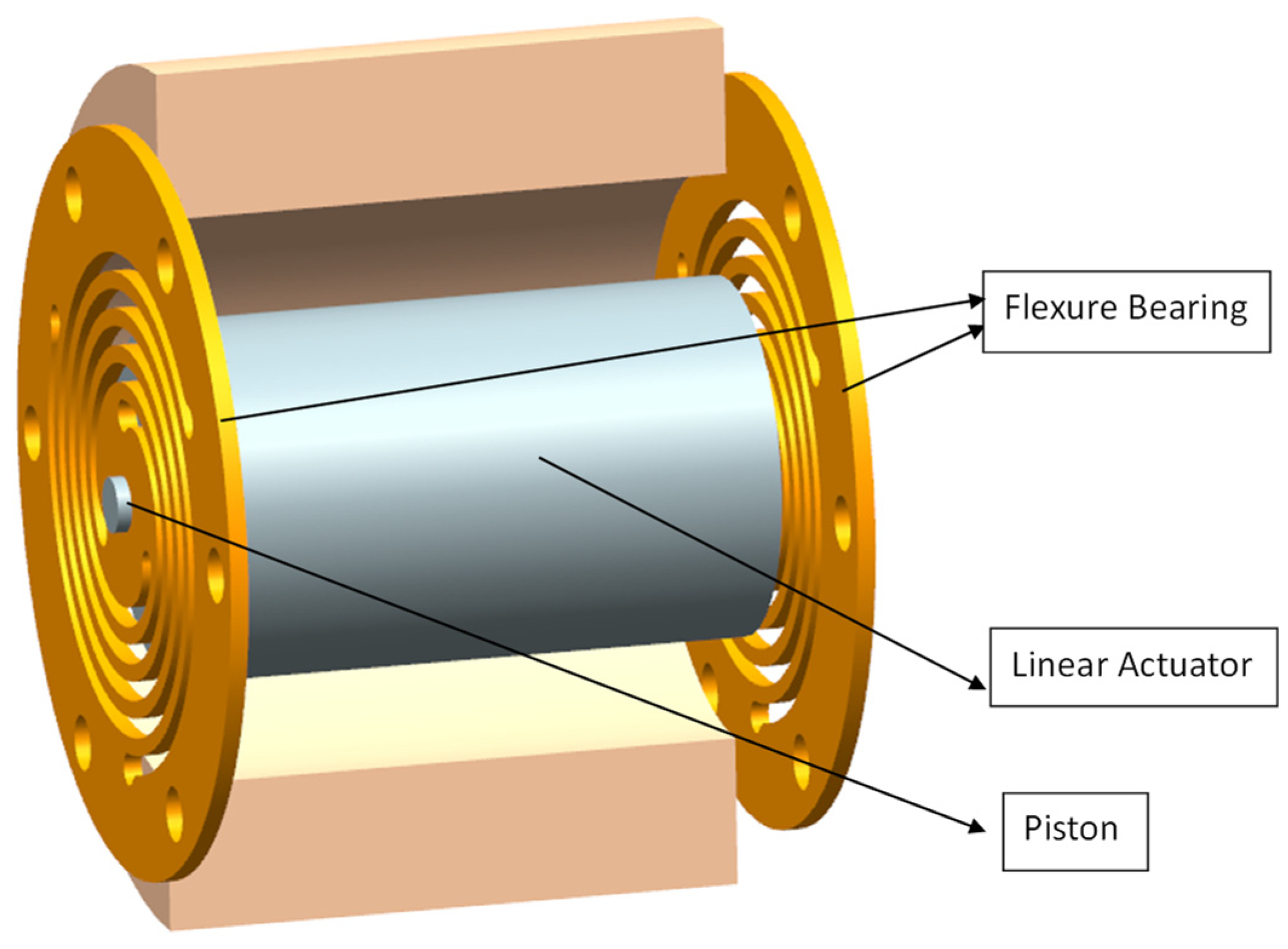
The experimental design procedure proposed in this paper for flexure-based Stirling cryocooler compressors starts with a series of open-loop constant-amplitude harmonic current tests conducted on a preliminary compressor design. The schematic view of the preliminary design is shown in
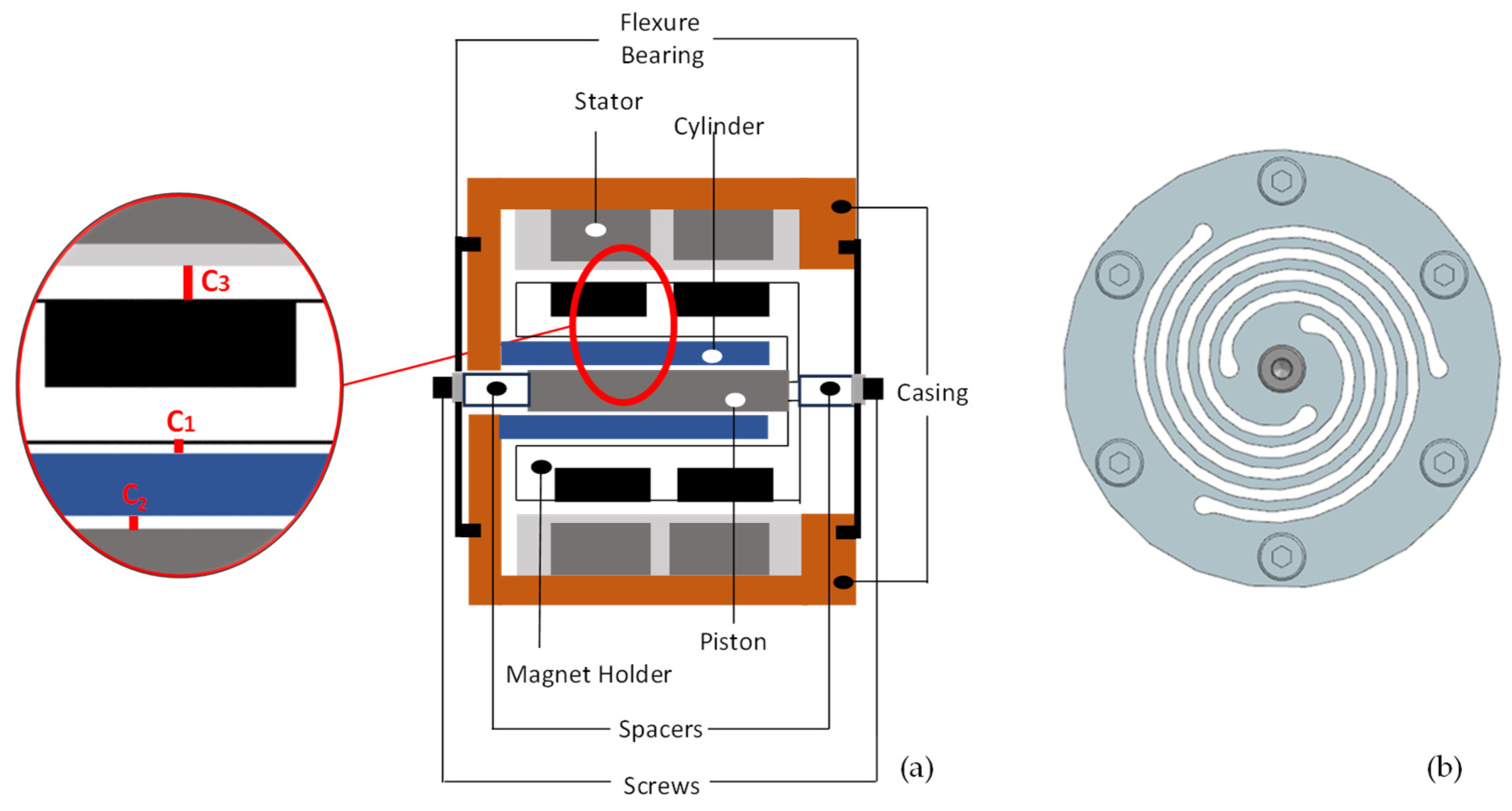
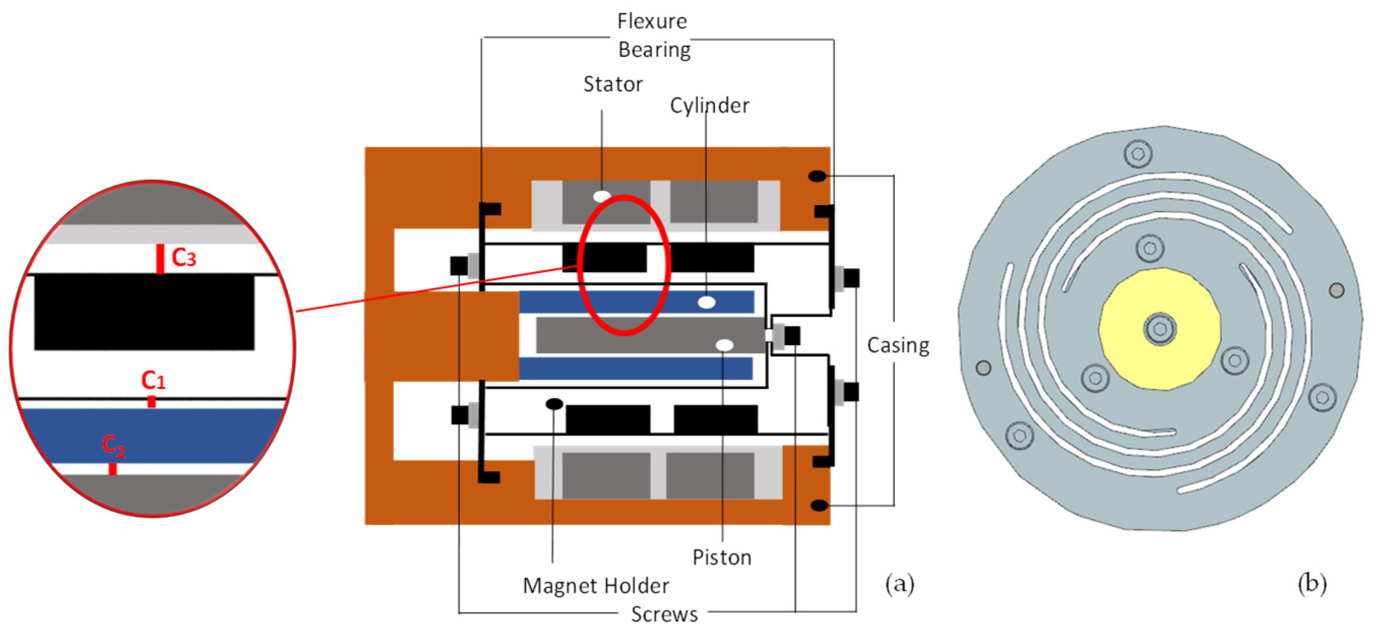
Figure 3. The piston/magnet holder assembly is supported by flexure bearings. The axial harmonic motion of this assembly is achieved by the stator that drives the magnets in the magnet holder. This type of design is called a Stirling cryocooler with moving magnets. The stator and the cylinder component (shown in blue in
Figure 3) are fixed to the chassis of the compressor; i.e., they do not move. As can be seen from the figure, there exist very small gaps in three different regions: between the cylinder and the piston (C
1), between the magnet holder and the cylinder (C
2), and between the stator and the magnet holder (C
3). These gaps should be kept small in order to minimize the working gas leakage to the backside of the piston, which reduces pressure fluctuations and improves the cooling performance.
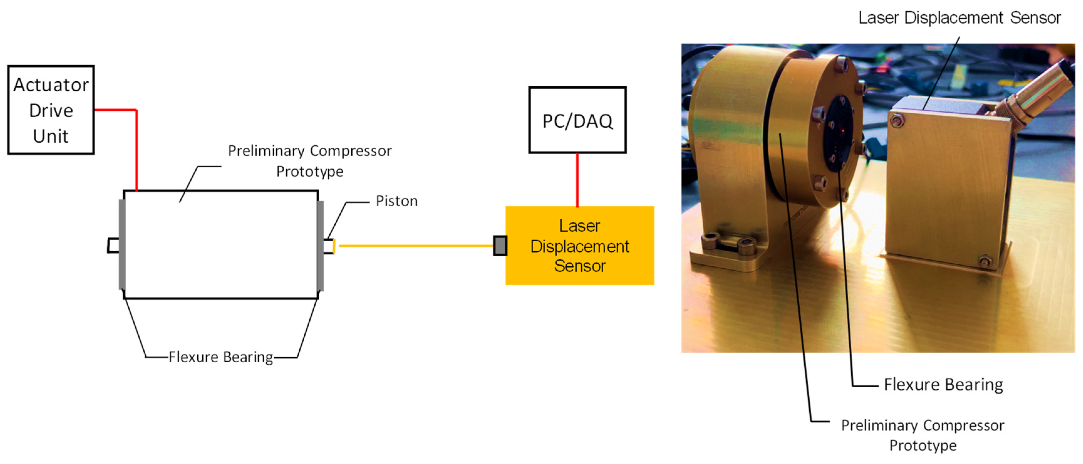
The constant-current sine test setup is shown in
Figure 5. The harmonic current driving the actuator was generated by a Brushless PWM Servo Amplifier (Camarillo, CA, USA). The response of the piston was measured by an Eltrotec Inc. Series LDS 70/10 laser displacement sensor (Padasjoki, Finland)at a sampling rate of 1000 Hz.
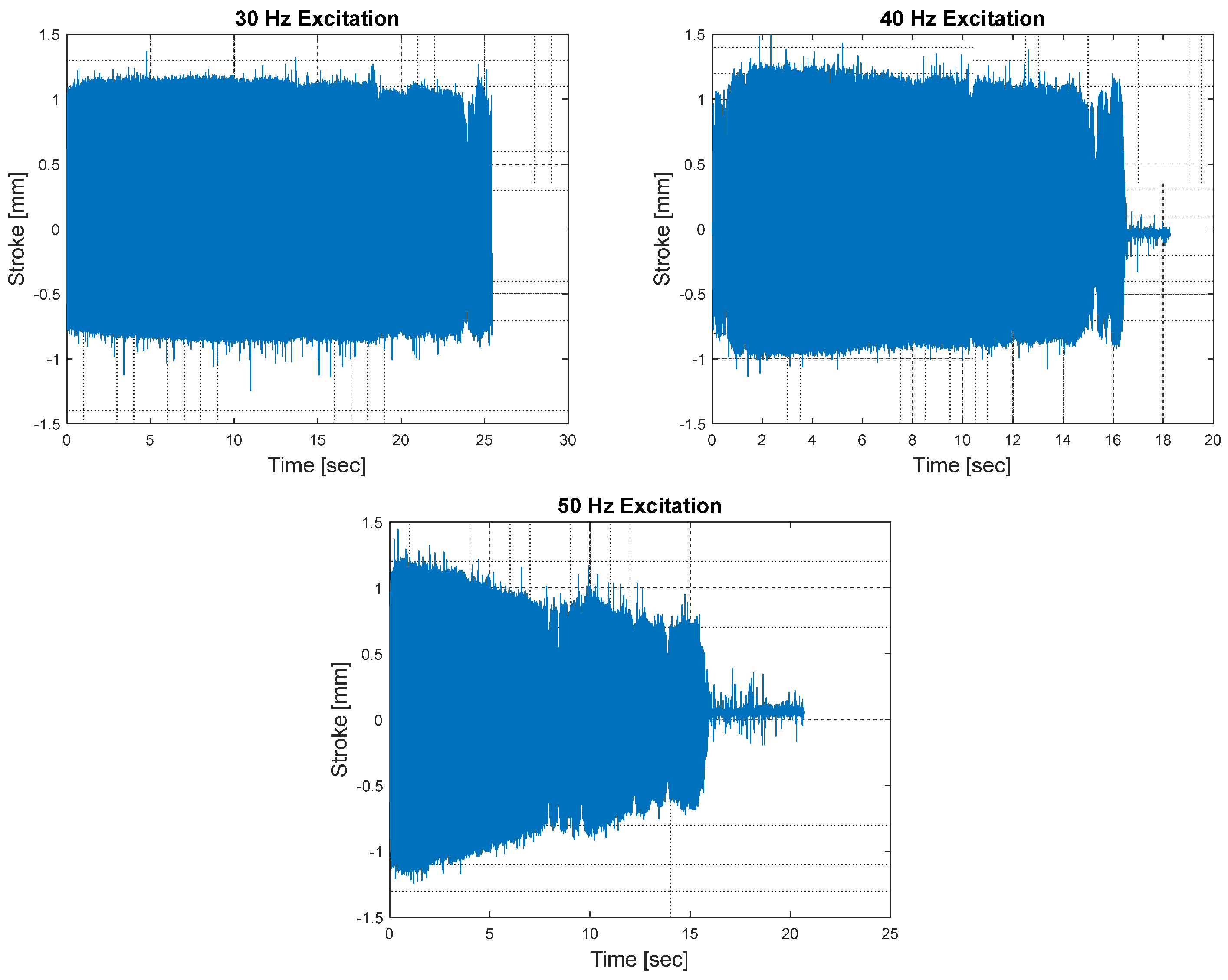
Constant-current tests conducted on the preliminary compressor prototype revealed a severe instability issue: the piston/magnet holder assembly, which was expected to oscillate, steadily stopped all of a sudden during the tests though the current was not cut off. This issue is illustrated at the excitation amplitude level of 1 A at 40 and 50 Hz in
Figure 6, where the harmonic displacement response of the piston suddenly drops to zero. The problem seems to be caused by the piston/magnet holder assembly being pulled into the cylinder/stator assembly and sticking. The pulling effect probably stems from the nonzero net radial magnetic force caused by the non-uniformity of the small gaps (i.e., misalignment) described above. The net magnetic force should be ideally balanced by the radial stiffness of the flexure bearings, which does not seem to be the case in this study.
Considering
Figure 6, it is interesting to note that although the instability issue discussed above does not exist at 30 Hz, it becomes a serious problem at higher frequencies (i.e., 40 and 50 Hz). This is reasonable because the radial stiffness of a flexure bearing, shown in
Figure 3b, is typically very sensitive to its vibration amplitude, as shown in [
25], and there is an inverse correlation between the vibration amplitude and the radial stiffness. In this context, as the excitation frequency nears the resonance frequency of the single-DOF oscillator, which is around 59 Hz, the piston’s displacement amplitude gradually increases. This significantly reduces the radial stiffness of the bearing. Consequently, it cannot balance the net radial magnetic force caused by misalignment anymore and leads to the sticking/locking phenomenon, as discussed above.
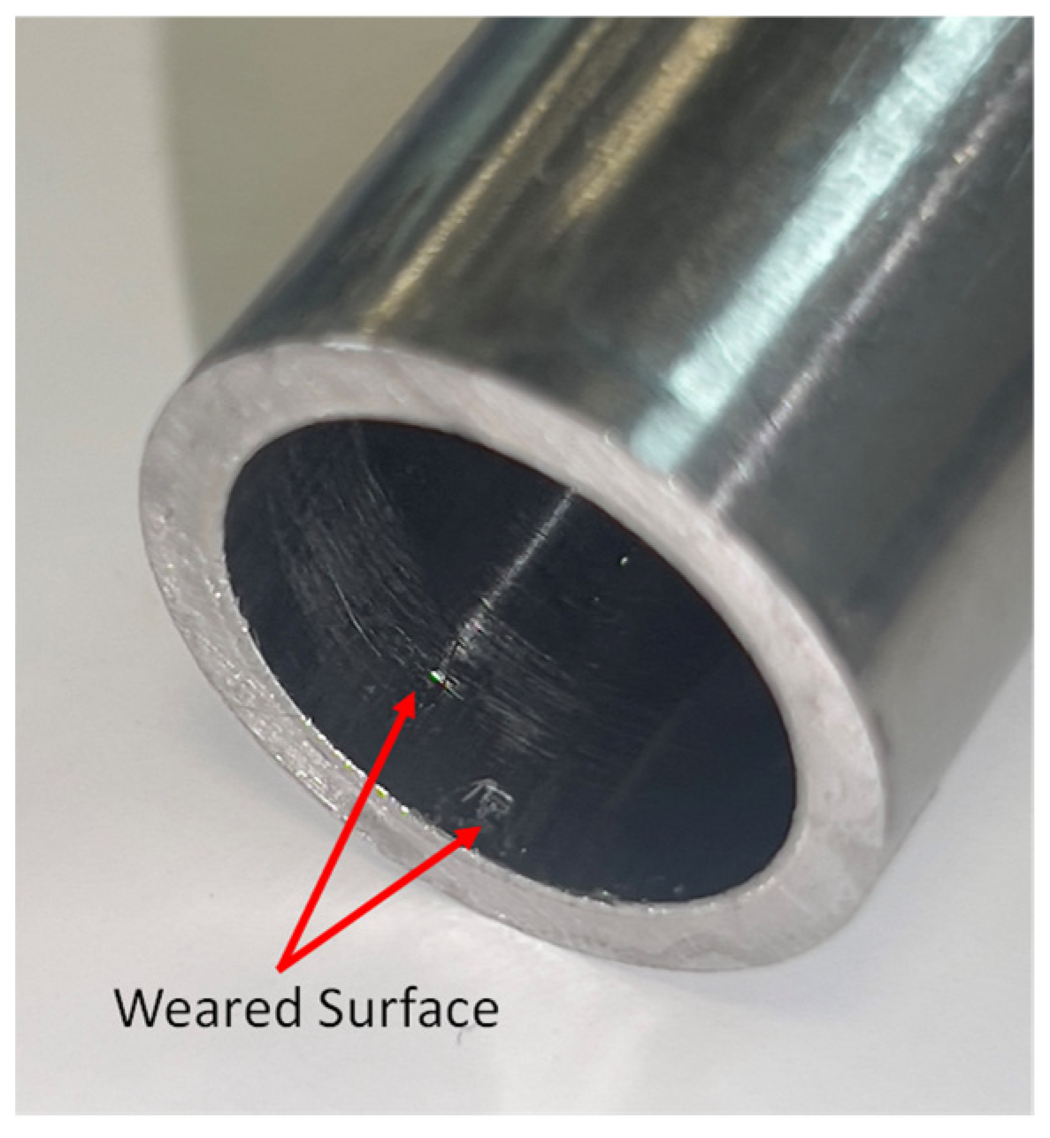
Another interesting observation relevant to the preliminary compressor prototype is the considerable friction-induced wear at the inner face of the magnet holder observed after the disassembly of the prototype, as shown in
Figure 7. This finding points out the occurrence of severe friction between the magnet holder and the cylinder (see
Figure 3) during the motion of the piston/magnet holder assembly before the sticking/locking phenomenon.
3.2. Response-Controlled Tests with Base Excitation on Simplified Compressor Models
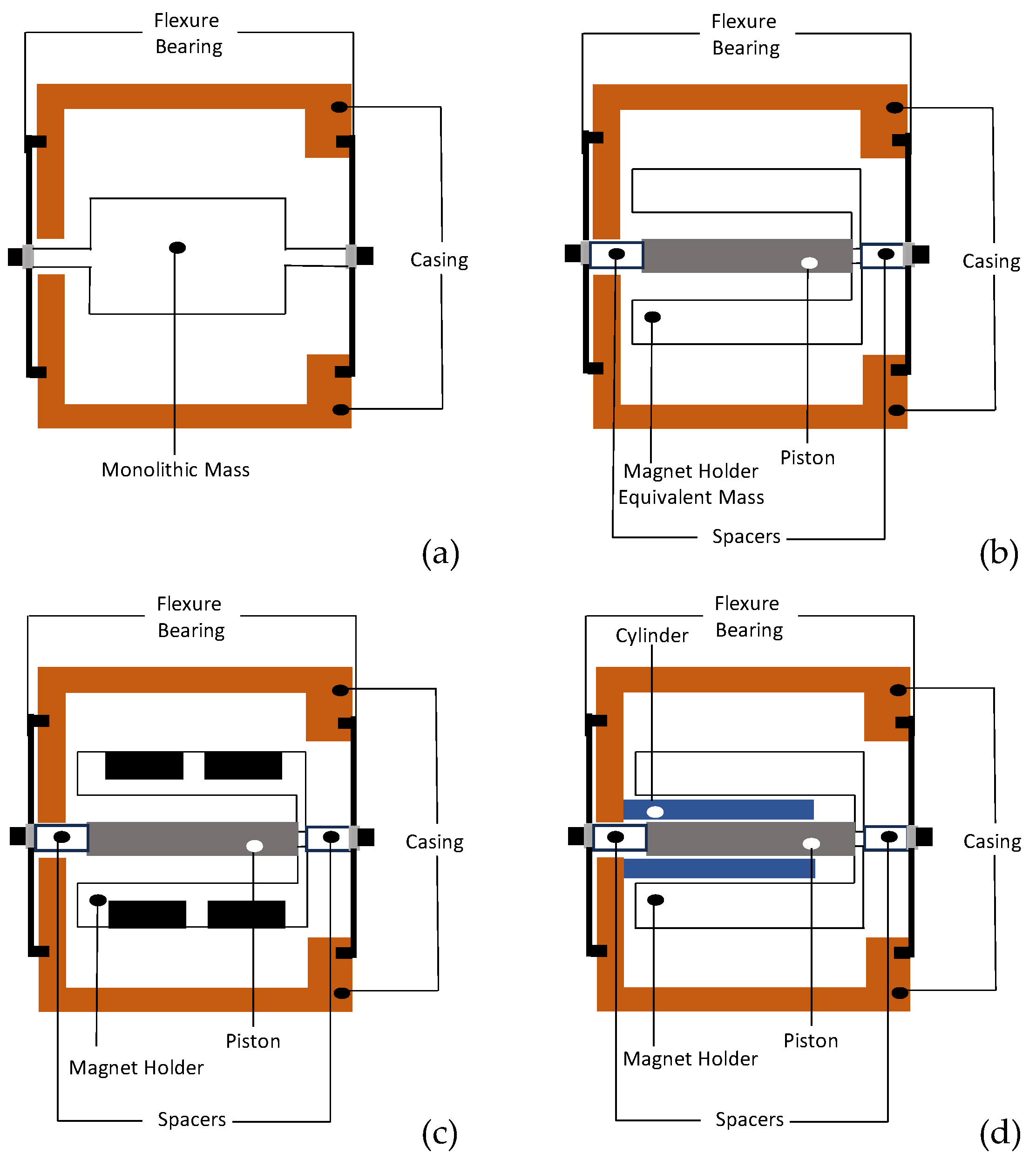
In order to find the root cause of the instability and excessive wear discussed in the previous section, a series of constant-response tests were conducted on four different simplified models of the preliminary compressor design illustrated in
Figure 8. As can be seen from the figure, the simplified models range from System A to System D with gradually increasing complexity.
System A consists of a monolithic mass whose inertia is equivalent to that of the magnet holder and piston assembly. The purpose of this simplified model is to study the degree of nonlinearities exhibited by the stiffness of the flexure bearing and the screw connections. System B includes the original piston, the spacers, and the mass equivalent of the magnet holder/magnet assembly. This system is dedicated to determining the effect of holding multiple parts together mechanically on the nonlinear dynamics. On the other side, System C contains real magnets, which aims to study the effect of magnetic forces on the system dynamics. Finally, System D includes the original cylinder, the original piston, and the mass equivalent version of the magnet holder to study purely the effects of the misalignment on the system dynamics, excluding the contribution of magnetic effects.
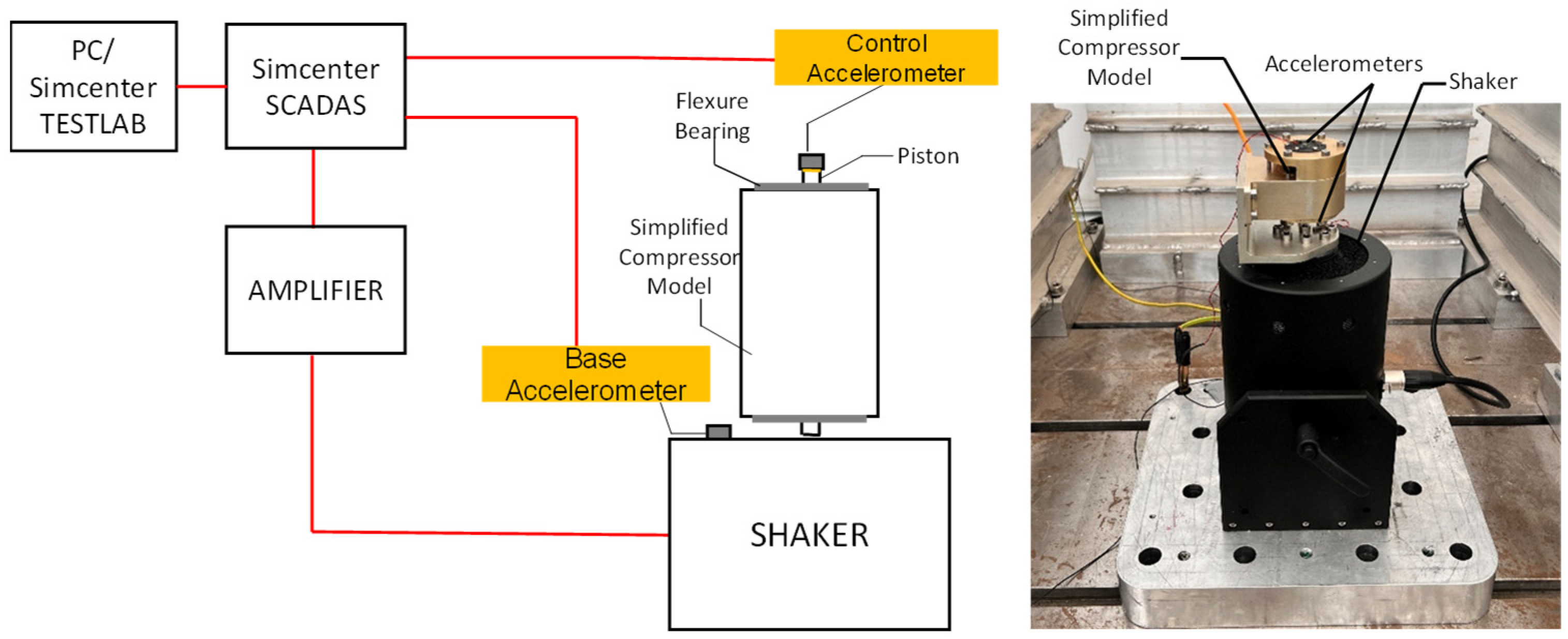
As seen in
Figure 8, the simplified models do not possess an active actuator. Therefore, RCT was necessarily implemented with an external excitation source. Furthermore, since an electrodynamic modal shaker attachment was found to be inappropriate, as explained in detail in
Section 2.2, tests were conducted with base excitation, as illustrated in
Figure 9. As seen from the figure, closed-loop amplitude control was achieved by using Simcenter SADAS Mobile and Simcenter TestLab. (Munich, Germany) A DynaLabs Inc. shaker (DYN-PM-400) (Ankara, Turkey) was used for base excitation.
It is also important to note that since the vertical positioning of the laser displacement sensor was difficult, a miniature accelerometer (PCB 352A73) attached to the piston was used as the control sensor. The slight shift in the resonance frequency due to the additional mass of this accelerometer was tolerable because it did not affect the main purpose of this study. In this configuration, the displacement amplitude is kept constant indirectly by defining an appropriate reference acceleration profile for the controller. The reference accelerometer (PCB 352A73) corresponding to the base DOF is attached to the fixture connecting the compressor to the shaker, as shown in
Figure 9.
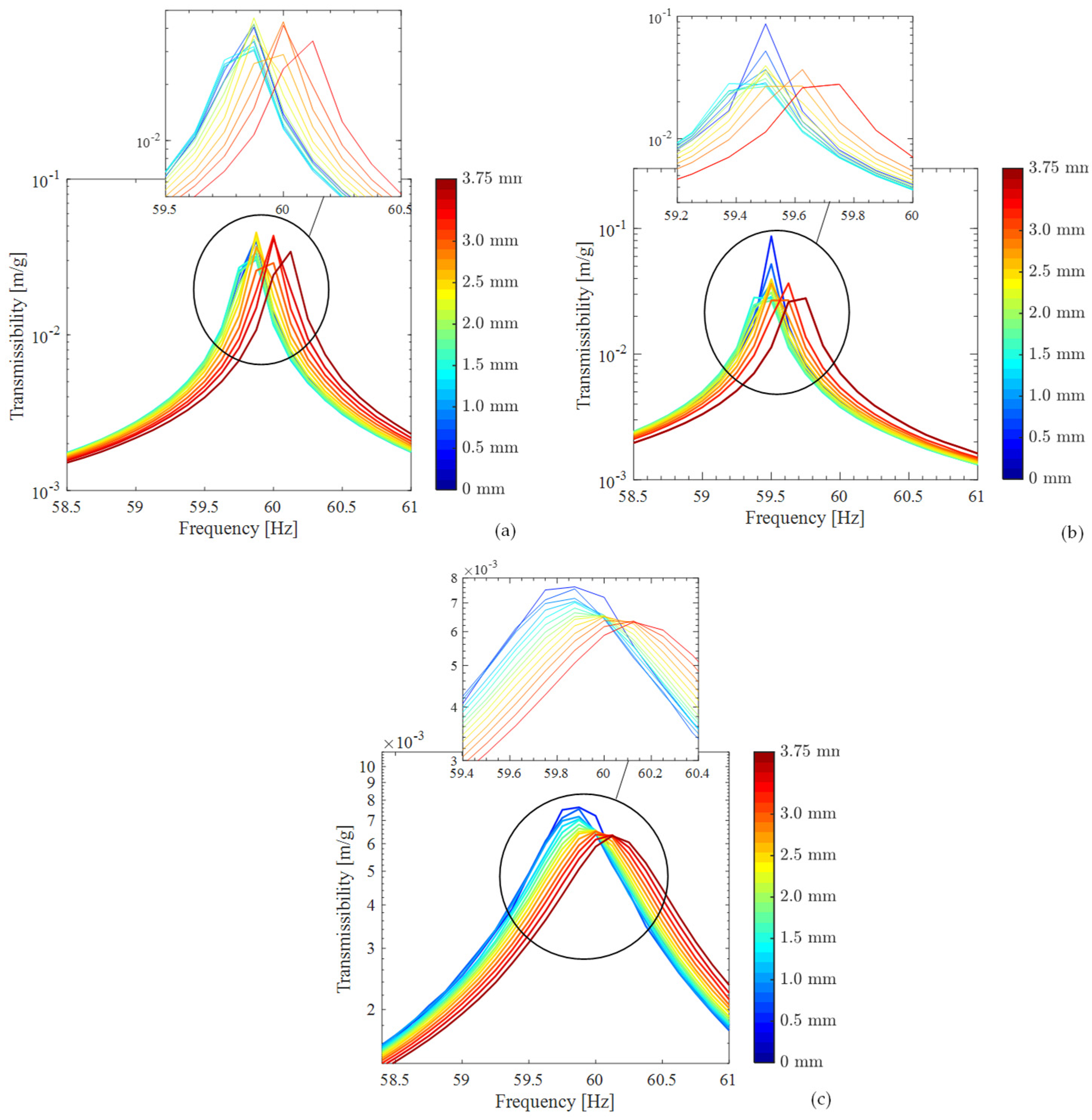
The response-controlled stepped-sine tests were conducted with a fixed frequency range (58.5–61 Hz) and a frequency step size of 0.125 Hz. The quasi-linear FRFs measured at different amplitude levels ranging from 0.5 mm to 3.75 mm for the simplified models, A, B, and C, are shown in
Figure 10. These quasi-linear FRFs were then processed by using a standard linear experimental modal analysis technique, namely, the peak-picking method [
13], to extract the natural frequencies and modal damping ratios.
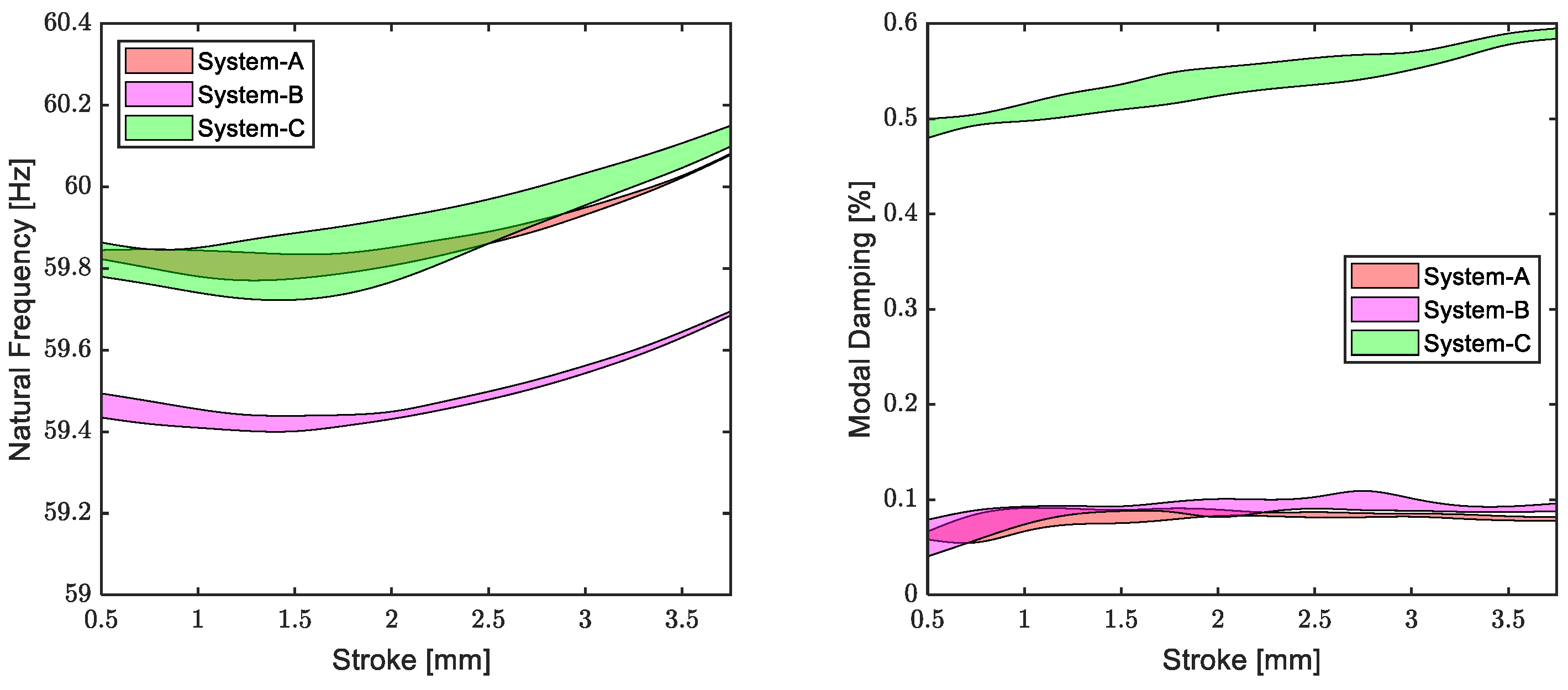
The response-level-dependent nonlinear modal parameters identified by using the peak-picking method for Systems A, B, and C are given in
Figure 11, with the 95% confidence intervals obtained by repeating the tests three times. The first important conclusion that can be drawn from the figure is that the repeatability is good, and the simplified models exhibit weak stiffness and damping nonlinearities in general. The slight increase in the natural frequencies with the increasing response amplitude results from the weak, stiffening nonlinearity of the flexure bearings in the axial direction. In contrast, the modal damping ratio curves of Systems A and B are almost constant. In other words, these systems exhibit insignificant damping nonlinearities. The slightly lower natural frequency of System B stems from the slightly higher inertia values due to the exceeded manufacturing tolerances.
Although the mechanical connections of System C are identical to those of System A and B, its modal damping ratio significantly deviates from those of Systems A and B both in the magnitude and degree of nonlinearity. This can be attributed to the magnetic field generated by the magnets included in System C. It can be concluded that the magnetic field significantly increases both the magnitude and the nonlinearity of the modal damping ratio.
Finally, in order to study the effects of the misalignment on the system dynamics, excluding the contribution of magnetic effects, RCT with base excitation was conducted on System D shown in
Figure 8d. However, a very poor amplitude control performance was observed due to the excessive friction between the components, and the quasi-linear FRFs could not be measured reliably. This finding is a clear indication of poor alignment.
In light of the results discussed above, the design of the flexure bearings was modified as illustrated in
Figure 12 and Figure 14b. In this enhanced design, instead of directly attaching the flexure bearings to the piston with a single-screw connection, they are attached to the magnet holder with three screws.
Fortunately, response-controlled tests with base excitation conducted on the enhanced design shown in
Figure 12 gave very satisfactory results. Precise amplitude control could be achieved. The modal parameters identified for the enhanced design are given in
Figure 13. The results are very similar to those obtained for Systems A and B. The modal damping ratio is very low, and the system exhibits very weak stiffness and damping nonlinearity, which is the ideal case that maximizes the mechanical efficiency and minimizes the energy loss for an acceptable cryocooler performance. It can be concluded that the design modifications provided precise alignment and eliminated contact and friction between the magnet holder, cylinder, and piston, despite the small gaps shown in
Figure 12.
3.3. Nonlinear Experimental Modal Analysis of the Enhanced Compressor Design with the Harmonic Force Surface (HFS) Concept
As demonstrated in the previous section, the new flexure-bearing design shown in
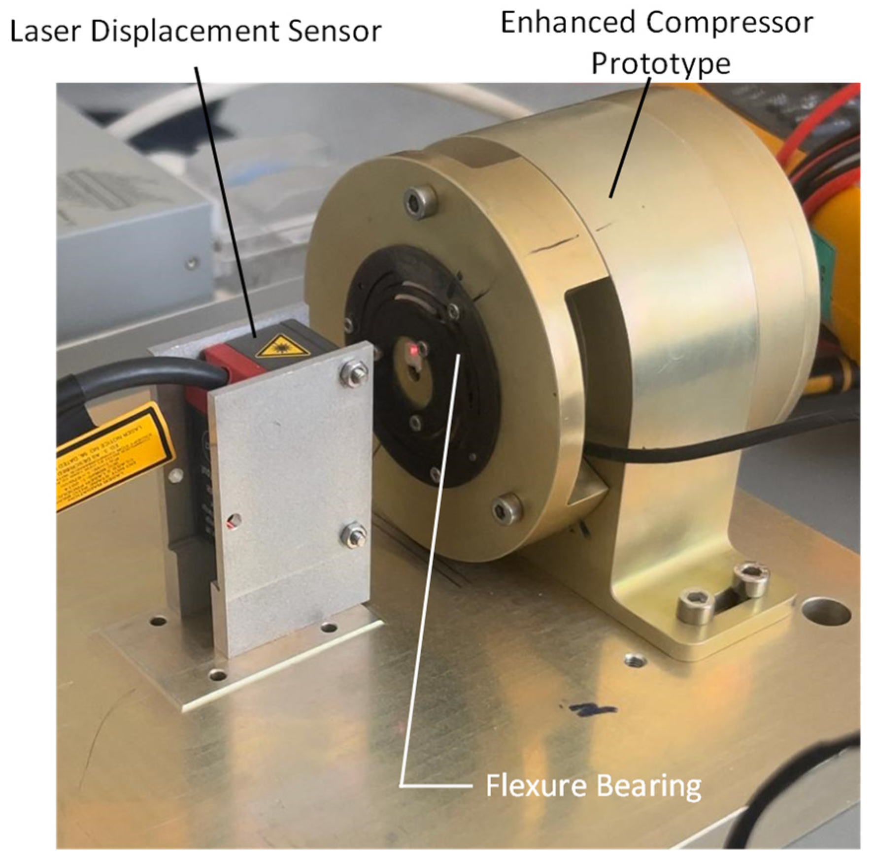
Figure 14b significantly improved the alignment of the components in the absence of electromagnetic forces. In order to test the performance of this new design in the actual compressor, an enhanced compressor prototype, whose schematic is shown in
Figure 14a, was manufactured. In this new prototype, apart from the modification of the fastener configuration, the second important modification is the increase in the radial stiffness of the flexure bearings by increasing their thicknesses. As discussed in
Section 3.1, radial stiffness plays a key role in balancing the net magnetic forces caused by the misalignment of the components. Therefore, this second modification aims to avoid the pulling and sticking of the piston/magnet holder assembly to the cylinder/stator assembly, contrary to the preliminary compressor design (see
Section 3.1).
In order to test the performance of the enhanced design, an experimental setup, which is very similar to that of the preliminary compressor prototype (
Figure 5), was constructed, as shown in
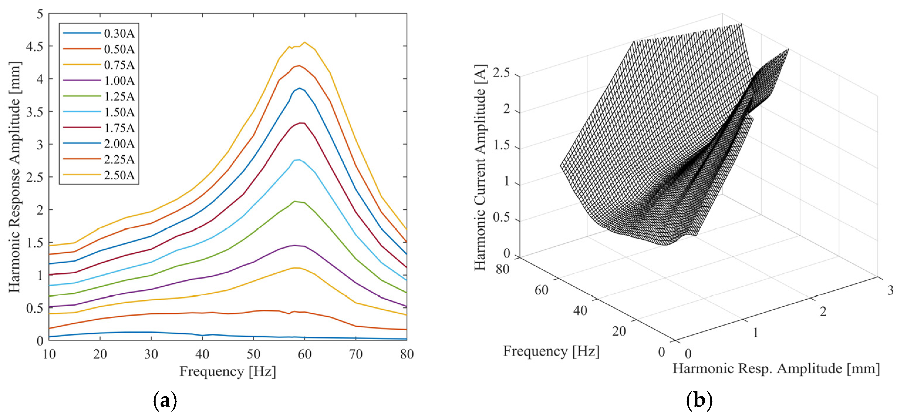
Figure 15. Then, a series of open-loop constant-current tests were conducted at harmonic current amplitude levels ranging from 0.3 A to 2.5 A within a frequency range of 10–80 Hz. Frequency response curves measured from these tests are shown in
Figure 16a. In this application, the sticking/locking phenomenon was not observed, contrary to the preliminary design. At this stage, it can be concluded that the design modifications mentioned above proved to be quite effective. However, there is still one critical question: Are the mechanical losses at an acceptable level for a reasonable compressor performance? The answer to this question requires the identification of the system’s dynamical properties, especially its damping.
Post-processing of the frequency responses given in
Figure 16a indicated that linear analytical models do not accurately represent the system dynamics, especially at low current levels. In this context, response-controlled testing looks suitable for the modal analysis of the enhanced compressor prototype. As explained in
Section 2.3, in the conventional RCT framework, quasi-linear constant-response FRFs are directly measured by keeping the displacement amplitude of a reference point constant in a closed-loop control. These FRFs can then be processed by using standard linear modal analysis techniques to identify the response-level-dependent nonlinear modal parameters. In such a framework, the driving current spectrum takes the form of a V-shape curve that makes a dip at the resonance frequency. In other words, the actuator draws the minimum current (and therefore power) at resonance, which makes sense.
In this application, the conventional RCT method was not preferred for several reasons. Firstly, closed-loop control may be invasive in some cases; i.e., it may affect the actual system dynamics. However, open-loop testing is non-invasive by nature because the system response is not forced to match a reference profile. Secondly, RCT may require excessive current to keep the displacement amplitude constant at frequencies far away from resonance, especially if the system exhibits excessive friction-induced damping. This may lead to the damage of the actuator and/or excessive heat generation causing the severe time variability in the nonlinear dynamics [
17]. Finally, the frequency responses shown in
Figure 16a do not exhibit the jump phenomenon, which makes them very suitable for extracting quasi-linear FRFs by using the HFS-based indirect approach explained in
Section 2.3.
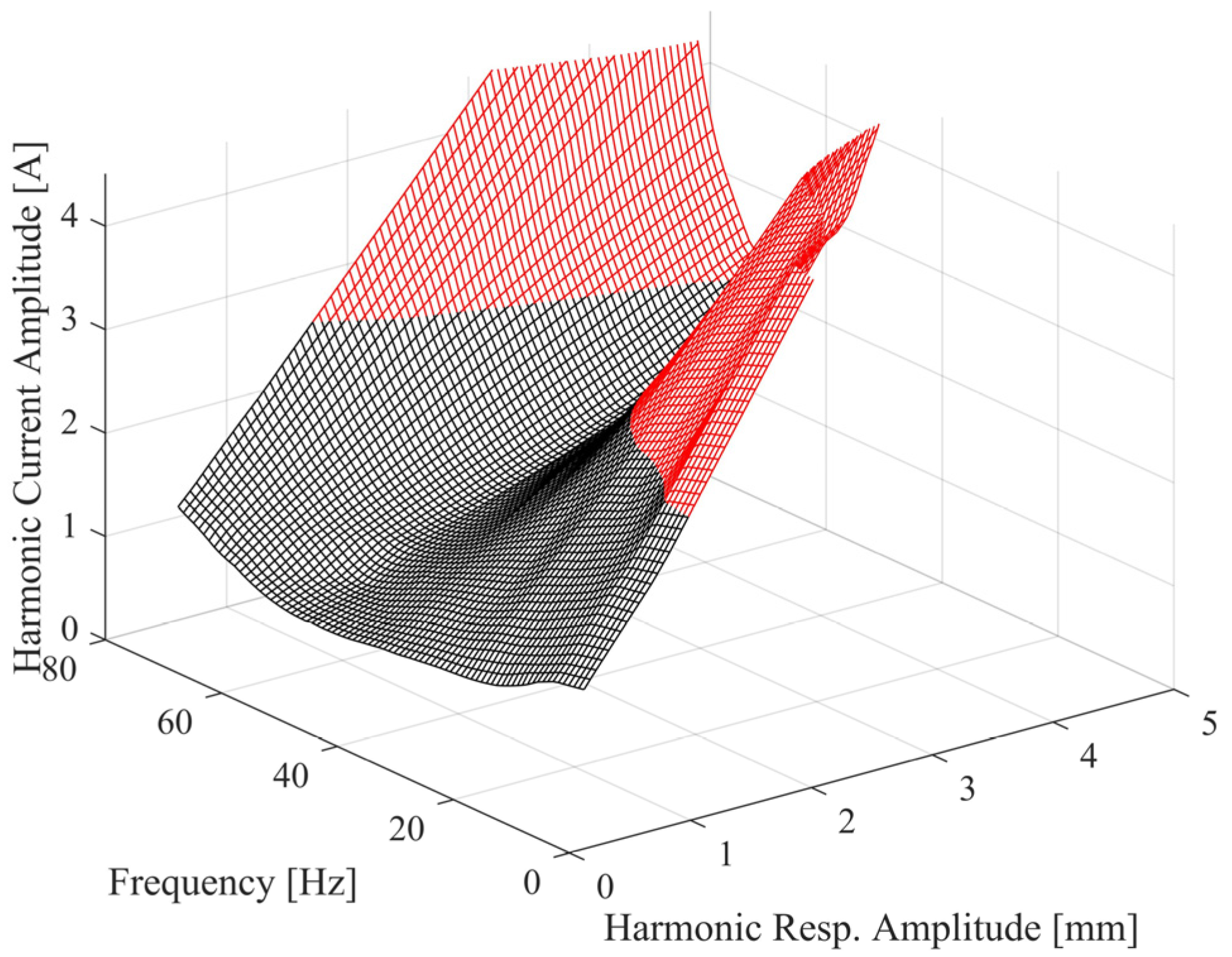
In light of the above discussion, first of all, the constant-current frequency response curves shown in
Figure 16a were combined to construct the HFS, as shown in
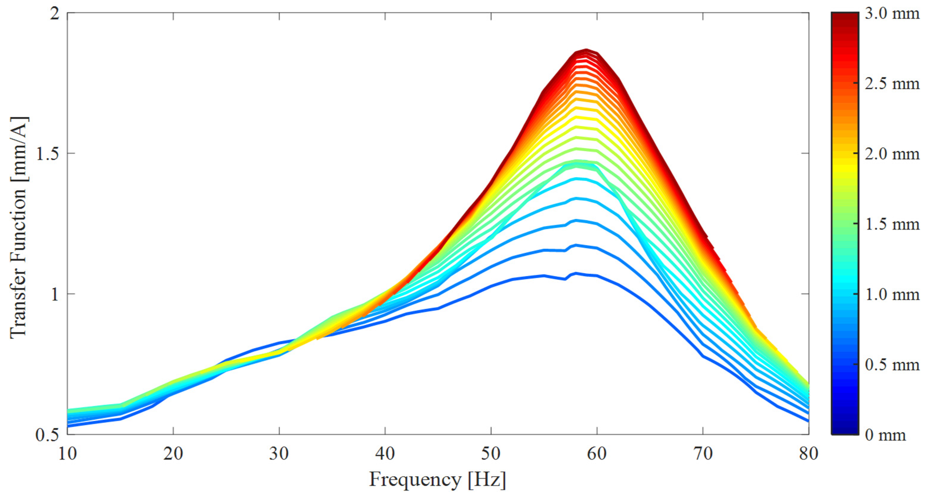
Figure 16b. Cutting the HFS with different constant-displacement amplitude planes gave V-shaped harmonic current spectra. Finally, by dividing each constant-displacement amplitude value with the corresponding V-shaped harmonic current spectrum, quasi-linear constant-response FRFs were obtained, as illustrated in
Figure 17.
According to the single nonlinear mode theory [
13], near-resonant FRFs between the driving current amplitude and the displacement amplitude of the control DOF of the enhanced compressor prototype can be represented analytically as follows:
where
,
, and
are the modal constant, natural frequency, and hysteretic modal damping ratio of the
th nonlinear mode, respectively.
indicates the response coordinate,
is the displacement amplitude of the response coordinate (control DOF), and
represents the excitation frequency.
Equation (1) indicates that all modal parameters are functions of a single independent variable: the displacement amplitude. Therefore, if the displacement amplitude is kept constant throughout the frequency sweep, FRFs come out in the quasi-linear form. In this context, the nonlinear modal identification of the enhanced compressor design is achieved by fitting the analytical model given in Equation (1) to the quasi-linear FRFs shown in
Figure 17. In this study, at each constant-response level, nonlinear modal parameters are identified by using the simple peak-picking method [
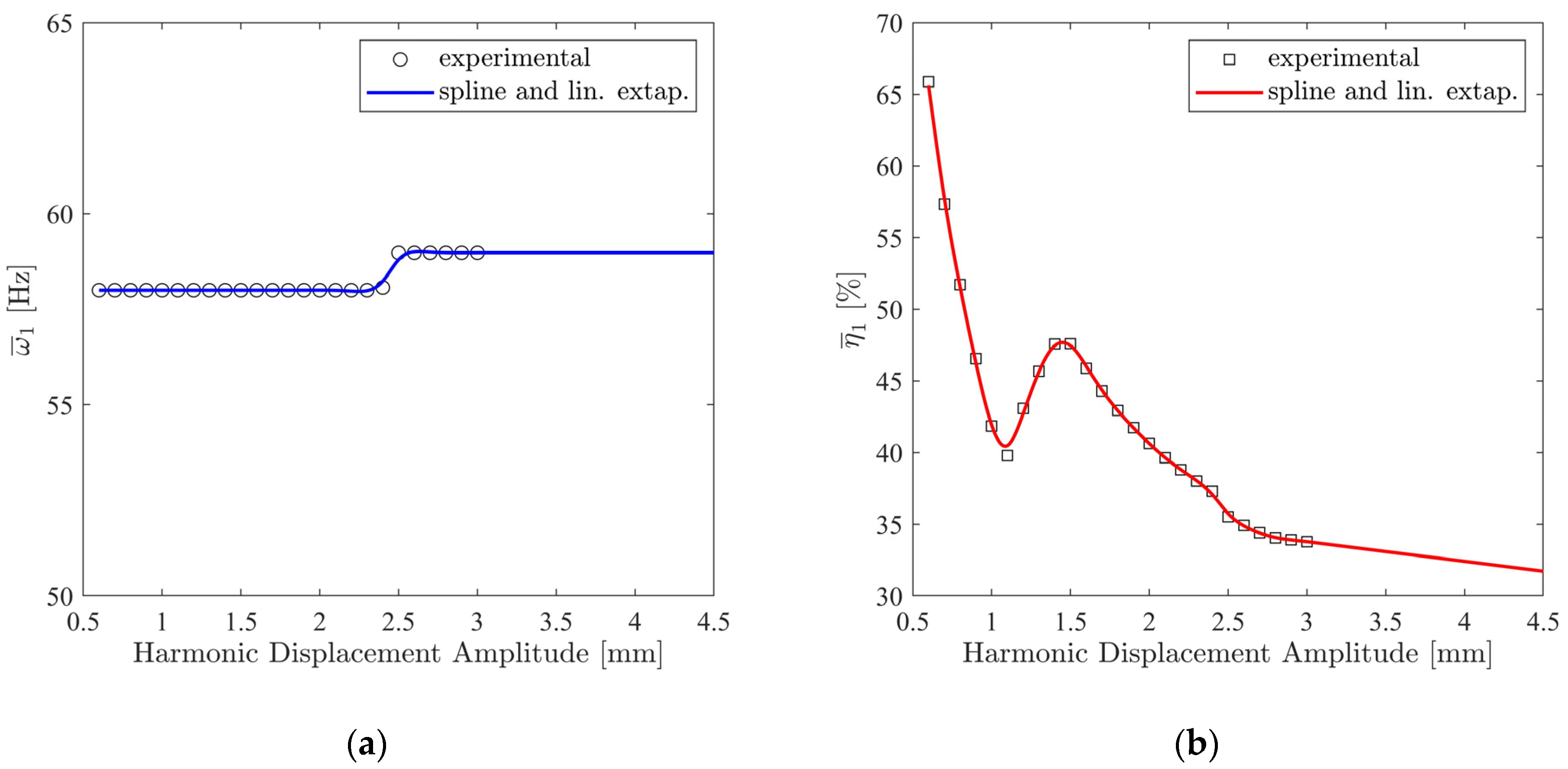
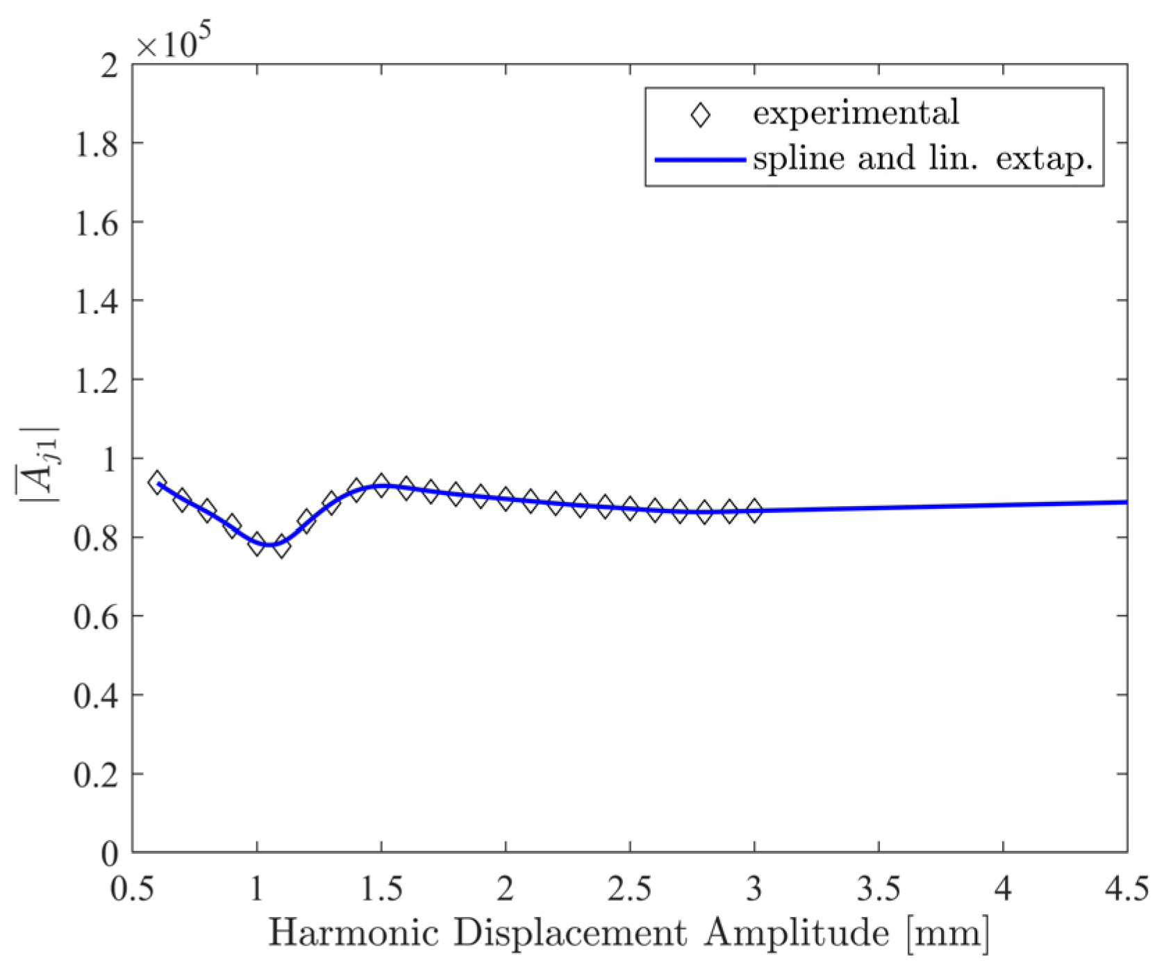
13]. The identified modal parameters are illustrated in
Figure 18 and
Figure 19.
The most important conclusion that can be drawn from
Figure 18 is that the enhanced compressor prototype exhibits extremely high and nonlinear damping that goes up to 65%. However, the system exhibits very weak stiffness nonlinearity.
In order to validate the accuracy of the identified nonlinear modal parameters, constant-current FRFs were synthesized by iteratively solving Equation (1) with the Newton–Raphson method and the arc-length continuation algorithm. Then, the synthesized FRFs were compared with the directly measured FRFs in
Figure 20.
Figure 20 shows that the match between the synthesized and measured frequency response curves is very satisfactory up to and including the 1.75 A level. At the current level of 2 A and above, the match is not good, especially near the resonance peaks. A careful investigation of
Figure 17 and
Figure 18 makes the reason behind this discrepancy clear. In
Figure 17, the constant-response FRFs are plotted only up to the 3 mm response level because cutting the HFS at higher levels captures only a small portion of the FRFs, which does not include half-power points and impedes the modal analysis. Accordingly, the nonlinear modal parameters could only be identified up to the 3 mm level, as illustrated in
Figure 18 and
Figure 19. However,
Figure 20 indicates that the constant-current frequency response curves at and above the 2 A current level go above 3 mm near resonance, and therefore their synthesis requires extrapolation, as shown in
Figure 18 and
Figure 19. In this first attempt, the synthesis was based on the linear extrapolation of the nonlinear modal parameters, which did not give satisfactory results.
In order to increase the accuracy of the nonlinear modal model, another approach is proposed herein. In this approach, the first step is the linear extrapolation of the HFS itself, as shown in
Figure 21, instead of the direct extrapolation of the identified nonlinear modal parameters. The extrapolated part is shown in the red color in
Figure 21. This makes it possible to extract quasi-linear FRFs at higher response levels up to 4.5 mm, including half-power points, which are the highest response levels reached in
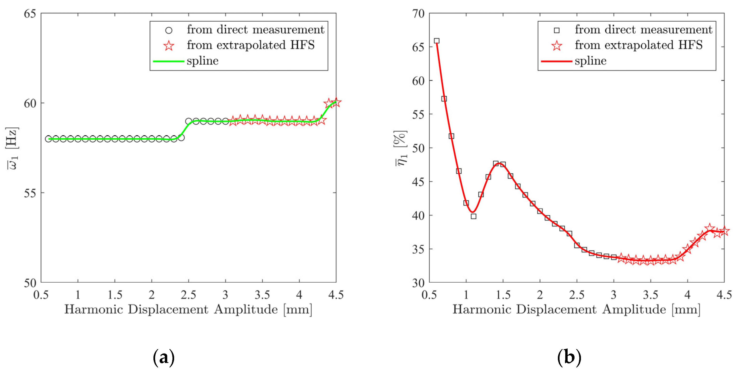
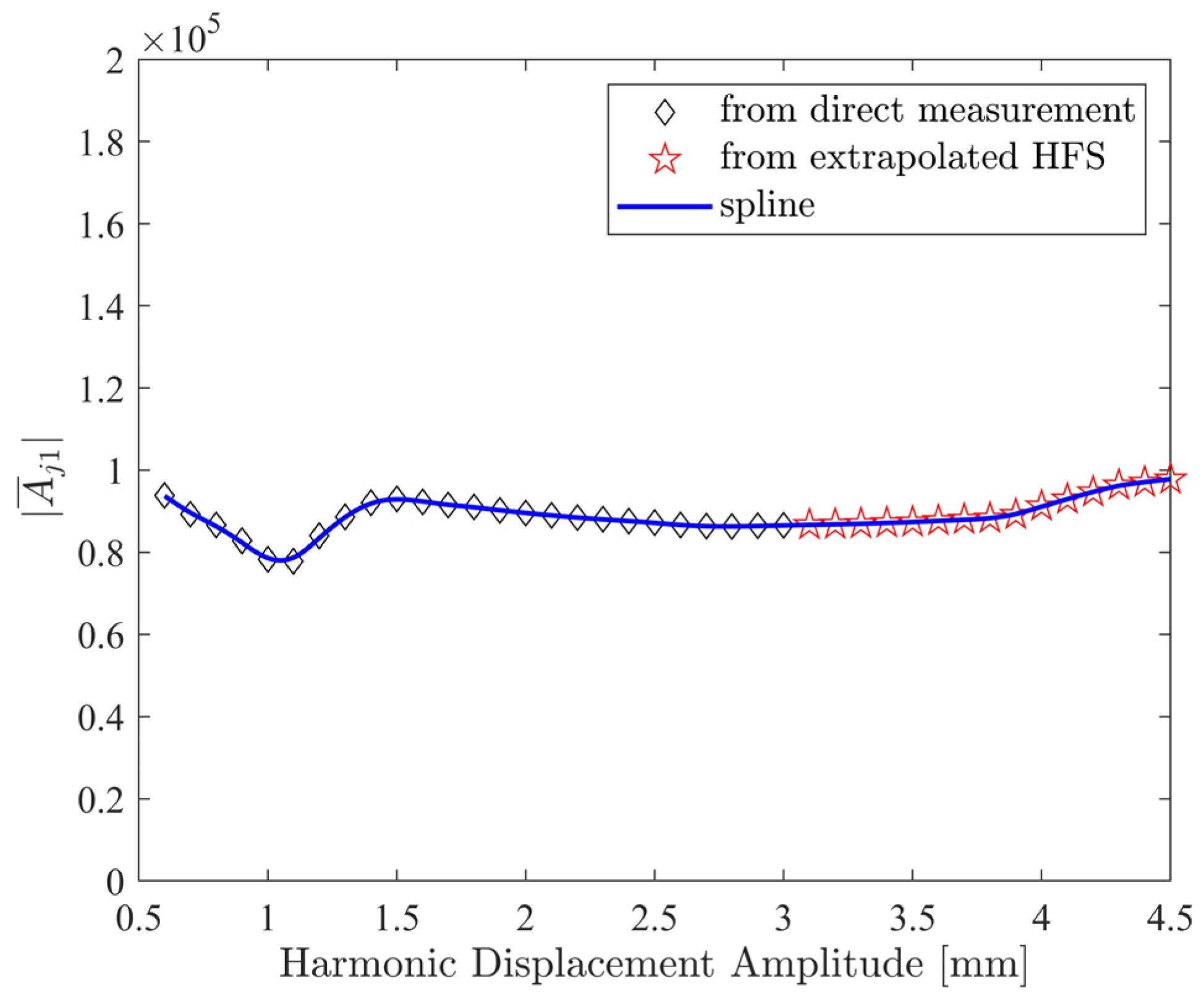
Figure 20. Variations in the nonlinear modal parameters identified from the extrapolated HFS are shown in
Figure 22 and
Figure 23. In these figures, modal parameters identified from the extrapolated HFS and corresponding to response amplitude levels above 3 mm are indicated with the red star markers. A comparison of
Figure 22 with
Figure 18 indicates that the modal damping ratios predicted by the proposed approach for amplitude levels above 3 mm considerably deviate from those predicted by the direct linear extrapolation. As seen in
Figure 18, the direct linear extrapolation predicted a damping ratio monotonically decreasing from 34% to 32%. However, according to
Figure 22, the damping ratio remains constant around 34% up to the 4 mm amplitude level, and it slightly increases up to 37% around the 4.5 mm amplitude level.
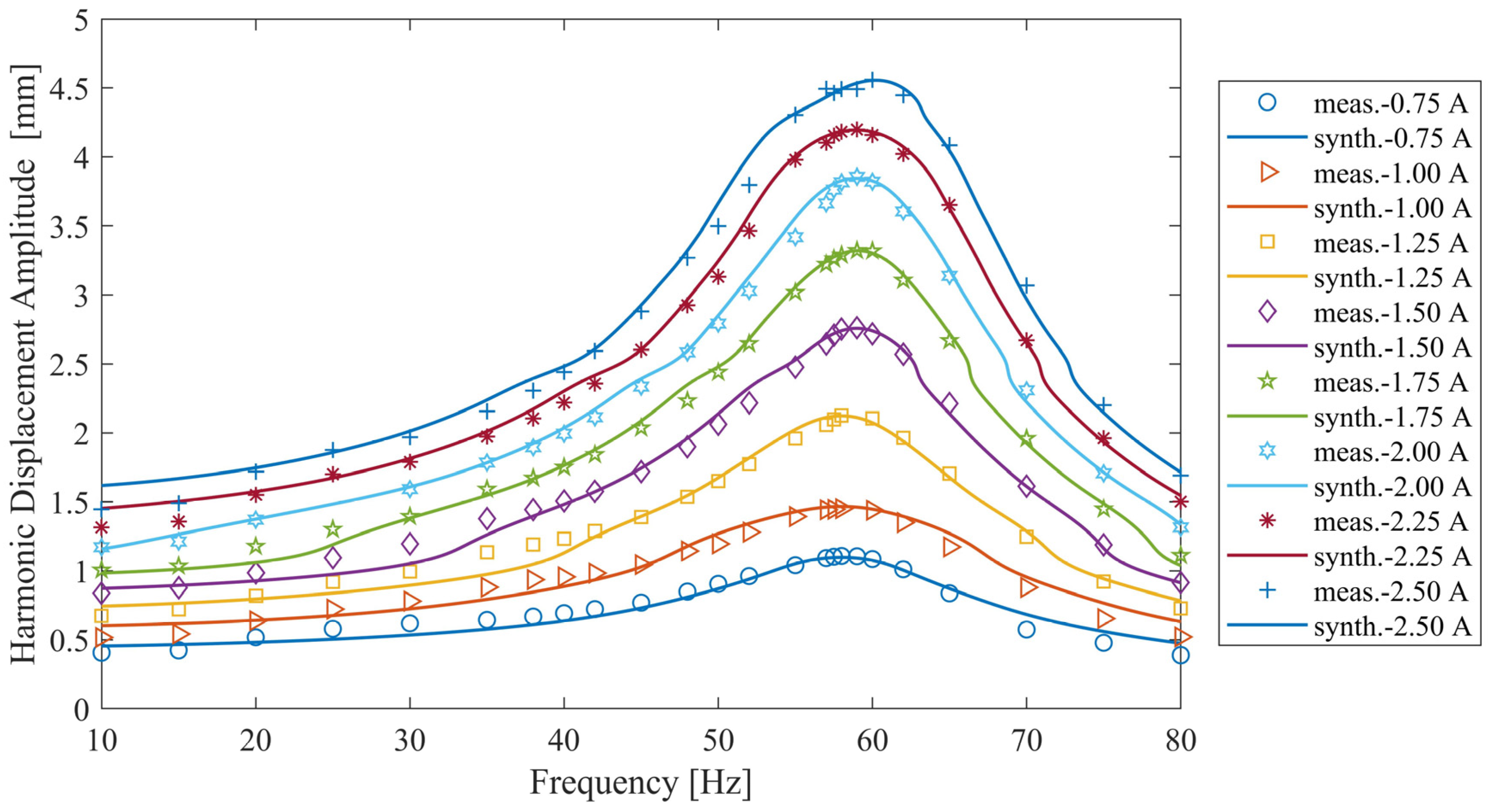
Finally, the accuracy of the extrapolated-HFS approach was validated by comparing the synthesized FRFs with the directly measured FRFs in
Figure 24. The synthesized FRFs in the figure were obtained by inserting the identified nonlinear modal parameters shown in
Figure 22 and
Figure 23 into Equation (1) and iteratively solving it with the Newton–Raphson scheme and arc-length continuation algorithm at different constant-amplitude current levels. Surprisingly, an excellent match was achieved between the synthesized and measured FRFs at all the current levels. Comparing
Figure 20 and
Figure 24, it can be concluded that the nonlinear modal parameters (
Figure 22 and
Figure 23) identified from the extrapolated-HFS approach predicted constant-current frequency response functions much more accurately than the nonlinear modal parameters (
Figure 18 and
Figure 19) estimated by the direct linear extrapolation at ampere levels of 2.0 A and above, where the response amplitude exceeded the 3 mm amplitude level. Consequently, the proposed extrapolation scheme can be regarded as a valuable contribution to the literature.


