1. Introduction
This study was inspired by the work of Javorski [
1], who first characterized the dynamic behavior of a ceiling-mounted basketball goal using an impact hammer and a fixed-location accelerometer, and then compared that empirical analysis to a theoretical finite element analysis. Empirical vibration measurements were taken at fourteen nodes, ten of which were on the frame supporting the basketball rim and backboard. Only four nodes were measured on the backboard, at the corners of the backboard, and none on the rim itself. Overall, 36 frequency response functions were measured, and this study concentrated mostly on structural vibrations between 2 and 10 Hz. Thus, this important study was focused more on the structural support of the backboard and rim rather than the elastic vibrations of the backboard and rim themselves. Our goal was to follow Javorski’s lead and see how many empirical modal frequency and mode shapes of the basketball rim and backboard which we could match with our theoretical finite element analysis.
ANSYS was chosen as our finite element package of choice for two major reasons. The first reason was that bundled education on this package was available online through Cornell University [
2]. MAE-141 taught the conceptual foundations of finite element analysis, MAE-142 taught ANSYS mechanical concepts and implementation, MAE 143 taught elasticity applications, and MAE-144 taught beam and shell applications. Most importantly, the final module in this bundle, MAE-145, taught vibration applications, which was very helpful. Each of these five modules contained lecture materials, quizzes, and a comprehensive hands-on student project. In this course, emphasis was placed on using the ANSYS Tree Outline to organize one’s efforts, which we fully adopted along with all methodology taught. The second reason was the free ANSYS 2024R1 student edition [
3].
Another important source to get us pointed in the right direction was the basketball rim and backboard modeled in ANSYS by Tickoo [
4]. Tickoo’s modeling did not use the precise dimensions as specified by the NCAA [
5] or Gared [
6]. However, he did get us started using DesignModeler within ANSYS for creating our geometry. We followed his lead of first creating the toroidal rim. Secondly, we followed his process of creating a new offset plane, followed by sketching a rectangle (saw icon), then extruding that rectangle from the offset plane to the toroidal rim to create the top of the mount. Finally, we followed his process of creating yet another new offset plane, followed by sketching yet another rectangle (saw icon), then extruding that rectangle from that second new plane to create the back of the mount. The use of ANSYS to study plate vibrations by Nkounhawa et al. [
7] and Guguloth et al. [
8] were also very helpful.
2. Materials and Methods
We first launched ANSYS Workbench 2024R1, then double clicked on MODAL under Analysis Systems in Workbench. This caused the MODAL cell to be displayed in the project schematic window. We then right clicked on Geometry within MODAL and selected DesignModeler Geometry from the menu. We used English units because all of the dimensions of the basketball rim, mount, and backboard are specified in inches in the United States.
Figure 1,
Figure 2 and
Figure 3 define how we established the geometry for the rim, its mount, the backboard, and the aluminum frame.
As shown in
Figure 1, the 18-inch internal-diameter toroidal rim was created in step 1 to NCAA specifications [
5] and Gared specifications [
6]. For this, we used the toroid listed in the create-primitives section. Step 2 was used to create an offset-YZ plane, followed by sketching a rectangle (saw icon) in step 3, then extruding that rectangle from the offset-YZ plane (plane of the backboard) to the toroidal rim to create the top of the mount, step 4, also to NCAA specifications [
5] and Gared specifications [
6].
Steps 2–4 began a repetitive process shown in
Figure 1,
Figure 2 and
Figure 3 of sketching a geometry (typically a rectangle) and extruding that geometry, and creating a new plane when needed. For example, the rectangle used to create the back of the mount was defined in step 5, then that rectangle was extruded to create the back of the mount in step 6, to Gared’ specifications [
6]. Finally, in
Figure 1, a rectangle was sketched in step 7 and extruded in step 8 to create the left inner mount flange, also to Gared specifications [
6].
In
Figure 2, a rectangle was sketched in step 9 and extruded in step 10 to create the right inner mount flange. In step 11, an offset-ZX plane was created, then a sketch of a triangular cutout was made in step 12. In step 13, this triangular cutout was extruded as a material removal, to finalize the five-sided inner flanges. In step 14, a horizontal offset-XY plane was created, then a pair of concentric semicircles were connected at their ends in sketch step 15 before being extruded in step 16 to create the wing brace which attached to the rim. This was followed by sketching a rectangle in step 17 and extruding it in step 18 to form the right outer flange. Then a matching rectangle was created in step 19 and extruded in step 20 to form the left outer flange. Steps 9–20 were performed to match Gared specifications [
6]. The wing brace, as well as both the inner and outer flanges, were modeled as 3/16 inch [4.7625 mm] thick steel plate.
In
Figure 3, a circle was sketched in step 21 and then extruded in step 22 to form the pivot rod of the break-away release mechanism, matching Gared specifications [
6]. This completed the geometric definition of the rim and its mount. Next came a rectangular sketch of the backboard in step 23, and the extrusion of that backboard and its frame in step 24. Step 25 utilized the slice function to separate the rim and its mount from the backboard so that the rim and mount could be declared to be made of steel. Specifically, we used slice—select face—generate. The rim-mound subassembly was then reunited with the backboard by the use of form-new-part to create an assembly of the individual component parts, as shown in
Figure 3.
When the backboard was extruded, its thickness was declared to be the thickness of the tempered glass and the thickness of the aluminum frame behind the tempered glass. In step 26, an offset-YZ plane was created so that the metal frame could be sliced from the obverse side of the backboard in step 27. This allowed the backboard to be declared to be made of half-inch [12.7 mm]-thick tempered glass, and the metal frame to be made of aluminum. At this point, the metal frame was a rectangle the same width and height as the backboard. To make the aluminum frame into a border frame, a second slightly smaller rectangle was created in step 28 and extruded as a slice in step 29, to remove unwanted aluminum. This concluded the geometry definition with one part comprising four bodies, the steel rim and mount, the glass backboard, the aluminum border frame, and the material removed from the solid piece of aluminum to make the aluminum border frame. The material removed to create the aluminum border frame was then suppressed to take it out of the analysis; hence the “x” next to it at the bottom left of
Figure 3.
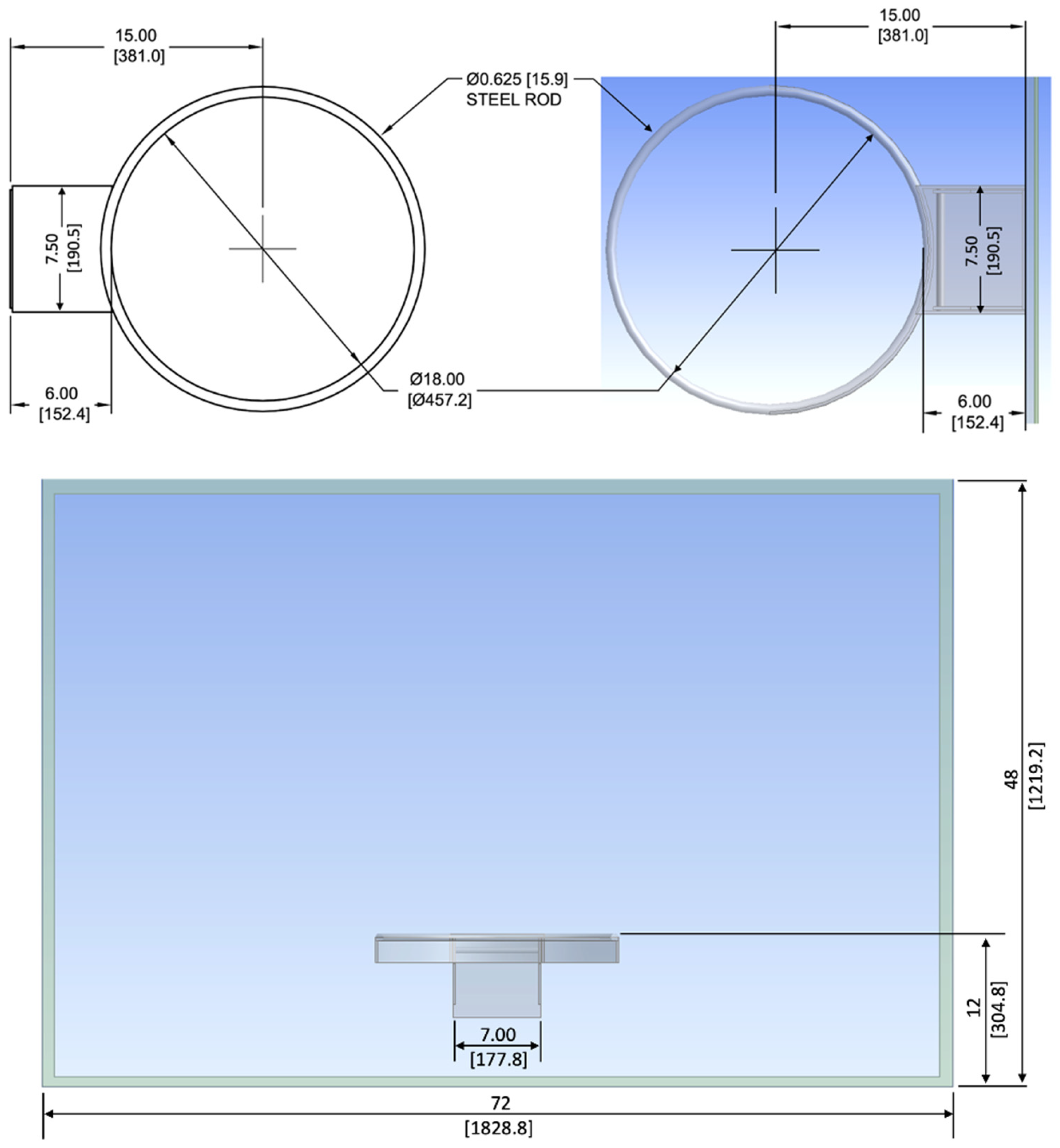
Figure 4 gave the major dimensions of the basketball rim and backboard which were used in the steps listed in
Figure 1,
Figure 2 and
Figure 3. These dimensions, in English inches followed by the respective millimeter equivalents in brackets, came from NCAA specifications [
5] and Gared specifications [
6], except for the 7.5 inch [190.5 mm] dimension which was measured with calipers. The upper-left top-view in
Figure 4 came from Gared [
6]. The upper-right top-view and the lower front-view came from our finite element model.
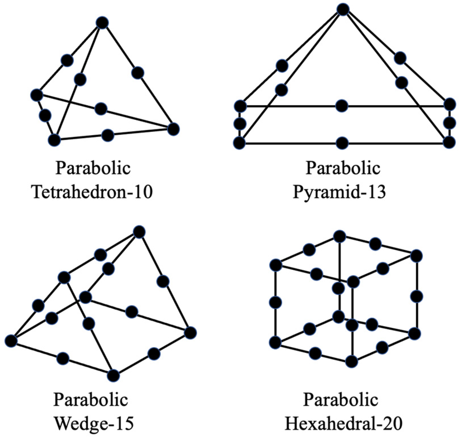
The next step was to exit Geometry and enter Model within the MODAL cell. Once in Model, the three-dimensional elements shown in
Figure 5 were used to create both meshes seen in
Figure 6 and
Figure 7.
Figure 5 was inspired by the sports-related application of finite elements in [
9,
10,
11,
12,
13], as these references listed what types of finite elements were used.
The 4618 three-dimensional elements in
Table 1, generated by ANSYS mesh parameters set to program default, were all parabolic and comprised a 4218 tetrahedron-10, 196 pyramid-13, 8 wedge-15, and 196 hexahedron-20 elements. As shown in
Figure 5, the parabolic tetrahedron element had 4 corner-nodes and 6 mid-nodes, for a total of 10 nodes. The parabolic pyramid element had 5 corner-nodes and 8 mid-nodes, for a total of 13 nodes. The parabolic wedge element had 6 corner-nodes and 9 mid-nodes, for a total of 15 nodes. Finally, the parabolic hexahedral element had 8 corner-nodes and 12 mid-nodes for a total of 20 nodes.
Table 1 used a total of 11,200 unique nodes comprising 2218 unique corner-nodes and 8982 unique mid-nodes. The sum of the nodes, corner-nodes, and mid-nodes in the rim and mount, backboard, and frame exceeds the number of unique nodes due to node sharing where these parts interface.
Table 1, above, shows that the rim and mount were originally modeled, using default parameters within ANSYS, with 1979 tetrahedron-10 elements. The backboard was originally modeled with 2239 tetrahedron-10 and 196 pyramid-13 elements, and the aluminum frame was originally modeled with 8 wedge-15 and 196 hexahedral-20 elements.
Table 2, below, shows the changes made via a refined-mesh, where the number of elements was increased by 82%, from 4618 to 8410.
Table 2 shows that the rim and mount were then modeled with 2110 (previously 1979) tetrahedron-10 elements. The backboard was then modeled with 6056 (previously 2239) tetrahedron-10 and 120 (previously 196) pyramid-13 elements, and the aluminum frame was then modeled with 4 (previously 8) wedge-15 and 120 (previously 196) hexahedral-20 elements. This mesh refinement was inspired by [
9]. Both
Table 1 and
Table 2 were dominated by tetrahedron elements, which was the primary element used in [
9].
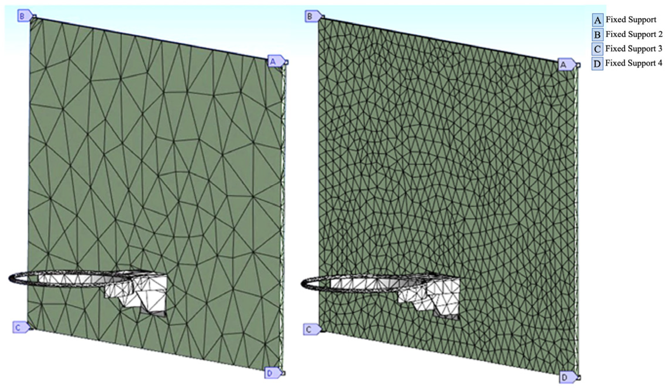
After the original-mesh and the refined-mesh were separately created, four fixed support conditions were individually applied, one to each of the four outer corner vertices of the aluminum frame behind the backboard, as shown in
Figure 6, above. The zoom showing the location of fixed support “D” at an outer corner was equally applicable of fixed supports “A”, “B”, and “C”. The choice of the four fixed support conditions was based on our previously published mode shapes [
14] and the support conditions used by Javorski [
1]. With the help of the “Details of Mesh” feature of ANSYS,
Figure 6 was summarized in
Table 1 for the original-mesh and in
Table 2 for the refined-mesh. Because elements are not shared between individual parts, the sum of the elements used to model the rim and mount (1979), backboard (2435), and aluminum frame (204) equaled the total (4618) number of elements in
Table 1 and the left image in
Figure 7. Similarly, the sum of the elements used to model the rim and mount (2110), backboard (6176) and aluminum frame (124) equaled the total (8410) number of elements in
Table 2 and the right image in
Figure 6.
4. Discussion of Results
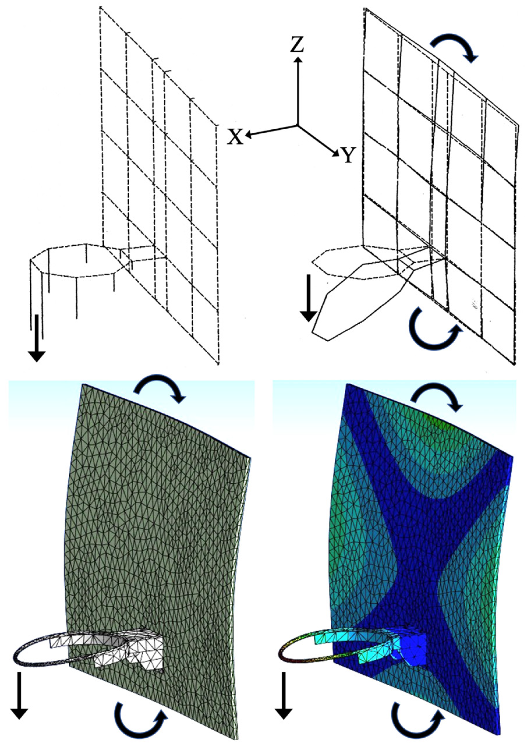
Figure 8,
Figure 9,
Figure 10,
Figure 11 and
Figure 12 compared our previously published empirically measured frequencies [
14] with the theoretical output of the refined-mesh ANSYS finite element analysis, as tabulated in
Table 3, below.
Table 3 also compared our previously published empirically measured frequencies [
14] with the theoretical output of both the original-mesh and the refined-mesh ANSYS finite element analyses.
Figure 8 exhibited an in-phase rocking motion of the rim and backboard, which was indicative of a lower-frequency mode.
Figure 11 was interesting because both the empirical modal analysis and the theoretical finite element analysis showed that the steel rim was flexing. As the mount and inner portion of the rim flexed upward, the outer portion of the rim flexed downward, and vice versa. The characteristic oscillating central bulge in the backboard plate prominent in
Figure 11 can also be found in [
15,
16,
17,
18].
Figure 12 was interesting because both the empirical modal analysis and the theoretical finite element analysis showed that the steel rim was twisting in a torsional mode about the X-axis. As stated in [
14], the rim was originally modeled as an octagon for the purpose of empirical modal analysis. This offset the fixed-location accelerometer used in the empirical modal analysis from being at the outer end of the rim. Thus, our accelerometer was able to detect the vertical Z motion of this torsion mode.
Using the =PEARSON statistical correlation function in Excel, a correlation between the empirical modal analysis and theoretical ANSYS finite element analysis was calculated at 97.187% for the 4618-element original-mesh, and 98.09% for the 8410-element refined-mesh. A value of 100% would have represented a perfect correlation, a value of 0% would have indicated no correlation, and a value of −100% would have indicated a perfect inverse correlation. The Excel regression function gave a value of F = 51.076 and the square root of F (test statistic) of 7.147 for the original-mesh, and F = 76.52 and the square root of F of 8.747 for the refined-mesh. Using the Student-t distribution for N = 5 sample pairs, with N − 2 = 3 degrees of freedom, showed that 7.147 and 8.747 both exceeded 5.841 [
19] which was needed for confidence of 99.5% in both of our correlations. A graphical comparison of the correlation of the theoretical finite element analysis and empirical modal frequencies of the 8410-element refined-mesh model is shown in
Figure 13, below.
Figure 8,
Figure 9,
Figure 10,
Figure 11 and
Figure 12 all showed that the basketball rim was oscillating perpendicular to the XY (horizontal) plane. As stated in [
14], the fixed-location accelerometer used in the empirical modal analysis was near the outer end of the rim and pointed in the vertical Z direction, so the accelerometer would be primarily sensitive to motion perpendicular to the horizontal XY plane. Thus, it is understandable that the theoretical finite element modes shown in
Figure 14, below, were missed by the empirical modal analysis because the theoretical motion of the rim in each mode in
Figure 14 was entirely within the XY plane.
The missed mode at 11 Hz comprised a piston-motion of the rim and mount in the ±X direction. The missed modes at 28 Hz and 44 Hz comprised the reciprocating rotational motion of the rim and mount about the Z-axis. The missed mode at 28 Hz had previously perplexed the authors’ empirical modal analysis [
14] as that was a common mode of vibrations in plates [
16,
17,
18]. But we now understand that the lack of vertical motion of the rim in
Figure 14 meant that any signal from the vertically oriented accelerometer could have easily been overlooked as noise. This showed us that first obtaining simulation results via finite element analysis could help the planning of subsequent modal analysis experiments.
5. Conclusions
Via an ANSYS Tree Outline, 29 steps were documented in detail for the use of the ANSYS MODAL analysis system to create a geometry, mesh, and boundary conditions for a basketball rim, mount, backboard, and border frame.
The purpose of this theoretical finite element analysis was the identification of theoretical modes and frequencies of vibration of one basketball hoop and backboard design. Five empirical modes of vibration compared favorably with this theoretical finite element analysis. These five modes were addressed from a finite element model validation standpoint by statistical correlations with empirical modal analysis data and from a verification standpoint by employing a refined-mesh. The original finite element mesh, generated by default parameters in ANSYS, had a 99.5% confidence in a 97.187% cross-correlation. The refined-mesh, which increased the number of finite elements by 82%, had a 99.5% confidence in a slightly higher 98.09% cross-correlation. The high correlations between the theoretical finite element modeling and the empirical modal analysis were considered a validation of our work. The fact that the refined-mesh did not alter the mode shapes and only made minor changes to the mode frequencies was considered a verification of our finite element model.
There are many possible designs of rims, backboards, and frames which meet NCAA standards, so this study was not comprehensive across the sport of basketball. However, our efforts of finite element analysis did reasonably match empirically measured mode shapes and frequencies of our previously published data. Also, we showed the potential need for a triaxial accelerometer for any future empirical modal analysis efforts involving basketball rims and backboards.


