Article

Vertical Transient Response Analysis of a Cracked Jeffcott Rotor Based on Improved Empirical Mode Decomposition

Department of Mechanical, Industrial and Aerospace Engineering, Concordia University, Montréal, QC H3G 1M8, Canada
*
Author to whom correspondence should be addressed.
Vibration 2022, 5(3), 408-428; https://doi.org/10.3390/vibration5030023
Submission received: 20 April 2022 / Revised: 30 June 2022 / Accepted: 30 June 2022 / Published: 2 July 2022

Abstract

:
The crack-induced changes in the vertical transient response of a rotating shaft–disc system, Jeffcott rotor, are investigated for transverse crack detection. The crack is considered as a breathing crack. A novel breathing function is proposed, in which the partially open–closed crack breathing behavior is interpolated between the fully open and closed crack behaviors. The breathing crack excites superharmonic response components of the transient as well as the subharmonic components. A Hilbert–Huang transform based on an improved empirical mode decomposition algorithm is subsequently formulated to evaluate the time–frequency representation of the vertical transient response of the rotor to detect the crack. The results show that the proposed breathing function can effectively reduce the computational effort without sacrificing the accuracy of the crack breathing behavior in the presence of small cracks. It is shown that time–frequency representations based on an improved empirical mode decomposition algorithm can lead to the detection of smaller cracks compared with those based on the empirical mode decomposition algorithm.

1. Introduction

The propagation of a fatigue crack in rotary machines can adversely affect the operational efficiency of the system and could lead to unscheduled failures. In the past few decades, a variety of vibration-based methods have been proposed for the detection of a crack at the onset of its propagation in a rotating shaft. These are mainly based on identifications of relative changes in steady-state and transient vibration responses of the system to detect crack properties such as depth and location. The rotor transient response analysis has been a tool of great interest in crack detection and diagnosis. The start-up and run-down transient lateral responses of a cracked rotor while passing a critical speed can provide valuable information for crack detection [1,2,3,4].
The equations of the lateral motion of shaft–disc systems have been reported in many analytical (e.g., [5,6,7,8,9,10]) and numerical (e.g., [11,12,13,14,15,16,17,18]) studies. These models have been mostly derived using the Euler–Bernoulli (e.g., [7,19]) and Timoshenko beam theories (e.g., [10,16,20]). The Jeffcott rotor model, as a simplified lumped analytical model, has also been used in obtaining the steady-state (e.g., [5,6,21]) as well as transient lateral responses (e.g., [4,22,23]) of shaft–disc systems. This model considers a single rigid disc on the midspan of a massless flexible shaft to obtain vibrational properties in the vertical and horizontal directions.
The local stiffness of the shaft is affected by the presence of the crack and consequently the dynamic behavior and vibrational properties of the shaft–disc system. Modeling the crack has been an important challenge in many studies, which involves two distinct steps: (i) calculation of the shaft cross-section stiffness reduction due to crack and (ii) determination of relation function between shaft stiffness reduction and shaft rotation. The changes in shaft cross-section geometry in the vicinity of the crack, and thereby changes in the local stiffness of the shaft, strongly depend on the crack depth, which are generally obtained using the concepts of strain energy release rate and stress intensity factor [24,25] or changes in area moment of inertia about the transverse coordinates of the cracked shaft [16,26].
In the case of a crack with negligible thickness in axial direction, the crack geometry also changes as the shaft static deflection dominates the lateral vibration [14]. A crack is modeled as an open crack when the variations in the stiffness due to the shaft rotation are considered negligible [6,27]. Alternatively, in a breathing crack model, the effect of the shaft rotation on the crack geometry is incorporated to accurately describe the localized stiffness reduction due to the crack at each shaft angle. [28,29,30].
The majority of the breathing crack models employ explicit functions such as step or cosine functions to calculate breathing behavior of the partially open–closed crack by interpolating between fully open and closed crack behaviors (e.g., [17,31,32]). Some studies have also reported to evaluate breathing behavior of the crack corresponding to different shaft angles using linear fracture mechanics [10,21,25] and changes in area moment of inertia about the transverse coordinates of the cracked shaft cross-section area [14]. These studies could describe the breathing crack behavior more accurately for a wide range of crack depths. These, however, impose greater computational efforts compared with the studies using interpolations.
The crack-induced changes in different vibrational properties such as critical speeds, emergence of subcritical resonant peaks, whirl orbit evolution at subcritical speeds, torsional-lateral vibration coupling, and equivalent fictitious loads have been utilized for detection of cracks in rotating shaft–disc systems (e.g., [14,17,21,26,27,32,33,34,35]). The changes in transient lateral responses of the shaft–disc system have also been investigated in many studies for crack detection. Plaut et al. [19] have considered the effects of crack parameters, depth and location, and shaft acceleration and deceleration rate on the maximum transient response with passing through the first critical speed of the system as a reliable crack indicator. Sawicki et al. [3] have suggested that the “saw-cut” pattern in the vibration phase response as the rotor accelerates can be considered as a crack indicator. Darpe et al. [4] have considered shaft center orbit evolution and relatively stronger superharmonic components in the horizontal direction than in the vertical direction passing through subcritical resonances as reliable crack indicators. Sampaio et al. [36] have applied the Approximated Entropy (ApEn) algorithm to detect breathing cracks during run-up or run-down transient responses of a rotating shaft. The ApEn algorithm is an efficient method in the identification of irregularities and unpredictable fluctuations in time data series. Nicoletti et al. [37] merged the ApEn algorithm with the combination resonances approach to detect cracks while the rotor operates at constant speeds.
The emergence of low-amplitude subcritical resonant peaks in rotor transient response has been considered as a reliable crack indicator. The subcritical resonant peaks are affected by several parameters such as start-up/run-down rotational acceleration/deceleration rates and unbalance phase as reported in [4,38]. The subcritical resonant peaks, however, are usually hard to detect in time response, especially in the presence of small cracks. Analyzing the transient response using signal processing techniques may reveal useful information to find subcritical resonant peaks, which are not detectable in the time domain.
Darpe et al. [4] applied the Fourier transform technique to extract the frequency content of transient response near subcritical speeds. Fourier transform is a suitable signal processing method for analyzing signals, when their frequency contents do not change in time (stationary signals). The transient responses of rotor–disc systems, however, exhibit notable changes in the frequency content in time (nonstationary signals), which could be extracted using advanced signal processing techniques such as the Wigner–Ville distribution transform, wavelet transform (WT) and Empirical Mode Decomposition (EMD).
The performance of the Wigner–Ville distribution in crack identification using the transient response has been evaluated by Zou et al. [22]. The study concluded that the Wigner–Ville distribution is highly sensitive to small shaft stiffness changes due to small cracks. Sekhar [39] suggested that the continuous wavelet transform (CWT) could serve as a powerful tool for crack detection in a Jeffcott rotor coasting down through its critical speed. The energy of the CWT has been shown to be sensitive to the crack depth and can be applied as an efficient crack indicator. Sekhar [40] also showed that the CWT is a powerful tool in crack detection, particularly in high start-up accelerations.
The wavelet transform yields high-resolution frequency analysis for the entire time signal, although the time and frequency resolutions are highly affected by the chosen mother wavelet [41]. Alternate methods, such as empirical mode decomposition (EMD), have been applied to obtain high-frequency resolution analysis without using preselected kernels. The EMD technique decomposes signal into a set of orthogonal components representing local characteristics of the time signal, which consequently yields local high-resolution frequency analysis. The Hilbert–Huang transform is a EMD-based transformation for finding the instantaneous frequency components of the signals [42]. Guo and Peng [43] and Ramesh et al. [20] have effectively applied the Hilbert–Huang transform for crack detection using transient responses. Guo and Peng [43] established the effectiveness of the Hilbert–Huang transform for detecting propagating transverse cracks, while Ramesh et al. [20] showed that the Hilbert–Huang transform outperforms the limitations of the CWT. Chandra and Sekhar [44] employed the EMD for the detection of shaft misalignment, cracks, and rotor stator rubbing faults in rotor bearing systems. From comparisons of the results of the time–frequency representations obtained from EMD with those obtained from CWT, the study concluded that the EMD method can lead to the detection of relatively smaller cracks with less computation time. Teyi et al. [45] have summarized all the signal processing techniques which have been applied in different crack detection methods in the past decade.
While time–frequency representations of the signals obtained from EMD methods exhibit a relatively higher local resolution frequency analysis, few studies have established their limitations [46,47]. A number of alternate approaches have been proposed to address these limitations of EMD, which include end effects (e.g., [48,49,50]), extremum interpolation (e.g., [51,52]), and mode mixing [53]. These studies have proposed extension methods, alternate interpolation approaches, and noise-assisted data analysis methods. Lei et al. [41] have presented a comprehensive review of improved EMD algorithms and their applications in rotating machine fault diagnosis.
In the present study, start-up transient responses of a shaft–disc system with different crack depths are considered. The shaft–disc system is analytically modeled as a Jeffcott rotor with a transverse fatigue crack to obtain the transient lateral response of the system as it passes through its critical speeds. The excitations of superharmonic components of the transient response and the emergence of subcritical peaks are considered for crack detection. The crack is modeled as a breathing crack using the model proposed by Darpe et al. [4], and an alternate explicit breathing function is also proposed to reduce its computational costs. The performances of the proposed crack detection methodology to find small size cracks based on EMD and an improved EMD method are compared.

2. Jeffcott Rotor and Crack Modeling

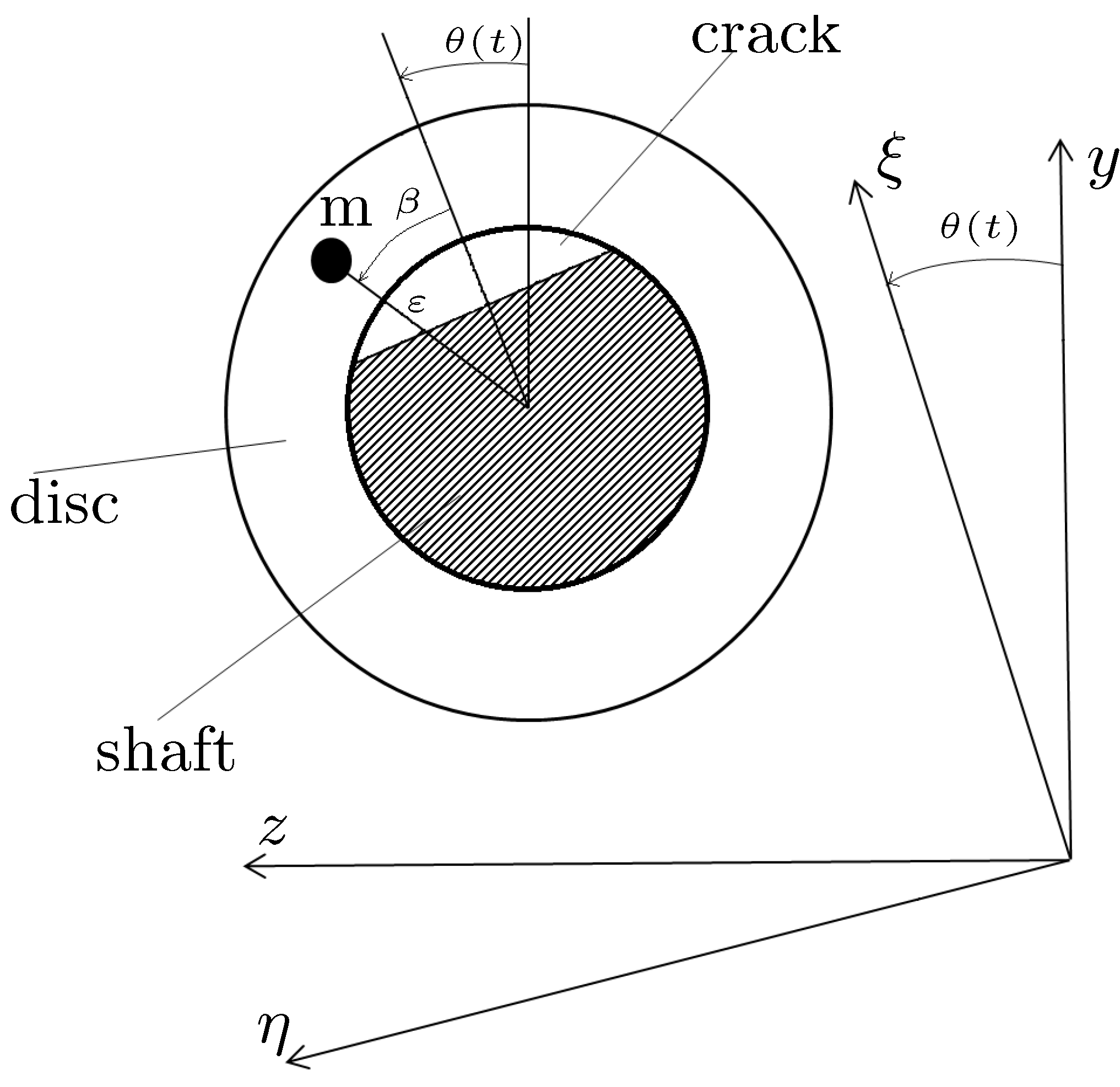
The Jeffcott rotor model considers a massless flexible shaft with a single rigid disc mounted on rigid-short bearing supports. The disc is located on the midspan of the shaft as shown in Figure 1. The governing equations describing the motion in the lateral directions in the stationary and rotating coordinates have been well-presented in [3,21]. The equations of motion in the rotating coordinate system, which rotate with the same velocity of the shaft, can be described as [3]:
M 0 0 M ξ ¨ η ¨ + C 2 M Ω 2 M Ω C ξ ˙ η ˙ + K ξ ξ M Ω 2 K ξ η Ω C M α r K η ξ + Ω C + M α r K η η M Ω 2 ξ η = M g c o s ( θ ) s i n ( θ ) + M ε Ω 2 c o s ( β ) + α r s i n ( β ) Ω 2 s i n ( β ) α r c o s ( β )
where M , C , ε , g , and β are the disc mass, external damping coefficient, unbalance eccentricity of the disc, acceleration due to gravity, and the angle between the unbalance and the ξ axis, respectively, as shown in Figure 2. In the above equation, θ ( t ) , Ω , and α r denote shaft rotational angle, rotational speed, and acceleration, respectively. The stiffness matrix of the shaft, K r , is defined in the rotating system as:
K r = K ξ ξ K ξ η K η ξ K η η

2.1. Crack Modeling

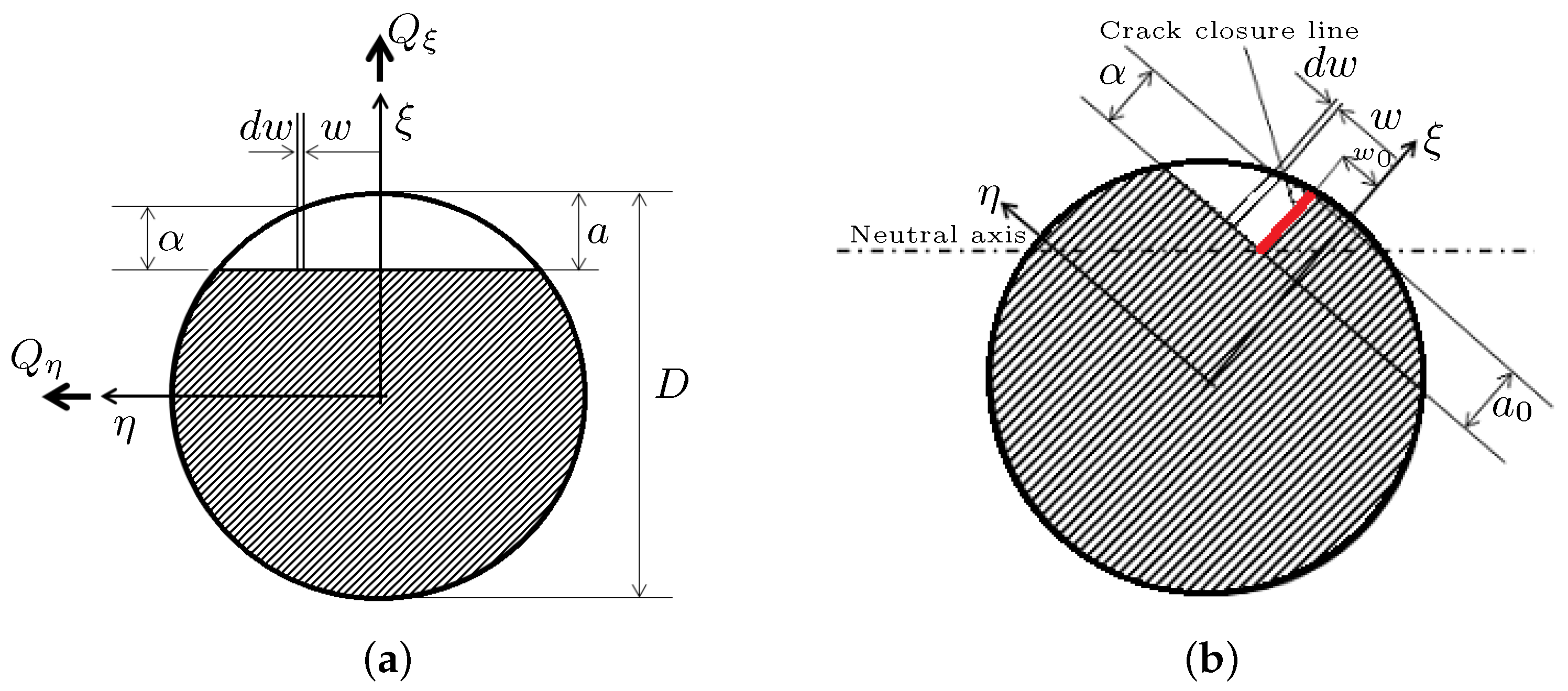
The presence of a transverse crack on a shaft causes a sudden change in the slope, which depends on crack depth and exhibits a reduction in the shaft local stiffness at the crack location. The crack-induced changes in local stiffness can be obtained using linear fracture mechanics theory [4,21,24,25]. June et al. [21] have obtained the shaft flexibility due to a fully open crack, as shown in Figure 3a. The study considered the strain energy density function, J ( α ) , in terms of stress intensity factor K I , as [21]:
J ( α ) = 1 E K I 2 K I = K Q ξ I + K Q η I
where K Q ξ I and K Q η I are the stress intensity factors corresponding to the opening mode of the crack due to forces Q ξ and Q η acting on the cracked shaft cross-section, respectively, as shown in Figure 3, which can be described as [21]:
K Q ξ I = Q ξ L 2 α / 8 I π α F α / α K Q η I = Q η L 2 w / 4 I π α F α / α
where L 2 and I are the length and second moment of area of the shaft, respectively, and the functions F and F are giving by:
F α / α = 2 α π α t a n π α 2 α 0.923 + 0.199 1 s i n π α / 2 α 4 c o s π α / 2 α F α / α = 2 α π α t a n π α 2 α 0.752 + 2.02 1 s i n π α / 2 α 3 c o s π α / 2 α
for the shaft with diameter, D, I = π D 4 64 and α = D 2 2 w 2 . Using Castgliano’s theorem, the additional deflections u i ( i = ξ , η ) due to the crack are obtained from [21]:
u i = U c Q i
where U c represents the additional strain energy due to the crack, which can be written in terms of the strain energy density function J ( α ) , as [21]:
U c = J ( α ) d α d w
The additional flexibilities are thus given by [21]:
g i j c = 2 Q i Q j a ( D a ) a ( D a ) 0 a D 2 + D 4 2 w 2 J ( α ) d α d w
Now, substituting Equations (4) and (5) into Equation (3), and the resultant into Equation (8), one can obtain:
g ξ ξ c = 128 L 2 2 α 2 E π D 8 α F 2 ( α / α ) d α d w g η ξ c = g ξ η c = 256 L 2 2 α w E π D 8 α F ( α / α ) F ( α / α ) d α d w g η η c = 512 L 2 2 w 2 E π D 8 α F 2 ( α / α ) d α d w
Thereby, adding the flexibilities of the uncracked shaft to the obtained crack-induced flexibilities, described in Equation (9), the compliance elements of the cracked shaft cross-area in ξ and η directions and the correspondence cross-coupled flexibilities can be described as:
g ξ ξ = L 2 3 48 E I + g ξ ξ c g η ξ = g ξ η = g η ξ c = g ξ η c g η η = L 2 3 48 E I + g η η c
Finally, the elements of the stiffness matrix K r , described in Equation (2), are oobtained as:
K r = G r 1 = g ξ ξ g ξ η g η ξ g η η 1
where,
k ξ ξ = g η η g ξ ξ g η η g ξ η 2 ; k η η = g ξ ξ g ξ ξ g η η g ξ η 2 ; k ξ η = k η ξ = g ξ η g ξ ξ g η η g ξ η 2
It should be noted that the compliance matrix G r is defined in the rotational coordinates. As mentioned before, Equation (11) provides the stiffness of a fully open cracked shaft. Furthermore, to obtain the localized stiffness of a shaft with a partially open–closed crack based on the Jun et al. [21] model, Darpe et al. [4] have proposed the concept of crack closure line (CCL), as shown in Figure 3b. This concept is based on the sign of the stress intensity factor at the crack edge. The stress intensity factor for each point at the crack edge on the left side of the CCL has a positive sign, which indicates that the crack is in tension and thus in open mode. The crack is considered to be closed on the right side of the CCL due to a negative stress intensity factor. For this case, Equation (8) is still applicable, however, the lower and upper limits in the double integral should be modified based on the position of the CCL, as [4]:
g i j c = 2 Q i Q j a ( D a ) w 0 0 a 0 J ( α ) d α d w
In this study, the Darpe et al. [4] breathing crack model has been applied to determine the transient response of a cracked Jeffcott rotor. While the breathing crack model proposed by Darpe et al. [4] can reasonably describe the breathing behavior of the crack at each shaft angle, it requires relatively high computational demand. An alternate explicit breathing function, obtained through trial and error, named “softly-clipped cosine function”, is proposed in order to reduce the computational efforts associated with the breathing model of Darpe et al. [4]. The proposed breathing function is formulated as:
f ( t ) = 1 2 5 9 c o s ( Ω t ) 1 18 c o s ( 3 Ω t π )
Figure 4 compares the proposed breathing function, Equation (14), with that of Darpe et al. [4]. It is also noted that the pattern of the Darpe et al. [4] breathing model changes as the normalized crack depth ( μ = a R , ratio of the crack depth a to the shaft radius R) changes. The pattern of the proposed breathing function is, however, independent of the normalized crack depth. The comparisons show that the proposed function provides good approximation of the Darpe et al. [4] breathing model, particularly for small cracks. Al-Shudeifat and Butcher [14] have also introduced two alternative breathing functions to describe the changes in the stiffness matrix elements of a rotating cracked shaft. They showed that the two new breathing functions are more accurate than the typical old breathing function applied in (e.g., [26,29]).

2.2. Method of Solution

Considering the stiffness matrix described in Equation (12), the governing equation of motion, Equation (1), is integrated using the fourth-order Runge–Kutta method to compute the transient start-up responses of the system with different crack depths for a determined acceleration rate. The integration of Equation (1) is carried out using a sufficiently small time step ( Δ t = 0.001 ) to ensure accurate solutions. In each time step, the stiffness values and shaft speed are considered to be constant. The shaft speed Ω and angular position θ are constantly updated using [3]:
Ω ( t ) = Ω 0 + α r t , Ω 0 = 0 θ ( t ) = θ 0 + Ω 0 t + α r t 2 2 , θ 0 = 0
The obtained lateral forces at each shaft angle, described in Equation (16), are also used to update the stiffness values for the subsequent time step using the crack breathing behavior models described in Section 2.1.
Q ξ Q η = k ξ ξ k ξ η k η ξ k η η ξ η
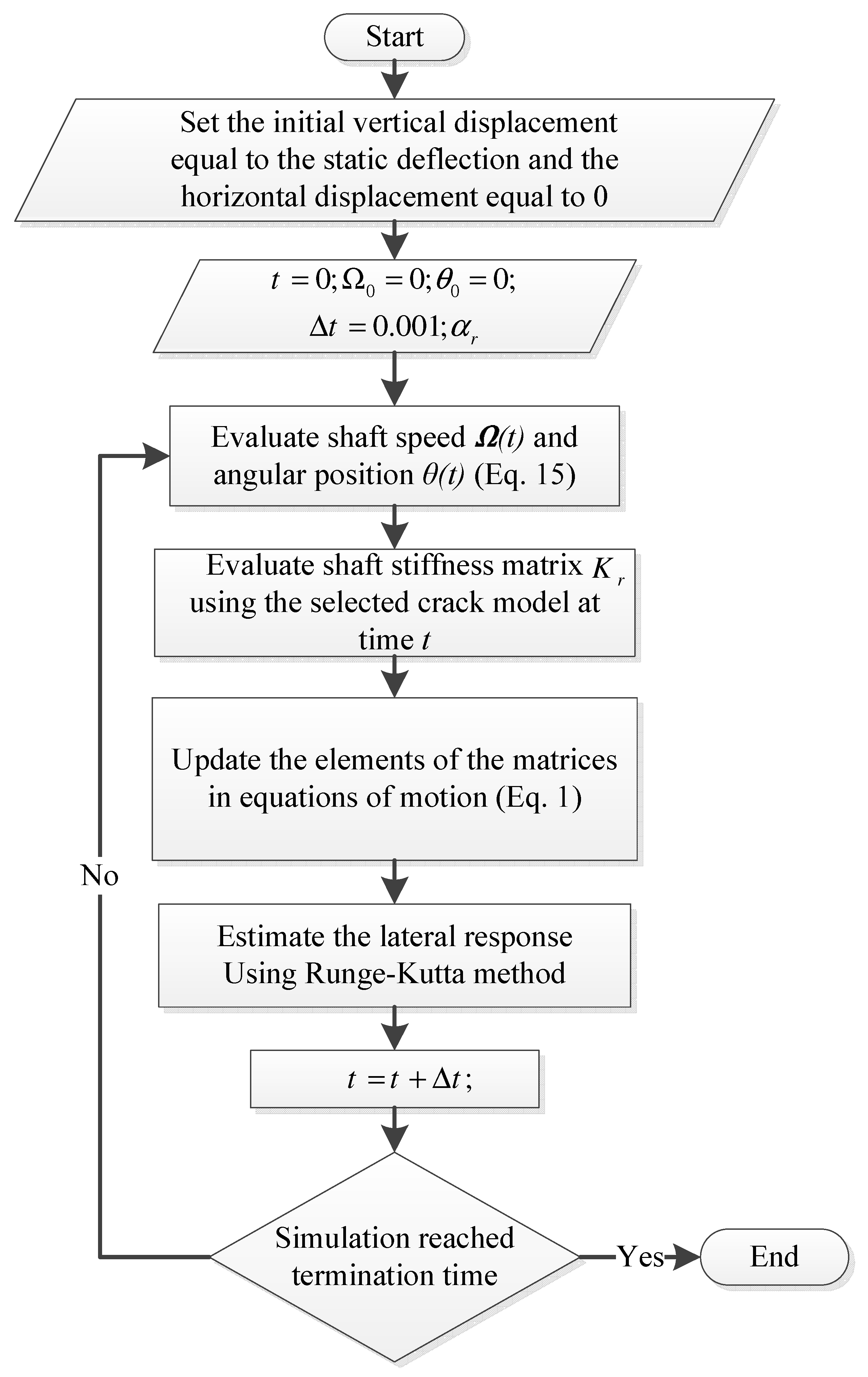
The initial displacement of the rotor in the vertical direction is assumed to be equal to the static deflection, while the initial horizontal displacement is set to 0. The rotor starts from the static position with a given constant acceleration rate α r . Figure 5 shows the flowchart of the proposed solution method for transient lateral response analysis of the shaft–disc system using the fourth-order Runge–Kutta method.
The superharmonic components of lateral response of the shaft–disc system passing through critical speeds are excited due to the presence of the breathing crack. The emergence of these superharmonic components is not clearly observable in the time response, particularly for the small cracks. However, utilizing time–frequency analysis based on different transform methods may reveal the crack-induced changes in the transient responses. A brief description of the time–frequency analysis used in crack detection in rotary systems is presented in the following section.

3. Time–Frequency Analysis

The Fourier transform is a well-known method to analyze stationary vibration signals. The Fourier transform method, however, is not well-suited for the determination of local changes in frequency contents of the cracked rotor transient responses, which generally exhibit nonstationary behavior. The Short-Time Fourier Transform (STFT) has been developed to analyze nonstationary signals. In STFT-based time–frequency representations, an identical window is used for analysis of the entire signal, which leads to a constant resolution for all frequencies. However, generally wide and narrow windows are required to obtain a good frequency resolution for low- and high-frequency components of a signal, respectively.
Alternatively, the wavelet transform can produce a multiscale frequency resolution to extract more effective time–frequency representations of nonstationary signals. In wavelet transform, signal features, which are well-correlated with the shape of the selected wavelet mother function have a higher chance to be observed in the time–frequency representations, while the features with lower correlations vanish. Therefore, the wavelet transform is a nonadaptive signal processing method. An alternate self-adaptive method, namely, the empirical mode decomposition, is capable of determining the time–frequency representations based on the signal itself rather than the preselected kernels. This method has shown to overcome the limitations of the STFT and wavelet transform techniques.

Empirical Mode Decomposition (EMD)

Huang et al. [42] presented the empirical mode decomposition algorithm, which is a postprocessing method to decompose nonstationary signals into a set of intrinsic orthogonal mode functions (IMFs). The IMFs represent simple oscillatory signals, which are suitable for computing instantaneous frequencies, and satisfy the following two conditions: (i) in the entire data set, the number of local extrema and the zero-crossings must either be equal or differ at most by one; and (ii) at any time instant t, the mean values of the upper and lower envelopes of an IMF are zero. Using the EMD method, the original signal u ( t ) can then be reconstructed as:
u ( t ) = n = 1 m c n ( t ) + x m ( t )
where c n ( t ) is the IMF, m is the number of total extracted IMF, and x m ( t ) represents the residual signal. The IMFs are determined by a simple algorithm, namely, the sifting process, as follows: (i) the local extrema of the signal h n , l 1 ( h 1 , 0 = u ( t ) ) are identified, where the subscripts n and l denote the number of IMF and number of sifting iterations corresponding to the nth IMF, respectively; (ii) the upper U ( t ) and lower L ( t ) envelops are constructed by interpolating on the local minima and maxima, respectively, using a cubic spline interpolation algorithm; (iii) the instantaneous mean m ( t ) of the upper and lower envelops is then computed from:
m ( t ) = U ( t ) + L ( t ) 2 ; and
(iv) the instantaneous mean is subtracted from the signal h n , l 1 , as
h n , l ( t ) = h n , l 1 ( t ) m ( t )
The steps (i)–(iv) are repeated until the mean of h n , l ( t ) can be considered zero according to the stop criterion of the sifting process. The stop criterion in this study is defined using the normalized mean square error (NMSE) between h n , l ( t ) and h n , l 1 ( t ) , as:
NMSE ( h n , l ( t ) , h n , l 1 ( t ) ) = | | h n , l ( t ) h n , l 1 ( t ) | | | | h n , l 1 ( t ) | |
where | | . | | returns the norm of the vector. Once the stop criterion is satisfied ( NMSE 10 6 ), the resulting h n , l ( t ) is taken as the nth IMF, such that:
c n ( t ) = h n , l ( t )
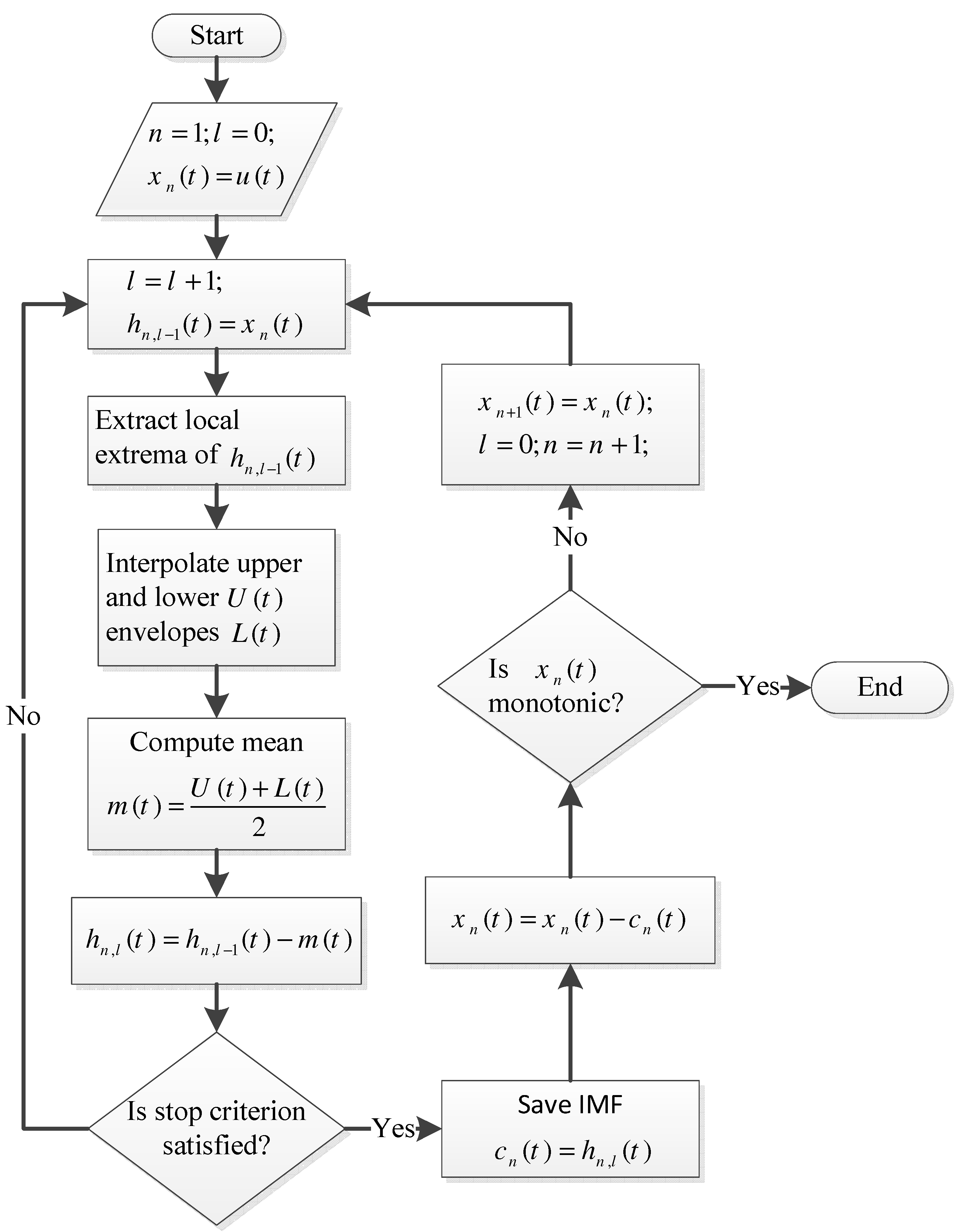
The subsequent IMF function can be obtained considering the ( n + 1 ) t h residual signal, x n + 1 ( t ) = u ( t ) j = 1 n c j ( t ) , as the new original signal, and the sifting process as explained above is repeated. The sifting process terminates as the desired number of IMFs ( m ) are obtained or the residual signal x n ( t ) is a monotonic signal (a signal with no extrema). The flowchart of the sifting process to calculate the IMFs is illustrated in Figure 6.
The instantaneous frequency, I F , of each IMF is obtained from [54]:
I F n ( t ) = d ( a r c t a n ( H [ c n ( t ) ] / c n ( t ) ) ) d t
where H [ . ] denotes the Hilbert transform operation. Huang et al. [42] introduced the Hilbert–Huang transform (HHT), in which the combination of the Hilbert transform and EMD is employed to determine the time–frequency representation or the instantaneous frequency of nonstationary signals. Furthermore, the obtained IMFs should be independent (orthogonal) to accurately represent the frequency content of the signal. The orthogonality of the decomposed IMFs may be examined by using the dot product formula as:
Orthogonality ( c i ( t ) , c j ( t ) ) = c i ( t ) . c j ( t ) , i j ; i , j = 1 , 2 , , n
where c i ( t ) and c j ( t ) are orthogonal if their dot product vanishes. The sifting process uses the cubic spline interpolation algorithm to estimate the upper and lower envelopes of the signal. This algorithm is of second-order smoothness (second-order derivable), which fits the local extrema points with adequate flexibility. Qin and Zhong [55] reported that fitting the local extrema points using the cubic spline interpolation algorithm may lead to over- and undershoot problems. These problems can shift the instantaneous mean of the upper and lower envelopes m ( t ) in the sifting process and may not satisfy the conditions required by the EMD algorithm.
Shulin et al. [56] proposed a Piecewise Cubic Hermite Interpolating Polynomial (PCHIP) to replace the cubic spline interpolation algorithm in the sifting process to eliminate the over- and undershoot problems. The PCHIP is of first-order smoothness with higher flexibility compared with the cubic spline, which is of second-order smoothness. It has been shown that the EMD algorithm based on PCHIP, namely, the improved EMD algorithm, provides more feature information than the cubic spline in reciprocating pump valves fault diagnosis.
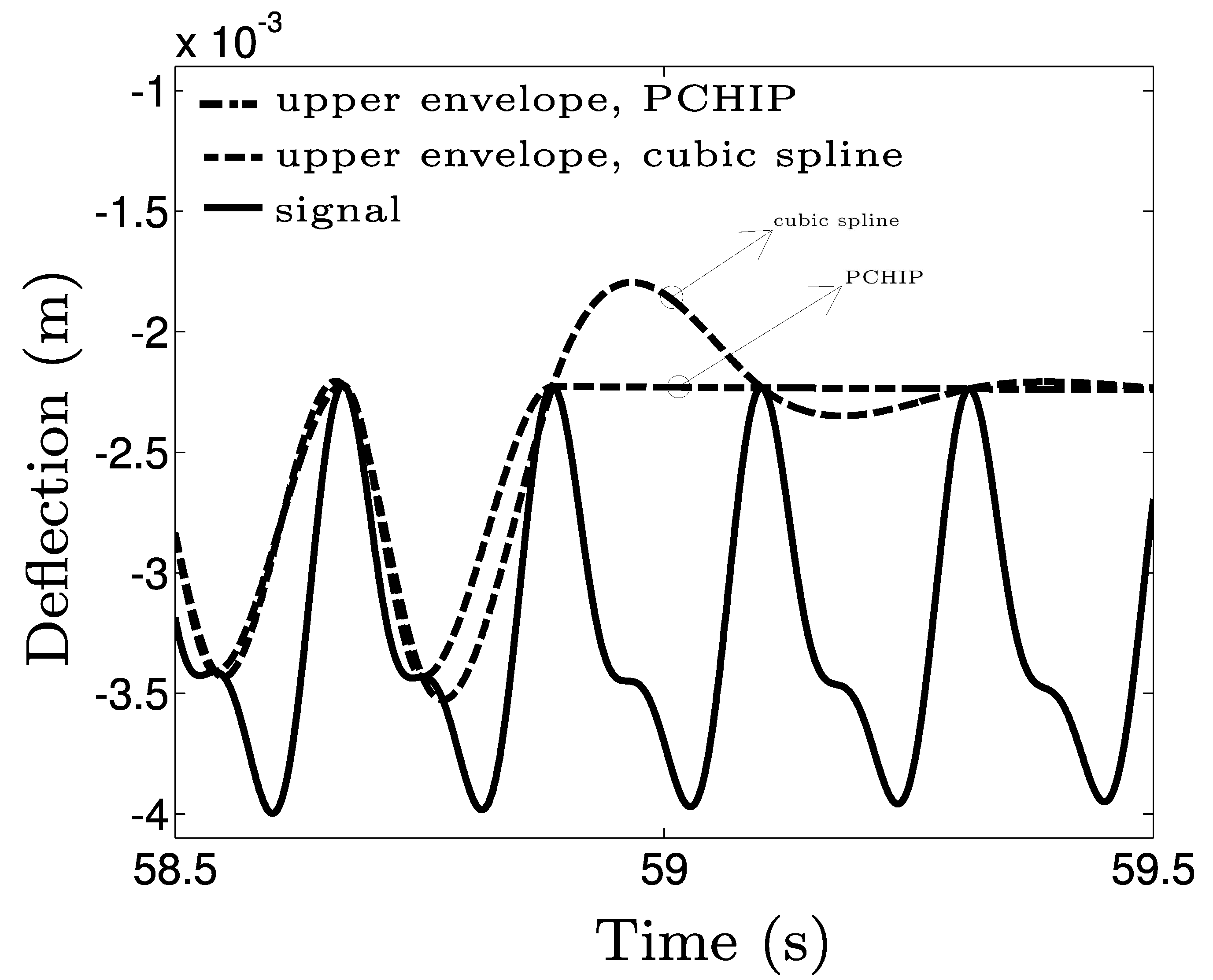
To better understand this effectiveness, both the cubic spline and the PCHIP algorithms have been used to obtain the upper envelope of the vertical transient response of a shaft–disc system with material properties and dimensions summarized in Table 1. The shaft rotates at speeds near to half of the first critical speed of the system, in which the second harmonic component of the vertical transient response is excited. Comparing the estimated upper envelopes derived using both the algorithms, illustrated in Figure 7, suggests that the over- and undershoot problems were eliminated using PCHIP.

4. Results and Discussion

A shaft supported on rigid-short bearings at both ends with a single disc mounted at its midspan and a breathing crack near the disc is considered for the analysis. The material properties and dimensions of the system model are identical to those given in Table 1. It is to be noted that a damping ratio of 0.055 is added to the system in this section. The shaft–disc system is modeled as a Jeffcott rotor and start-up vertical transient responses for different crack depths are obtained by solving the governing equations of motion, Equation (1). The shaft starts from rest and reaches the speed of 16.66 Hz (1000 rpm) with a constant acceleration of α r = 5 rad s 2 .
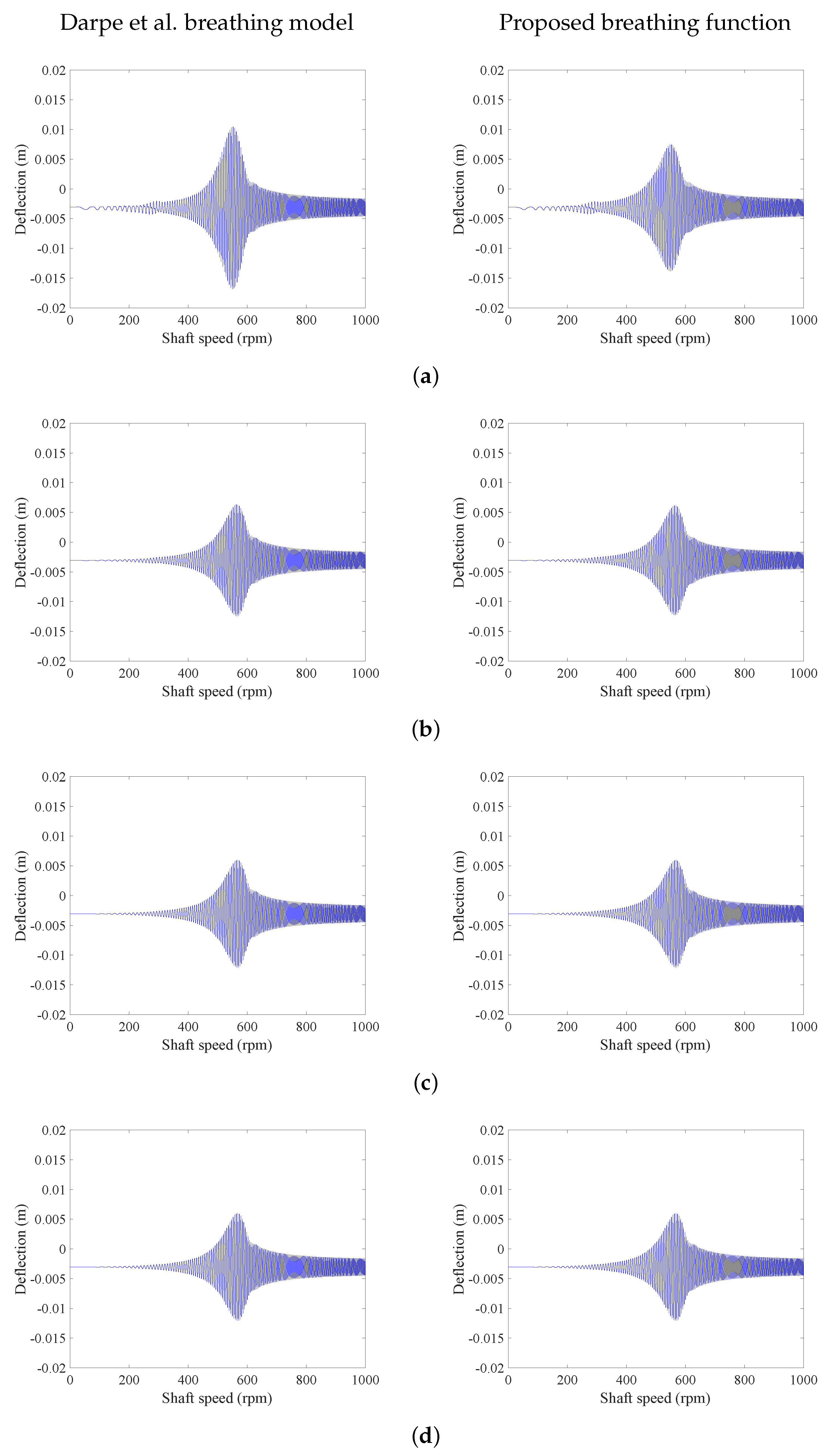
Figure 8 compares the vertical transient responses of the system with different crack depths passing through the first critical speeds using the breathing models proposed by Darpe et al. [4] and the alternate breathing function proposed in this study in Equation (14). The comparisons suggest that the two breathing functions yield nearly identical responses as the crack depth decreases. The differences in the responses due to two breathing functions are clearly evident for the large crack depth. This may be attributed to the fact that the proposed softly clipped cosine function gives a better estimation of the Darpe et al. [4] breathing model for small crack depths. The similarity of the responses was computed quantitatively considering the normalized Euclidean distance between two signals, as [57]:
distance ( u 1 t ( t ) , u 2 t ( t ) ) = 1 1 + | | u 1 t ( t ) u 2 t ( t ) | |
where u i t ( t ) ( i = 1 , 2 ) represents the transient lateral response and | | . | | returns the norm of the vector. The signals are exactly similar when the normalized Euclidean distance equals unity, and the similarity between the signals decreases as the normalized Euclidean distance between the two decreases.
Table 2 summarizes the computational costs and similarities of the obtained transient responses from both the breathing models using the normalized Euclidean distance between two signals, described in Equation (24). The computational costs are calculated when the simulation code developed in MATLAB is run on a personal computer with a 2.8 GHz Intel(R) Core (TM) i5 CPU and 8 GB RAM. The results show that the alternate breathing function reduces the computational cost by nearly 97% compared with that imposed by the Darpe et al. [4] breathing model. It is observed that the computational costs can be substantially reduced using the proposed softly clipped cosine function without sacrificing the accuracy in the presence of small-sized cracks.
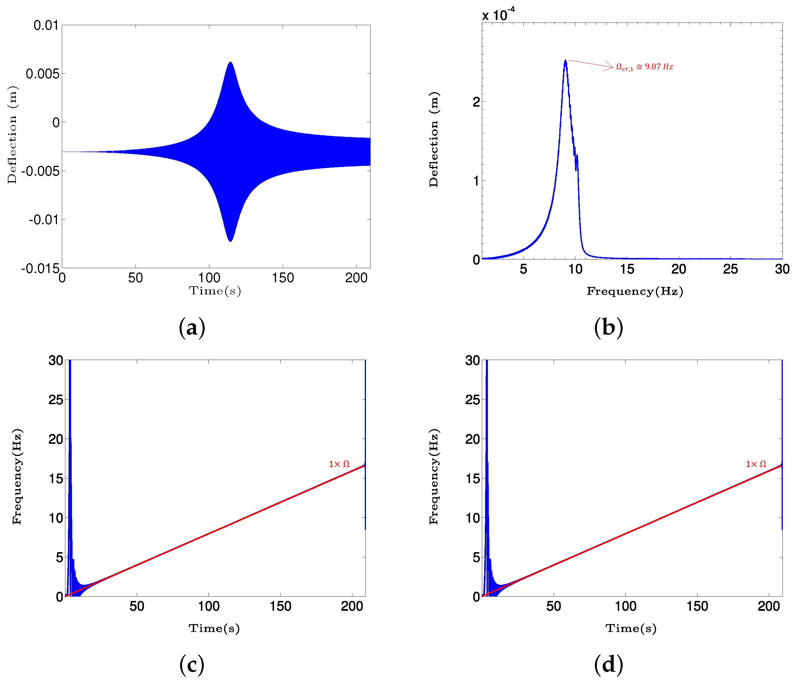
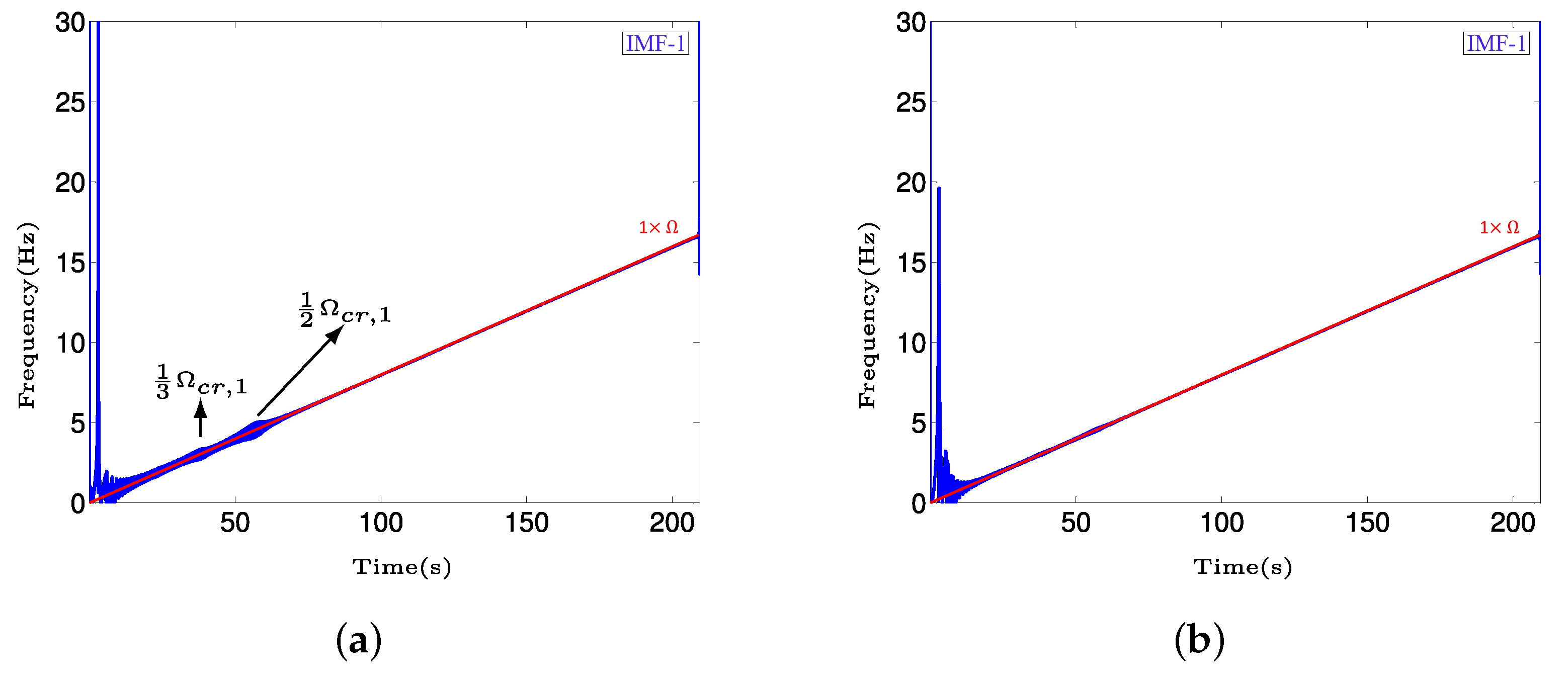
Figure 9 shows the transient response of the intact system in vertical direction and its frequency spectrum and time–frequency representations using HHT based on EMD and improved EMD techniques. These time–frequency representations are considered as the references for finding changes in vertical transient responses of the system in the presence of a crack. The vertical transient response amplitude in Figure 9a shows a peak at t = 114.4 s, corresponding to shaft speed Ω = 9.1 Hz. This shaft speed is considered as the first critical speed Ω c r , 1 of the intact system. The corresponding frequency spectrum in Figure 9b also shows the critical speed of the intact system as Ω c r , 1 = 9.07 Hz, while the corresponding peak amplitude is much lower than that shown in the time response. This may be attributed to the fact that Fourier transform is suitable only for stationary signals rather than transient (nonstationary) signals.
Figure 9c,d illustrate the instantaneous frequency of the vertical transient response obtained from HHT based on EMD and improved EMD methods, respectively. The results show that the instantaneous frequencies ( 1 × Ω ), computed based on both the methods, change linearly from 0 to 16.66 Hz (1000 rpm) as expected considering the linear relation for the shaft speed, Equation (15), in the transient response solution, as described in Section 2.2. These instantaneous frequencies are computed using Equation (22) and correspond to the first IMF based on EMD and improved EMD methods. It is noted that the unbalance force can only excite the first harmonic component of the transient response of the intact Jeffcott rotor. It must be mentioned that the undesirable high frequencies in the time–frequency representations near t = 0 s are attributed to numerical errors associated with the algorithms used.
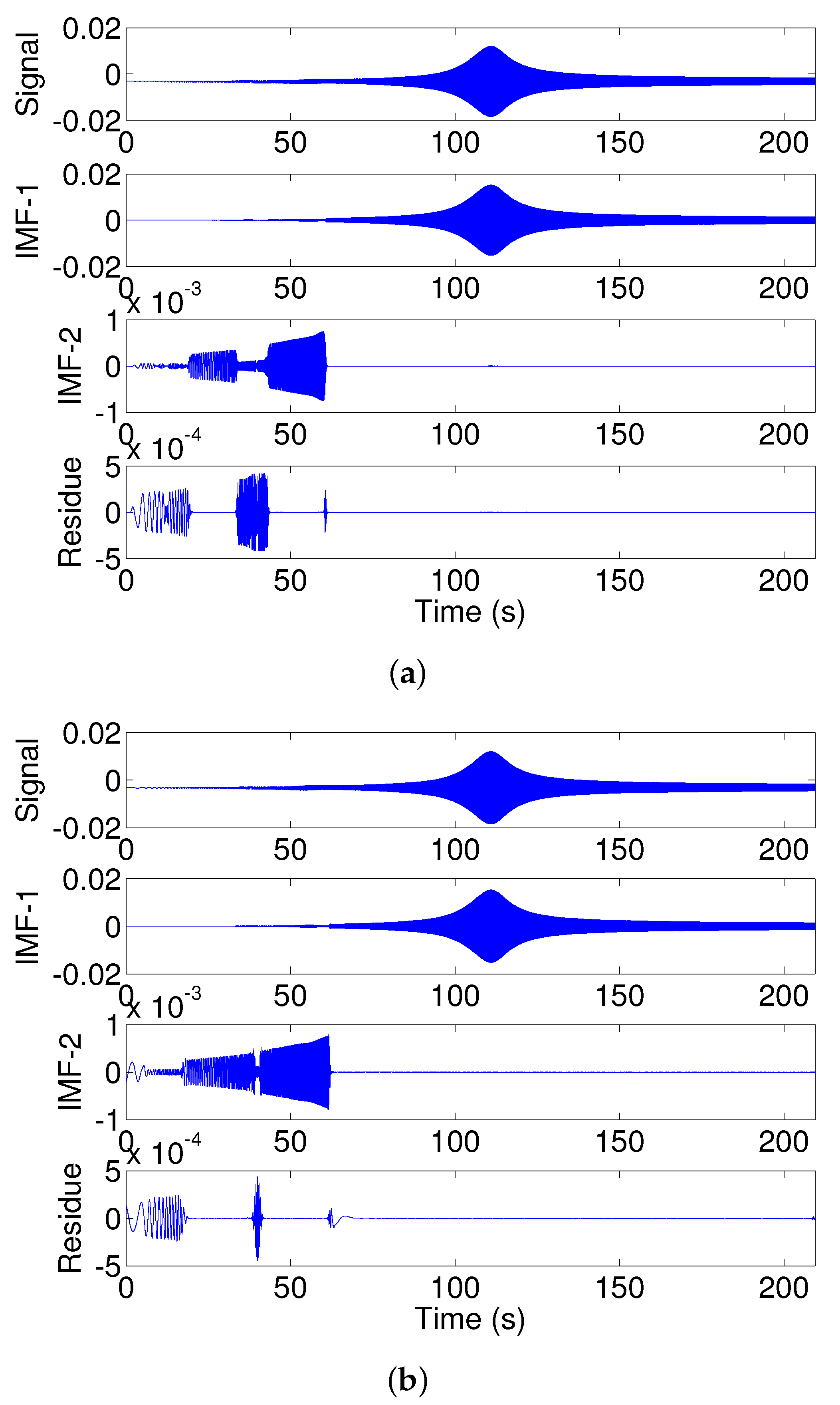
The decompositions of the vertical transient response of the system with a deep crack, ( μ = 1 ) , based on EMD and improved EMD algorithms, are shown in Figure 10. The vertical transient response has been obtained using the Darpe et al. [4] breathing model. The results show that the two algorithms could successfully decompose the transient signal into two IMFs. However, calculating the orthogonality between the obtained IMFs from each algorithm confirms that those obtained from the improved EMD show less dependency compared with those obtained from the EMD. The orthogonality between IMFs obtained from the improved EMD enhanced by 40% compared with those computed from the EMD algorithm. The orthogonality of the IMFs is examined using the dot product between IMFs, described in Equation (23). It is further shown that the enhanced orthogonality of the IMFs in the improved EMD method enable more accurate detection of small-sized cracks compared with the EMD method (Figure 11).
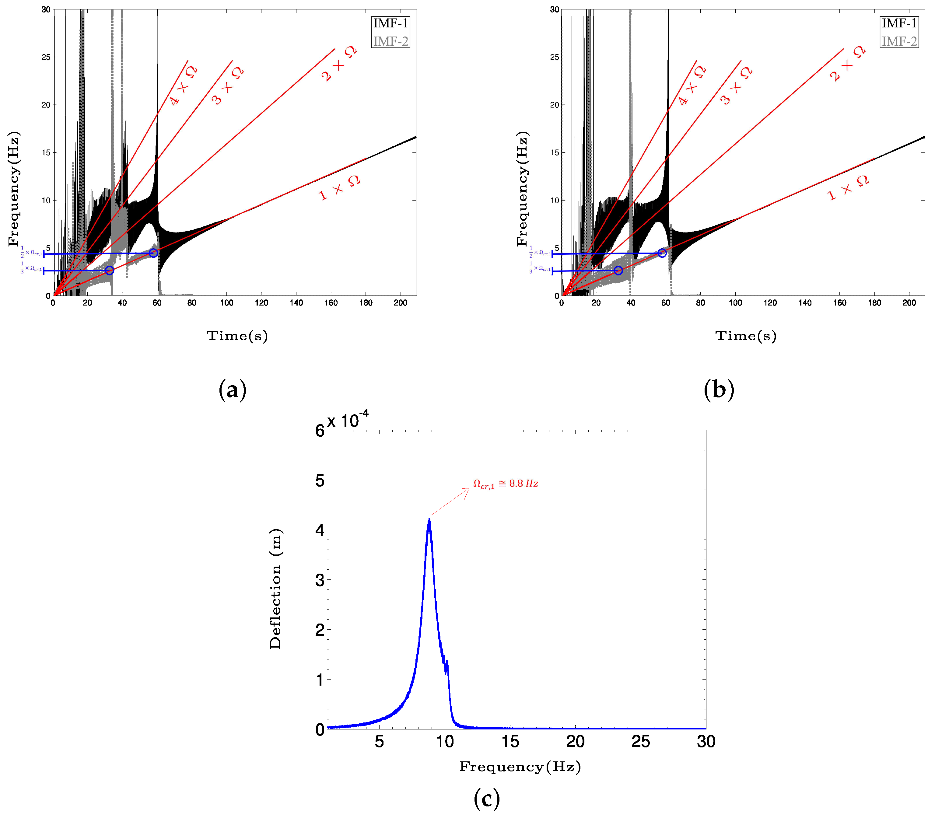
In both the EMD and improved EMD algorithms, frequencies in each segment of the nonstationary signal are extracted from higher to lower values. This means that the first IMF presents the highest frequency in each signal segment, while other IMFs consist of lower frequencies. For instance, in the decomposed vertical transient response of the cracked, ( μ = 1 ) , shaft–disc system into IMFs, shown in Figure 10a,b, the first IMF contains the first harmonic, and second, third, and forth superharmonic components, of the shaft speed ( 1 × , 2 × , 3 × and 4 × Ω ) . While the second IMF presents the second and third subharmonic components of the first critical speed ( 1 2 × Ω c r , 1 and 1 3 × Ω c r , 1 ).
This can be better realized in Figure 12a,b, which show the time–frequency representations of the first and second IMFs. Although the first IMF generated in both the EMD and improved EMD algorithms has clearly extracted the first harmonic and superharmonic components, it is observed that the second IMF generated in the improved EMD algorithm is better at distinguishing between the subharmonic components of the first critical speed. In other words, the second and third subharmonic components of the first critical speed ( 1 2 × Ω c r , 1 and 1 3 × Ω c r , 1 ) are clearly separated in time domain in the second IMF generated by the improved EMD algorithm along the 1 × Ω line, Figure 12a. However, these subharmonic components are not clearly separable in time domain in the second IMF generated by the EMD algorithm 1 × Ω line, Figure 12b. This advantage of the proposed improved EMD algorithm becomes more essential in the detection of smaller crack depths, as is discussed in Figure 13.
Deep cracks excite the superharmonic components of the transient response, which are detectable in time–frequency representations obtained from HHT based on EMD and improved EMD methods. Smaller crack depths, however, can not effectively excite the superharmonic components and yield only low-amplitude subcritical resonant peaks at 1 2 and 1 3 of the critical speed in the time–frequency representation of the vertical transient response. The detection of these small amplitude peaks strongly depends on the applied method to obtain the time–frequency representation of the vertical transient response. The improved EMD algorithm used in this study could enhance the performance of the crack detection based on changes in time–frequency representation compared with the EMD algorithm. This improvement could be achieved by decomposing the time signal into IMFs, where the degree of mutual orthogonality is enhanced by using a better interpolation algorithm in the sifting process.
The comparison between the frequency spectra of the system with a deep crack, shown in Figure 12c, and the intact system, shown in Figure 9b, confirms that the presence of the crack is not efficiently detectable from the frequency spectrum of the vertical transient response. The first critical speed of the intact system is 9.1 Hz, while for the system with a deep crack it decreases to 8.8 Hz, which is a relatively small change and difficult to recognize based on test data.
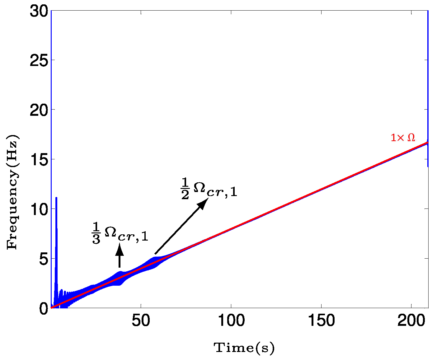
Figure 11 shows the time–frequency representations of the vertical transient response of the Jeffcott rotor with a small crack with normalized depth of μ = 0.2 , while the crack breathing behavior is modeled using the Darpe et al. [4] breathing model. The results show that the effect of subcritical resonant peaks due to the small crack on the instantaneous frequency of the first IMF are only observable in the time–frequency representation based on the improved EMD. Based on Equation (24), the similarity index between the first IMFs presented in Figure 11a,b, 0.645, is relatively low. This mathematically describes why the subcritical peaks are not visible in the first IMF obtained through the EMD algorithm. The smallest detectable normalized crack depths considering changes in time–frequency representation obtained from HHT based on EMD and improved EMD algorithms are 0.25 and 0.2, respectively. The figure shows changes in the time–frequency representations of the vertical transient response of the system near 1 2 and 1 3 of the first critical speed, which are obtained from the HHT based on the improved EMD algorithm.
The use of the proposed breathing function, described in Equation (14), also revealed the smallest detectable crack of μ = 0.2 in a shorter time with fewer computational efforts, as seen in Figure 13. Although the computational cost is typically not an issue in cracked Jeffcott rotor modeling, to introduce an agile online model-based crack detection monitoring based on the method described in this paper, it is essential to decrease the computation time. In online model-based monitoring, the result of measured signal processing is compared with those from the twin analytical model of the system to determine the depth of a potential crack in real time.

5. Conclusions and Future Work

In this study, the Hilbert–Huang transform based on an improved empirical mode decomposition is employed to obtain the time–frequency representation of the start-up vertical transient response of a shaft–disc system with transverse fatigue crack. The shaft–disc system is modeled as a Jeffcott rotor and the breathing behavior of the crack is modeled using the Darpe et al. [4] breathing model. The results show that the smallest detectable normalized crack depth using changes in the time–frequency representation of vertical transient response based on improved empirical mode decomposition is enhanced by 5% compared with those based on empirical mode decomposition. Furthermore, the proposed explicit breathing function could reduce the computational cost of the applied breathing model without sacrificing the accuracy of the crack breathing model in the case of small crack depths. This is essential in proceeding with the introduced method towards an online model-based monitoring for crack detection in rotating machinery. It is observed that the smallest detectable normalized crack depth using both the breathing functions is 0.2. The future work in this project is to experimentally evaluate the performance of the crack detection method and its robustness to the presence of noise.

Author Contributions

Conceptualization, H.K.; methodology, H.K.; software, H.K.; validation, H.K., R.S., and S.R.; formal analysis, H.K.; investigation, H.K.; resources, H.K.; data curation, H.K.; writing—original draft preparation, H.K.; writing—review and editing, R.S. and S.R.; visualization, H.K.; supervision, R.S. and S.R.; project administration, H.K.; funding acquisition, R.S. and S.R. All authors have read and agreed to the published version of the manuscript.

Funding

This research received external funding from the Natural Science and Engineering Research Council of Canada.

Data Availability Statement

Not applicable.

Acknowledgments

Support from Natural Science and Engineering Research Council of Canada is gratefully acknowledged.

Conflicts of Interest

The authors declare no conflict of interest.

Nomenclature

The following nomenclatures are used in this manuscript:
acrack depth
Cexternal damping coefficient
c n ( t ) n t h Intrinsic Mode Function, IMF
Dshaft diameter
Eshaft modulus of elasticity
f ( t ) crack breathing function
G r shaft compliance matrix in the rotating system
gacceleration due to gravity
g ξ ξ , g η ξ , g ξ η , g η η compliance elements of the cracked shaft cross-section
in the rotating coordinates
H [ . ] Hilbert transform operation
Ishaft area moment of inertia about x-axis
I F n ( t ) instantaneous frequency of the n t h IMF
J ( α ) strain energy density function due to the crack
K I , K Q ξ I , K Q η I stress intensity factors
K r shaft stiffness matrix in the rotating system
k ξ ξ , k η ξ , k ξ η , k η η stiffness elements of the cracked shaft cross-section
in the rotating coordinates
L ( t ) lower envelope of the original signal
L 1 disc location on the shaft
L 2 shaft length
Mdisc mass
m ( t ) instantaneous mean of the original signal
Q ξ , Q η forces acting on the shaft cracked cross-area
Rshaft radius
U ( t ) upper envelope of the original signal
U c additional strain energy due to the crack
u ( t ) lateral (vertical and horizontal) response of the shaft, original signal
u i additional deflections due to the crack ( i = ξ , η )
x m ( t ) m t h residual signal
Ω shaft rotational speed
ω whirling speed of the shaft
α r shaft acceleration rate
ε unbalance disc eccentricity
θ ( t ) shaft rotational angle
τ short-time Fourier transform parameter
μ = a R normalized crack depth

References

  1. Zeng, J.; Chen, K.; Ma, H.; Duan, T.; Wen, B. Vibration response analysis of a cracked rotating compressor blade during run-up process. Mech. Syst. Signal Process. 2019, 118, 568–583. [Google Scholar] [CrossRef]
  2. Wu, J.; Zhang, X.; Li, B. A study on vibration component separation of a rotor system during startup and its application in fault diagnosis. Meas. Sci. Technol. 2019, 30, 095104. [Google Scholar] [CrossRef]
  3. Sawicki, J.; Wu, X.; Baaklini, G.; Gyekenyesi, A. Vibration-based crack diagnosis in rotating shafts during acceleration through resonance. In Nondestructive Evaluation and Health Monitoring of Aerospace Materials and Composites II; SPIE: Bellingham, WA, USA, 2003; Volume 5046, pp. 1–10. [Google Scholar]
  4. Darpe, A.; Gupta, K.; Chawla, A. Transient response and breathing behaviour of a cracked Jeffcott rotor. J. Sound Vib. 2004, 272, 207–243. [Google Scholar] [CrossRef]
  5. Papadopoulos, C.; Dimarogonas, A. Coupled longitudinal and bending vibrations of a rotating shaft with an open crack. J. Sound Vib. 1987, 117, 81–93. [Google Scholar] [CrossRef]
  6. Darpe, A.; Gupta, K.; Chawala, A. Dynamics of a two-crack rotor. J. Sound Vib. 2003, 259, 649–675. [Google Scholar] [CrossRef] [Green Version]
  7. Eshlemen, R.; Eubanks, R. On the critical speeds of a continuous shaft-disk system. J. Eng. Ind. 1967, 89, 645–652. [Google Scholar] [CrossRef]
  8. Jun, O.; Kim, J. Free bending vibration of a multi-step rotor. J. Sound Vib. 1999, 224, 625–642. [Google Scholar] [CrossRef]
  9. Yamamoto, T.; Ishida, Y. Linear and Nonlinear Rotordynamics: A Modern Treatment with Applications, 1st ed.; Wiley and Sons: Hoboken, NJ, USA, 2001. [Google Scholar]
  10. Chasalevris, A.; Papadopoulos, C. A continuous model approach for cross-coupled bending vibrations of a rotor-bearing system with a transverse breathing crack. Mech. Mach. Theory 2009, 44, 1176–1191. [Google Scholar] [CrossRef]
  11. Sinou, J.J.; Denimal, E. Reliable crack detection in a rotor system with uncertainties via advanced simulation models based on kriging and Polynomial Chaos Expansion. Eur. J. Mech. Solids 2022, 92, 104451. [Google Scholar] [CrossRef]
  12. Fu, C.; Xu, Y.; Yang, Y.; Lu, K.; Gu, F.; Ball, A. Dynamics analysis of a hollow-shaft rotor system with an open crack under model uncertainties. Commun. Nonlinear Sci. Numer. Simulations 2020, 83, 105102. [Google Scholar] [CrossRef]
  13. Sinou, J.; Lees, A. A non-linear study of a cracked rotor. Eur. J. Mech. A Solids 2007, 26, 152–170. [Google Scholar] [CrossRef] [Green Version]
  14. AL-Shudeifat, M.; Butcher, E. New breathing functions for the transverse breathing crack of the cracked rotor system: Approach for critical and subcritical harmonic analysis. J. Sound Vib. 2011, 330, 526–544. [Google Scholar] [CrossRef]
  15. Sekhar, A. Multiple cracks effects and identification. Mech. Syst. Signal Process. 2008, 22, 845–878. [Google Scholar] [CrossRef]
  16. AL-Shudeifat, M.; Butcher, E.; Stern, C. General harmonic balance solution of a cracked rotor-bearing-disk system for harmonic and sub-harmonic analysis: Analytical and experimental approach. Int. J. Eng. Sci. 2010, 48, 921–935. [Google Scholar] [CrossRef]
  17. Friswell, M.; Penny, J. Crack modeling for structural health monitoring. Struct. Health Monit. 2002, 1, 139–148. [Google Scholar] [CrossRef]
  18. Lees, A.; Friswell, M. The vibration signature of chordal cracks in asymmetric rotors. In Proceedings of the 19th International Modal Analysis Conference (IMAC), Kissimmee, FL, USA, 5–8 February 2001; pp. 1–6. [Google Scholar]
  19. Plaut, R.; Andruet, R.; Suherman, S. Behavior of a cracked rotating shaft during passage through a critical speed. J. Sound Vib. 1994, 173, 577–589. [Google Scholar] [CrossRef]
  20. Ramesh Babu, T.; Srikanth, S.; Sekhar, A. Hilbert–Huang transform for detection and monitoring of crack in a transient rotor. Mech. Syst. Signal Process. 2008, 22, 905–914. [Google Scholar] [CrossRef]
  21. Jun, O.; Eun, H.; Earmme, Y.; Lee, C. Modeling and vibration analysis of a simple rotor with a breathing crack. J. Sound Vib. 1992, 155, 273–290. [Google Scholar] [CrossRef]
  22. Zou, J.; Chen, J.; Niu, J.; Cheng, Z. Application of the Wigner–Ville distribution to identification of a cracked rotor. Proc. Inst. Mech. Eng. Part C J. Mech. Eng. Sci. 2003, 217, 551–556. [Google Scholar] [CrossRef]
  23. Sawicki, J.; Sen, A.; Litak, G. Multiresolution wavelet analysis of the dynamics of a cracked rotor. Int. J. Rotating Mach. 2009, 2009, 265198. [Google Scholar] [CrossRef] [Green Version]
  24. Papadopoulos, C. The strain energy release approach for modeling cracks in rotors: A state of the art review. Mech. Syst. Signal Process. 2008, 22, 763–789. [Google Scholar] [CrossRef]
  25. Darpe, A.; Gupta, K.; Chawla, A. Coupled bending, longitudinal and torsional vibrations of a cracked rotor. J. Sound Vib. 2004, 269, 33–60. [Google Scholar] [CrossRef]
  26. Sinou, J. Detection of cracks in rotor based on the 2× and 3× super-harmonic frequency components and the crack–unbalance interactions. Commun. Nonlinear Sci. Numer. Simul. 2008, 13, 2024–2040. [Google Scholar] [CrossRef] [Green Version]
  27. Sekhar, A. Vibration characteristics of a cracked rotor with two open cracks. J. Sound Vib. 1999, 223, 497–512. [Google Scholar] [CrossRef]
  28. Dimarogonas, A.; Papadopoulos, C. Vibration of cracked shafts in bending. J. Sound Vib. 1983, 91, 583–593. [Google Scholar] [CrossRef]
  29. Mayes, I.; Davies, W. Analysis of the response of a multi-rotor-bearing system containing a transverse crack in a rotor. J. Vib. Acoust. Stress. Reliab. Des. 1984, 106, 139–145. [Google Scholar] [CrossRef]
  30. Bachschmid, N.; Pennacchi, P.; Vania, A. Identification of multiple faults in rotor systems. J. Sound Vib. 2002, 254, 327–366. [Google Scholar] [CrossRef] [Green Version]
  31. Sinou, J.; Lees, A. The influence of cracks in rotating shafts. J. Sound Vib. 2005, 285, 1015–1073. [Google Scholar] [CrossRef] [Green Version]
  32. Gasch, R. A survey of the dynamic behavior of a simple rotating shaft with a transverse crack. J. Sound Vib. 1993, 106, 313–332. [Google Scholar] [CrossRef]
  33. Sekhar, A. On-line rotor fault identification by combined model and signal based approach. Noise Vib. Worldw. 2004, 35, 16–30. [Google Scholar] [CrossRef]
  34. Pennacchi, P.; Bachschmid, N.; Vania, A. A model-based identification method of transverse cracks in rotating shafts suitable for industrial machines. Mech. Syst. Signal Process. 2006, 20, 2112–2147. [Google Scholar] [CrossRef] [Green Version]
  35. Papadopoulos, C.; Dimarogonas, A. Stability of cracked rotors in the coupled vibration mode. J. Vib. Acoust. Stress. Reliab. Des. 1988, 110, 356–360. [Google Scholar] [CrossRef]
  36. Sampaio, D.L.; Nicoletti, R. Detection of cracks in shafts with the Approximated Entropy algorithm. Mech. Syst. Signal Process. 2016, 72, 286–302. [Google Scholar] [CrossRef]
  37. Nicoletti, R.; Cavalini, A.A.; Steffen, V. Detection of Cracks in Rotating Shafts by Using the Combination Resonances Approach and the Approximated Entropy Algorithm. Shock Vib. 2018, 2018, 4094631. [Google Scholar] [CrossRef] [Green Version]
  38. Sekhar, A.; Prabhu, B. Condition monitoring of cracked rotors through transient response. Mech. Mach. Theory 1988, 33, 1167–1175. [Google Scholar] [CrossRef]
  39. Sekhar, A. Detection and monitoring of crack in a coast-down rotor supported on fluid film bearings. Tribol. Int. 2004, 37, 279–287. [Google Scholar] [CrossRef]
  40. Sekhar, A. Crack detection through wavelet transform for a run-up rotor. J. Sound Vib. 2003, 259, 461–472. [Google Scholar] [CrossRef]
  41. Lei, Y.; Lin, J.; He, Z.; Zuo, M. A review on empirical mode decomposition in fault diagnosis of rotating machinery. Mech. Syst. Signal Process. 2013, 35, 108–126. [Google Scholar] [CrossRef]
  42. Huang, N.; Shen, Z.; Long, S.; Wu, M.; Shih, E.; Zheng, Q.; Yen, N.; Tung, C.; Liu, H. The empirical mode decomposition method and the Hilbert spectrum for non-stationary time series analysis. Proc. R. Soc. Lond. A 1998, 454, 903–995. [Google Scholar] [CrossRef]
  43. Guo, D.; Peng, Z. Vibration analysis of a cracked rotor using Hilbert–Huang transform. Mech. Syst. Signal Process. 2007, 21, 3030–3041. [Google Scholar] [CrossRef]
  44. Harish Chandra, N.; Sekhar, A. Fault detection in rotor bearing systems using time frequency techniques. Mech. Syst. Signal Process. 2016, 72–73, 105–133. [Google Scholar] [CrossRef]
  45. Teyi, N.; Singh, S. A Decadal Review of Various Modelling and Analysis of Cracked Rotors. Procedia Struct. Integr. 2022, 39, 333–346. [Google Scholar] [CrossRef]
  46. Chen, G.; Wang, Z. A signal decomposition theorem with Hilbert transform and its application to narrowband time series with closely spaced frequency components. Mech. Syst. Signal Process. 2012, 28, 258–279. [Google Scholar] [CrossRef]
  47. Rato, R.; Ortigueira, M.; Batista, A. On the HHT, its problems, and some solutions. Mech. Syst. Signal Process. 2008, 22, 1374–1394. [Google Scholar] [CrossRef] [Green Version]
  48. He, Z.; Shen, Y.; Wang, Q. Boundary extension for Hilbert–Huang transform inspired by gray prediction model. Signal Process. 2012, 92, 685–697. [Google Scholar] [CrossRef]
  49. Xun, J.; Yan, S. A revised Hilbert–Huang transformation based on the neural networks and its application in vibration signal analysis of a deployable structure. Mech. Syst. Signal Process. 2008, 22, 1705–1723. [Google Scholar] [CrossRef]
  50. Zhu, X.; Hu, J.; Lv, S. Comprehensive evaluation study on the methods for restraining the end effect in EMD. Inf. Technol. J. 2013, 12, 3870–3874. [Google Scholar]
  51. Hawley, S.; Atlas, L.; Chizeck, H. Some properties of an empirical mode type signal decomposition algorithm. IEEE Signal Process. Lett. 2010, 17, 24–27. [Google Scholar] [CrossRef]
  52. Roy, A.; Doherty, J. Raised cosine filter–based empirical mode decomposition. IET Signal Process. 2011, 5, 121–129. [Google Scholar] [CrossRef]
  53. Wu, Z.; Huang, N. Ensemble empirical mode decomposition: A noise-assisted data analysis method. Adv. Adapt. Data Anal. 2009, 1, 1–41. [Google Scholar] [CrossRef]
  54. Wang, Y.; He, Z.; Zi, Y. A comparative study on the local mean decomposition and empirical mode decomposition and their applications to rotating machinery health diagnosis. J. Vib. Acoust. 2010, 132, 021010. [Google Scholar] [CrossRef]
  55. Qin, S.; Zhong, Y. A new envelope algorithm of Hilbert–Huang Transform. Mech. Syst. Signal Process. 2006, 20, 1941–1952. [Google Scholar] [CrossRef]
  56. Shulin, L.; Haifeng, Z.; Hui, W.; Rui, M. Application of improved EMD algorithm for the fault diagnosis of reciprocating pump valves with spring failure. In Proceedings of the 9th International Symposium on ISSPA, Sharjah, United Arab Emirates, 12–15 February 2007; pp. 1–4. [Google Scholar]
  57. Arlot, S.; Celisse, A. A survey of cross–validation procedures for model selection. Stat. Surv. 2010, 4, 40–79. [Google Scholar] [CrossRef]
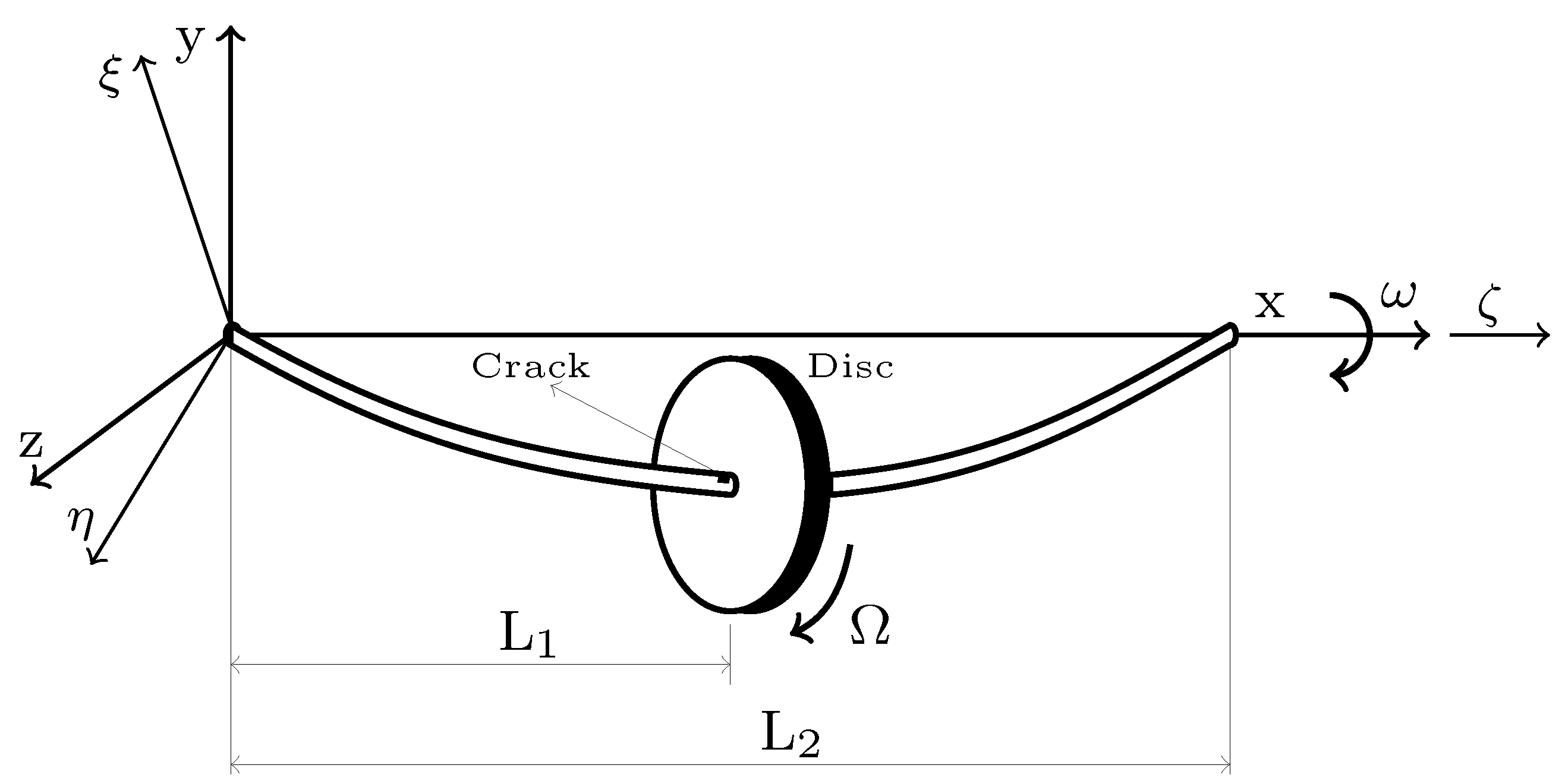
Figure 1. A Jeffcott rotor model with a single crack near the disc in the stationary coordinate ( x , y , z ) and rotating coordinate ( ζ , ξ , η ) frames.
Vibration 05 00023 g001
Figure 2. Stationary ( x , y , z ) and rotating ( ζ , ξ , η ) coordinate systems [21].
Vibration 05 00023 g002
Figure 3. Crack cross-section geometry in rotating ( ζ , ξ , η ) coordinate system, (a) fully open crack, (b) partially open–closed crack [4].
Vibration 05 00023 g003
Figure 4. Comparison of the proposed breathing function with that reported by Darpe et al. [4] breathing model.
Vibration 05 00023 g004
Figure 5. The transient lateral response solution flowchart.
Vibration 05 00023 g005
Figure 6. Implementation of the empirical mode decomposition algorithm.
Vibration 05 00023 g006
Figure 7. Comparison of the upper envelopes in the sifting process based on cubic spline and PCHIP for vertical transient response of a cracked Jeffcott rotor at shaft speeds close to half of its first critical speed.
Vibration 05 00023 g007
Figure 8. Vertical transient response of the Jeffcott rotor system with normalized crack depths of (a) μ = 1 ; (b) μ = 0.5 ; (c) μ = 0.2 ; and (d) μ = 0.1 using the Darpe et al. [4] breathing model and alternate breathing function (softly clipped cosine function).
Vibration 05 00023 g008
Figure 9. Intact Jeffcott rotor vertical transient response; (a) time response; (b) Fourier spectrum; time–frequency representation based on (c) EMD and (d) improved EMD.
Vibration 05 00023 g009
Figure 10. Decomposition of the vertical transient response of the system with a deep crack, ( μ = 1 ) , based on (a) improved EMD and (b) EMD algorithms, the shaft speed changes from 0 to 16.66 Hz (1000 rpm) with a constant acceleration rate of a r = 0.5 rad s 2 .
Vibration 05 00023 g010
Figure 11. Time–frequency representations of the vertical transient response of the system with a small crack, ( μ = 0.2 ) using HHT based on (a) improved EMD and (b) EMD algorithms.
Vibration 05 00023 g011
Figure 12. Time–frequency representations of the vertical transient response of the system with a deep crack, ( μ = 1 ) , using HHT based on (a) improved EMD, (b) EMD algorithms (solid line represents the instantaneous frequency of the first IMF and dotted line represents the instantaneous frequency of the second IMF), and (c) Fourier spectrum.
Vibration 05 00023 g012
Figure 13. Time–frequency representations of the vertical transient response of the system with a small crack, ( μ = 0.2 ) , using HHT based on improved EMD, and the crack is modeled using the proposed breathing function in this study.
Vibration 05 00023 g013
Table 1. Material properties and dimensions of the shaft–disc system.
DescriptionValue
Modulus of elasticity (Pa) 69 × 109
Modulus of rigidity (Pa) 34 × 109
Shaft diameter (m)0.01905
Shaft length (m)1.27
Shaft density (kg/m3)2700
Disc density (kg/m3)2700
Disc diameter (m)0.1524
Disc thickness (m)0.0254
Normalized disc location0.5
Unbalance mass (kg)0.01
Unbalance eccentricity (m)0.0508
Table 2. Transient responses deviations and their computational costs with different normalized crack depths μ using the Darpe et al. [4] breathing model and proposed breathing function.
Normalized
Crack Depth
μ
Computational Cost (s)Transient Responses
Similarity
Proposed
Breathing Function
Darpe et al. [4]
Breathing Model
112.866446.9420.9296
0.512.319408.9070.9943
0.212.673369.7020.9995
0.112.364341.0600.9999
Publisher’s Note: MDPI stays neutral with regard to jurisdictional claims in published maps and institutional affiliations.