1. Introduction
The wheel–rail contact dynamics of trains in motion are a complex phenomenon that requires in-depth analysis. Currently, this analysis is expressed by numerical modeling in some available commercial software with the computational ability to analyze complex problems. For instance, Thomson utilized a 2D model to examine the transient vibration characteristics of a train wheel [
1]. Sato et al. [
2] investigated the vibration and sound radiation characteristics of rail wheels by conducting experiments and validating their results through modeling the wheel and performing Finite Element Analysis (FEA). Zhong et al. [
3] studied the vibration and sound radiation of a rotating train wheel subjected to vertical harmonic wheel–rail force (with and without rotation) using 2.5DFinit Element Method (FEM) to calculate the wheel vibration characteristics and validating their findings with the experimental results. They concluded that the wheel rotation speed splits most peaks of the vertical receptance at the wheel–rail contact point [
4]. Mazilu [
5] examined the radial and axial wheel vibration by using both theoretical and experimental approaches and concluded that larger resonance peaks of frequencies at radial excitation would start at frequencies larger than 1500 Hz. It was also observed that radial excitation would experience higher amplitude resonance peaks than lateral excitation.
It is known that vibrations in rails are caused by vehicle force on the railroad tracks from the wheels and from irregularities at the wheel–rail interference (corrugation). As a prevalent consequence, rail–wheel vibration can result in rolling noise, shorten the life cycle of the rolling surfaces from wear or cause discomfort to passengers, tonal noise and damage to the vehicle’s structural components. Additionally, excessive vibration on a rail wheel has long been acknowledged to be caused by rail wheel corrugation [
3,
4,
5,
6,
7]. Balekwa and Kallon [
8] investigated resonance frequencies via experimental and Finite Element Modal Analysis (FEMA) of the class D39 200 locomotive wheelset, correlating their results with corrugation frequencies around the track curves [
9]. The locomotive class D39 200 is normally operated on the Belfast to Steelpoort railway line. This study highlighted how the locomotive experiences rail corrugation when passing through track curves, resulting in excessive rail wheel vibrations [
10,
11,
12].
The main focus of the present manuscript was to develop a design procedure that allowed for mitigating locomotive wheel resonance during radial and lateral excitations through parametric modeling of viscoelastic layers. The originality of the study lies in the optimization method adopted. Through the application of computational methods and the experimental characterization of the damping, this allowed for finding the optimal geometry of the layers that minimized wheel vibrations in a wide range of frequencies.
In short, three viscoelastic damping layers were parametrically designed to be mounted on the locomotive wheel structure, being in contact at a point where the structure experiences high deformation in such a way that the viscoelastic damping layer cannot but dissipate energy as much as possible.
A case study of the locomotive class D39 200 wheel offered tangible results to support the methodology by validating it with experimental data. The resonance amplitude peaks observed in the wheels of this locomotive [
8,
9,
10,
11,
12,
13] were damped using this new viscoelastic passive damping design technique.
To be precise, the viscoelastic damping layer, which is applied on structures to mitigate vibrations, can be either an unconstrained (free) damping layer or a constrained damping layer. The difference is that a constrained damping layer consists of a steel or aluminum layer with a viscoelastic high-damping polymer sheet mounted between the structure and steel, while an unconstrained (free) damping layer is used instead when the viscoelastic high-damping polymer is mounted on the structure [
14,
15,
16]. It is clear that the advantages of viscoelastic damping can be identified in the material properties, which consist of elastic and viscous characteristics at the same time.
Lopez [
17] studied a wheel fitted with a steel rod ring inside the groove cut under the rim. The motion between the wheel and ring reduced vibration gradually through friction and interference by converting the vibration into heat. The conclusion was that by also increasing the ring damper mass mounted on the wheel, the damping efficiency on the wheel increased. The problem is that the theoretical design mechanism of this type of damping procedure, called a ring damper, is still not well understood [
18]. As an advantage, ring dampers are simple and cost-effective compared with other wheel dampers.
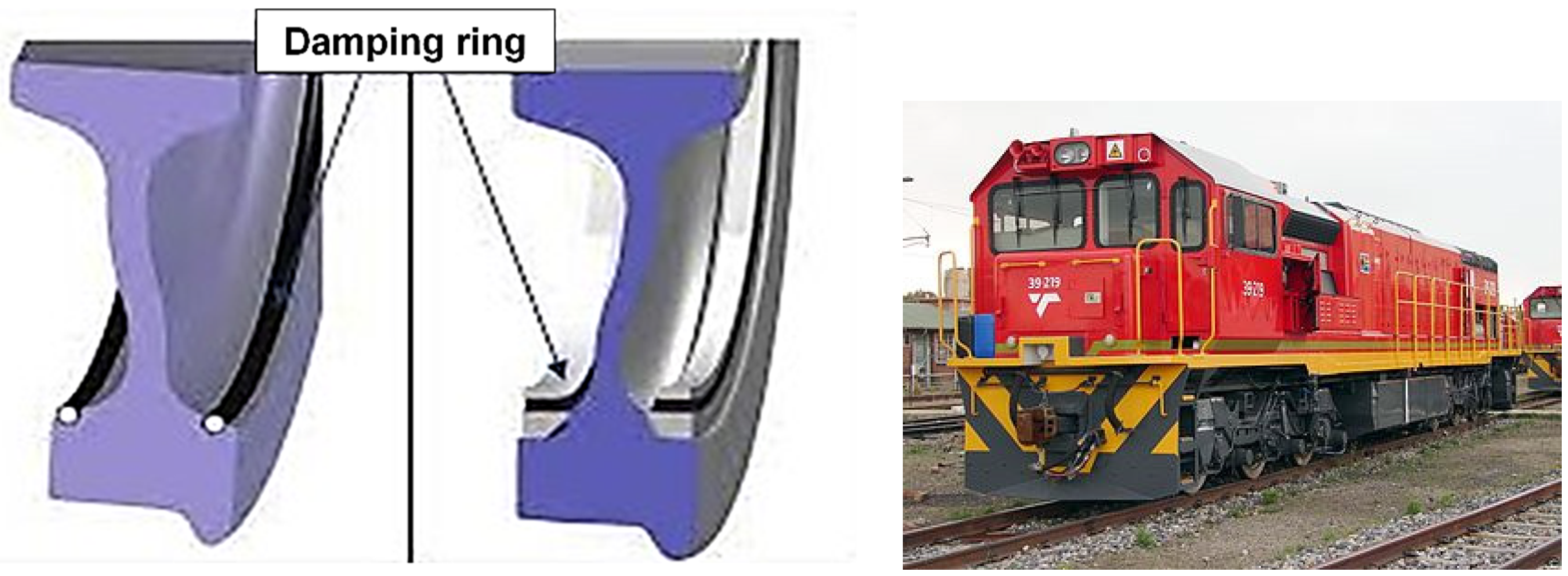
Figure 1 shows the rail wheel mounted with a damping ring under the rim of both sides of the wheel [
19].
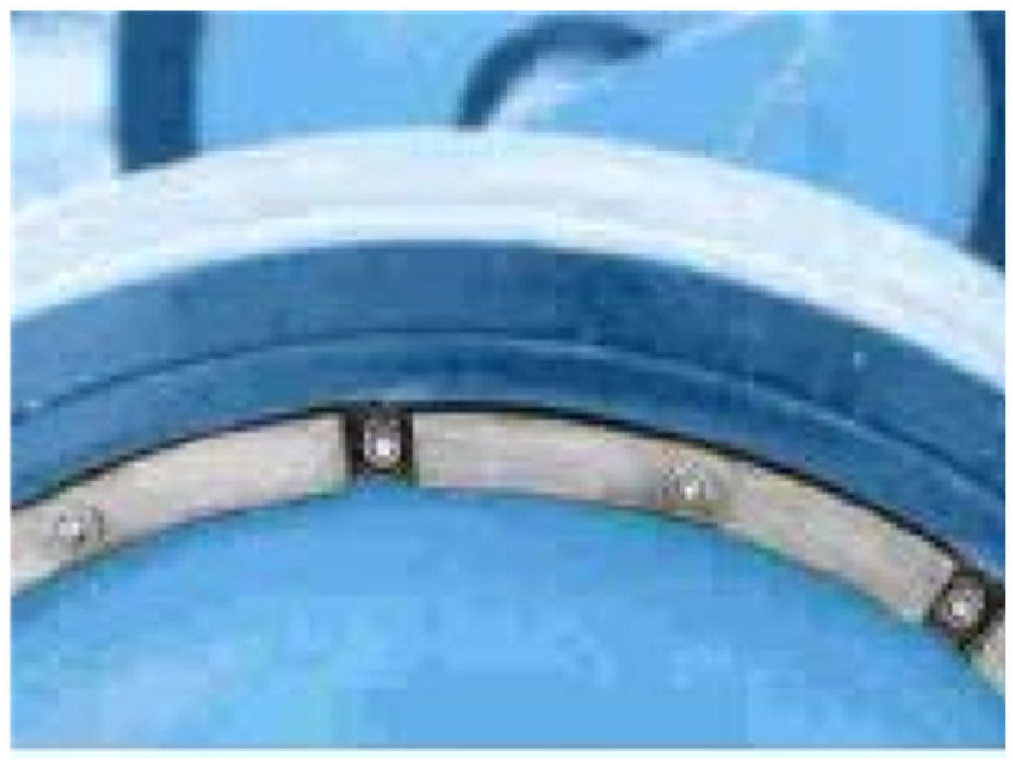
It should be noted that many researchers have investigated tuned mass dampers (TMDs) for different applications like rail wheels, beams and railway bridges [
20,
21,
22]. A TMD, first developed by Frahm in 1909 [
23,
24], is a device having a mass–spring–damper system integral to the structure to reduce the dynamic response. Later in his book on mechanical vibrations, Den Hartog used a tuned mass damper to mitigate vibrations in systems [
25]. The frequency of the damper is tuned to a structural frequency so that during excitation, the TMD resonates out of phase with the structural motion, reducing unwanted energy depending on the modal displacement in the system. The mass damper consists of a viscous elastic layer which can turn the vibration into heat energy [
26] (
Figure 2).
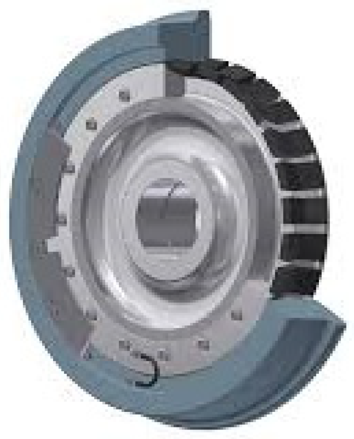
Suarez et al. [
27] compared the vibration and noise of resilient and solid monobloc railway wheels on underground lines. Based on their results, the resilient wheels demonstrated better performance. It is the resilient wheel which is commonly designed for light transit systems in order to mitigate the dynamic vibration of the wheel, rolling noise produced by wheel–rail contact and wheel squeal noise on sharp curves [
28] (
Figure 3).
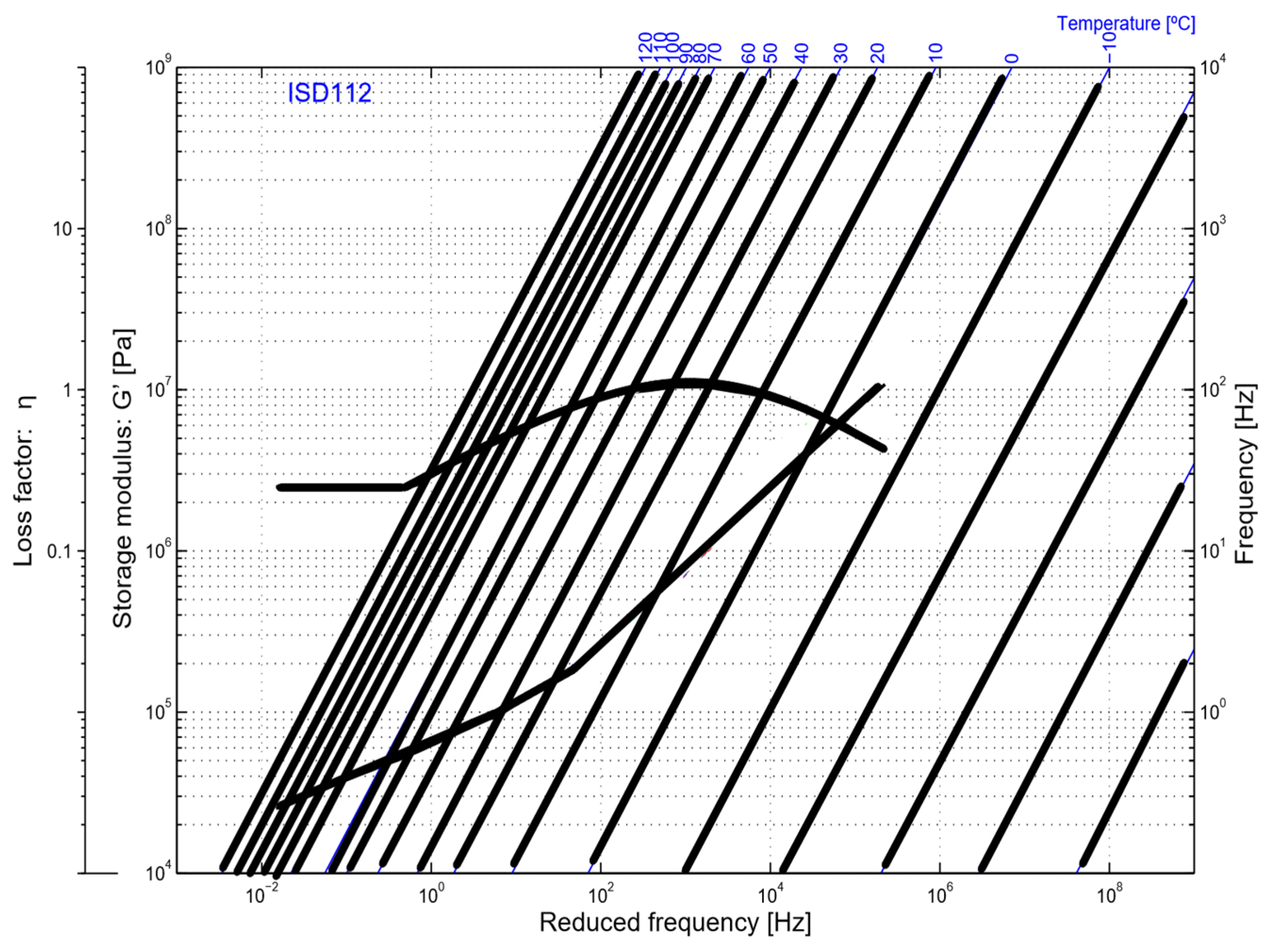
In light of these considerations, in the present study, the viscoelastic damping layer material 3M ISD112 [
29] was chosen because of its widespread use and commercial availability [
30,
31,
32,
33].
Introduction excluded, the manuscript is organized into four sections. In the first section, the experimental and numerical analysis methodology are illustrated. In the second section, the principal results obtained for different viscoelastic layer positions and arrangements are discussed. The final considerations and conclusions are discussed in sections three and four, respectively.
2. Materials and Methods
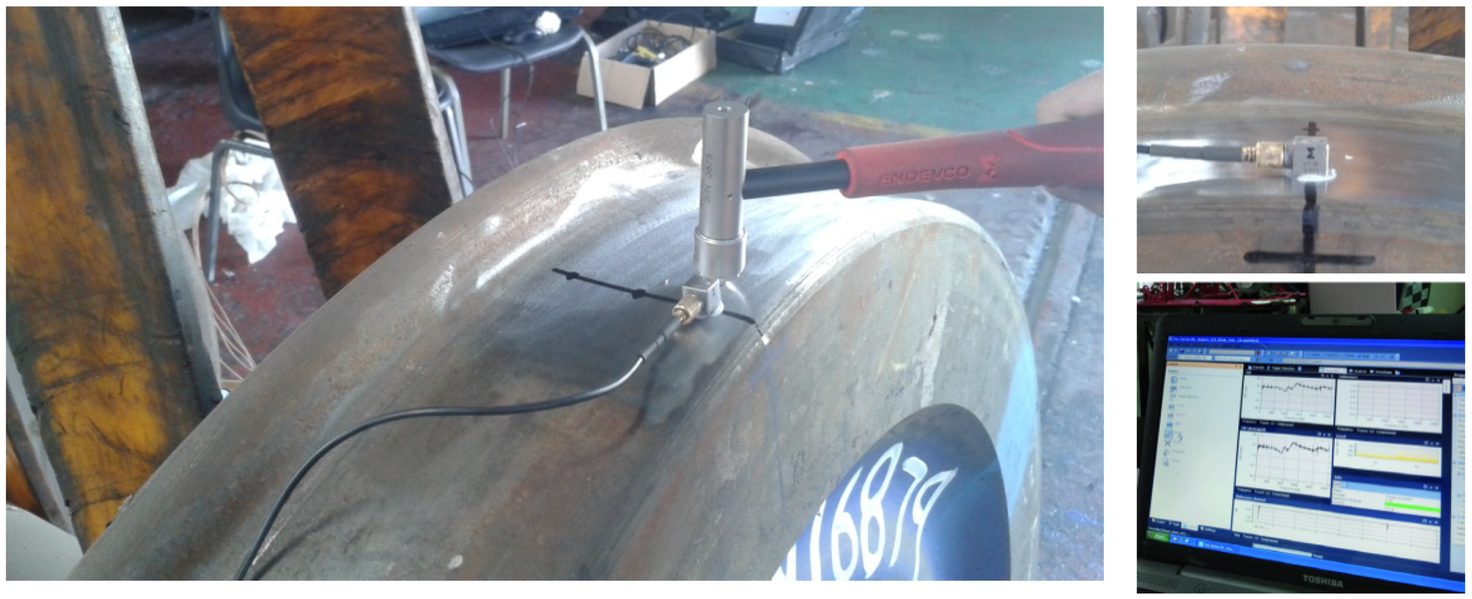
The dynamic characterization of the D39 200 locomotive wheel and the design of the viscoelastic layers to damp wheel vibrations were performed by means of numerical analysis validated through experimental modal analysis (EMA). EMA was carried out by a roving hammer impact test with a Brüel & Kjær piezoelectric charge hammer (Brüel & Kjær, Nærum, Denmark) and a small-sized charge accelerometer (
Figure 4). Frontend data and the specific software Test Xpress Version 10.0 and TestLab Version 16 from Siemens/LMS (Plano, TX, USA) were used for the acquisition of signals, post-processing, FRF calculations and complete identification of the main modes [
34].
Here, the results of the EMA allowed us to fine-tune and validate a nonlinear finite element (FE) model of the wheel with energy absorption capabilities. Harmonic response analyses with the FE model of the wheel were performed through radial and lateral excitations, with the wheel assumed to be rigidly mounted on the axle. Viscoelastic damping layers were introduced into the FE model in three different arrangements of the wheel, and an optimization of vibration amplitude reduction was performed.
2.1. Finite Element Modal Analysis
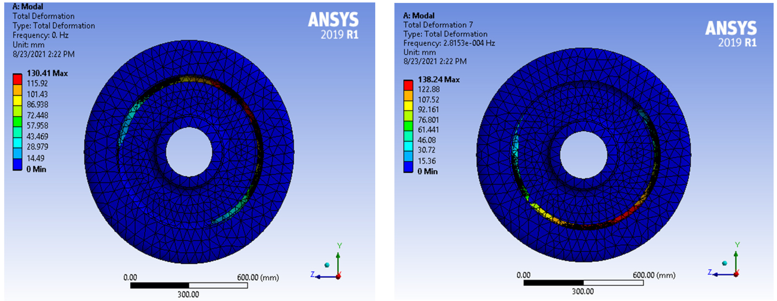
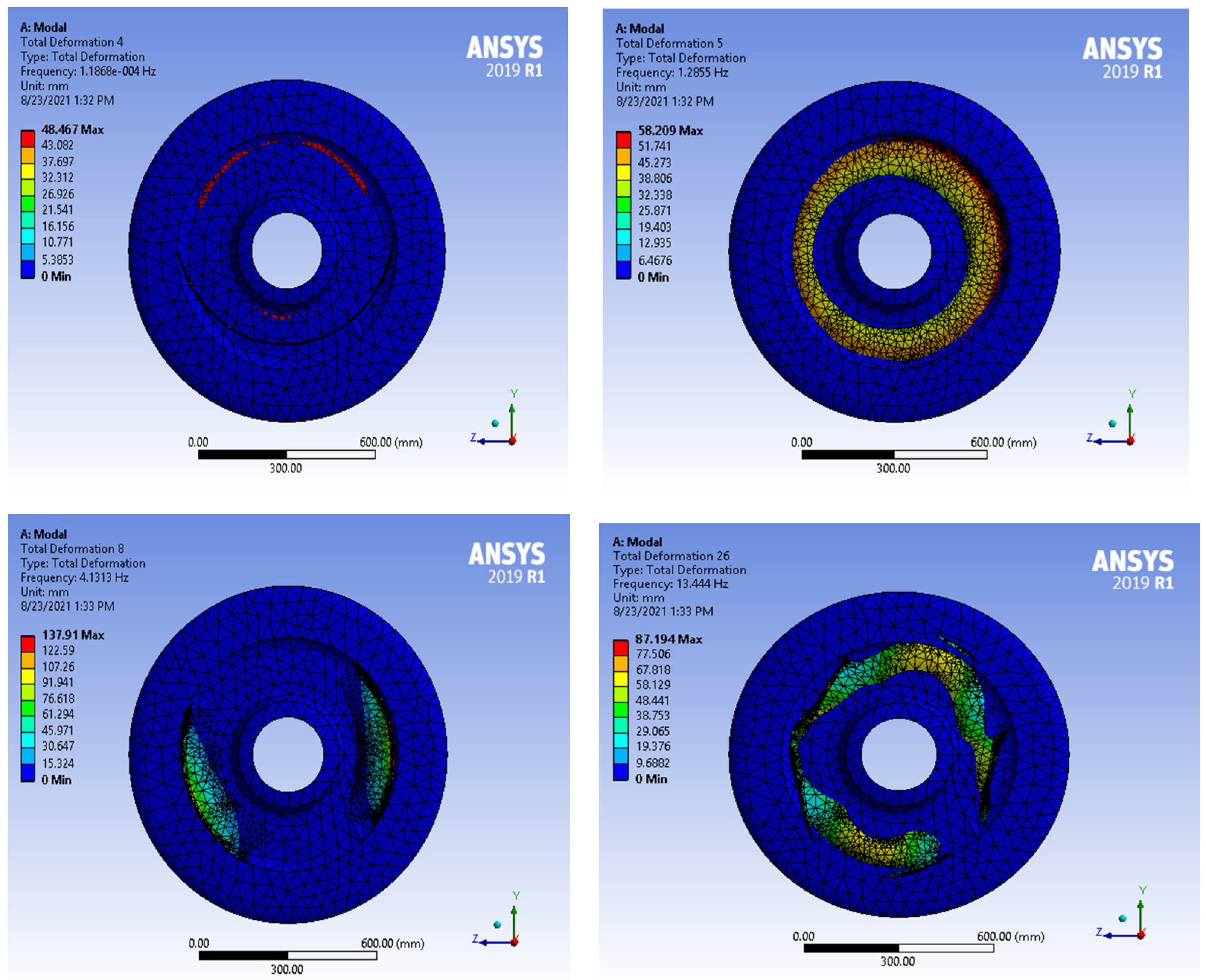
The FE model of the locomotive wheel was meshed using 54,496 nodes and 32,606 tetrahedral 10-node elements (SOLID187) to determine the frequency at which the wheel would experience high-amplitude oscillations that could lead to resonance. The characteristics of the wheel, as well as the finite element modal and harmonic analysis, were performed with ANSYS 2020 R1 (ANSYS Inc., Canonsburg, PA, USA) software (
Figure 5).
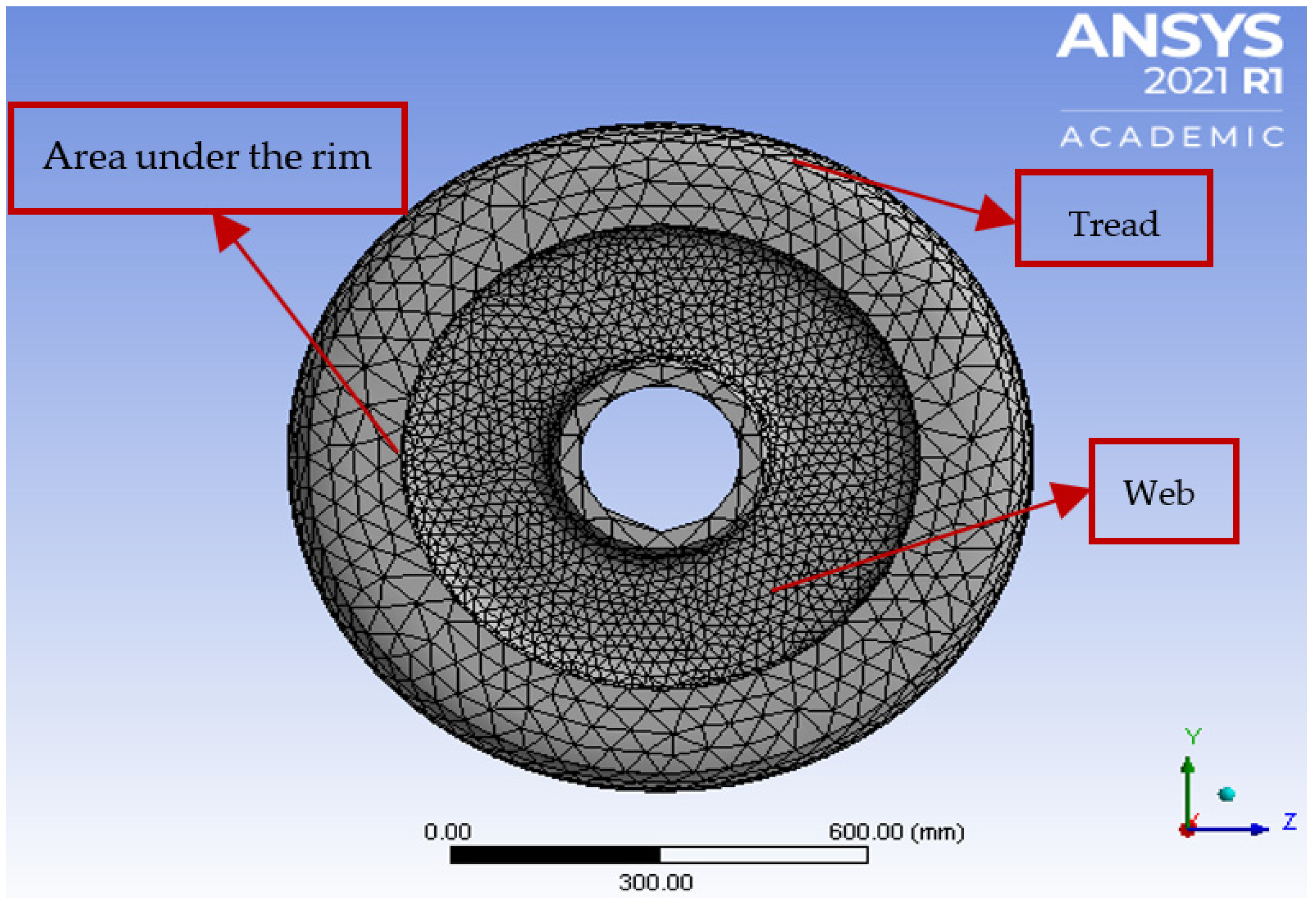
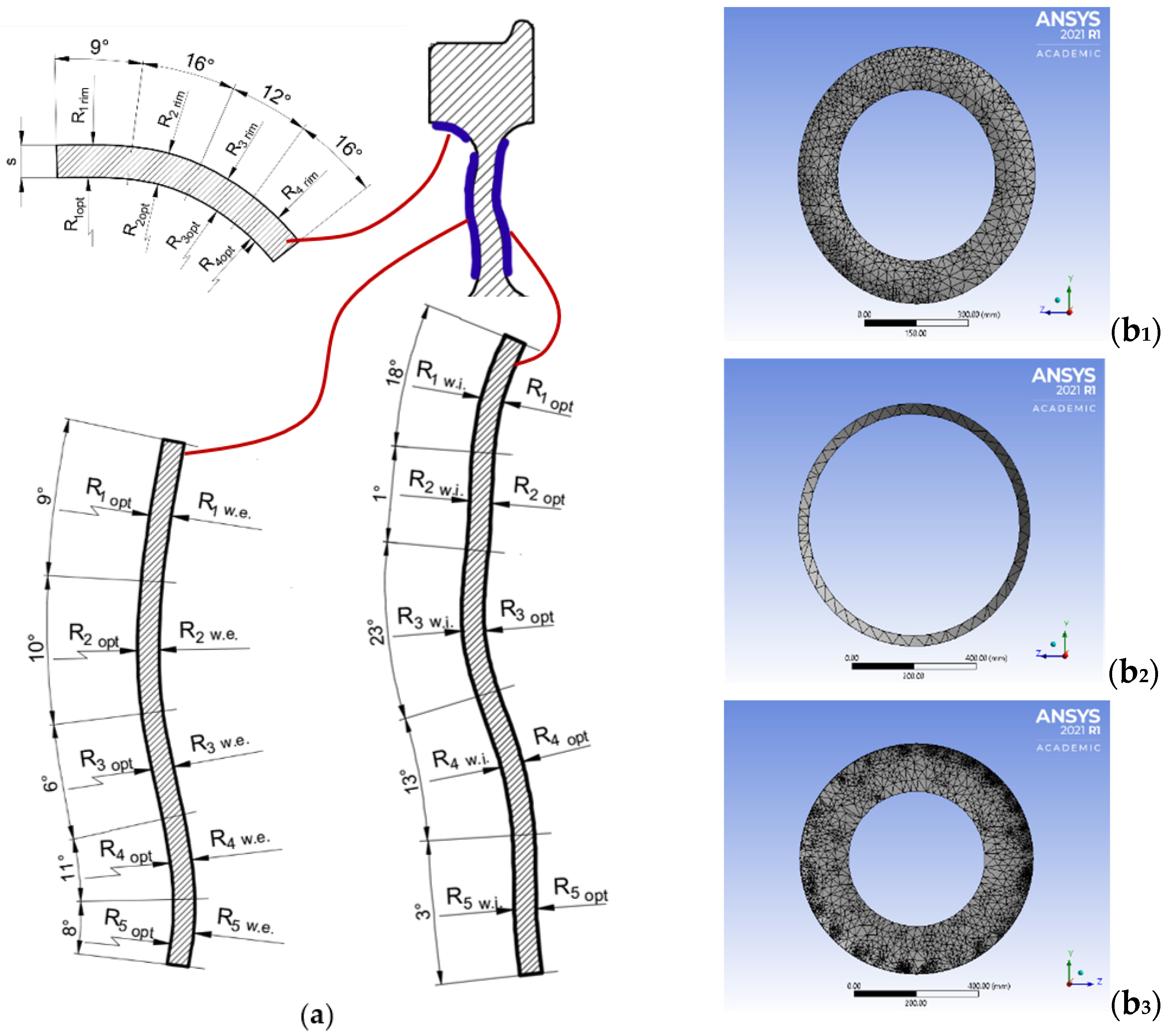
The wheel’s geometric profile, containing curves on the web and under the rim, makes tetrahedron mesh elements particularly suitable to fit the wheel’s geometry [
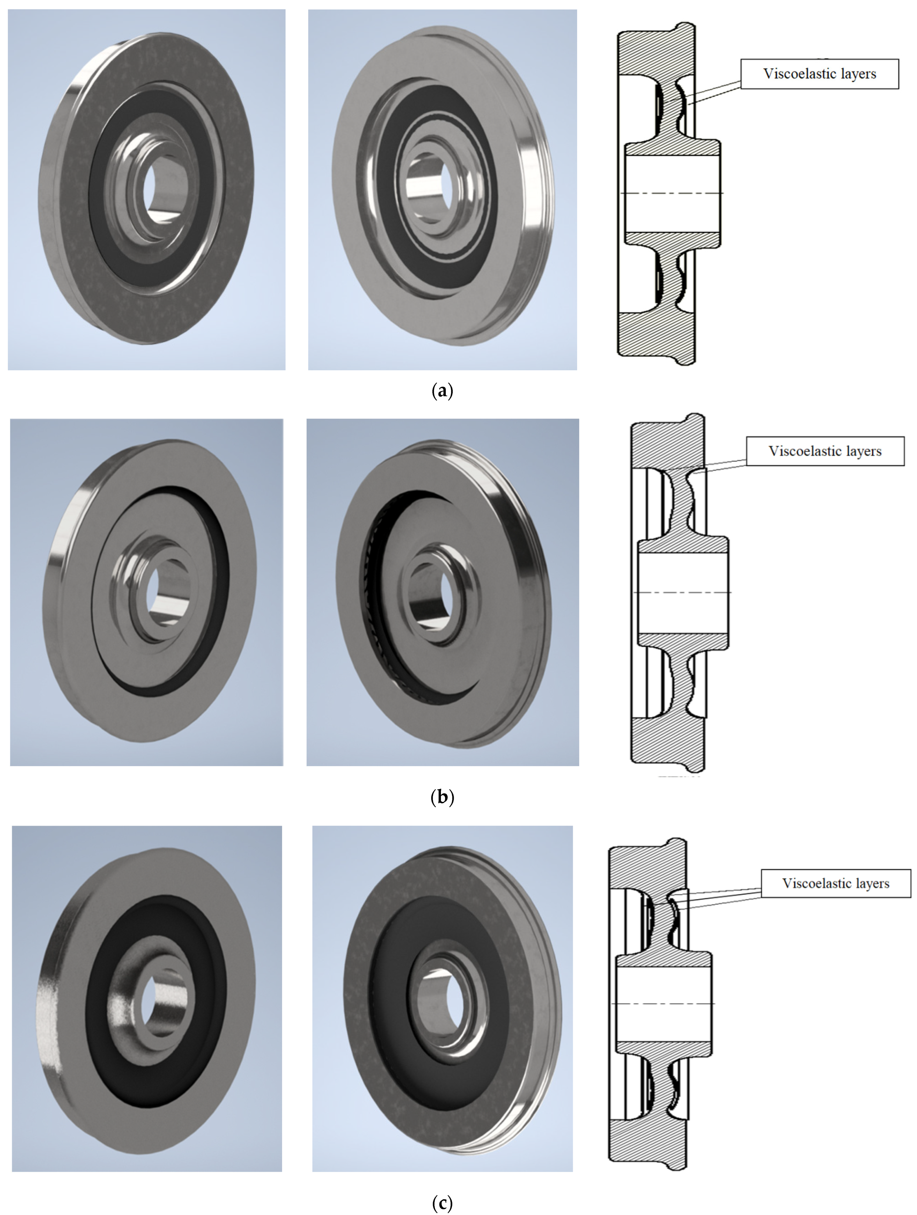
35]. Thus, using Autodesk Inventor code a parametrization of the wheel and damping layer profile was carried out. This process provided the parametric geometric profiles of the cross sections of the three types of layers (on the web of both wheel sides, under the rim of both wheel sides and on the web and under the rim of both wheel sides) used to dampen the vibrations of the wheel (
Figure 6a).
The initial values of the geometric parameters of the layers’ section profiles were obtained by approximating the profiles both under the rim and for the web of both wheel sides with polycentric curves. In particular, four circular arcs were used to approximate the section profile of the under the rim layer, and five circular arcs were used to approximate the section profile on the web of both wheel sides with an accuracy of over 99%. The values of the radii of these arcs constituted the design variables for optimization (
Figure 6a).
After the mesh refinement procedure, which allowed us to validate the FE model based on the EMA, the best geometry of the layers and their best arrangement, which gave the optimal results in terms of vibration damping in the frequency range studied, were calculated. The design values, the optimal values assigned to the radii (design variables) in the parametric optimization study carried out, are shown in
Table 1. The optimal values adopted for the radii of the profiles are the best compromise between the maximum allowed values (
Table 1) and the space requirements of the wheel. They provided optimal thickness values of 8 mm and 10 mm for the viscoelastic damping layer under the rim and the viscoelastic damping layer, respectively.
Figure 6b shows the mesh of the three optimal viscoelastic layer arrangements. The internal web viscoelastic damping layer was meshed using 14,710 nodes and 4459 tetrahedron elements (
Figure 6b
1). The viscoelastic damping layer under the rim was meshed using 7025 nodes and 2778 tetrahedron elements (
Figure 6b
2). The external web viscoelastic damping layer was meshed using 12,025 nodes and 3781 tetrahedron elements (
Figure 6b
3). The mesh size for all three configurations of viscoelastic damping layers was 2 mm.
The mesh refinement procedure was performed by setting 5% as the maximum admissible limit of frequency variation with respect to the values calculated through EMA. Mesh convergence was measured on the sixth deformation mode only for all mesh sizes. Mesh convergence is a good tool to verify if the mesh results are adequate, since the accuracy of a simulation depends on the geometry accuracy, material properties and loads and boundary conditions.
Evident from
Table 2 is that the results did not change with continued mesh refinement. Hence, it can be deduced that convergence was reached using 54,496 nodes and 32,606 tetrahedral elements.
Table 3 shows the material properties adopted in the FE analysis.
2.2. Harmonic Response Analysis
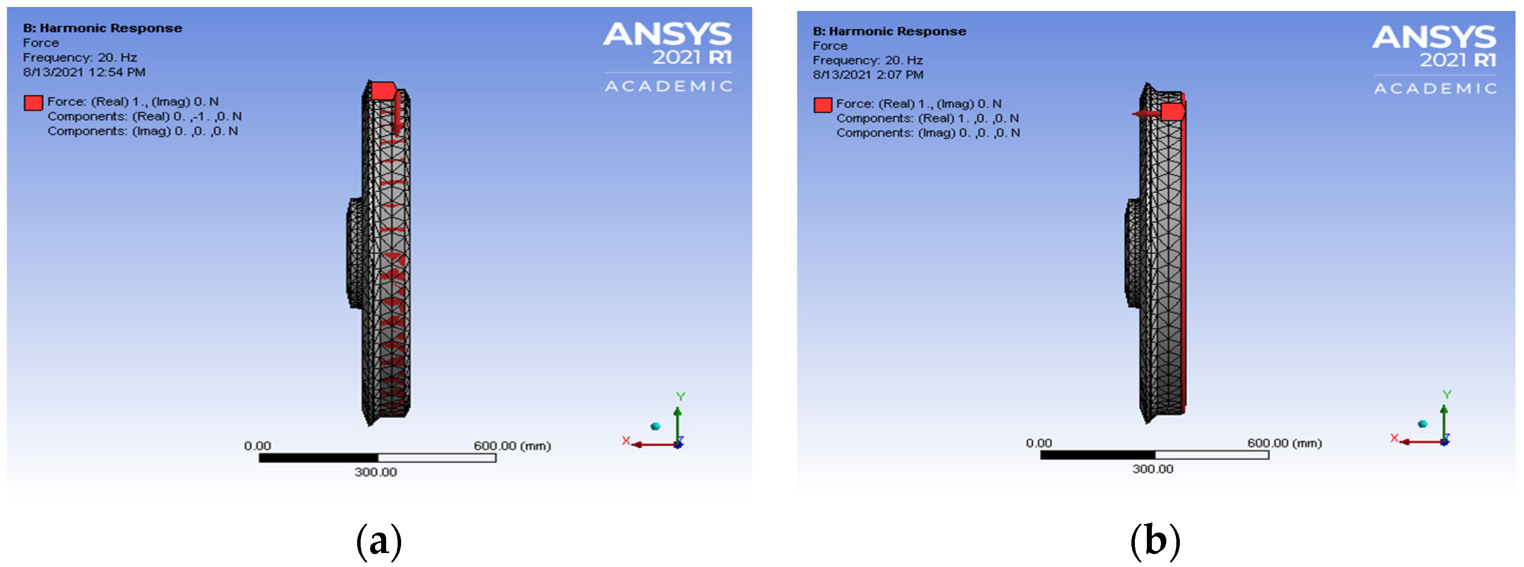
Harmonic Response Analysis (HRA) was conducted from 20 Hz to 5 kHz at 20-Hz intervals. The wheel was set free radially (
y-axis) and laterally (
x-axis). Two directions of the wheel, radial (vertically), and lateral (axially), were excited by a unitary force to investigate the frequency which would experience maximum amplitudes, leading to resonance of the locomotive wheel [
36].
Figure 6a shows the wheel model with the load being applied radially (
Figure 7a). Hence, the impact would represent the vertical harmonic wheel–rail force at the wheel–rail contact point.
Figure 7b shows the load being applied laterally on the wheel model instead. The lateral impact represents the axial harmonic wheel–rail instability that results when the wheel travels through sharp curves while the wheel is experiencing lateral creepage impacts.
2.3. Viscoelastic Damping Layers
Viscoelastic materials have very effective characteristics for controlling vibrations in structural systems. The use of a viscoelastic damping layer depends on the material properties [
37,
38]. The viscoelastic material considered in this research was 3M ISD112 from the 3M™ Viscoelastic Damping Polymers manufacturing company (Tokyo, Japan) because of its widespread use and its commercial availability [
31,
32,
33]. However, the procedure utilized in the scientific literature can obviously be applied to any viscoelastic material. The properties of the viscoelastic material studied in this paper were approximated by the elastic properties listed in
Table 4, and viscous damping would be added additionally by Rayleigh beta damping. ANSYS was adopted to investigate the harmonic response of the wheel, with a viscoelastic damping layer mounted in the three different arrangements shown in
Figure 6a–c.
It was assumed that the viscoelastic damping material only underwent small deformations and hence had linear behavior. The element type used to characterize the viscoelastic damping layer material was the same used in the wheel model in order to ensure good boundary definition. It was proven by Pascon et al. [
39] that the use of tetrahedral elements to solve problems with high polymetric layer materials using Finite Element Analysis does not present locking nor results making the layer too stiff, even if the material layer is applied with other different materials inside the analyzed domain.
For the viscoelastic layers in three optimal configurations, FEMA and HRA of the wheel were performed, and the natural frequencies for the three different positions (
Figure 8a–c) were calculated.
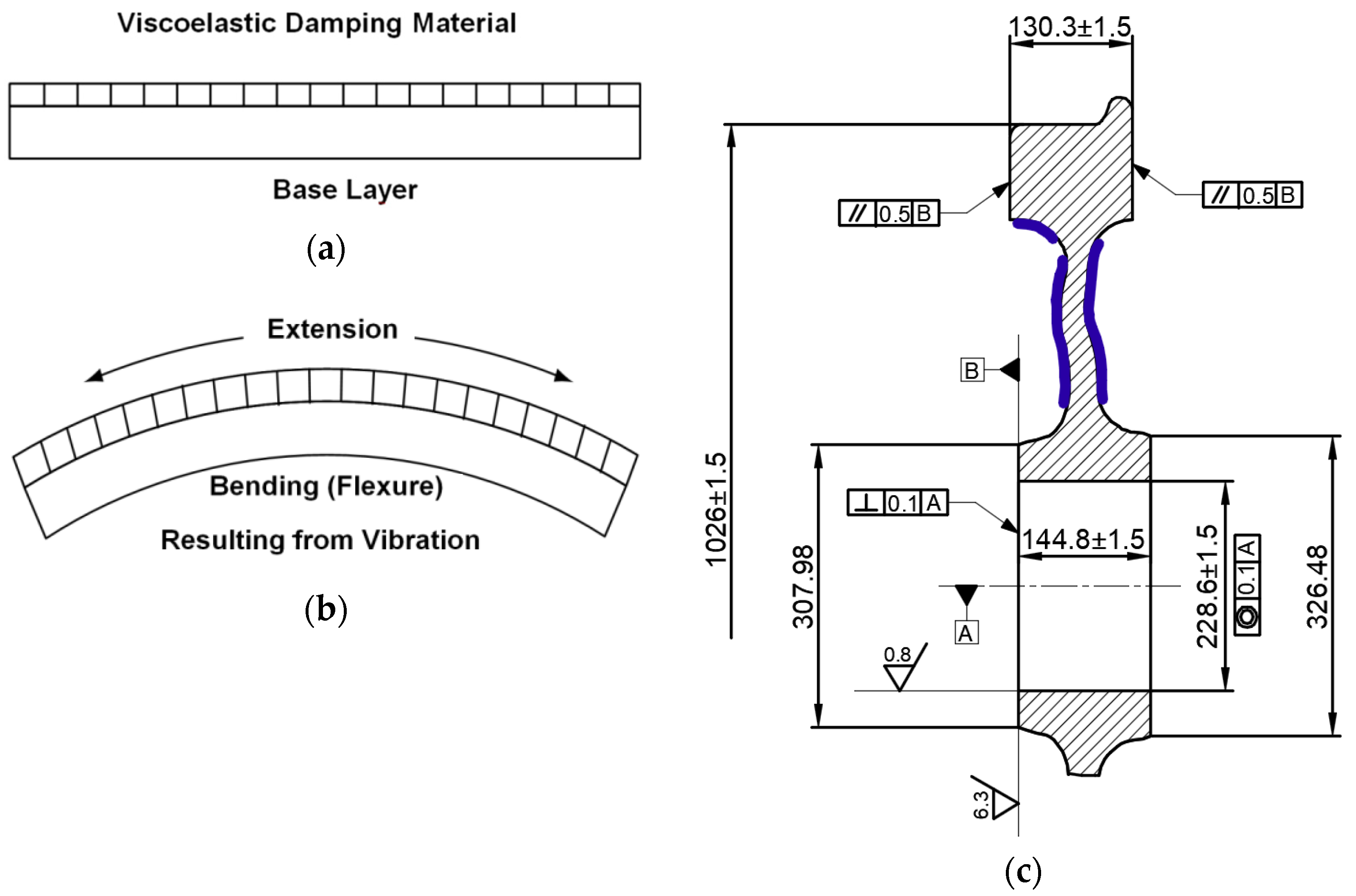
The viscoelastic damping layer was mounted with a strong bonding agent to be in contact with the vibrating structural surface (
Figure 9c). During the vibration of a structure, the viscoelastic damping layer material dissipates vibrations by means of alternate extension and compression of the viscoelastic damping layer as demonstrated in
Figure 9a,b.
The mesh convergence was conducted by decreasing the element size for the viscoelastic damping layers of the web and under the rim. The viscoelastic damping layers on the web and under the rim were chosen to track the convergence since they consisted of both web and under the rim damping components.
Table 5 shows the details of the convergence results of the viscoelastic damping layer.
Figure 9c and
Table 6 show the final optimized model of the wheel for a class D39 200 locomotive and its design dimensions, respectively.
2.4. Harmonic Excitation of a Wheel with Viscoelastic Damping Layers
Finally, the boundary conditions of the wheel were set free radially (y-axis) and laterally (x-axis). Two directions of the wheel, radial and lateral, were excited by unitary force.
4. Discussion
In this section, some critical observations are presented to comprehensively understand the outputted results that were explored under the circumstances described above.
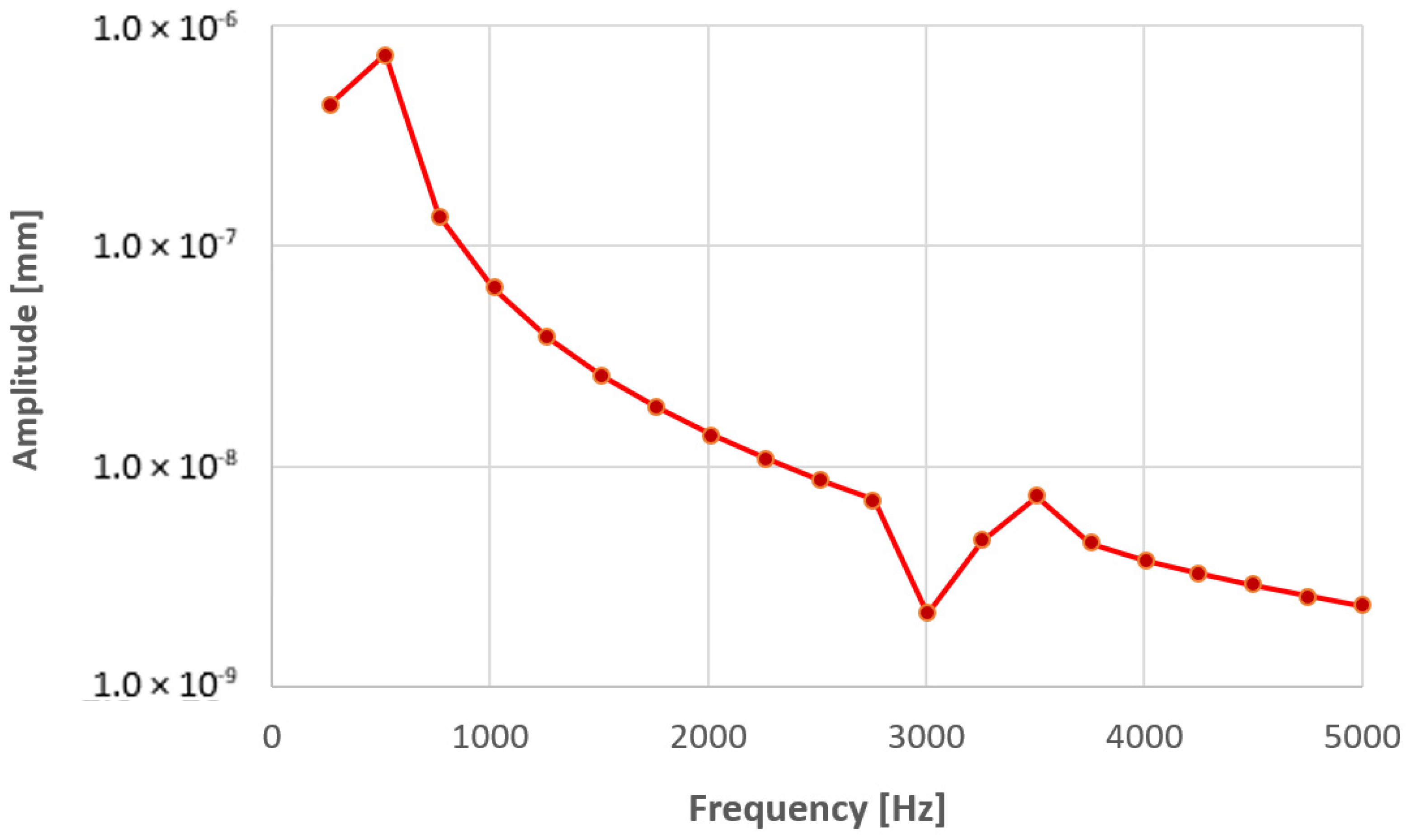
The results from
Figure 12 and
Figure 17 show that the wheel experienced high amplitudes both from radial and lateral excitations. Hence, the frequency value, which was found to have a high amplitude peak on the wheel during excitation, was investigated as indicated in
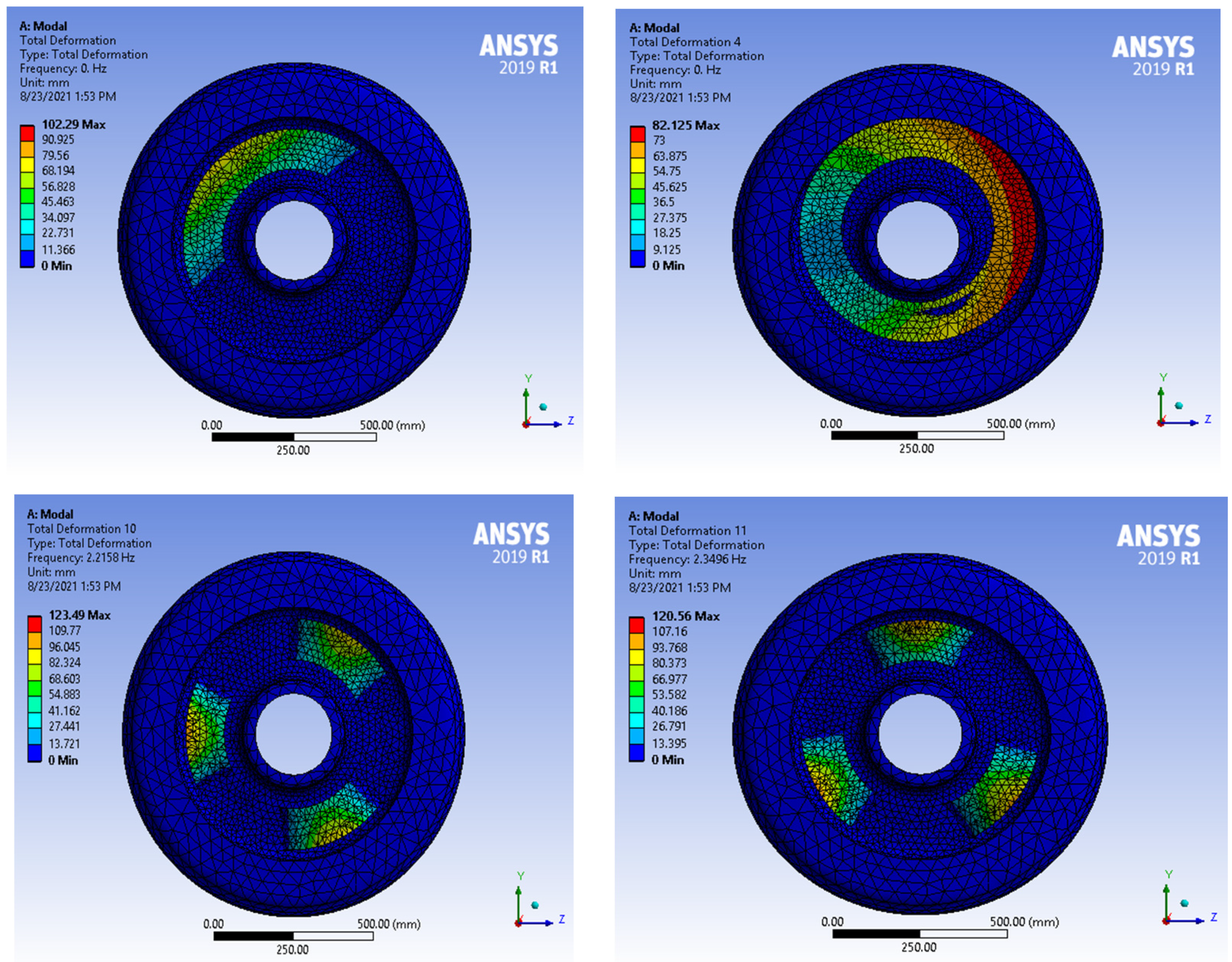
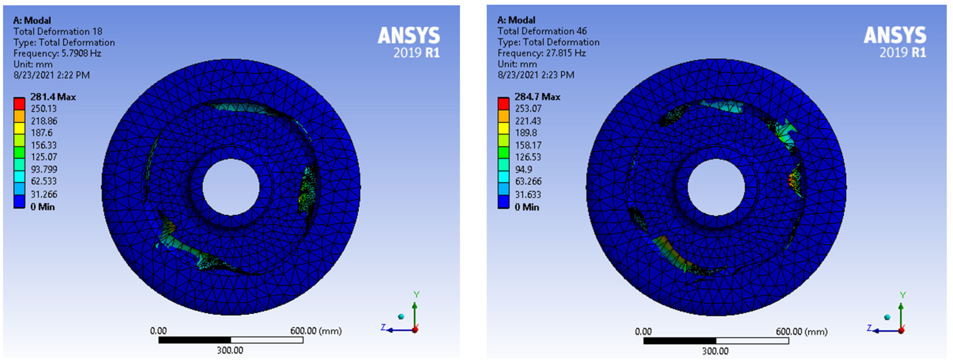
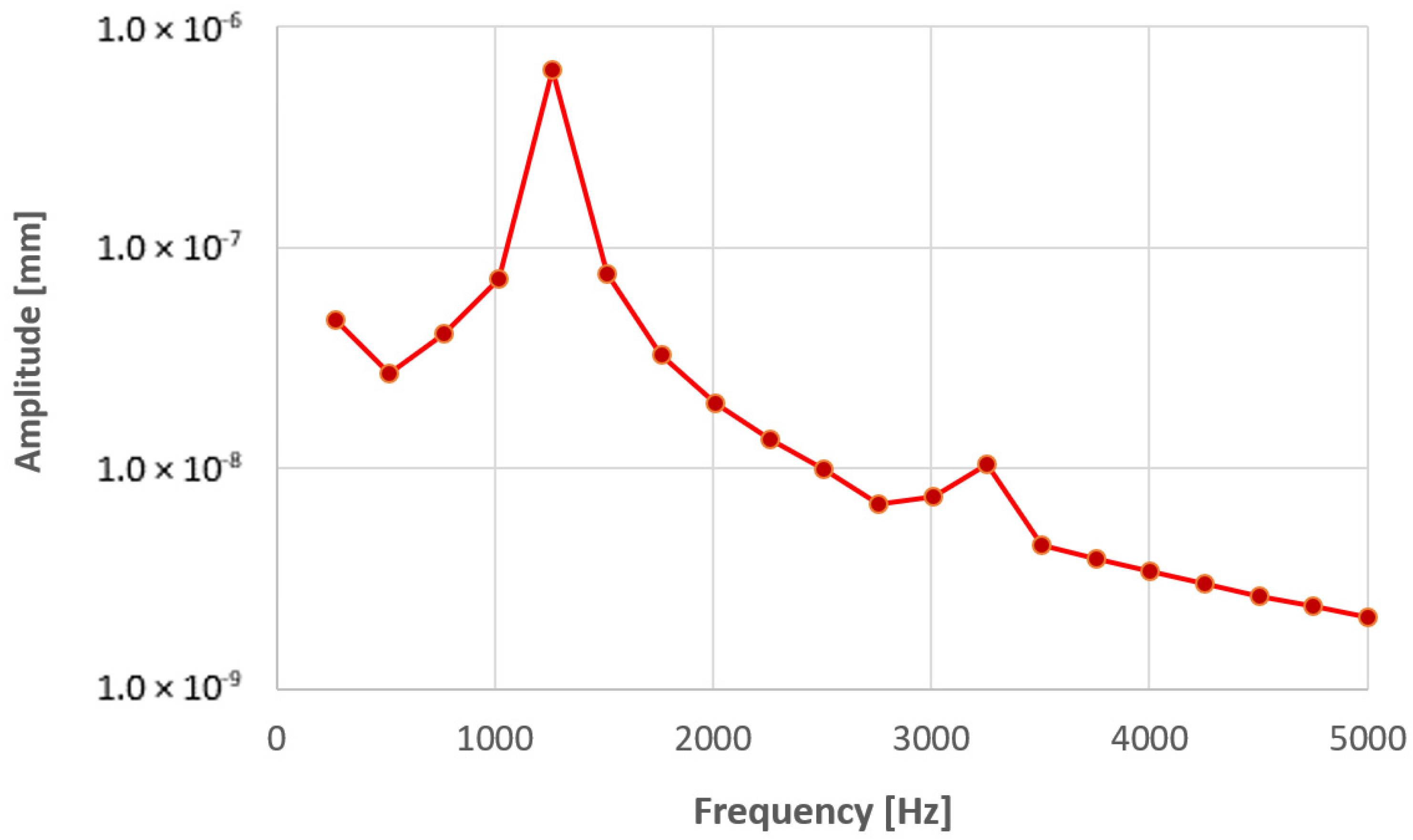
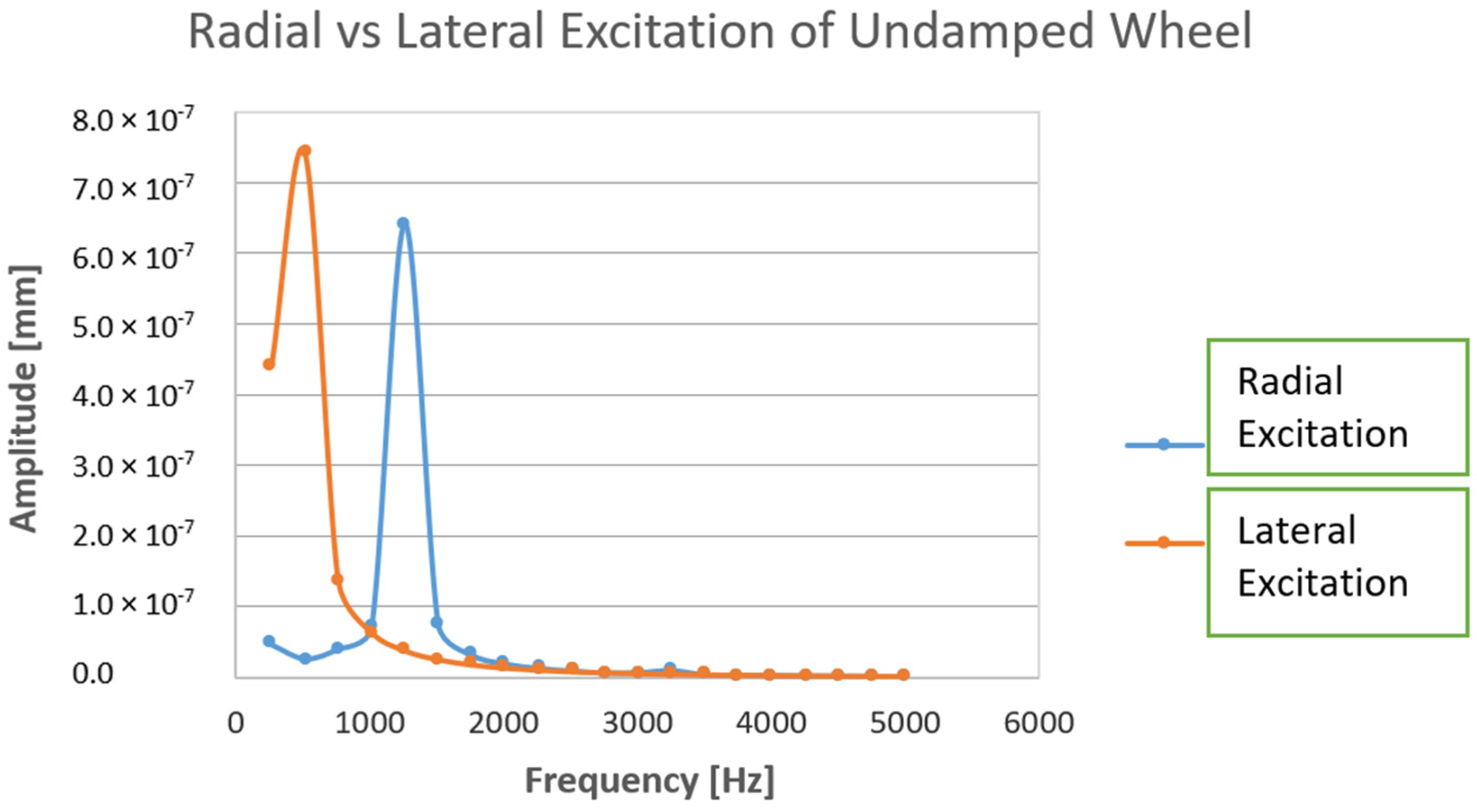
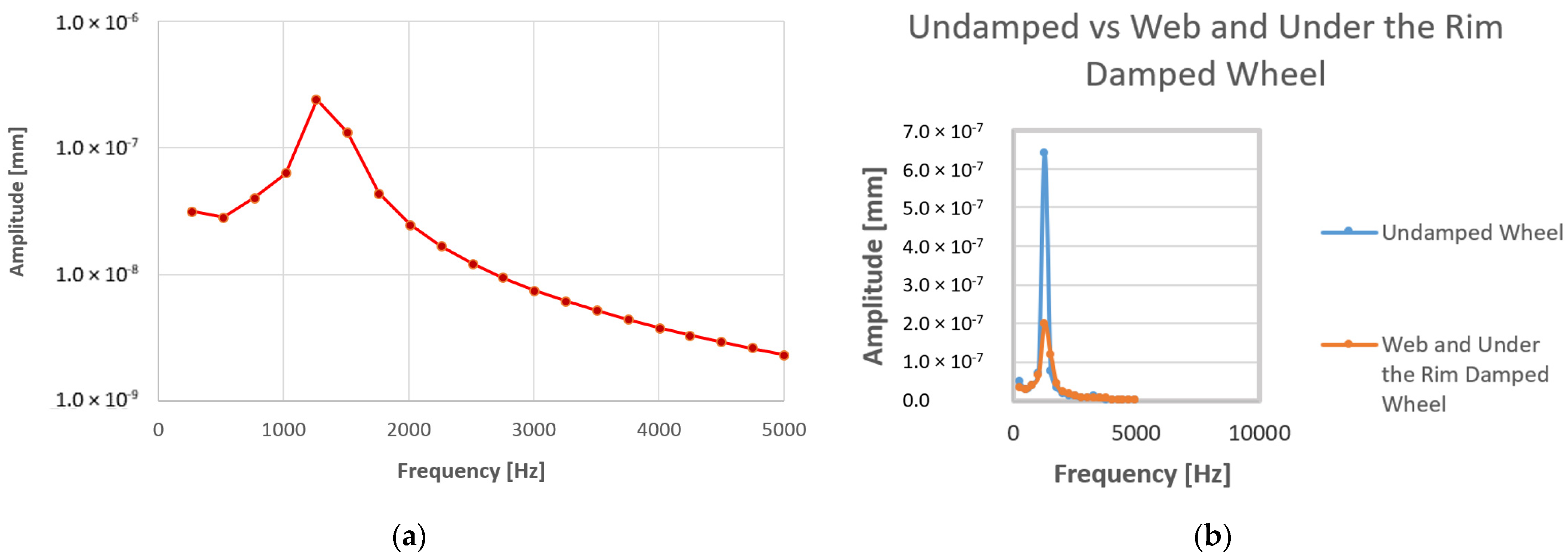
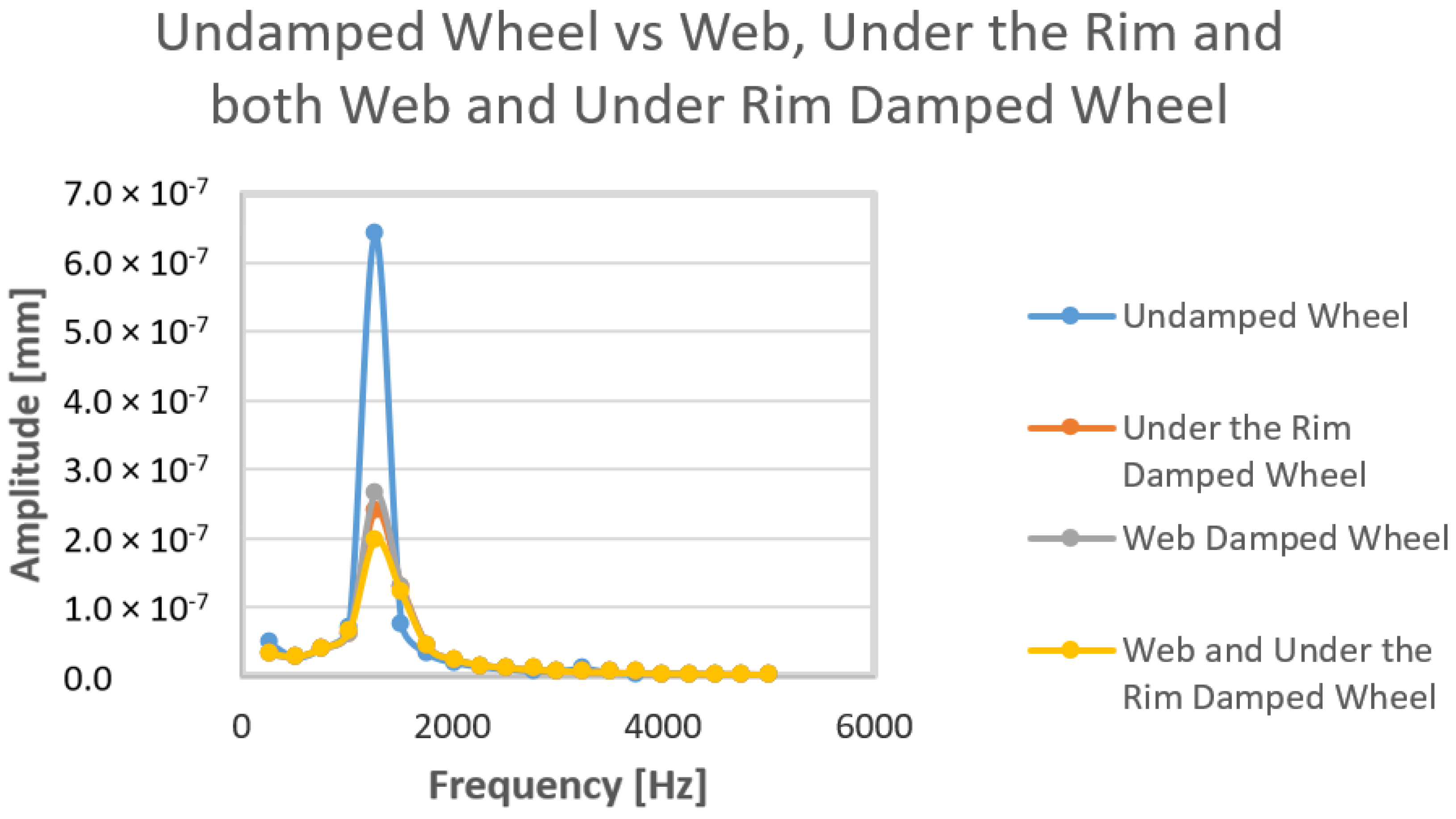
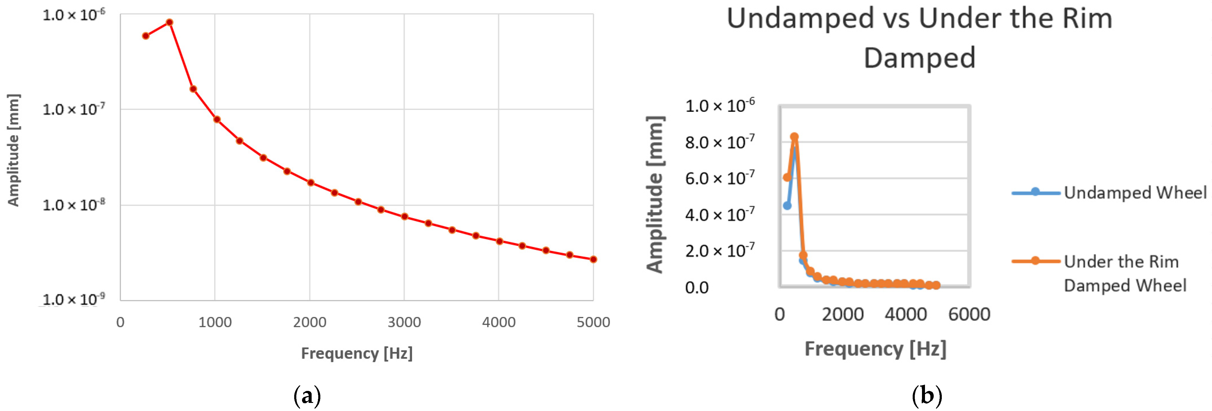
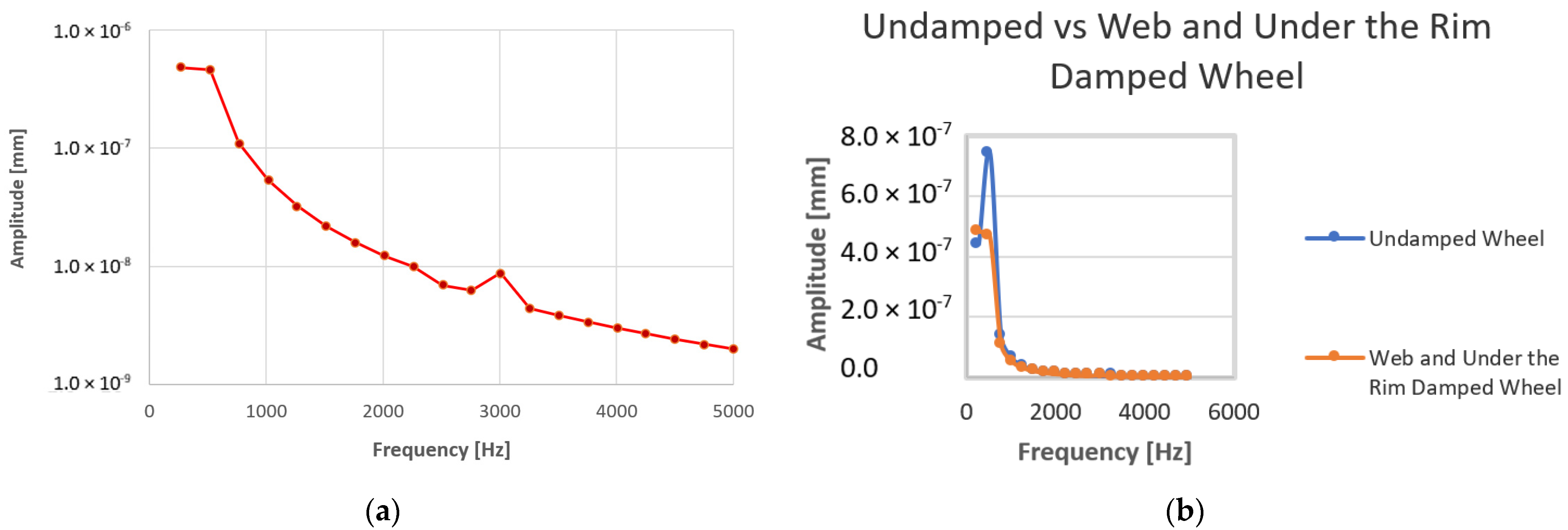
Table 7, which tabulates the natural frequencies and modal vibration numbers. It was found that the wheel resonance corresponded with the wheel mode vibration number 6 for lateral harmonic response and mode vibration number 10 for radial harmonic response. Based on these results, it can be concluded that the wheel would experience resonances at a frequency of 1265 Hz during radial excitation and 518 Hz during lateral excitation, because the harmonic responses of the wheel frequencies at resonance were equal to the natural frequencies of the wheel at mode vibration numbers 6 and 10, respectively.
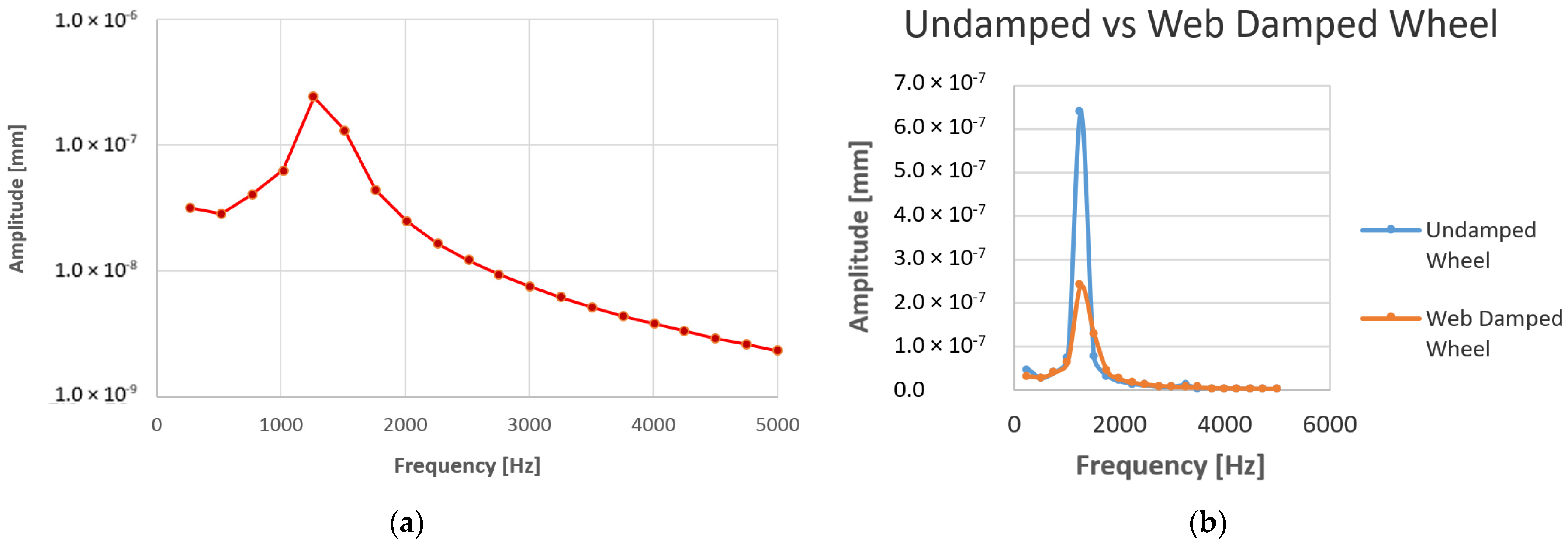
After the viscoelastic damping layer was mounted in three different configurations on the wheel during radial excitation, the evidence from
Figure 17 demonstrates that the viscoelastic damping layer, when mounted on the web and under the rim on both sides of the wheel, exhibited a better damping efficiency than the other cases. After the viscoelastic damping layer was mounted on the web and under the rim on both sides of the wheel, the maximum amplitude was found to be reduced by 442.02 × 10
−9 mm. In the second configuration investigated, when the viscoelastic layer was mounted on the web on both sides of the wheel, the maximum amplitude peak at the resonance frequency was reduced by 400.7 × 10
−9 mm. The final case investigated when the viscoelastic layer was mounted under the rim on both sides of the wheel, and it showed that the maximum amplitude peak at the resonance frequency was reduced by 375.84 × 10
−9 mm. Furthermore, when the damping viscoelastic layer was mounted in three different cases on the wheel during lateral excitation, the evidence from
Figure 21 demonstrates that the viscoelastic damping layer, when mounted on the web and under the rim on both sides of the wheel, exhibited a better damping efficiency than the other cases, because the undamped wheel’s maximum amplitude peak was found to be reduced from 741.669 × 10
−9 mm to 465.14 × 10
−9 mm. That means that the layer was able to reduce the amplitudes by 737.02 × 10
−5 mm from the vibrating peak value. In the second case (under lateral excitation), when the viscoelastic damping layer was mounted on the wheel web on both sides of the wheel, the maximum amplitude peak at the resonance frequency was reduced from 741.669 × 10
−9 mm to 741.64 × 10
−9 mm, indicating that the layer was able to reduce the amplitudes by 290 × 10
−13 mm from the vibration peak value. In the last case (under lateral excitation), when the viscoelastic damping layer was mounted under the rim on both sides of the wheel, the maximum amplitude peak was not reduced, since it was found to increase from 741.669 × 10
−9 mm to 817.33 × 10
−9 mm. These findings have good agreement with the findings from Rizwan et al. [
7], as they concluded that at certain points during excitation, the damping layer could not be effective on the structure. However, the technique shows good efficiency for suppressing both the radial (vertically) and lateral (horizontally) dynamics of the wheel, except during lateral excitation, when the viscoelastic layer was mounted on the web and under the rim.
Cervello et al. [
16] used the same design procedure proposed in this paper to analyze and design a low-noise railway wheel but adopted a constrained damping layer treatment. Jones and Thompson [
39] used a combination of finite element complex modal analysis and TWINS software Version 1.1 to calculate the mode shapes and modal masses of the wheel. The constrained damping layer was designed to mount the wheel with different configurations. It is clear that much work was performed to suppress rail wheel vibration using a constrained damping layer. In the present paper, a viscoelastic damping layer (unconstrained damping layer) was selected to reduce excessive vibrations on the locomotive wheel set.
It is clear from
Table 7 that the mode shapes of the wheel’s natural frequency during both radial and lateral excitations had an extensive impact on the wheel deformation. The displacement of the wheel depended upon the change of direction and modal shape of the wheel.
It is clear from
Figure 9b and
Appendix A,
Appendix B,
Appendix C that the nodes of the wheel mounted with a viscoelastic layer on the web, under the rim and both on the web and under the rim were situated around the light blue color in the code legend. That correlated with the least displacement of the deformed shape and was dominating with respect to the average (yellow and green) and large (red) displacement. The only deformation taking place was on the viscoelastic damping layer, and it can be assumed that this occurred during flexure of the wheel, causing the viscoelastic damping layer to dissipate vibrations by means of compression and tension.


