Article

Influence of System and Actuator Nonlinearities on the Dynamics of Ring-Type MEMS Gyroscopes

by
Ibrahim F. Gebrel
1,2 and
Samuel F. Asokanthan
1,*
1
Department of Mechanical and Materials Engineering, The University of Western Ontario, London, ON N6A 5B9, Canada
2
Department of Mechanical Engineering, Azzaytuna University, Tarhuna P.O. Box 5338, Libya
*
Author to whom correspondence should be addressed.
Vibration 2021, 4(4), 805-821; https://doi.org/10.3390/vibration4040045
Submission received: 31 August 2021 / Revised: 12 October 2021 / Accepted: 19 October 2021 / Published: 25 October 2021

Abstract

:
This study investigates the nonlinear dynamic response behavior of a rotating ring that forms an essential element of MEMS (Micro Electro Mechanical Systems) ring-based vibratory gyroscopes that utilize oscillatory nonlinear electrostatic forces. For this purpose, the dynamic behavior due to nonlinear system characteristics and nonlinear external forces was studied in detail. The partial differential equations that represent the ring dynamics are reduced to coupled nonlinear ordinary differential equations by suitable addition of nonlinear mode functions and application of Galerkin’s procedure. Understanding the effects of nonlinear actuator dynamics is essential for characterizing the dynamic behavior of such devices. For this purpose, a suitable theoretical model to generate a nonlinear electrostatic force acting on the MEMS ring structure is formulated. Nonlinear dynamic responses in the driving and sensing directions are examined via time response, phase diagram, and Poincare’s map when the input angular motion and nonlinear electrostatic force are considered simultaneously. The analysis is envisaged to aid ongoing research associated with the fabrication of this type of device and provide design improvements in MEMS ring-based gyroscopes.

1. Introduction

Vibratory angular rate sensors have received considerable attention in the recent past, primarily due to the economic and technological advantages offered by this class of sensors. This class of devices works on the principle of Coriolis acceleration and the vibratory behavior of specific structural systems such as mass-springs, beams, and rings. There are many sources of nonlinearities in MEMS owing to the force, damping, and stiffness. The present study focuses on a nonlinear system and the interaction of nonlinear electrostatic forces to investigate the nonlinear dynamic response behavior. The introduction of nonlinear mode functions to effectively handle these nonlinearities in the MEMS ring-based structure opens a new research area. Investigations into the performance of such a new study, namely a nonlinear ring gyroscope with nonlinear electrostatic force, have been demonstrated via numerical simulations. One of the most critical challenges in constructing ring-based vibratory gyroscopes is the need for this class of devices to operate at one of the ring resonant frequencies to increase the device sensitivity. However, large resonant amplitudes tend to suffer from undesirable nonlinear effects owing to geometric and actuator nonlinearities. Hence, nonlinear dynamic analysis of ring structures and consideration of input nonlinear actuator dynamics are warranted to gain a complete understanding of achievable performance improvements that can be offered for this class of rate sensors.
Several studies on the nonlinear and linear dynamic behavior of rotating rings have been undertaken recently. Thin circular ring-type structures have gained much acceptance due to inherent advantages such as minimal drift to temperature fluctuation, high sensitivity to rotation, and less sensitivity to environmental vibrations, particularly for MEMS applications Putty and Najafi [1]. Evensen [2,3] performed early studies on the nonlinear vibration of rings considering only the in-plane vibrations of a thin circular ring and derived nonlinear equations of motion. Later, detailed studies on nonlinear flexural vibrations of rings considered two vibration modes and employed Galerkin’s method. The in-plane vibration behavior of rotating rings and the effect of rotation and elastic foundation on the natural frequencies and mode shapes have been investigated by Sodel [4] and Huang and Sodel [5]. Coriolis forces induced in the ring gyro during the rotation of the ring cause the excited ring to shift vibration into the next resonance mode (Eley et al. [6]). Bickford and Reddy [7] investigated the effects of extensional and shear deformations and inertia on natural frequency variations. The natural frequency splitting and mode contamination of the rotation ring-shaped periodic structures were analytically examined by Zhang et al. [8]. Asokanthan and Cho [9] and Cho [10] developed mathematical models for rotating ring-based angular rate sensors to investigate the linear and nonlinear dynamic behavior and dynamic stability of angular rate sensors subjected to external excitation. However, the linearized equations of motion were derived by ignoring the nonlinear terms, which were then used to investigate the stability behavior. Recently, the dynamic stability behavior of ring-based gyroscopes under external stochastic angular rate fluctuations employing a stochastic differential equation formulation together with higher-order numerical schemes have been studied by Asokanthan et al. [11]. It should be noted that this study was also based on a linear model. The dynamic response behavior of rotating thin circular rings for use in vibratory angular rate sensors was investigated by Gebrel et al. [12] via numerical simulations by employing a linearized model considering the second mode. In the same study, they developed a suitable theoretical model to generate nonlinear electromagnetic forces used to excite the ring from two positions to obtain improved device sensitivity. Gebrel et al. [13] investigated the nonlinear dynamic response of a rotating ring that forms an essential element in macro ring-based vibratory gyroscopes that utilize oscillatory nonlinear electromagnetic forces. This study examined the nonlinear dynamic response in the driving and sensing directions via time response, phase diagram, and Poincare’s map when the input angular motion and the nonlinear electromagnetic forces are considered to act simultaneously. It is concluded that the device exhibits high nonlinearity in the nonlinear term in the model, which may be attributed to the high vibration amplitudes. In another study, the dynamic behavior of rotating MEMS-based vibratory gyroscopes via numerical simulations by considering a linearized model subjected to a nonlinear actuator was performed by Gebrel et al. [14]. Yoon et al. [15] presented a detailed model for describing the possible vibration effects on MEMS degenerate gyroscopes. A novel low-cost piezoelectric ring vibrating gyroscope based on the side-driving piezo electrodes was designed, simulated, and characterized by Zhou et al. [16]. In their study, the piezoelectric ring vibratory gyroscope was actuated and sensed by piezo electrodes located on the sidewalls of the resonating structure. The nonlinear structural behavior of a size-dependent MEMS gyroscope assuming a non-trivial-shaped proof mass was studied by Hassen [17]. A novel compound fast fractional integral sliding mode control and adaptive PI control of a MEMS gyroscope was proposed by Rahmani and Rahman [18] to represent external disturbances. Napoli et al. [19] investigated frequency splitting in a MEMS ring-based Coriolis vibrating gyroscope caused by support nonlinearity. A recent study investigated a cylindrical fused silica resonator’s dynamic response and frequency split behavior via simulations and experiments Luo et al. [20]. To this end, a cylindrical resonator with appropriate dimensions was designed and fabricated. A laser Doppler vibrometer was used for the experimental quantification of the physical characteristics of the resonator. In a previous study, they investigated the dynamic stability of cylindrical fused silica resonators subjected to random angular rate perturbation (Luo et al. [21]). Their study was concerned with an experimentally fabricated resonator that resembles the dimensions of resonators used in commercially available gyroscopes. In this study, the results indicate a suitable drive frequency scheme for increased resonator stability. In addition, based on model-based predictions, the effect of environmental noise on the dynamic behavior of the resonator was examined. In addition, Luo et al. [20] and Luo et al. [21] focused on utilizing the model-based predictions of response as well as stability in modifying the manufacturing processes. In this case, a chemical etching process was implemented to minimize the adverse effects of the frequency-split behavior. Saghir and Younis [22] investigated the mechanical behavior of initially curved microplates under electrostatic actuation. They derived a dynamic analogy of the von Kármán governing equation for such plates. Theoretical and experimental studies on the linear and nonlinear dynamics of MEMS/NEMS (Nano Electro Mechanical Systems) and their exploitation for various applications have been investigated in detail [23,24,25]. Further, another important research has been performed on nonlinear microsystems, such as reduced-order modeling and gyroscopes [26,27,28]. The dynamic integrity of various electrostatic MEMS actuators has been developed and utilized in various applications [29,30,31,32,33,34,35]. The study [36] demonstrated experimentally that an actuator could exploit parametric resonators to improve the dynamic response behaviour. Additionally, the electrostatic nonlinearity and the achievable limit sensitivity beyond the linear range have been studied theoretically and experimentally to overcome the mode aliasing limitation in linear mode local sensors [37]. Further, the analytical model that takes into account the edge effect has been used to track the periodic motion of the sensing component in the resonant micro-gyroscope. In the same study, different parameter tests were performed to check the influence of the proof mass frequency on the bifurcation behaviour [38]. Significant research on physical phenomena was investigated for various examples at the MEMS/NEMS scale considering different physical parameters, such as internal resonances [39], bifurcations [40,41], and chaos [42]. Furthermore, Passaro et al. [43] considered mechanical gyroscopes, silicon MEMS gyroscopes, ring laser gyroscopes, and fiber-optic gyroscopes, focusing on the main features, performance, technologies, and applications. Without a thorough understanding of the effects of electrostatic force in MEMS systems, many observed phenomena, such as sensitivity and nonlinearity, would have no scientific explanation. Thus, it is necessary to study the electromechanics of a micron-scale structure using an electrostatic actuator.
To the best of the author’s knowledge, it appears that no study has been performed to understand the dynamic behavior of ring-type MEMS gyroscopes employing a nonlinear coupled model which considers nonlinear electrostatic forces. Hence, there is a need to extend the applications of other responsive structural systems, such as the ring systems proposed in the present study, to design models. However, ring structure gyroscopes are more promising because of their inherent advantages such as high mode sensitivity and minimal sensitivity to temperature fluctuations compared with other structures.
In the present paper, nonlinear and linear dynamic response analysis of a ring-type MEMS gyroscope under the influence of nonlinear electrostatic forces in the presence and absence of nonlinear terms was investigated via numerical simulations. The natural frequency variation and amplitude ratio for the MEMS configuration of the gyroscope were computed. The results are presented in the time and frequency domains when the gyroscope is subjected to an input angular rate. In addition, the phase diagram and Poincare maps were obtained via numerical simulation for linear and nonlinear systems, in particular, to gain insight into the inherent nonlinear behavior.

2. Governing Equations

In this section, a comprehensive mathematical model that represents the nonlinear and linear dynamic behavior of MEMS ring-type vibratory angular rate sensors is derived. In the present model, the transverse shear deformation effect is ignored by the thin-ring assumption. The equations of motion were derived using Hamilton’s principle [9], representing the transverse and circumferential motions of the ring. The effect of the elastic support for the ring is included, and simplified equations of motion are obtained by assuming that the circumferential strain in the mid-surface is zero. The equations of motion are expressed in terms of suitable generalized coordinates by applying Galerkin’s procedure. To adequately represent the dynamic response behavior of a ring-type vibratory angular rate sensor, the nonlinear equations of motion have been simplified by ignoring the extensional vibration because a particular resonant flexural mode is excited in this class of applications. The viscous damping of the MEMS ring gyroscope was added to the final approximated equations of motion.
Figure 1 illustrates the geometry and parameters used in this study. The ring is considered to be supported internally with eight springs with stiffness components k r and   k θ , which represent the radial and circumferential components, respectively, while u r   and u θ represent the transverse and circumferential displacements, respectively. A body-fixed frame   X , Y , Z has been used to define the angular motion of the ring. In addition, b denotes the axial thickness of the ring, h represents the radial thickness, r is the mean radius of the ring, and Ω is input angular rate.
The general equations of motion that govern the transverse and circumferential motions can be derived using Hamilton’s principle. For this purpose, expressions for various energy terms have been developed. The kinetic energy of the rotating ring is generated from the translational and rotational rigid body motion of the ring. The strain energy was formulated from the deformation of the ring. The energy generated from the support springs and loads is included, and only the in-plane flexural vibrations of the ring that are of interest to the device operation are considered. The equation of motion for the system under external oscillatory nonlinear electrostatic force, with the linear in-extensional condition in the radial direction, takes the following form:
E A b r 2 ( u θ + u r ) E I b r 4 ( u θ u r ) + ρ h Ω 2 ( 2 u θ u r ) + k r u r + ρ h ( u ¨ r Ω ˙ u θ 2 Ω u ˙ θ ) = f N e s   ( A n , B n , θ i ) cos ( ω t ) ,
where the time derivatives are indicated by (   ) ˙ , while the spatial derivatives are indicated by (   ) . In Equation (1), E is the Young’s modulus, I denotes the area moment of inertia of the ring cross-section, ρ represents the mass density, E I represents flexural rigidity, and A is the cross-sectional area of the ring. An oscillatory external nonlinear electrostatic force magnitude   f N e s   ( A n , B n , θ i ) and of frequency ω is considered. This force plays an essential role in the device operation to excite the structure at a particular resonant mode. The input angular rate and angular acceleration, respectively, are denoted by Ω and Ω ˙ . The area moment of inertia of the ring cross-section about its neutral axis is expressed as I = b h 3 / 12 . The partial differential Equation (1) is reduced to nonlinear ordinary differential equations by assuming nonlinear mode shapes for the ring second flexural modes via Galerkin’s procedure. Owing to the periodic nature of solutions and the choice of deflection modes, the most general radial and circumferential (extensional) displacements compatible with the continuity requirements can be formulated as follows [2]:
u r = A n cos ( n θ ) + B n sin ( n θ ) n γ 4 r [ A n 2 + B n 2 ]
u θ = 1 n [ A n sin ( n θ ) B n cos ( n θ ) ] + γ 8 r [ A n 2 + B n 2 ] sin ( 2 n θ ) γ 4 r A n B n cos ( 2 n θ )
where A n and B n denote time-dependent generalized coordinates in the primary and secondary directions, respectively, while n denotes the number of modes. The parameter γ = n ( 1 1 n 2 ) 2 represents the measure of system nonlinearity. It should be noted that by setting this parameter to zero, the corresponding linear equations can be obtained. As shown in Equations (2) and (3), this parameter influences the homogenous and non-homogenous parts of Equation (1). Hence, this characteristic that results from the inextensionality of the middle surface is termed system nonlinearity. Evensen [2,3] performed a detailed investigation of the dynamics of this class of structures. Each A n and B n can, in turn, be expanded as a Fourier series in time; thus, it is possible to represent virtually any radial or circumferential deflection of interest in Equations (2) and (3). The functions cos n θ and sin n θ associated with the nonlinear term γ are the nonlinear vibration modes of the ring, and since only flexural motions are considered, Equations (2) and (3), in the present study, are restricted to n = 2 . In order to apply Galerkin’s procedure, Equations (2) and (3) are substituted for u r in Equation (1), and the resulting expression is then multiplied by the weighting function associated with A n and integrated with respect to θ from 0 to 2 π . This procedure yields an ordinary differential equation that primarily A n . When an equation for B n is obtained in a similar fashion, both equations are coupled in nonlinear terms. The derivatives of the u r and u θ with respect to the t and θ were used, and the final derivatives were obtained as follows:
u r = n 4 A n cos ( n θ ) + n 4 B n sin ( n θ )
u ¨ r = A ¨ n cos ( n θ ) + B ¨ n sin ( n θ ) n γ 2 r [ A ˙ n 2 + A n A ¨ n ( t ) + B ˙ n 2 + B n B ¨ n ]
u θ = [ A n cos ( n θ ) + B n sin ( n θ ) ] + n γ 4 r [ A n 2 + B n 2 ] cos ( 2 n θ ) + n γ 2 r A n B n sin ( 2 n θ )
u θ = [ n 2 A n cos ( n θ ) n 2 B n sin ( n θ ) ] n 3 γ r [ A n 2 + B n 2 ] cos ( 2 n θ ) 2 n 3 γ r A n B n sin ( 2 n θ )
The weighting functions used in this procedure are:
u r A n = n γ 2 r A n + cos ( n θ )
and
u r B n = n γ 2 r B n + sin ( n θ ) ,
to obtain the equations motion in the coordinates A n and B n , respectively.
By substituting Equations (2) through (7) in Equation (1) and multiplying the resulting expression by the weighting Functions (8) and (9) associated with A n and B n , respectively, and integrating with respect to θ from 0 to 2 π , the following equations are obtained:
0 2 π { E A b r 2 { [ A n cos ( n θ ) + B n sin ( n θ ) ] + n γ 4 r [ A n 2 + B n 2 ] cos ( 2 n θ ) + n γ 2 r A n B n sin ( 2 n θ ) + A n cos ( n θ ) + B n sin ( n θ ) n γ 4 r [ A n 2 + B n 2 ] } E I b r 4 { [ n 2 A n cos ( n θ ) n 2 B n sin ( n θ ) ] n 3 γ r [ A n 2 + B n 2 ] cos ( 2 n θ ) 2 n 3 γ r A n B n sin ( 2 n θ ) n 4 A n cos ( n θ ) n 4 B n sin ( n θ ) } + ρ h Ω 2 { 2 [ A n cos ( n θ ) + B n sin ( n θ ) ] + n γ 2 r [ A n 2 + B n 2 ] cos ( 2 n θ ) + n γ r A n B n sin ( 2 n θ ) + n 2 A n cos ( n θ ) n 2 B n sin ( n θ ) } + k r { A n cos ( n θ ) + B n sin ( n θ ) n γ 4 r [ A n 2 + B n 2 ] } + ρ h { A ¨ n cos ( n θ ) + B ¨ n sin ( n θ ) n γ 2 r [ A ˙ n 2 + A n A ¨ n + B ˙ n 2 + B n B ¨ n ]   Ω ˙ [ 1 n [ A n sin ( n θ ) B n cos ( n θ ) ] + γ 8 r [ A n 2 + B n 2 ] sin ( 2 n θ ) γ 4 r A n B n cos ( 2 n θ ) ] 2 Ω [ 1 n [ A ˙ n sin ( n θ ) B ˙ n cos ( n θ ) ] + γ 4 r [ A n A ˙ n + B n B ˙ n ] sin ( 2 n θ ) γ 4 r [ A ˙ n B n + A n B ˙ n ] cos ( 2 n θ ) ] } } { n γ 2 r A n + cos ( n θ ) } d θ = 0 2 π i = 1 4 {   f N e s 1   ( A n , B n , θ i ) cos ( ω t ) } { n γ 2 r A n + cos ( n θ ) } d θ ,
while the second equation, which represents the secondary coordinate B n   multiplied by Equation (9) and integrated from 0 to 2 π , can be rearranged as
0 2 π { E A b r 2 { [ A n cos ( n θ ) + B n sin ( n θ ) ] + n γ 4 r [ A n 2 + B n 2 ] cos ( 2 n θ ) + n γ 2 r A n B n sin ( 2 n θ ) + A n cos ( n θ ) + B n sin ( n θ ) n γ 4 r [ A n 2 + B n 2 ] } E I b r 4 { [ n 2 A n cos ( n θ ) n 2 B n sin ( n θ ) ] n 3 γ r [ A n 2 + B n 2 ] cos ( 2 n θ ) 2 n 3 γ r A n B n sin ( 2 n θ ) n 4 A n cos ( n θ ) n 4 B n sin ( n θ ) } + ρ h Ω 2 { 2 [ A n cos ( n θ ) + B n sin ( n θ ) ] + n γ 2 r [ A n 2 + B n 2 ] cos ( 2 n θ ) + n γ r A n B n sin ( 2 n θ ) + n 2 A n cos ( n θ ) n 2 B n sin ( n θ ) } + k r { A n cos ( n θ ) + B n sin ( n θ ) n γ 4 r [ A n 2 + B n 2 ] } + ρ h { A ¨ n cos ( n θ ) + B ¨ n sin ( n θ ) n γ 2 r [ A ˙ n 2 + A n A ¨ n + B ˙ n 2 + B n B ¨ n ]   Ω ˙ [ 1 n [ A n sin ( n θ ) B n cos ( n θ ) ] + γ 8 r [ A n 2 + B n 2 ] sin ( 2 n θ ) γ 4 r A n B n cos ( 2 n θ ) ] 2 Ω [ 1 n [ A ˙ n sin ( n θ ) B ˙ n cos ( n θ ) ] + γ 4 r [ A n A ˙ n + B n B ˙ n ] sin ( 2 n θ ) γ 4 r [ A ˙ n B n + A n B ˙ n ] cos ( 2 n θ ) ] } } { n γ 2 r A n + sin ( n θ ) } d θ = 0 2 π i = 1 4 {   f N e s 2   ( A n , B n , θ i ) cos ( ω t ) } { n γ 2 r B n + sin ( n θ ) } d θ .
As shown in Appendix A, the integral formulae were used to obtain simplified forms of Equations (10) and (11). Considering that the ring rotates about the Z -axis with an input angular rate,   Ω , the discretized equations of motion that govern nonlinear linear dynamic behavior employing the second mode with suitable nonlinear electrostatic forces are derived using Equations (1) through (11) as
[ ρ h π + 2 ρ h π ( n γ 2 r ) 2 A n 2 ] A n ¨ + 2 ρ h π ( n γ 2 r ) 2 A n B n B n ¨ + 2 ζ ω 0 A ˙ n + [ E I b r 4 ( n 2 1 ) n 2 + ρ h Ω 2 ( n 2 2 ) + k r ] π A n + [ E A b r 2 + k r ] ( n γ 2 r ) 2 [ A n 2 + B n 2 ] π A n + 2 ρ h π ( n γ 2 r ) 2 [ A ˙ n 2 + B ˙ n 2 ] A n ρ h π Ω ˙ 1 n B n 2 ρ h π Ω 1 n B n ˙ = f N e s 1   ( A n , B n , θ i ) c o s ( ω t )
[ ρ h π + 2 ρ h π ( n γ 2 r ) 2 B n 2 ] B n ¨ + 2 ρ h π ( n γ 2 r ) 2 A n B n A n ¨ + 2 ζ ω 0 B ˙ n + [ E I b r 4 ( n 2 1 ) n 2 + ρ h Ω 2 ( n 2 2 ) + k r ] π B n + [ E A b r 2 + k r ] ( n γ 2 r ) 2 [ A n 2 + B n 2 ] π B n + 2 ρ h π ( n γ 2 r ) 2 [ A ˙ n 2 + B ˙ n 2 ] B n + ρ h π Ω ˙ 1 n A n + 2 ρ h π Ω 1 n A n ˙ = 0
As defined earlier, in Equations (12) and (13), A n is considered to represent the primary excitation or the driving coordinate for the ring, while B n maybe considered as the sensing coordinate. It is also evident from Equations (12) and (13) that B n   is influenced by the primary coordinate A n owing to the coupling between the two equations via the coordinates and input angular rate Ω . In addition, to represent the dissipation in the system, viscous damping of the ring harvester is introduced in the final discretized equations of motion as proportional damping. It is included via a modal damping ratio ζ as shown, where ω 0 represents the system’s natural frequency. It may be observed from Equations (12) and (13), the nonlinearity in the model appears in the inertia and stiffness terms that are related via parameter γ . In this research, as mentioned earlier, only the second flexural modes are considered; hence, the number of nodal diameters (or mode number)   n in the equations of motion is taken as 2. Additionally, a nonlinear electrostatic force f N e s 1   ( A n , B n , θ i ) is considered to provide an external sinusoidal excitation, which is essential for the gyroscope operation, where ω is the excitation frequency. The positions of the electrodes that provide this force correspond to orientations θ i ,   i = 1 , 2 , 3 , 4 .
Figure 2 illustrates the second flexural mode shapes that possess identical natural frequencies for the ring. These modes are referred to as degenerate mode shapes separated by 45 degrees. In vibratory angular rate sensor applications, one of the second flexural modes is excited since it provides the most considerable angular shift due to the external rate input. Hence, the second flexural mode was chosen for investigating the dynamic response of the rotating ring. In the absence of an input angular rate, initially, the ring is excited in the primary mode, and there is no motion in the secondary mode. However, when an input angular rate is given while the ring is excited in the primary mode, the Coriolis effect excites the secondary mode owing to the energy transfer between the two modes. This characteristic is exploited in a vibratory ring gyro for providing measurements of the angular rotational velocity of a body.

3. Development of Nonlinear Electrostatic Force Model for MEMS Ring-Based Gyroscope

Electrostatic transduction is the most common actuation and sensing method in MEMS because of its simplicity and high efficiency. A ring-based MEMS gyroscope device using electrostatic forces to generate an appropriate nonlinear force was considered in the present study. A suitable mathematical model to represent this force was developed. The physical realization of this nonlinear system must provide a practical way to increase device sensitivity. In this study, the combined action of electrostatic and elastic forces could cause severe nonlinearity or instability problems. As the distance between the mechanical parts and the dimensions of the mechanical structures is quite close, the fringe effects of the electrostatic force may be considered in future studies to obtain the best results. To represent the oscillatory nonlinear electrostatic force that acts on the ring-type MEMS structure, an appropriate analysis of a theoretical model formulation is employed. The electrostatic force applied on the ring via an electrode interface area of a is represented by   f N e s   in the driving and sensing coordinates, and can be expressed in the following form [44,45,46,47]:
  f N e s   = 1 2 ε 0 V 2 a ( d u r ) 2
The parameter ε 0 = 8.854 × 10 12 F / m represents the permittivity of a vacuum of the medium between electrodes and the surface of the ring, V represents the voltage applied between the electrode and the ring,   a is the overlapping area of the electrodes, d denotes the distance between the electrode and ring, and u r denotes the transverse displacement of the ring element. Figure 3 illustrates a vibratory ring gyroscope conceptual view consisting of a ring structure, second flexural mode, and locations of the electrostatic actuators employed to exit the structure. The expression given in Equation (14) may be extended to handle multiple electrodes that may be arranged around the periphery of the ring, as shown. The electrodes are used to drive, sense, or control the gyroscope. In this study, the expression for the nonlinear electrostatic force system that affects the ring from four angular positions when i = 1 , 2 , 3 , 4 is derived. To represent the oscillatory electrostatic force acting on the ring structure, a suitable theoretical formulation is employed. The expressions for nonlinear electrostatic forces are derived in the primary coordinate A n and the secondary coordinate B n . In this case, the expressions for nonlinear electrostatic forces that affect the system from four positions are derived by employing Equations (2) and (14) in the primary coordinate A n as
f N e s 1   = i = 1 4 ( cos ( n θ i ) ( n γ 2 r ) A n ) [ ε 0 V 2 a 2 { d A n cos ( n θ i ) B n sin ( n θ i ) + n γ 4 R [ A n 2 + B n 2 ] } 2   ]
Additionally, in the secondary coordinate B n
f N e s 2   = i = 1 4 ( sin ( n θ i ) ( n γ 2 r ) B n ) [ ε 0 V 2 a 2 { d + A n cos ( n θ i ) + B n sin ( n θ i ) n γ 4 R [ A n 2 + B n 2 ] } 2   ]
where θ i represents the position of the electrodes in the system. The nonlinear electrostatic force components presented in Equations (15) and (16) form the basis of the dynamics of the system. In the present study, conforming to the typical operation of a gyroscope, the only excitation in the primary coordinate Equation (15) is considered; hence, f N e s 2   = 0 .

4. Results and Discussion

In this section, a nonlinear dynamic response analysis of a ring-type MEMS gyroscope under the influence of nonlinear electrostatic forces in the presence of nonlinear terms is investigated via numerical simulations. The natural frequency variation and amplitude ratio for the MEMS system were computed. The results are presented in the time and frequency domains when the gyroscope is subjected to an input angular rate. Before performing the dynamic response analysis, the natural frequency variation due to rotation was quantified and discussed. The operation of ring-based vibratory gyroscopes relies on nonlinear external excitation close to one of the resonant frequencies to increase the device sensitivity. The second flexural mode is chosen to investigate the natural frequency variation with the input angular rate. In addition, the time response, phase diagram, and Poincare maps were obtained via numerical simulation for nonlinear systems, in particular, to gain insight into the system nonlinear behavior.

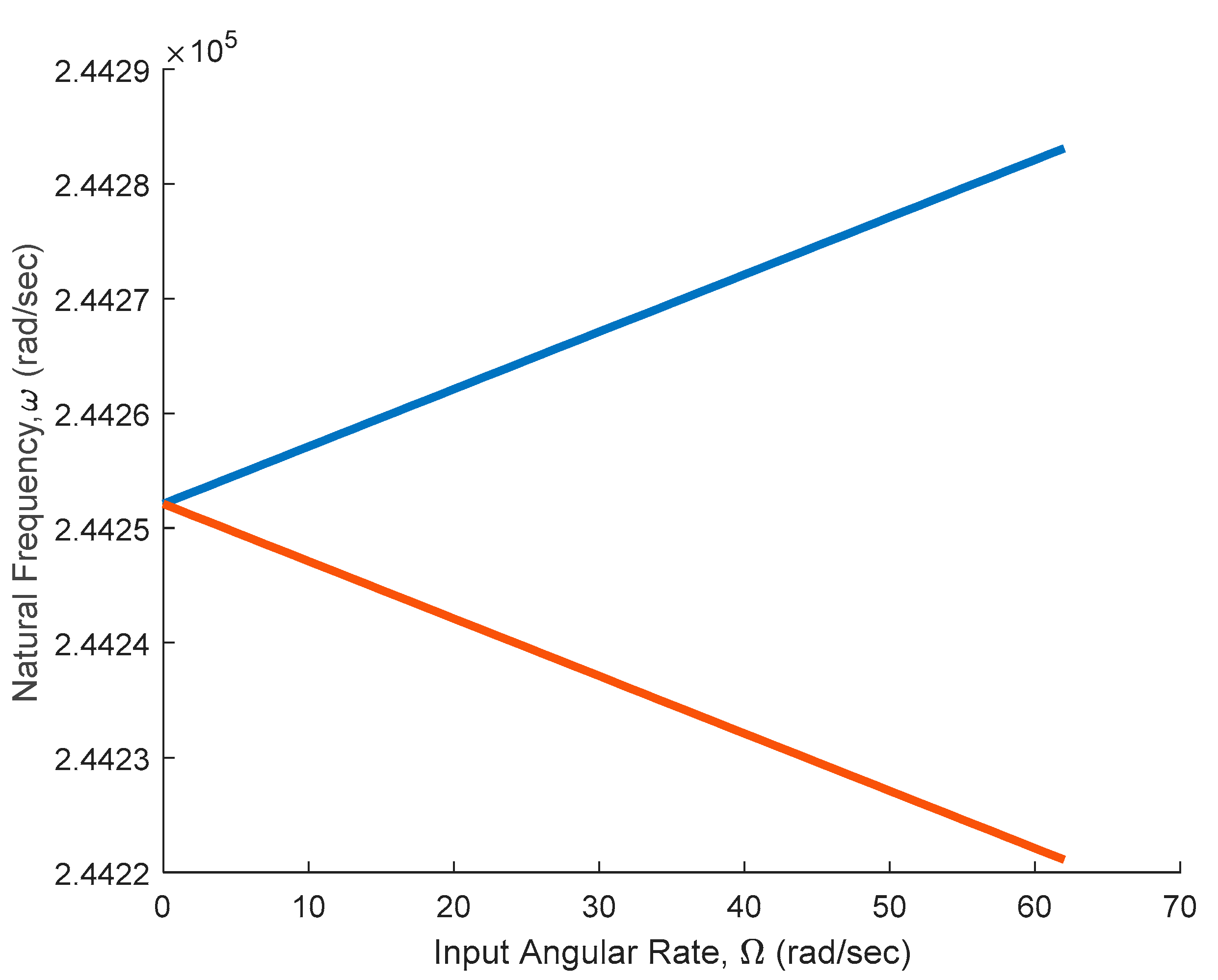
4.1. Natural Frequency Variation
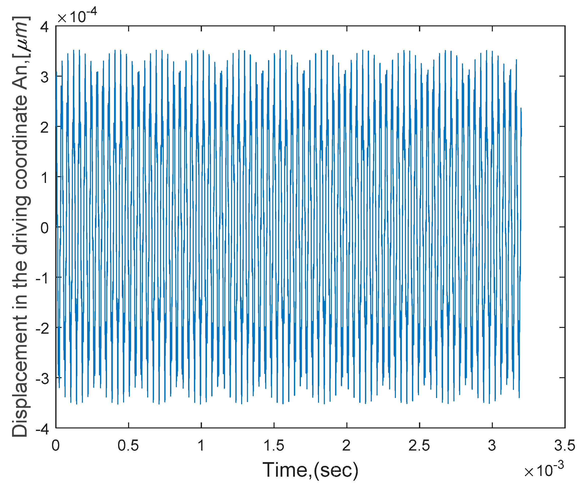
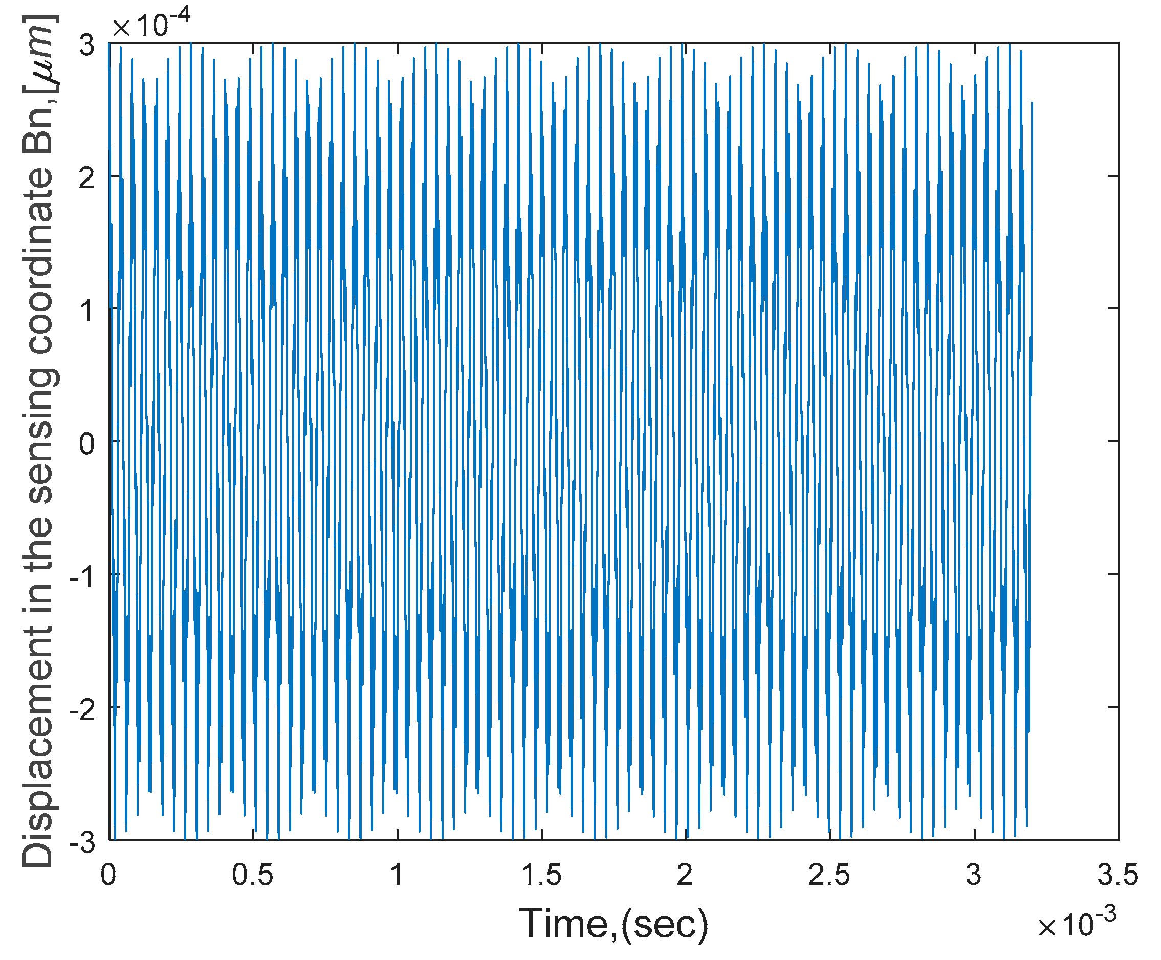
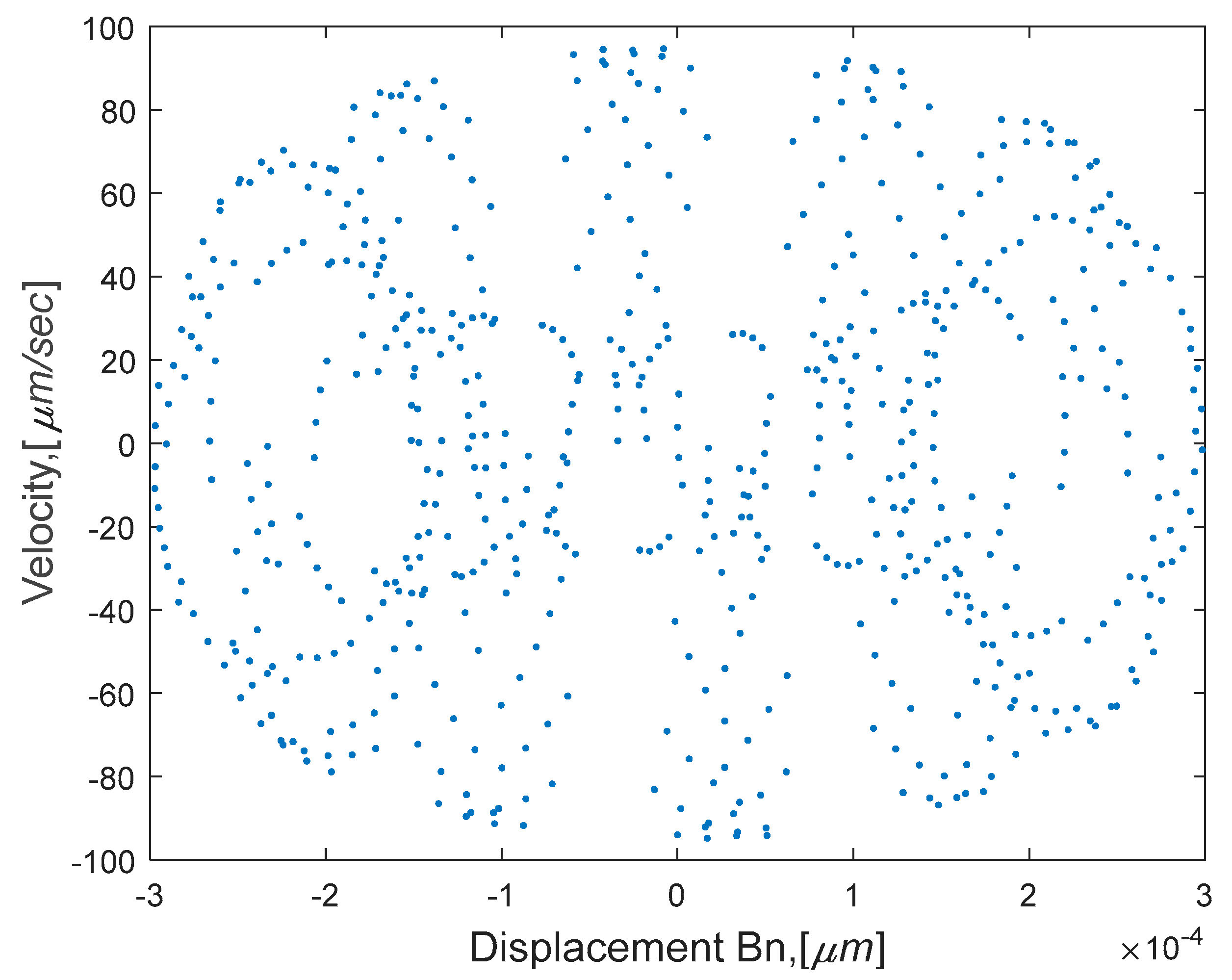
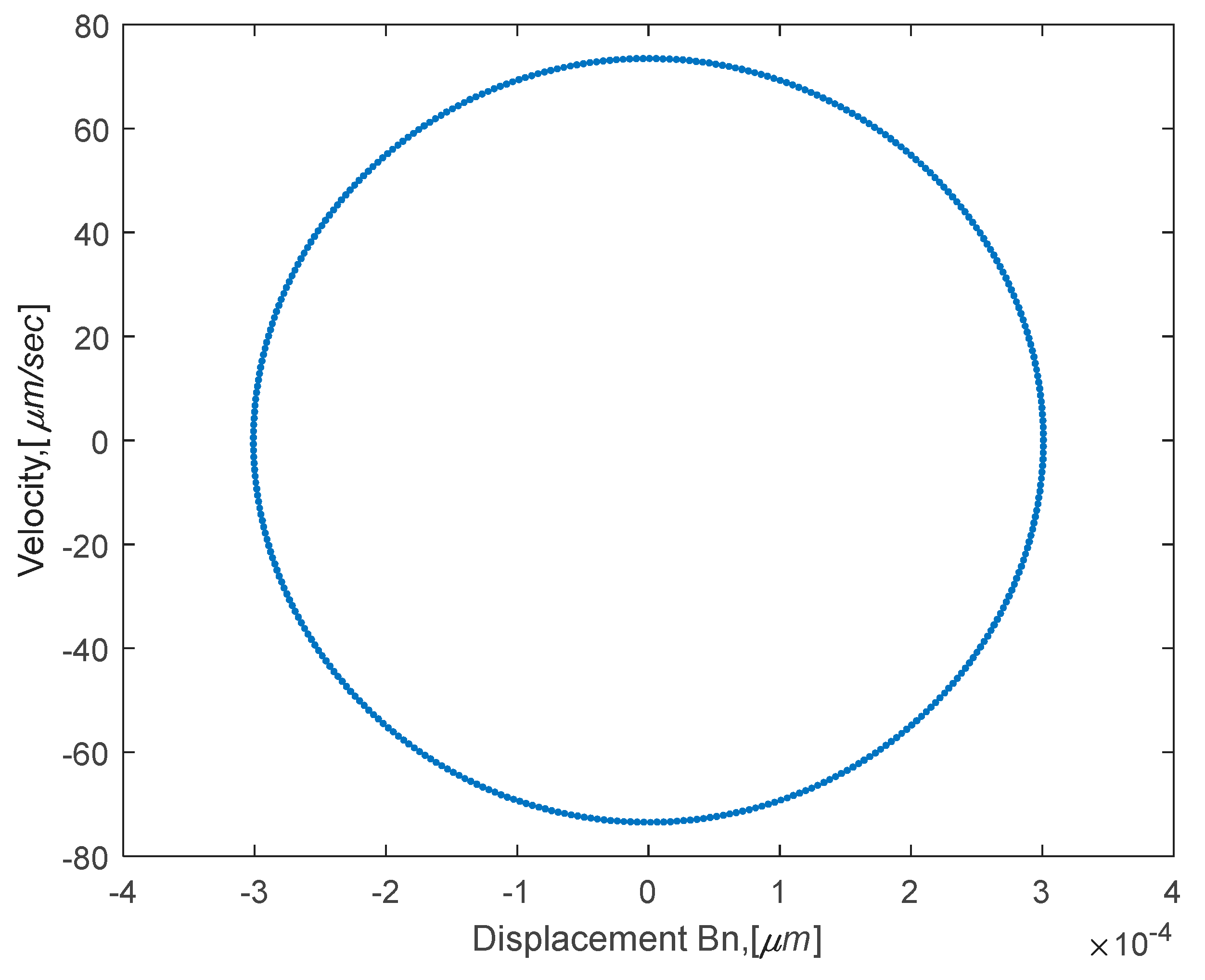
In order to illustrate the applicability of the analytical results, typical parameters associated with a MEMS ring-type angular gyroscope were considered. The following ring design parameters were chosen in the present study: radius of 500   μ m , the thickness of 12.5, height of 30 μ m with Young’s modulus of 210 Gpa , and the density of 8800 Kg / m 3 have been chosen in the present study. In addition, for all time and frequency response simulations, a damping ratio ζ of 0.0001 was assumed for the system. Figure 4 illustrates the frequency-split behavior and natural frequency variation due to changes in the input angular rates. It may be noted that the brown line represents the first natural frequency while the blue line represents the second natural frequency. At a nominal input angular rate of 2 π   rad / s , these frequencies take the values ω 1 = 2.4422 × 10 5 rad / s , and ω 2 =   2.4428 × 10 5 rad / s . It is evident from Figure 4 that as the input angular rate increases, ω 2 increases, while ω 1 decreases. In the absence of the input angular motion of the ring, the natural frequencies of the ring are identical, and ω 1 = ω 2 = 2.4425 × 10 5 rad / s .
In addition, the amplitude ratio of the displacement in the sensing direction to the displacement in the driving direction ( | B n / A n | ) was evaluated for the stationary ring, as depicted in Figure 5. It is evident from this figure that the amplitude ratio has the maximum value near the natural frequency ω 1 = ω 2 = 2.4425 × 10 5 rad / s = 38873.59   Hz . In the following sections, numerical simulation performed using ode45 solver from MATLAB is presented. Further, the convergence and stability of solutions were examined via several trial runs prior to obtaining the final simulation results.

4.2. Time Response

In the present study, comprehensive nonlinear governing equations of the flexural motion of vibrating thin circular rings presented in Equations (12) and (13) are employed to investigate the nonlinear dynamic behavior of a ring-type MEMS gyroscope. The geometry and parameters used in this study are illustrated in Figure 1. For the purposes of predicting the nonlinear response characteristic of the MEMS ring-type gyro, Equations (12) and (13) were solved numerically when   f N e s 2   = 0 . An expression for the nonlinear electrostatic force was derived in Equation (15) and used in the present study to examine the dynamic response behavior. At a nominal input angular rate of 2 π   rad / s , the frequencies used in the present study were evaluated as ω 1 =   2.4425 × 10 5 ( rad / s ), and ω 2 = 2.4425 × 10 5 ( rad / s ). The MEMS gyroscope was subjected to an input angular velocity   Ω = 2 π   ( rad / s ) , under nonlinear oscillatory electrostatic excitation; the time response of the ring in the driving direction in the presence of a nonlinear parameter is depicted in Figure 6. Further, the time response in the sensing coordinate in the presence of nonlinear terms is illustrated in Figure 7.
Figure 8 depict the phase portrait based on the steady-state response in the driving direction in the presence of nonlinear parameter in the system when the gyroscope is subjected to an input angular rate of 2 π   rad / s   . Further, the phase portrait is based on the steady-state response in the sensing direction in the presence of nonlinear parameters when the MEMS gyroscope is subjected to an input angular rate, as shown in Figure 9. It may be noted that the nonlinearities are evident from the plot in the presence of nonlinear term due to the nonlinearities of the system, as well as nonlinear electrostatic force.
Furthermore, the nonlinear behavior is also clearly seen in the Poincare map results in the driving and sensing coordinate responses, as illustrated in Figure 10 and Figure 11. Hence, it can be concluded that the multi-equilibrium points evident from the Poincare map must be considered when designing this class of devices. It is recommended that either minimization or adequate control action be exercised during operation.
In addition, to examine the effects of actuator nonlinearities, a Poincare map was constructed in the absence of the nonlinear parameter γ in Equations (12) and (13), as shown in Figure 12 and Figure 13. It should be noted that these figures show quasi-periodic behavior, and it can be concluded that the nonlinear actuator has minimal impact on the steady-state behavior owing to the absence of the nonlinear parameter γ in the inertia and stiffness terms in the model explained previously. A comparison of the nonlinear model with the linear model in the absence of nonlinear parameters revealed that the inclusion of model nonlinearities in the presence of high vibration amplitudes has a strong influence and hence significantly demonstrates its importance.

5. Conclusions

In this study, nonlinear and linear equations that govern the in-plane motion of MEMS ring-type gyroscopes have been developed to investigate the dynamic behavior for use in vibratory angular rate sensors. Numerical simulations of MEMS ring-type gyroscopes have been performed to study the dynamic response behavior of angular rate sensors. A comprehensive mathematical model representing the nonlinear dynamic behavior of ring-type MEMS vibratory angular rate sensors is derived based on a rotating ring, assuming that it is entirely symmetric. To investigate the dynamic response behavior of a ring-type MEMS vibratory angular rate, the nonlinear equations of motion are simplified by ignoring the extensional vibrations since the second resonant flexural mode is excited in this class of applications. The device exhibits high nonlinearity in the presence of the nonlinear term in the model, which may be attributed to the high vibration amplitudes. A suitable nonlinear electrostatic actuator model was developed to analyze nonlinear dynamic response analysis. The results of the dynamic response obtained via time-response, phase portraits, and Poincare’s maps indicate that the nonlinear actuation has minimal influence on the resulting steady-state behavior.

Author Contributions

I.F.G. and S.F.A. formulated and designed the system model; I.F.G. performed the numerical simulations; I.F.G. and S.F.A. analyzed the results and wrote the manuscript. All authors have read and agreed to the published version of the manuscript.

Funding

This research was funded by Natural Science and Engineering Research Council (NSERC) of Canada discovery grant (#RGPIN/250432) and scholarship awarded to the first author by the Ministry of Education and Scientific Research and Azzaytuna University, Libya.

Data Availability Statement

Not applicable.

Acknowledgments

The Natural Science and Engineering Research Council (NSERC) of Canada discovery grant and scholarship awarded to the first author by the Ministry of Education and Scientific Research and Azzaytuna University, Libya.

Conflicts of Interest

The authors declare no conflict of interest. Funding sponsors had no role in the design of the study; in the collection, analyses, or interpretation of data; in the writing of the manuscript; or in the decision to publish the results.

Appendix A

The integral formulae employed in the simplification of Equations (9) and (10):
0 2 π cos ( n θ ) d θ = 0 , 0 2 π sin ( n θ ) d θ = 0 ,
0 2 π cos ( 2 n θ ) d θ = 0 , 0 2 π sin ( 2 n θ ) d θ = 0 ,
0 2 π cos ( n θ ) sin ( n θ ) d θ = 0 ,
0 2 π cos ( 2 n θ ) cos ( n θ ) d θ = 1 2 0 2 π [ cos ( 3 n θ ) + cos ( n θ ) ] d θ = 0 ,
0 2 π cos ( 2 n θ ) sin ( n θ ) d θ = 1 2 0 2 π [ sin ( 3 n θ ) + sin ( n θ ) ] d θ = 0 ,
0 2 π sin ( 2 n θ ) cos ( n θ ) d θ = 1 2 0 2 π [ sin ( 3 n θ ) + sin ( n θ ) ] d θ = 0 ,
0 2 π sin ( 2 n θ ) sin ( n θ ) d θ = 1 2 0 2 π [ cos ( 3 n θ ) cos ( n θ ) ] d θ = 0

References

  1. Putty, M.W.; Najafi, K. A Micro Machined Vibrating Ring Gyroscope. In Solid-State Sensor and Actuator Workshop, Hilton Head, South Carolina; Clarendon: Oxford, UK, 1994; Volume 2, pp. 68–73. [Google Scholar]
  2. Evensen, D.A. Nonlinear Flexural Vibrations of Thin Circular Rings. Ph.D. Thesis, California Institute of Technology, Pasadena, CA, USA, 1964. [Google Scholar]
  3. Evensen, D.A. Nonlinear Flexural Vibrations of Thin Circular Rings. J. Appl. Mech. 1966, 33, 553–560. [Google Scholar] [CrossRef] [Green Version]
  4. Soedel, W. Vibrations of Shells and Plates; Marcel Dekker, Inc.: New York, NY, USA; Basel, Switzerland, 1981. [Google Scholar]
  5. Huang, S.; Soedel, W. Effects of coriolis acceleration on the free and forced in-plane vibrations of rotating rings on elastic foundation. J. Sound Vib. 1987, 115, 253–274. [Google Scholar] [CrossRef]
  6. Eley, R.; Fox, C.; Mcwilliam, S. Coriolis Coupling Effects on the Vibration of Rotating Rings. J. Sound Vib. 2000, 238, 459–480. [Google Scholar] [CrossRef]
  7. Bickford, W.; Reddy, E. On the in-plane vibrations of rotating rings. J. Sound Vib. 1985, 101, 13–22. [Google Scholar] [CrossRef]
  8. Zhang, D.; Wang, S.; Liu, J. Analytical Prediction for Free Response of Rotationally Ring-Shaped Periodic Structures. J. Vib. Acoust. 2014, 136, 041016. [Google Scholar] [CrossRef]
  9. Asokanthan, S.F.; Cho, J. Dynamic stability of ring-based angular rate sensors. J. Sound Vib. 2006, 295, 571–583. [Google Scholar] [CrossRef]
  10. Cho, J. Nonlinear Instabilities in Ring-Based Vibratory Angular Rate Sensors. Ph.D. Thesis, The University of Western Ontario, London, ON, Canada, 2009. [Google Scholar]
  11. Asokanthan, S.F.; Arghavan, S.; Bognash, M. Stability of Ring-Type MEMS Gyroscopes Subjected to Stochastic Angular Speed Fluctuation. J. Vib. Acoust. 2017, 139, 040904. [Google Scholar] [CrossRef]
  12. Gebrel, I.F.; Wang, L.; Asokanthan, S.F. Dynamics of a Ring-Type Macro Gyroscope under Electromagnetic External Actuation Forces. In Proceedings of the the ASME International Design Engineering Technical Conferences, Quebec City, QC, Canada, 26–29 August 2018. [Google Scholar]
  13. Gebrel, I.F.; Wang, L.; Asokanthan, S.F. Influence of Model Nonlinearities on the Dynamics of Ring-type Gyroscopes. In Proceedings of the Second International Nonlinear Dynamics Conference, NODYCON21, Roma, Italy, 16–19 February 2021. [Google Scholar]
  14. Gebrel, I.F.; Wang, L.; Asokanthan, S.F. Dynamics of MEMS-based Angular Rate Sensors Excited via External Electrostatic Forces. In Proceedings of the ASME International Mechanical Engineering Congress & Exposition IMECE 2020, Portland, OR, USA, 16–19 November 2020. [Google Scholar]
  15. Yoon, S.W.; Lee, S.; Najafi, K. Vibration sensitivity analysis of MEMS vibratory ring gyroscopes. Sens. Actuators A Phys. 2011, 171, 163–177. [Google Scholar] [CrossRef]
  16. Zhou, X.; Wu, Y.-L.; Wu, X.-Z.; Zhang, Y.-M.; Zheng, Y. A novel ring vibrating gyroscope based on side piezo-electrodes. J. Central South Univ. 2016, 23, 555–561. [Google Scholar] [CrossRef]
  17. Ouakad, H.M. Nonlinear structural behavior of a size-dependent MEMS gyroscope assuming a non-trivial shaped proof mass. Microsyst. Technol. 2019, 26, 573–582. [Google Scholar] [CrossRef]
  18. Rahmani, M.; Rahman, H.M. A novel Compound Fast Fractional Integral Sliding Mode Control and Adaptive PI Control of a MEMS Gyrscope. Microsyst. Technol. 2019, 25, 3683–3689. [Google Scholar] [CrossRef]
  19. Di Napoli, V.; McWilliam, S.; Popov, A.A. Frequency Splitting in MEMS Ring-based Coriolis Vibrating Gyroscopes Caused by Support Non-Linearity. Proceedings 2018, 2, 755. [Google Scholar] [CrossRef] [Green Version]
  20. Luo, Y.; Gebrel, I.; Bognash, M.; Pan, Y.; Liu, F.; Asokanthan, S.; Luo, H.; Qu, T. Time Response of a Cylindrical Fused Silica Resonator Subjected to Varying Input Angular Velocities. IEEE Sens. Council. 2020, 20, 3460–3468. [Google Scholar] [CrossRef]
  21. Luo, Y.; Gebrel, I.; Bognash, M.; Asokanthan, S.; Luo, H. Dynamic Considerations in the Design of Cylindrical Fused Silica Resonator Based Gyroscopes Subjected to Angular Rate Variations. IEEE Sens. Council. 2020, 1558–1748. [Google Scholar]
  22. Saghir, S.; Younis, M.I. An investigation of the mechanical behavior of initially curved microplates under electrostatic actuation. Acta Mech. 2018, 229, 2909–2922. [Google Scholar] [CrossRef]
  23. Ilyas, S.; Alfosail, F.; Bellaredj, M.L.F.; Younis, M.I. On the response of MEMS resonators under generic electrostatic loadings: Experiments and applications. Nonlinear Dyn. 2019, 95, 2263–2274. [Google Scholar] [CrossRef]
  24. Batra, R.C.; Porfiri, M.; Spinello, D. Review of modeling electrostatically actuated microelectromechanical systems. Smart Mater. Struct. 2007, 16, R23–R31. [Google Scholar] [CrossRef]
  25. Zhao, C.; Montaseri, M.H.; Wood, G.; Pu, S.H.; Seshia, A.; Kraft, M. A review on coupled MEMS resonators for sensing applications utilizing mode localization. Sens. Actuators A Phys. 2016, 249, 93–111. [Google Scholar] [CrossRef]
  26. Caruntu, D.I.; Martinez, I. Reduced order model of parametric resonance of electrostatically actuated MEMS cantilever resonators. Int. J. Non-linear Mech. 2014, 66, 28–32. [Google Scholar] [CrossRef]
  27. Hajjaj, A.; Jaber, N.; Hafiz, M.; Ilyas, S.; Younis, M. Multiple internal resonances in MEMS arch resonators. Phys. Lett. A 2018, 382, 3393–3398. [Google Scholar] [CrossRef]
  28. Gallacher, B.J.; Burdess, J.S.; Harish, K.M. A control scheme for a MEMS electrostatic resonant gyroscope excited using combined parametric excitation and harmonic forcing. J. Micromech. Microeng. 2006, 16, 320–331. [Google Scholar] [CrossRef]
  29. Nielson, G.N.; Barbastahis, G. Dynamic Pull-In of Parallel-Plate and Torsional Electrostaic MEMS Actuators. J. Microelectromech. Syst. 2006, 15, 811–821. [Google Scholar] [CrossRef]
  30. Feng, J.; Liu, C.; Zhang, W.; Han, J.; Hao, S. Mechanical Behaviors Research and the Structural Design of a Bipolar Electrostatic Actuation Microbeam Resonator. Sensors 2019, 19, 1348. [Google Scholar] [CrossRef] [Green Version]
  31. Rasekh, M.; Khadem, S. Design and performance analysis of a nanogyroscope based on electrostatic actuation and capacitive sensing. J. Sound Vib. 2013, 332, 6155–6168. [Google Scholar] [CrossRef]
  32. Chuang, W.-C.; Lee, H.-L.; Chang, P.-Z.; Hu, Y.-C. Review on the Modeling of Electrostatic MEMS. Sensors 2010, 10, 6149–6171. [Google Scholar] [CrossRef] [PubMed]
  33. Gallacher, B.J.; Hedley, J.; Burdess, J.S.; Harris, A.J.; Rickard, A.; King, D.O. Electrostaic correction of structural imperfections present in a microring gyroscope. J. Microelectromech. Syst. 2005, 14, 221–234. [Google Scholar] [CrossRef]
  34. Gorthi, S.; Mohanty, A.; Chatterjee, A. Cantilever beam electrostatic MEMS actuators beyond pull-in. J. Micromech. Microeng. 2006, 16, 1800–1810. [Google Scholar] [CrossRef] [Green Version]
  35. El-Sayed, A.M.; Ghoneima, M.; Mahmoud, M.A. Modeling of Nonlinearities in Vibration Ring Gyroscopes. In Proceedings of the Second International Japan-Egypt Conference on Electronics, Communications and Computers (JEC-ECC), Cairo, Egypt, 31 May–2 June 2016; pp. 1–57. [Google Scholar]
  36. Oropeza-Ramos, L.A.; Burgner, C.B.; Turner, K.L. Robust micro-rate sensor actuated by parametric resonance. Sens. Actuators A Phys. 2009, 152, 80–87. [Google Scholar] [CrossRef]
  37. Rabenimanana, T.; Walter, V.; Kacem, N.; Le Moal, P.; Bourbon, G.; Lardiès, J. Functionalization of electrostatic nonlinearities to overcome mode aliasing limitations in the sensitivity of mass microsensors based on energy localization. Appl. Phys. Lett. 2020, 117, 033502. [Google Scholar] [CrossRef]
  38. Kacem, N.; Hentz, S.; Baguet, S.; Dufour, R. Forced large amplitude periodic vibrations of non-linear Mathieu resonators for microgyroscope applications. Int. J. Non-Linear Mech. 2011, 46, 1347–1355. [Google Scholar] [CrossRef] [Green Version]
  39. Mahboob, I.; Dupuy, R.; Nishiguchi, K.; Fujiwara, A.; Yamaguchi, H. Hopf and period-doubling bifurcations in an electromechanical resonator. Appl. Phys. Lett. 2016, 109, 073101. [Google Scholar] [CrossRef]
  40. Han, M.; Zhang, Q.; Hao, S.; Li, W. Parametric Characteristics and Bifurcation Analysis of Multi-Degree-of-Freedom Micro Gyroscope with Drive Stiffness Nonlinearity. Micromachines 2019, 10, 578. [Google Scholar] [CrossRef] [Green Version]
  41. Asokanthan, S.F.; Wang, T. Nonlinear instabilities in a vibratory gyroscope subjected to angular speed fluctuations. Nonlinear Dyn. 2008, 54, 69–78. [Google Scholar] [CrossRef]
  42. Buono, P.L.; Chan, B.S.; Palacios, A.; In, V. Dynamics and bifurication in a Dn-symmetric Hamiltonian network Applictaion to Coupled Gyroscope. Phys. D 2015, 290, 8–23. [Google Scholar] [CrossRef]
  43. Karabalin, R.B.; Cross, M.C.; Roukes, M.L. Nonlinear dynamics and chaos in two coupled nanomechanical resonators. Phys. Rev. B 2009, 7, 165309. [Google Scholar] [CrossRef] [Green Version]
  44. Passaro, V.; Cuccovillo, A.; Vaiani, L.; Carlo, M.; Campanella, C. Gyroscope Technology and Applications: A Review in the Industrial Perspective. Sensors 2017, 7, 2284. [Google Scholar] [CrossRef] [Green Version]
  45. Bao, M. Analysis and Design Principles of MEMS Devices; Elsevier Inc.: Amsterdam, The Netherlands, 2005; pp. 175–206. ISBN 0-44451-616-6. [Google Scholar]
  46. Jearl, W.; Halliday, D.; Resnick, R. Fundamentals of Physics, 9th ed.; Cleveland State University: Cleveland, OH, USA, 2011; ISBN 978-0-470-46908-8. [Google Scholar]
  47. Younis, M.I. MEMS Linear and Nonlinear Statics and Dynamics; Springer: New York, NY, USA, 2011; pp. 1389–2134. ISBN 978-1-4419-6019-1. [Google Scholar]
Figure 1. Schematic of ring geometry.
Vibration 04 00045 g001
Figure 2. Visualization of primary direction A n and secondary direction B n of ring.
Vibration 04 00045 g002
Figure 3. A Schematic of ring and electrodes configuration.
Vibration 04 00045 g003
Figure 4. Natural frequency variations for rotating ring.
Vibration 04 00045 g004
Figure 5. Amplitude ratio of displacement | B n / A n | .
Vibration 04 00045 g005
Figure 6. Radial displacement in driving direction for A n for Ω = 2 π   rad / s in presence of nonlinear parameter γ .
Vibration 04 00045 g006
Figure 7. Radial displacement in the sensing direction B n for Ω = 2 π   rad / s in presence of nonlinear parameter γ .
Vibration 04 00045 g007
Figure 8. Phase diagram in driving direction A n for Ω = 2 π   rad / s in presence of nonlinear parameter γ .
Vibration 04 00045 g008
Figure 9. Phase diagram in sensing direction B n for Ω = 2 π   rad / s in presence of nonlinear parameter γ .
Vibration 04 00045 g009
Figure 10. Poincare’ map in driving direction A n for Ω = 2 π   rad / s in presence of nonlinear parameter γ .
Vibration 04 00045 g010
Figure 11. Poincare’ map in sensing direction B n for Ω = 2 π   rad / s in presence of nonlinear parameter γ .
Vibration 04 00045 g011
Figure 12. Poincare’ map in driving direction A n for Ω = 2 π   rad / s in absence of nonlinear parameter γ .
Vibration 04 00045 g012
Figure 13. Poincare’ map in sensing direction B n for Ω = 2 π   rad / s in absence of nonlinear parameter γ .
Vibration 04 00045 g013
Publisher’s Note: MDPI stays neutral with regard to jurisdictional claims in published maps and institutional affiliations.

