Article

Experimental Study on Impact Force Identification on a Multi-Storey Tower Structure Using Different Transducers

1
School of Mechanical and Mechatronic Engineering, University of Technology Sydney, Sydney, NSW 2007, Australia
2
Rahesh Innovation Center, Shiraz 7188711114, Iran
*
Authors to whom correspondence should be addressed.
Vibration 2021, 4(1), 101-116; https://doi.org/10.3390/vibration4010009
Submission received: 2 December 2020 / Revised: 14 January 2021 / Accepted: 25 January 2021 / Published: 29 January 2021
(This article belongs to the Special Issue Inverse Dynamics Problems)

Abstract

:
This paper presents the identification of both location and magnitude of impact forces applied on different positions of a multi-storey tower structure using different types of transducers, i.e., an accelerometer, a laser Doppler vibrometer, and a triangulation displacement sensor. Herein, a model-based inverse method is exploited to reconstruct unknown impact forces based on various recorded dynamic signals. Furthermore, the superposition approach is employed to identify the impact location. Therein, it is assumed that several impact forces are applied simultaneously on potential locations of the multi-storey tower structure, while only one impact has non-zero magnitude. The purpose is then to detect the location of that non-zero impact. The influence of using different hammer tip materials for establishing the transfer function is investigated, where it is concluded that the hammer with a harder tip leads to a more accurate transfer function. An accuracy error function is proposed to evaluate the reconstruction precision. Moreover, the effect of sensor type and location on the accuracy of the reconstruction is studied, where it is shown that the proximity between the impact and sensor locations is a dominant factor in impact force reconstruction. In addition, the efficacy of using different transducers is studied for the impact localization, where it is demonstrated that reducing the degree of under-determinacy by using a combination of system responses of the same type can improve the localization accuracy.

1. Introduction

Many structures are subjected to impact forces, which can be a matter of serious concern in terms of structural integrity. Measurement of these accidental impact forces is of great importance since it can help prevent system failure through evaluating the system stress and comparing it to its tolerance threshold or fatigue limit. Direct measurements of impact forces are difficult, expensive, and tedious, especially for large structures due to the difficulty of sensor installation and dynamic characteristic altering, while beforehand, localization of the impact area can make the examinations more efficient. Using system dynamic responses, captured by sensors placed distant from the impact location, the impact forces can be estimated by inverse algorithms.
The basis of inverse algorithms is to indirectly identify the impact force using responses measured at given points of the body subjected to impact. Inverse algorithms exploited in the literature can be categorized into two main classifications, namely, model-based techniques [1,2] and neural networks [3,4,5,6]. The superiority of neural networks emerges when the underlying dynamics is infeasibly complicated or inaccessible. However, as the accuracy of these techniques relies on massive training data, which is usually impractical, the model-based methods are more widely used. In model-based methods, a transfer function is found by utilizing the input and output of the system. Some examples of these methods are as follows: deconvolution technique [7,8,9,10,11,12,13,14], state variable formulation [15,16,17,18,19,20], and sum of weighted accelerations [21,22]. In [23], the inverse structural filter method, which leans on the dynamics state-space model, and the sum of the weighted accelerations technique are compared. Therein, deficiencies of the mentioned strategies are discussed and some modifications are proposed in order to enhance their performance. Among the model-based methods introduced, the deconvolution method has received significant attention in the literature. Two main attitudes of the deconvolution method are the time-domain [1,2,24,25] and the frequency-domain approach [26]. In [23], a comparison is made between the results of two time-domain strategies and those of a frequency-domain approach in order to determine the pros and cons of each method. Generally speaking, frequency-domain methods need lower computational efforts while they are usually infeasible for transient phenomena such as impact events. Solving a deconvolution problem might not result in a sufficiently good outcome since the force reconstruction problem is intrinsically ill-posed due to the ill-conditioned nature of the transfer function, i.e., the condition number of the transfer function matrix is very large, making the problem sensitive to small perturbations such as measurement errors or noise. To avoid divergent or inaccurate results, it is usually necessary to exploit a regularization method.
Several regularization techniques have been proposed in the literature. The most popular ones are Tikhonov regularization [27,28,29,30,31] and Singular Value Decomposition (SVD) based methods, including truncated SVD (TSVD) [27,32,33]. These two methods are compared in [34]. The theoretical backgrounds of five regularization methods, namely, generalized cross-validation, singular value decomposition, iterative method, data filtering approach, and Tikhonov regularization are introduced and main restrictions of each method are discussed in [35]. Some other exploited methods in the literature are QR factorization [36], explicit block inversion algorithms [37], Bayesian regularization [38], and the least-square QR (LSQR) iterative regularization method [39]. A combination of l 1 regularization and sparse reconstruction is proposed in [40]. In [11], a primal-dual interior point method is exploited and compared to the Tikhonov method. More recently, nonconvex sparse regularization based on generalized minimax-concave (GMC) and non-negative Bayesian learning are used in [25,41], respectively. In [42], Bayesian sparse regularization is exploited for identification and localization of multiple forces in time domain, and compared with Tikhonov regularization associated with the Generalized Cross Validation (GCV) criterion. Existing regularization methods which are proposed for force reconstruction are vector-based, while for large-scale inverse problems, matrix-based regularization has several privileges. Matrix-based regularization was recently introduced in [43] where the parameter of regularization was chosen with the Bayesian Information Criterion (BIC). Another issue that has been raised in recent years is that of moving force identification. In [44], a comparison is made between four regularization methods, i.e., (i) truncated generalized singular value decomposition (TGSVD), (ii) piecewise polynomial truncated singular value decomposition (PP-TSVD), (iii) modified preconditioned conjugate gradient (M-PCG) method, and (iv) preconditioned least-square QR-factorization (PLSQR) method, all used for reconstruction of moving forces, where it is concluded that the TGSVD method is preferred on the issue of identification accuracy. On the other hand, the M-PCG method is recommended in regard to identification efficiency.
To perform a comprehensive identification of an impact force, both its magnitude (force history) and location should be assessed. The location of the impact force is obscure in numerous cases in practice, which violates the fundamental presumption of the above mentioned methods. Various methods are introduced in the literature to localize the impact force. In [45], an experimental method is used in which an objective function is defined based on transfer functions and minimized in order to find the impact force location and in [46], a pseudo-inverse direct method is utilized to identify both the magnitude and location of the impact force. More recently, [12] pursued a similarity searching technique, and [14] introduces a superposition approach to estimate the impact location and magnitude simultaneously.
In the current paper, the identification of (i) the impact force history, and (ii) the impact location is presented. The impact force is applied on a scaled eight-storey tower structure in the laboratory. The identification is performed using recorded system outputs, i.e., the displacement, velocity, and acceleration measurements at level 3, as well as the acceleration measurement at level 8. The impact force reconstruction consists of two procedures, namely, (i) obtaining a transfer function between a reference impact force and its resulting response captured by a specific sensor, and (ii) identifying an unknown impact force using the transfer function obtained and the responses. Herein, the deconvolution technique is exploited to solve these inverse problems and the Tikhonov regularization method is used in order to deal with the ill-conditioned nature of the transfer function. To identify the impact location, the superposition approach is exploited where it is assumed that impact forces are concurrently applied on all 8 potential locations, while only one of them has a non-zero magnitude. This expresses the condition when only one impact is exerted at one of the possible locations. The actual impact location is then detected among all potential locations through an extended matrix form of the convolution equation.
The contributions of this paper are, firstly, investigating the influence of the hammer tip material on the effectiveness of the transfer function obtained, secondly, proposing an accuracy error function to evaluate the reconstruction precision, thirdly, studying the effect of sensor type and location on the accuracy of the impact force reconstruction, fourthly, using distinct sensors for the force reconstruction of different levels (i.e., using recorded signals at level 3 for the lower half of the structure and employing measurements at level 8 for the upper half), and fifthly, studying the localization accuracy based on the system responses used individually or in combination. The effectiveness of the method used for impact force reconstruction is demonstrated for all positions, with steel, soft rubber, medium rubber, and hard rubber tip hammers. The paper is organized as follows. The problem formulation is presented in Section 2. The experimental set-up is introduced in Section 3. Section 4 presents the results and discussion. Finally, the conclusions are presented in Section 5.

2. Problem Formulation

2.1. Single Impact Force Reconstruction

The impact force reconstruction consists of two procedures, namely, (i) obtaining a transfer function between a reference impact force and its resulting response captured by a specific sensor, and (ii) identifying an unknown impact force using this transfer function and the collected vibration responses. Suppose n sensors are deployed on a structure subjected to impacts to measure impact responses (e.g., displacement, velocity or acceleration) and the following assumptions hold:
  • one impact is being applied at a time,
  • structural responses are linear,
  • the impact location is known.
Then, the relation between the impact force f applied at point x and the response r measured at point y at time t is given by a convolution integral as follows:
r ( y , t ) = 0 t T s ( x , y , t ζ ) f ( x , ζ ) d ζ ,
where T s ( x , y , t ζ ) , s = 1 , n , is the transfer function between the impact force at point x and the s t h sensor at point y at time t = ζ . The discretized form of the forward model (1), which is more applicable in practice, can be written as follows:
r = T s f ,
with r R m , T s R m × m , f R m , where r is the recorded response vector, f is the vector of impact force which is to be reconstructed, and T s is the impulse response matrix, which is a lower triangular toeplitz matrix, given by
r = r ( Δ t ) r ( 2 Δ t ) r ( ( m 1 ) Δ t ) r ( m Δ t ) , f = f ( Δ t ) f ( 2 Δ t ) f ( ( m 1 ) Δ t ) f ( m Δ t ) , T s = T s ( Δ t ) 0 0 T s ( 2 Δ t ) T s ( Δ t ) 0 T s ( ( m 1 ) Δ t ) T s ( ( m 2 ) Δ t ) 0 T s ( m Δ t ) T s ( ( m 1 ) Δ t ) T s ( Δ t ) .
In (3), m is the number of samples and Δ t is the time interval, which should be small enough since the above discretization assumes that the impact force f is constant within each time interval. In other words, with a higher sampling frequency, the results given by (2) are theoretically more accurate.
The solution of (2) can be theoretically obtained by using the following least squares problem:
m i n r T s f 2 2 ,
where r is contaminated by experimental errors in practice. Moreover, T s is a matrix with a very large condition number and hence is ill-conditioned. Therefore, the problem must be regularized. The Tikhonov regularization method alternatively searches for an approximation of f through the following penalized least-squares problem:
m i n { r T s f 2 2 + δ I f 2 2 } ,
where δ 0 is the regularization parameter, determined by L-curve method, and I is the identity matrix.

2.2. Transfer Function

In order to solve (2), the transfer function T s should be obtained in advance. This is achieved by using a reference impact force, its corresponding measured response, and the following relation:
r = F t s ,
with t s R m , F R m × m , where F is a lower triangular toeplitz matrix, and t s is the vector of transfer function, as follows:
F = f ( Δ t ) 0 0 0 f ( 2 Δ t ) f ( Δ t ) 0 0 f ( ( m 1 ) Δ t ) f ( ( m 2 ) Δ t ) f ( Δ t ) 0 f ( m Δ t ) f ( ( m 1 ) Δ t ) f ( 2 Δ t ) f ( Δ t ) , t s = T s ( Δ t ) T s ( 2 Δ t ) T s ( ( m 1 ) Δ t ) T s ( m Δ t ) .
The solution of (6) can be obtained by using the following least squares problem:
m i n r F t s 2 2 .
However, in practice, the collected impact force and the measured dynamic response are associated with noise, equivalent to high-frequency components of signals. This causes matrix F to, potentially, have a large condition number, making it ill-conditioned. The large condition number of F together with presence of noise in r results in deviated transfer functions. Therefore, applying regularization is deemed necessary. Employing Tikhonov regularization method, an approximation of t s can be found instead, by the following penalized least-squares problem:
m i n { r F t s 2 2 + β I t s 2 2 } ,
with β 0 the regularization parameter, determined by the L-curve method.
Summarizing, impact force reconstruction consists of two steps:
  • obtaining the vector of transfer function t s by solving (6) (and converting it to the triangular toeplitz transfer function matrix T s ),
  • solving (2) for the unknown impact force f .
As discussed, both above problems are ill-posed. Therefore, in this paper, the Tikhonov regularization method is exploited in order to avoid the sensitivity to perturbations, which can potentially make the solution unstable.

2.3. Impact Force Location

Two approaches have been employed in the literature for impact force localization: the one-to-one approach and the superposition approach [14]. In the one-to-one approach, the impact reconstruction is performed for each pair of impact and response location, while in the superposition approach, the impact forces at all possible locations are reconstructed concurrently. Generally speaking, the superposition approach considers a superposition of responses corresponding to each impact force exerted at different locations. In the following, the superposition approach is presented more in detail.
Assuming several impact forces at various points ( i = 1 , , p ) concurrently applied to a structure, the vibration response collected by a single sensor installed at position s is, therefore, a superposition of the responses generated by each individual impact force.
r = i = 1 p T s i f i ,
where f i is the impact force applied on the location i, i = 1 , , p , and T s i is the transfer function between the location i and the s t h sensor location. Equation (10) can be written in matrix-vector form as follows:
r = T s 1 T s 2 T s p f 1 f 2 f p .
The procedure for creating the transfer functions were already discussed in Section 2.2. For brevity, (11) is presented by r = T s f . As previously pointed out, matrix T s is ill-conditioned and vector r is contaminated with noise, necessitating applying regularization to solve for f . Similar to (5), Tikhonov regularization is implemented. It is worth mentioning that (11) is severly under-determined, as there is one equation with p unknown forces. Now, let us make an important assumption that is the magnitude of all impact forces but one is actually equal to zero. This condition entails that an impact occurs at only one location. The purpose is, therefore, to detect the actual impact location among all potential locations, together with its force history. Using this approach, a reconstructed impact force is obtained for each potential impact location. In other words, p impact forces, i.e., f 1 , f 2 , f p , are reconstructed, keeping in mind that there is only one actual non-zero impact force. The reconstructed impact forces at spurious locations are expected to have zero magnitude as no impact has actually occurred at these locations. However, there might be some non-zero reconstructed impact forces at spurious locations. The reconstructed force at each location is qualitatively assessed, addressing key characteristics of a normal impact force such as the shape and the maximum amplitude of the first peak if applicable. A normal impact force has typically a smooth half-sine shape. More comprehensive description of this method as well as various case studies can be found in previous works of the authors [10,12,14]. Figure 1 shows a schematic of the problem.

3. Experimental Set-Up

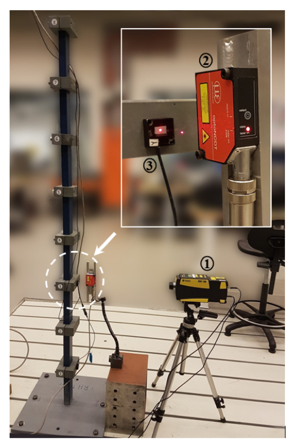
To investigate the impact force reconstruction experimentally, the structure shown in Figure 2 is used with the parameters given in Table 1. The structure is a hollow rectangular steel beam, fixed at the bottom and free at the top, on which eight lumped masses are clamped at equally distributed distances. In the following, these masses are called level 1 to 8 with level 1 at the bottom and level 8 at the top.
Four sensors, namely, two DC-response MEMS accelerometers (Measurement Specialties 4000A-005) at level 3 and level 8, a laser Doppler vibrometer (Polytec PDV-100) at level 3, and a laser triangulation sensor (Micro-Epsilon optoNCDT 1302, ILD 1302-50) at level 3 were employed to gauge system responses, as shown in Figure 2.
The impact forces were applied by a modally tuned instrumented impact hammer that provided the measurement of the actual dynamic load. This hammer was used with different tips (i.e., steel, hard rubber, medium rubber, and soft rubber tips) in order to simulate various hit modes.

4. Results and Discussion

4.1. Effect of Regularization

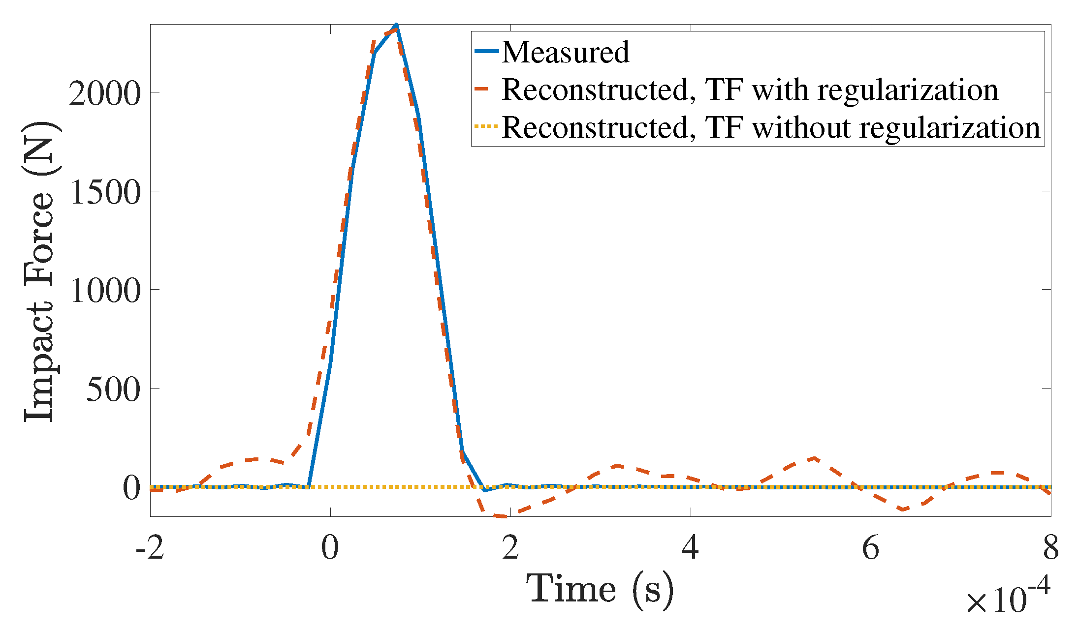
As stated previously, identification of transfer functions as well as reconstruction of impact forces are both ill-posed problems. Solving (6) using the least-square technique without applying regularization, given in (8), led to transfer functions with magnitudes in the order of 10 3 , while solving the problem considering regularization, defined in (9), gave the transfer functions with magnitudes in the order of 10 5 . Figure 3 depicts the reconstructed impact force implementing the transfer function obtained with and without regularization. In this figure, the impact force was applied at level 5, and the vibration response was measured in level 8. As seen in Figure 3, the reconstruction process utilizing the transfer function obtained without regularization yields a reconstructed impact force with virtually zero amplitude. This is because the transfer function has large singular values. The large singular values are inverted through the inverse algorithm, causing the reconstructed force to approach zero.

4.2. Establishing the Transfer Function

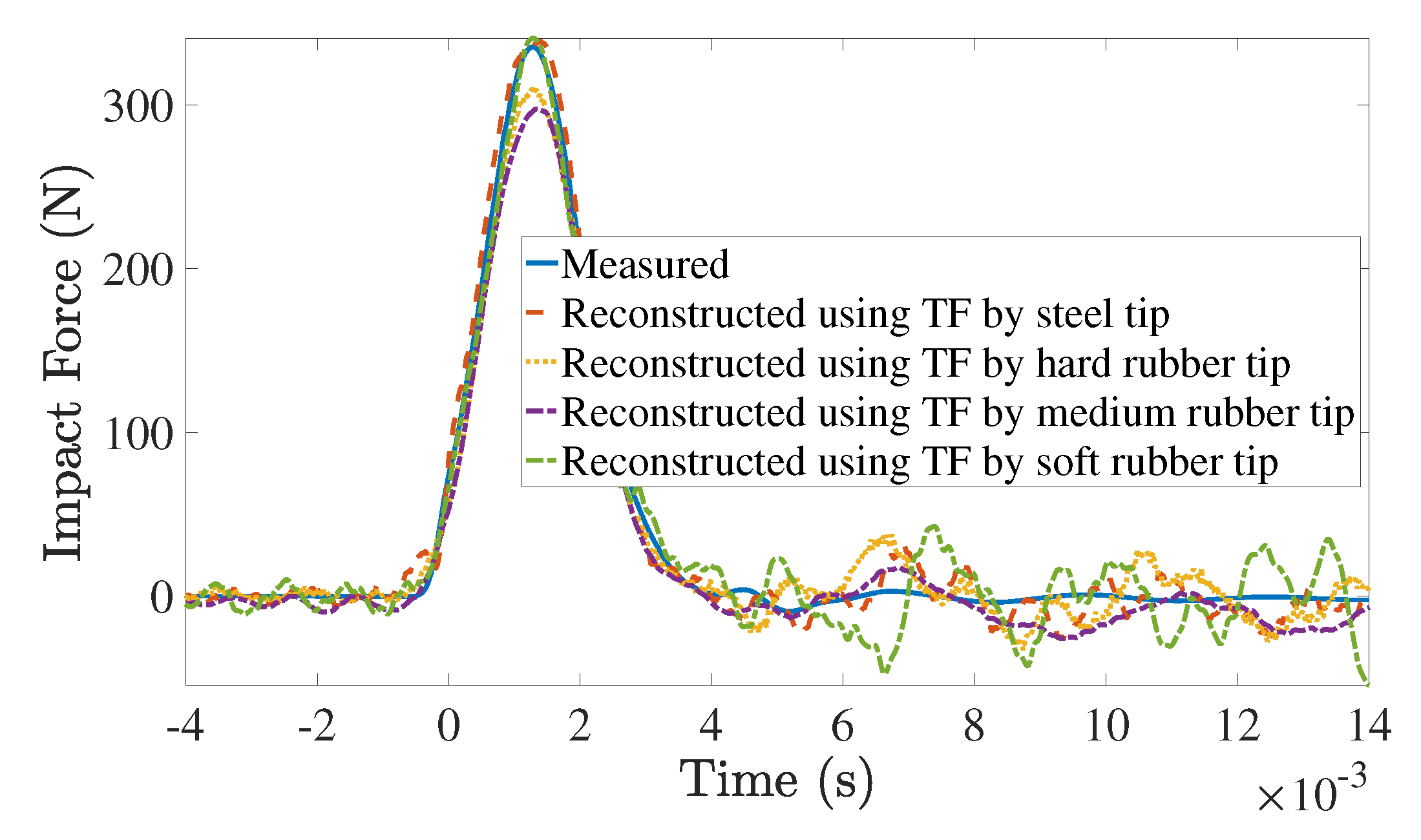
Different hammer tips can produce different half-sine shapes of impact force, with different rising patterns and time durations. As shown in Figure 4, harder tips produce sharper graphs of impact force, i.e., closer to the graph of Dirac delta function. The sharpest graph shows the results of the hammer with the hardest tip (steel tip), which, theoretically, should result in the most accurate transfer function. This result is also shown illustratively in Figure 5 in which the impact force applied by the soft rubber tip at level 4 is reconstructed by using the measured acceleration at level 8 and different transfer functions established, namely, by the steel tip, the hard rubber tip, the medium rubber tip, and the soft rubber tip itself. As can be seen, the transfer function obtained by the steel tip gives the most accurate force reconstruction result. Quantitatively, the correlation coefficient between the measured impact force and the corresponding reconstructed forces, shown in Figure 5, are 0.9917, 0.9829, 0.9917, and 0.9752, respectively, for the steel tip, the hard rubber tip, the medium rubber tip, and the soft rubber tip. Additionally, the percentage of peak errors are, respectively, 1.12 % , 7.50 % , 11.29 % , and 1.58 % . Interestingly, the best force reconstruction is not necessarily achieved when the transfer function is obtained with the same tip as the tip generating force. Even if that were the case, it would not be applicable as the material of the object impacting the structure is usually not known or predictable in practice.
To show the effectiveness of the force reconstruction, two quantities, correlation coefficient and peak error, should be considered simultaneously. In other words, the force reconstruction with a higher correlation coefficient (i.e., closer to 1), and concurrently, lower peak error (i.e., closer to 0 % ) is more desirable. Therefore, we introduce the following reconstruction accuracy error in order to use only one variable:
e = ( c o r r e l a t i o n c o e f f i c i e n t 1 ) 2 + ( p e a k e r r o r ) 2 .
In the worst case scenario, the maximum value of the accuracy error is 2 . On the other hand, when e is closer to zero, the reconstruction is more precise. For instance, in Figure 5, the reconstruction accuracy errors for steel tip, hard rubber tip, and medium rubber tip are 0.0139, 0.0769, and 0.1132, respectively, which shows the reconstruction precision in the case of steel tip as its corresponding accuracy error is closer to zero. Similar results were observed for impact at other levels. It is worth mentioning that neither the correlation coefficient nor the peak error can singly lead to this conclusion. As concluded from the above discussion, from now on, the transfer functions are established by using the steel tip hammer.

4.3. Influence of Sensor Type and Location

As previously pointed out in Section 3, four transducers are mounted on the experimental set-up, measuring the displacement, velocity, and acceleration at level 3, as well as the acceleration at level 8. These measurements can be utilized in combination or individually for the force reconstruction.
Figure 6 shows the reconstruction of the impact forces applied by steel tip hammer implementing different system responses (i.e., the velocity at level 3, acceleration at level 3, and acceleration at level 8). Since the results of using displacement at level 3 were not satisfactory at all, these are not shown for better clarity. To investigate this comparison quantitatively, Table 2 shows the values of the accuracy error for each condition, as well.
As shown in Figure 6 and Table 2, the distance between the impact location and the sensor location is a dominant factor in impact force reconstruction. More specifically, employing velocity measurement at level 3 leads to better reconstruction results for impacts at lower levels (1, 2, 3, and 4). On the other hand, to reconstruct impact forces applied at higher levels (5, 6, 7, and 8), using the acceleration measurement at level 8 is more effective. Note that the minimum accuracy error in each row is colored in Table 2.
It is observed that making the problem over-determined (e.g., employing a combination of velocity at level 3 and acceleration at level 8) does not necessarily improve the reconstruction. Therefore, in this paper, the problem is kept even-determined in order not to use extra ineffective computation costs. In this regard, the impact forces will be reconstructed by using the velocity measurement at level 3 when the impact location is in the lower half of the structure and employing the acceleration measurement at level 8, otherwise.
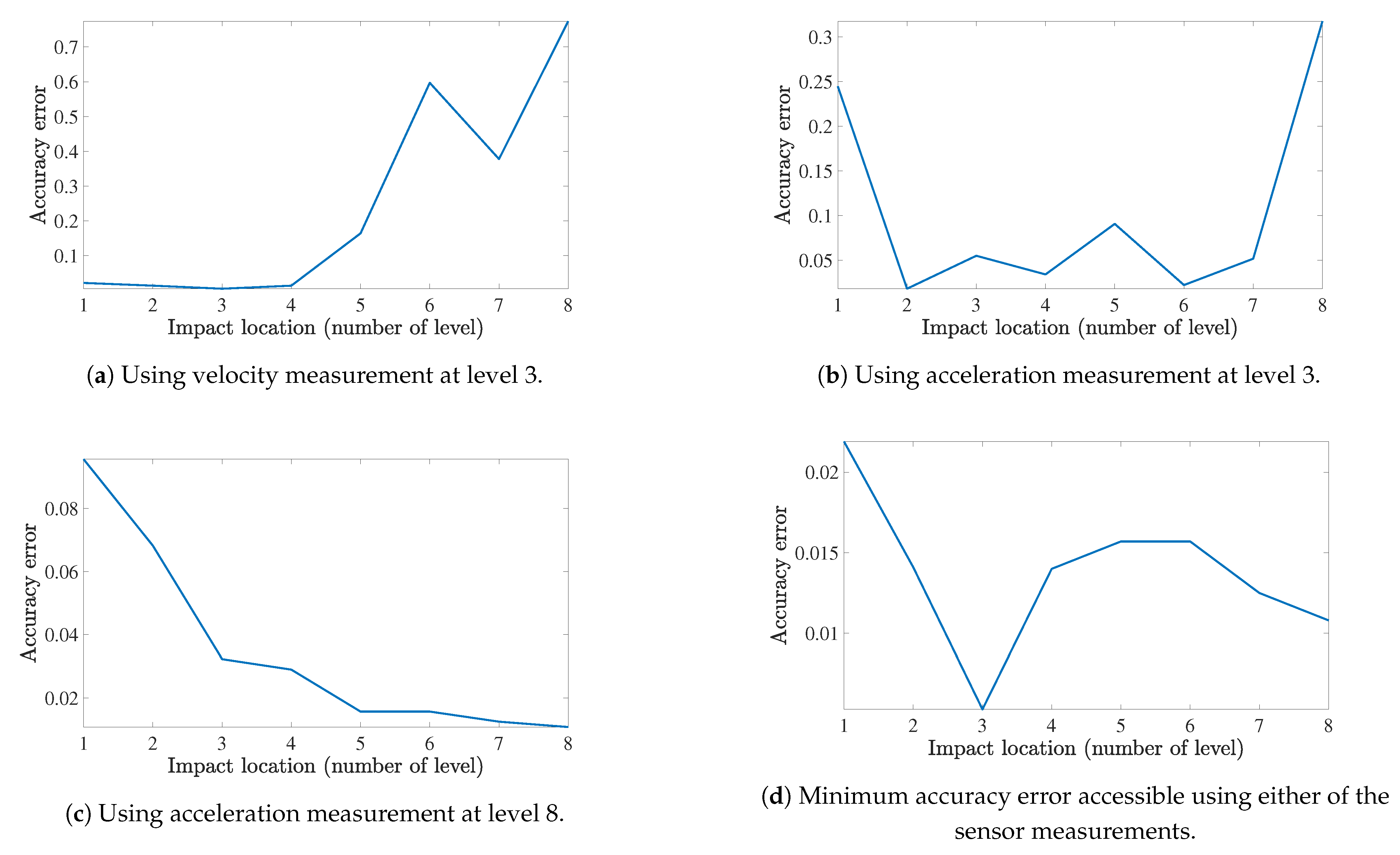
Figure 7 illustrates the reconstruction accuracy errors for impact forces applied on different levels of the structure. As shown in Figure 7a, when using the velocity measurement at level 3, the minimum of the accuracy error occurs when the impact force is applied at level 3. Similarly, when it comes to using the acceleration measurement at level 8, the accuracy error is the minimum if the impact location is also at level 8, as illustrated in Figure 7c. Concerning the acceleration measurement at level 3, it gives its most accurate result for mid-levels (not end-levels), as can be seen in Figure 7b. Figure 7d shows the accuracy error when using the velocity at level 3 for the lower half of the structure (i.e., level 1 to 4), and employing the acceleration at level 8 for the upper half (i.e., level 5 to 8). As can be seen both in Figure 7d and Table 2, the reconstruction is poorer when the impact force is applied at level 1. The reason is that this level is very close to the fixed support, which prevents the proper stimulation of vibration modes and hence the signal can not satisfactorily be captured by sensors placed distant from this location. On the other hand, the most accurate results are obtained at levels 3 and 8, exactly where the transducers are placed, which demonstrates the effect of proximity of impact location and sensor location.
In order to complement the above discussion, the impact forces applied by different rubber tip hammers (i.e., soft, medium, and hard rubber tips) are reconstructed in the following. Note that based on the conclusion made in Section 4.2, the transfer functions are obtained by using the steel tip hammer. Additionally, based on the conclusion made earlier in the current subsection, the velocity measurement at level 3 and the acceleration measurement at level 8 are employed for lower half and upper half of the structure, respectively. Table 3 shows the accuracy errors of the reconstruction for each rubber hammer tip at different levels. These errors could be reduced by manually changing the regularization parameter, however, it was not the purpose of the current paper. As shown, the accuracy error is acceptable in most of the cases, which demonstrates the efficacy of the transfer function obtained and the responses used.

4.4. Impact Force Location

In the following results, it is assumed that eight impact forces are applied concurrently at levels 1 to 8, while the magnitude of only one impact force is non-zero. Herein, the superposition approach introduced in Section 2.3 is employed for location identification. Different scenarios were tested, namely, (i) using each of the available measurements singly, and (ii) different combinations of two system responses. Among all, the combination of the acceleration at level 3 and the acceleration at level 8 leads to the most satisfactory impact localization. This is shown quantitatively in Table 4, where the accuracy errors corresponding to the reconstruction of the actual impact forces are presented for all above-mentioned scenarios. The minimum possible accuracy error for each impact location is colored in the table. As demonstrated, for most levels, the minimum occurs when the combination of acceleration at level 3 and acceleration at level 8 is employed. It is concluded that reducing the degree of under-determinacy can improve the localization accuracy. Moreover, it seems that when the two measurements, selected in combination, are of the same type, the impact force can be localized more accurately. Therefore, the actual impact location can be detected through the following relation:
r 3 r 8 = T 3 1 T 3 2 T 3 8 T 8 1 T 8 2 T 8 8 f 1 f 2 f 8 ,
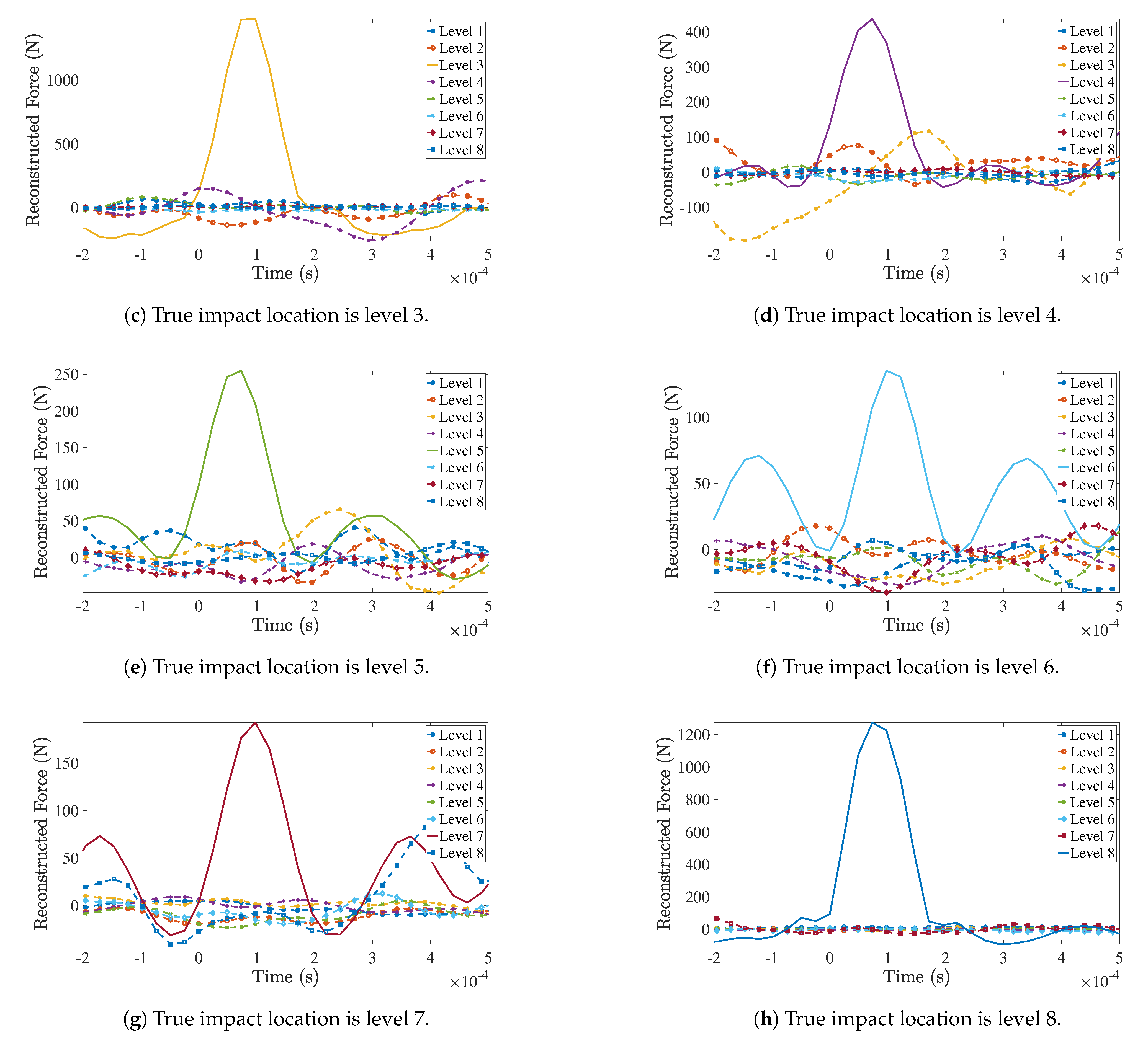
where r 3 and r 8 are the acceleration response at level 3 and 8, respectively, and T j i is the transfer function between the impact location i, i = 1 , , 8 , and measurement location j, j = 3 , 8 . As presented in Section 2.3, (13) is solved for f i , i = 1 , , 8 , where the magnitude of one of these reconstructed forces is significantly greater that others which specifies the actual impact location.
Figure 8 shows the reconstruction of impact forces at all possible locations when the actual impact force is applied at levels 1 to 8, individually, and a combination of the acceleration at level 3 and the acceleration at level 8 is considered as the system response. It demonstrates the efficacy of the approach as the reconstructed impact force associated to the true impact location has a smooth half-sine shape with a higher peak amplitude than other possible locations, as expected.

5. Conclusions

Inverse identification of an impact force acting on a multi-storey tower structure was studied experimentally using dynamic signals measured by different transducers. Herein, both the magnitude and location of the impact force were investigated. It was shown that using the hammer with the hardest tip can lead to a more accurate transfer function, where an accuracy error function was proposed to evaluate the reconstruction precision as a function of the correlation coefficient and the peak error. Moreover, it was observed that the proximity between the impact and sensor locations is a dominant factor in impact force reconstruction. Therefore, the velocity measurement at level 3 was used for the lower half of the structure and the acceleration measurement at level 8 was employed for the upper half and the effectiveness of this idea for impact force reconstruction at all positions was demonstrated both for steel tip hammer and rubber tip hammers. For impact localization, the superposition method was exploited, where the effect of different transducers was studied. It was concluded that reducing the degree of under-determinacy by using a combination of system responses of the same type can improve the localization accuracy. Therefore, a combination of the acceleration at level 3 and the acceleration at level 8 was employed for the localization.
As a potential real-world application of this study, identification of impact forces on bridge structures can be of great interest to the bridge owners and engineers. The bridge can be modelled as a multi-degree of freedom system with the expansion joints of the bridge deck taken as the potential impact locations. Measurement of the vibration response generated by the impact of heavy trucks can be carried out using accelerometers or contactless sensors such LDVs installed distant from the impact location. Another possible application of the current study is in oil-well drilling industry. During the whirling motion, the rotating drill string strikes the borehole wall, generating shocks from lateral vibrations. The location and magnitude of these impact forces are unknown as it is indeed impossible to place sensors on the string. However, using top-side measurements and inverse algorithms, the impact force can be identified, which helps in stability analysis and controller design for such structures.

Author Contributions

Conceptualization, H.K.; Formal analysis, S.T.; methodology, H.K. and S.T.; software, H.K. and B.H.; validation, H.K. and S.T.; supervision, H.K.; writing—original draft preparation, H.K. and S.T.; writing—review and editing, H.K. and S.T.; project administration, H.K. and B.H.; funding acquisition, B.H. All authors have read and agreed to the published version of the manuscript.

Funding

This research received no external funding.

Institutional Review Board Statement

Not applicable.

Informed Consent Statement

Not applicable.

Conflicts of Interest

The authors declare no conflict of interest.

References

  1. Qiao, B.; Mao, Z.; Liu, J.; Zhao, Z.; Chen, X. Group sparse regularization for impact force identification in time domain. J. Sound Vib. 2019, 445, 44–63. [Google Scholar] [CrossRef]
  2. Qiu, B.; Zhang, M.; Li, X.; Qu, X.; Tong, F. Unknown impact force localisation and reconstruction in experimental plate structure using time-series analysis and pattern recognition. Int. J. Mech. Sci. 2020, 166, 105231. [Google Scholar] [CrossRef]
  3. Sung, D.U.; Oh, J.H.; Kim, C.G.; Hong, C.S. Impact monitoring of smart composite laminates using neural network and wavelet analysis. J. Intell. Mater. Syst. Struct. 2000, 11, 180–190. [Google Scholar] [CrossRef]
  4. LeClerc, J.; Worden, K.; Staszewski, W.J.; Haywood, J. Impact detection in an aircraft composite panel—A neural-network approach. J. Sound Vib. 2007, 299, 672–682. [Google Scholar] [CrossRef]
  5. Sarego, G.; Zaccariotto, M.; Galvanetto, U. Artificial neural networks for impact force reconstruction on composite plates. In Proceedings of the 2017 IEEE International Workshop on Metrology for AeroSpace (MetroAeroSpace), Padua, Italy, 21–23 June 2017; pp. 211–216. [Google Scholar]
  6. Sarego, G.; Zaccariotto, M.; Galvanetto, U. Artificial neural networks for impact force reconstruction on composite plates and relevant uncertainty propagation. IEEE Aerosp. Electron. Syst. Mag. 2018, 33, 38–47. [Google Scholar] [CrossRef]
  7. Jacquelin, E.; Bennani, A.; Hamelin, P. Force reconstruction: Analysis and regularization of a deconvolution problem. J. Sound Vib. 2003, 265, 81–107. [Google Scholar] [CrossRef]
  8. Kalhori, H.; Ye, L.; Mustapha, S.; Li, J. Impact force reconstruction on a concrete deck using a deconvolution approach. In Proceedings of the 8th Australasian Congress on Applied Mechanics: ACAM 8, Engineers Australia, Melbourne, Australia, 23–26 November 2014; p. 763. [Google Scholar]
  9. Kalhori, H.; Ye, L.; Mustapha, S.; Li, J.; Li, B. Reconstruction and analysis of impact forces on a steel-beam-reinforced concrete deck. Exp. Mech. 2016, 56, 1547–1558. [Google Scholar] [CrossRef]
  10. Kalhori, H.; Ye, L.; Mustapha, S. Inverse estimation of impact force on a composite panel using a single piezoelectric sensor. J. Intell. Mater. Syst. Struct. 2017, 28, 799–810. [Google Scholar] [CrossRef]
  11. Qiao, B.; Zhang, X.; Gao, J.; Liu, R.; Chen, X. Sparse deconvolution for the large-scale ill-posed inverse problem of impact force reconstruction. Mech. Syst. Signal Process. 2017, 83, 93–115. [Google Scholar]
  12. Kalhori, H.; Alamdari, M.M.; Ye, L. Automated algorithm for impact force identification using cosine similarity searching. Measurement 2018, 122, 648–657. [Google Scholar] [CrossRef]
  13. Tran, H.; Inoue, H. Development of wavelet deconvolution technique for impact force reconstruction: Application to reconstruction of impact force acting on a load-cell. Int. J. Impact Eng. 2018, 122, 137–147. [Google Scholar] [CrossRef]
  14. Kalhori, H.; Alamdari, M.M.; Li, B.; Halkon, B.; Hosseini, S.M.; Ye, L.; Li, Z. Concurrent Identification of Impact Location and Force Magnitude on a Composite Panel. Int. J. Struct. Stab. Dyn. 2020, 20, 2042004. [Google Scholar] [CrossRef]
  15. Hollandsworth, P.; Busby, H. Impact force identification using the general inverse technique. Int. J. Impact Eng. 1989, 8, 315–322. [Google Scholar] [CrossRef]
  16. Law, S.S.; Fang, Y. Moving force identification: Optimal state estimation approach. J. Sound Vib. 2001, 239, 233–254. [Google Scholar] [CrossRef]
  17. Lourens, E.; Reynders, E.; De Roeck, G.; Degrande, G.; Lombaert, G. An augmented Kalman filter for force identification in structural dynamics. Mech. Syst. Signal Process. 2012, 27, 446–460. [Google Scholar]
  18. Ding, Y.; Law, S.; Wu, B.; Xu, G.; Lin, Q.; Jiang, H.; Miao, Q. Average acceleration discrete algorithm for force identification in state space. Eng. Struct. 2013, 56, 1880–1892. [Google Scholar]
  19. Wang, T.; Wan, Z.; Wang, X.; Hu, Y. A novel state space method for force identification based on the Galerkin weak formulation. Comput. Struct. 2015, 157, 132–141. [Google Scholar] [CrossRef]
  20. Liu, J.; Xie, J.; Li, B.; Hu, B. Regularized Cubic B-Spline Collocation Method With Modified L-Curve Criterion for Impact Force Identification. IEEE Access 2020, 8, 36337–36349. [Google Scholar] [CrossRef]
  21. Kreitinger, T.; Wang, M.; Schreyer, H. Non-parametric force identification from structural response. Soil Dyn. Earthq. Eng. 1992, 11, 269–277. [Google Scholar]
  22. Carne, T.G.; Mayes, R.L.; Bateman, V.I. Force Reconstruction Using the Sum of Weighted Accelerations Technique—Max-Flat Procedure; Technical Report; Sandia National Labs.: Albuquerque, NM, USA, 1993. [Google Scholar]
  23. Allen, M.; Carne, T. Comparison of inverse structural filter (ISF) and sum of weighted accelerations (SWAT) time domain force identification methods. In Proceedings of the 47th AIAA/ASME/ASCE/AHS/ASC Structures, Structural Dynamics, and Materials Conference 14th AIAA/ASME/AHS Adaptive Structures Conference 7th, Newport, RI, USA, 1–4 May 2006; p. 1885. [Google Scholar]
  24. Shiozaki, H.; Geluk, T.; Daenen, F.; Iwanaga, Y.; Van Herbruggen, J. Time-Domain Transfer Path Analysis for Transient Phenomena Applied to Tip-In/Tip-Out (Shock & Jerk); Technical Report, SAE Technical Paper; SAE: Warrendale, PA, USA, 2012. [Google Scholar]
  25. Yan, G.; Sun, H. A non-negative Bayesian learning method for impact force reconstruction. J. Sound Vib. 2019, 457, 354–367. [Google Scholar] [CrossRef]
  26. Liu, Y.; Shepard, W.S., Jr. Dynamic force identification based on enhanced least squares and total least-squares schemes in the frequency domain. J. Sound Vib. 2005, 282, 37–60. [Google Scholar] [CrossRef]
  27. Thite, A.; Thompson, D. The quantification of structure-borne transmission paths by inverse methods. Part 2: Use of regularization techniques. J. Sound Vib. 2003, 264, 433–451. [Google Scholar] [CrossRef]
  28. Nordström, L.J. A dynamic programming algorithm for input estimation on linear time-variant systems. Comput. Methods Appl. Mech. Eng. 2006, 195, 6407–6427. [Google Scholar] [CrossRef]
  29. Ronasi, H.; Johansson, H.; Larsson, F. A numerical framework for load identification and regularization with application to rolling disc problem. Comput. Struct. 2011, 89, 38–47. [Google Scholar] [CrossRef]
  30. Feng, D.; Feng, M.Q. Identification of structural stiffness and excitation forces in time domain using noncontact vision-based displacement measurement. J. Sound Vib. 2017, 406, 15–28. [Google Scholar] [CrossRef]
  31. Pan, C.D.; Yu, L.; Liu, H.L. Identification of moving vehicle forces on bridge structures via moving average Tikhonov regularization. Smart Mater. Struct. 2017, 26, 085041. [Google Scholar] [CrossRef]
  32. Leclere, Q.; Pezerat, C.; Laulagnet, B.; Polac, L. Indirect measurement of main bearing loads in an operating diesel engine. J. Sound Vib. 2005, 286, 341–361. [Google Scholar] [CrossRef]
  33. Liu, J.; Sun, X.; Han, X.; Jiang, C.; Yu, D. A novel computational inverse technique for load identification using the shape function method of moving least square fitting. Comput. Struct. 2014, 144, 127–137. [Google Scholar] [CrossRef]
  34. Miao, B.; Zhou, F.; Jiang, C.; Chen, X.; Yang, S. A comparative study of regularization method in structure load identification. Shock Vib. 2018, 2018. [Google Scholar] [CrossRef]
  35. Uhl, T. The inverse identification problem and its technical application. Arch. Appl. Mech. 2007, 77, 325–337. [Google Scholar] [CrossRef]
  36. Nordberg, T.P.; Gustafsson, I. Using QR factorization and SVD to solve input estimation problems in structural dynamics. Comput. Methods Appl. Mech. Eng. 2006, 195, 5891–5908. [Google Scholar] [CrossRef]
  37. Nordberg, T.P.; Gustafsson, I. Dynamic regularization of input estimation problems by explicit block inversion. Comput. Methods Appl. Mech. Eng. 2006, 195, 5877–5890. [Google Scholar] [CrossRef]
  38. Feng, D.; Sun, H.; Feng, M.Q. Simultaneous identification of bridge structural parameters and vehicle loads. Comput. Struct. 2015, 157, 76–88. [Google Scholar] [CrossRef]
  39. Liu, J.; Meng, X.; Jiang, C.; Han, X.; Zhang, D. Time-domain Galerkin method for dynamic load identification. Int. J. Numer. Methods Eng. 2016, 105, 620–640. [Google Scholar] [CrossRef]
  40. Qiao, B.; Zhang, X.; Wang, C.; Zhang, H.; Chen, X. Sparse regularization for force identification using dictionaries. J. Sound Vib. 2016, 368, 71–86. [Google Scholar] [CrossRef]
  41. Liu, J.; Qiao, B.; He, W.; Yang, Z.; Chen, X. Impact force identification via sparse regularization with generalized minimax-concave penalty. J. Sound Vib. 2020, 484, 115530. [Google Scholar] [CrossRef]
  42. Samagassi, S.; Jacquelin, E.; Khamlichi, A.; Sylla, M. Bayesian sparse regularization for multiple force identification and location in time domain. Inverse Probl. Sci. Eng. 2019, 27, 1221–1262. [Google Scholar] [CrossRef] [Green Version]
  43. Pan, C.; Ye, X.; Zhou, J.; Sun, Z. Matrix regularization-based method for large-scale inverse problem of force identification. Mech. Syst. Signal Process. 2020, 140, 106698. [Google Scholar] [CrossRef]
  44. Chen, Z.; Chan, T.H.; Yu, L. Comparison of regularization methods for moving force identification with ill-posed problems. J. Sound Vib. 2020, 478, 115349. [Google Scholar] [CrossRef]
  45. Boukria, Z.; Perrotin, P.; Bennani, A. Experimental impact force location and identification using inverse problems: Application for a circular plate. Int. J. Mech. 2011, 5, 48–55. [Google Scholar]
  46. Hundhausen, R.J.; Adams, D.E.; Derriso, M. Impact loads identification in standoff metallic thermal protection system panels. J. Intell. Mater. Syst. Struct. 2007, 18, 531–541. [Google Scholar] [CrossRef]
Figure 1. Schematic of impact force localization using the superposition approach.
Vibration 04 00009 g001
Figure 2. Experimentalset-up showing the multi-storey tower and primary response transducers including (1) laser Doppler vibrometer, (2) laser triangulation sensor, and (3) accelerometer.
Vibration 04 00009 g002
Figure 3. The effect of regularization in establishing the transfer function and reconstructing the impact force.
Vibration 04 00009 g003
Figure 4. Impact force graphs produced using different hammer tips.
Vibration 04 00009 g004
Figure 5. Impact force reconstruction using transfer functions (TF) established by different hammer tips.
Vibration 04 00009 g005
Figure 6. Using different transducers for impact force reconstruction at different locations.
Vibration 04 00009 g006
Figure 7. Relation between the sensor location and impact force reconstruction accuracy error.
Vibration 04 00009 g007
Figure 8. Identification of the impact location.
Vibration 04 00009 g008aVibration 04 00009 g008b
Table 1. Experimental set-up parameters.
ParameterValue
Beam length2 m
Beam cross-section65.3 × 35 mm 2
Beam thickness2.5 mm
Lumped masses dimension128× 98 × 50 mm 3
Lumped masses weight4 kg
Lumped masses distances250 mm
Table 2. Accuracy errors of impact force reconstruction using different system responses.
Impact LocationMeasured Response
Vel. at Level 3Acc. at Level 3Acc. at Level 8
Level 10.02190.24480.0956
Level 20.01410.01820.0682
Level 30.00530.05510.0323
Level 40.01400.03420.0290
Level 50.16440.09080.0157
Level 60.59690.02230.0157
Level 70.37790.05180.0125
Level 80.77380.31770.0108
Table 3. Accuracy errors of the reconstruction of impact forces applied by rubber tip hammers at different levels.
Hammer TipImpact Location
12345678
Soft rubber0.09740.05160.03390.05760.04820.06420.05630.0604
Medium rubber0.08630.05020.05900.05630.09670.09020.10310.0932
Hard rubber0.04720.02390.05580.04040.05580.32820.04640.0421
Table 4. Accuracy errors of the reconstruction of actual impact force using different traducers at each individual level.
Measured ResponseImpact Location
12345678
Vel. at level 30.95810.93700.25220.93950.96081.03890.98211.0117
Acc. at level 30.93030.89220.42250.84390.91450.97010.97060.9883
Acc. at level 81.00550.98610.98681.02330.98990.98310.91640.1559
Vel. at l3 and Acc. at l81.00930.98420.99341.01490.99921.03750.90670.1163
Acc. at l3 and Acc. at l80.89470.88390.30380.76640.89680.99480.88440.0991
Publisher’s Note: MDPI stays neutral with regard to jurisdictional claims in published maps and institutional affiliations.