Article

Experimental and Numerical Investigations into Dynamic Modal Parameters of Fiber-Reinforced Foamed Urethane Composite Beams in Railway Switches and Crossings

by
Pasakorn Sengsri
,
Chayut Ngamkhanong
,
Andre Luis Oliveira de Melo
and
Sakdirat Kaewunruen
*
Laboratory for Track Engineering and Operations for Future Uncertainties (TOFU Lab), School of Engineering, The University of Birmingham, Edgbaston, Birmingham B15 2TT, UK
*
Author to whom correspondence should be addressed.
Vibration 2020, 3(3), 174-188; https://doi.org/10.3390/vibration3030014
Submission received: 20 June 2020 / Revised: 16 July 2020 / Accepted: 17 July 2020 / Published: 20 July 2020
(This article belongs to the Special Issue Inverse Dynamics Problems)

Abstract

:
Dynamic behaviors of composite railway sleepers and bearers in railway switches and crossings are not well-known and have never been thoroughly investigated. In fact, the dynamic properties of the full-scale composite sleepers and bearers are not available in practice. Importantly, the deteriorated condition or even the failure of composite materials and components in the railway system can affect the functional limitations or serviceability of the switches and crossings. Especially, it is important to identify the dynamic modal parameters of Fiber-reinforced Foamed Urethane (FFU) composite railway sleepers and bearers so that track engineers can adequately design and optimize the structural components with their superior properties, for benchmarking with the conventional sleepers and bearers. This paper is the world’s first to investigate the vibration characteristics of full-scaled FFU composite beams in healthy and damaged conditions, using the impact hammer excitation technique. This study also determines the dynamic elastic modulus of FFU composite beams from experimental dynamic measurements. It is found that the first bending mode in a vertical plane obviously is the first dominant mode of resonance under a free-free condition. The dynamic modal parameters reduce when damages occur. In this study, finite-element modeling has been used to establish a realistic dynamic model of the railway track incorporating FFU composite sleepers and bearers. Then, numerical simulations and experimental campaigns have been performed to enable new insights into the dynamic behaviors of composite sleepers and bearers. These insights are fundamental to the performance benchmarking as well as the development of vibration-based condition monitoring and inspection for predictive track maintenance.

1. Introduction

Railway sleepers and bearers are typically made of timber, concrete, steel, and other composite materials. In traditional railway tracks, timber is normally used as railway sleepers and bearers. Due to the diverse environmental concern of noble wood leading to the high deterioration rate of timber sleepers, the need of using other materials has grown. Currently, the development and improvement of railway structure, which is economically competitive for meeting the requirements of the industry, is a key challenge for track engineers. One of the major concerns in the railway industry is the replacement of deteriorated and damaged timber sleepers in existing railway tracks [1]. Recently, polymer and composite sleepers with mostly fiber materials have been developed [2] and designed to mimic timber behavior [3,4]. This is conducted presently on a basis of a like-for-like replacement in terms of equivalent static performances (i.e., similarities of static strength, modulus of elasticity, stiffness, etc.). For example, a fiber composite system is composed of a lightweight polymer matrix with strong fibers added into the matrix [2]. These fibers can well resist forces because of their extreme strength and can be used only in the longitudinal and/or transverse direction. The static strength and elastic modulus of composites are found to be equivalent to hard timber. Recently, practitioners have strong concerns whether dynamic properties should rather be considered due to the fact that railway tracks are generally exposed to dynamic loading conditions. It is also well-known that concrete and steel are likely to have nearly no damping coefficient when compared to timber, which has an outstanding damping coefficient [5,6,7,8]. In recent reviews [9,10], it has been found that steel bearers behaved well in the short-term, but tended to have higher turnout settlements and severe ballast breakage in the long-term. In contrast, concrete tends to be an extremely good counterpart to enhance track and turnout stability in a longitudinal, vertical, and lateral direction [11,12]. However, concrete is relatively much heavier than timber and it is impractical to use concrete bearers as timber barer replacement. A major benefit of using polymer and composite sleepers and bearers is their flexibility, which results in an extreme ability to withstand vibrations induced by dynamic forces in a railway track system [13,14]. Moreover, polymer and composite sleepers and bearers are durable, simple to make, are presently cost-attractive, and need low to nearly no maintenance. Therefore, their improved lifecycle is useful for areas that are very difficult to maintain, for instance, turnouts (or referred to as ‘switches and crossings’), bridges, and tunnels. Another benefit is that the utilization of the polymer and composite sleepers and bearers can handle the constant rise of concern throughout the existing environment in the present industry, because of its durability and its nearly 100% recyclability [15].
Composite railway sleepers and bearers are one of the most attractive structural elements in a railway infrastructure, acting as crosstie beams, which are placed under the rails to support track loading [16]. Their key functions are not only to transfer and distribute dynamic train loads to track substructure, but also to ensure safe rail gauge that permits the train to travel securely [17,18,19]. The vibration of Fiber-reinforced Foamed Urethane (FFU) composite sleepers and bearers in a railway turnout system is a key factor causing failure of FFU composite sleepers and bearers and excessive railway track maintenance costs. As such, the performance of Fiber-reinforced Foamed Urethane (FFU) composite sleepers and bearers over the entire service life and their failure modes under vibration cannot be fully identified to establish a design standard for these composite sleepers and bearers. It is important to comprehend the dynamic modal parameters of the composite sleepers and bearers to develop and design a realistic dynamic model of a railway track for predicting its responses under vibration. The essential information of the dynamic parameters can be used for dynamic performance benchmarking when a new material is manufactured for railway applications. Furthermore, the information is critical in the development of a predictive vibration-based condition assessment of the components. On this ground, it is necessary to monitor and inspect the vibration behavior of FFU composite sleepers and bearers during operation in order to prioritize and plan effective maintenance management. Note that the inspection of railway sleepers and bearers is currently carried out by visual observation. Monitoring of dynamic properties can provide an alternative technique in structural integrity assessment for track engineers.
It is noted that the use of common damage detection techniques (visual observation) is inefficient to identify any component damage in real-time and they cannot perform to completely reduce track possessions (i.e., track maintenance time). In many engineering applications, one of the reliable inspection techniques widely used in modal analysis is based on an instrumented hammer impact excitation. Modal analysis is a useful tool for comprehending the vibration characteristics of mechanical structures. This tool converts the vibration waves of excitation and response identified on a complicated structure into a range of predictive modal parameters [20]. One with the most perspectives of structural dynamics is the modal domain, which provides modal parameters (such as natural frequencies, dynamic stiffness, and dynamic damping). A structure deforms or vibrates in particular shapes, so-called ‘mode shapes’, when the structure is excited at its natural frequencies. It will move back and forth in a complex combination, which includes all the mode shapes under common operation conditions [20].
In a modal testing process, a Frequency Response Function (FRF) is a transfer function used for impact hammer analysis in order to determine the resonant frequencies and mode shapes, as well as damping of a vibrating structure [21]. During the design phase, the dynamic modal parameters obtained from the FRF are an important factor to consider before manufacturing a real structure to find and eliminate potential problems early [21]. In 2006, Kaewunruen and Remennikov carried out an investigation into the modal analysis of pre-stressed concrete sleepers for evaluating dynamic behaviors of the sleepers, using the impact hammer excitation technique at a particular frequency series of 0–1600 Hz [21,22]. According to their study, the PROSIG modal analysis suite was used to measure the frequency response functions (FRFs). They also used the STAR Modal analysis package to determine the natural frequencies and corresponding modal shapes of each sleeper from the FRFs. Obviously, the impact hammer excitation technique is one of the most attractive non-destructive force excitation methods to identify dynamic modal parameters of a structure under vibration. These modal parameters are helpful for the development of a realistic dynamic model of railway composite sleepers and bearers capable of predicting its dynamic responses.
In terms of mechanical properties of a common material, two independent constants called elastic modulus, E, and shear modulus, G, define the elastic properties for linearly elastic isotropic solids. The design of engineered structures has been significantly concerned about these two elastic properties. For the above reason, many experimental methods to identify E and G have been developed. These methods consist of two sets, which are static and dynamic techniques. According to studies in [23,24,25], the researchers were the first to determine the elastic properties of isotropic materials, based on non-destructive vibration testing. They established the formulae to calculate dynamic E and G from the natural frequencies in bending and twisting modes of cylinder and prisms, based on the Timoshenko beam theory. In fact, the base of the ASTM criterion [26] test method to characterize dynamic elastic properties was set by those researchers, using the impulse excitation technique [27]. To date, several researchers have investigated the estimation of the elastic properties of laminated composites [28,29,30,31,32,33], timber materials [34,35], or concrete materials [36], which are non-isotropic and/or inhomogeneous, using vibration-based approaches. It is important to note that the standard tests for dynamic properties gain significant supports from scientific and engineering communities in present days.
For railway applications, it is well-known that a common turnout induces high impact loads on the structural members because of its blunt geometry and mechanical connections between closure rails and switch rails. Therefore, the turnout system requires improved structural members, which use an alternative material like the FFU material, having an identical timber-like behavior. For that reason, the FFU material in switches and crossings offers its high-impact attenuation, high damping property, high UV resistance, lightweight, and long-lifecycle. The static properties of FFU bearers are presented in Table 1. However, neither of the dynamic properties of FFU bearers have been investigated before, nor are available in open literature.
In this paper, the experimental and numerical dynamic parameters of FFU composite beams in free-free conditions have been identified. The free-free condition is scientifically ideal for performance benchmarking or comparison of test results. This condition excludes uncertainties that can affect the test results, such as type of ballast, type of support, and type of fastening system. This condition is very critical when the like-for-life performance of an individual component is being assessed. In this study, two FFU composite beams have been tested using an impact hammer excitation technique over the frequency range of interest: 0 to 2100 Hz. Frequency response functions (FRFs) have been measured using the Modal Analysis Suite package to identify natural frequencies and the corresponding mode shapes, as well as damping values for the full-scale beams. The experimental results provide the correlations between modal parameters and structural damage. Then, the experimental natural frequencies are used to determine the dynamic elastic moduli of the beam in different bending modes. Therefore, the vibration parameters of FFU composite beams are inevitably required for the development of a realistic dynamic model of a railway track capable of predicting its responses to impact loads stemmed from irregularities of the rail, wheel burns, and so on.

2. Materials and Methods

In this study, a non-destructive testing method is considered in order to obtain comprehensive insights into the dynamic structural behaviors of the FFU composite sleepers and bearers and the relationship between the damage and the dynamic responses obtained from the method. The method used in this investigation is the ‘modal testing and analysis’ to extract the dynamic Young’s modulus of FFU composite beams under free vibrations from the experimental dynamic measurements.

2.1. Modal Equipment

Modal testing has been performed in conjunction with the mechanical load tests of all specimens to determine modal parameters of the specimen at various states, given in Figure 1. DATS software has been designed by PROSIG for modal analysis. The FFU composite beams have been tested using an impact hammer excitation technique over the frequency range of interest: 0 to 2100 Hz. The data is acquired using the PROSIG P8004 acquisition device for impact hammer modal testing. The modal signals have been measured and recorded using a 2-channel data acquisition for accelerometer and modal hammer connection. The FRFs, which are varied in different ways for healthy and damaged conditions, are then processed using Modal Analysis Suite package to identify natural frequencies and the corresponding mode shapes of the beam specimens.

2.2. Experimental Overview

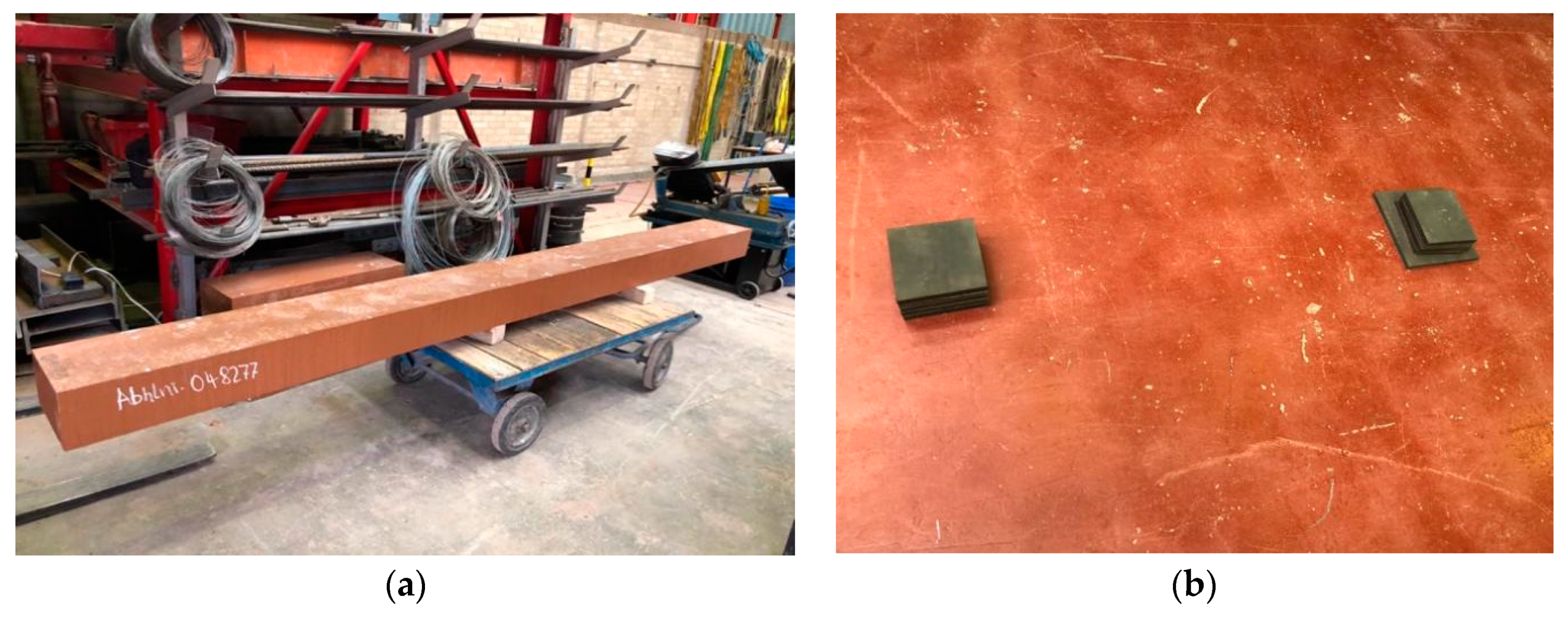
The two full-scale composite beam specimens have been prepared for load tests, as shown in Figure 2a. The dimension of each beam is 160 mm deep × 260 mm wide × 3300 mm long, kindly provided by an industry partner. The experimental investigations are conducted in accordance with EN 13230 (Test material, specifications, support conditions, loading procedures, and other requirements needed for bending tests on railway track concrete sleepers). Note that EN 13230 has some limitations in order to detect the failure mode of flexible composites. Especially, some experimental arrangements are adapted to examine the structural damage and the failure mode of the full-scale FFU composite beams [38,39,40,41]. In this study, modal tests have been conducted using an impact excitation technique in a free-support condition (or ‘free-free condition’). The damage and failure are observed using three-point bending tests following EN 13230, in order to investigate the damage and failure of the beams. The modal parameters of FFU composite beams under different conditions are then investigated.

2.2.1. Modal Testing

The dynamic modal parameters have been identified for both healthy and damaged conditions. It should be noted that bending tests are conducted to trigger different levels of damage. Firstly, both specimens are tested under healthy condition. This test requires laying two soft rubber cushions shown in Figure 2b. These very soft cushions have been placed underneath each sample, so that the free-free boundary conditions can be incited for the modal parameters of the sole specimens. This free-free condition is imperative if the dynamic parameters of an individual component are required in any like-for-like performance comparison.
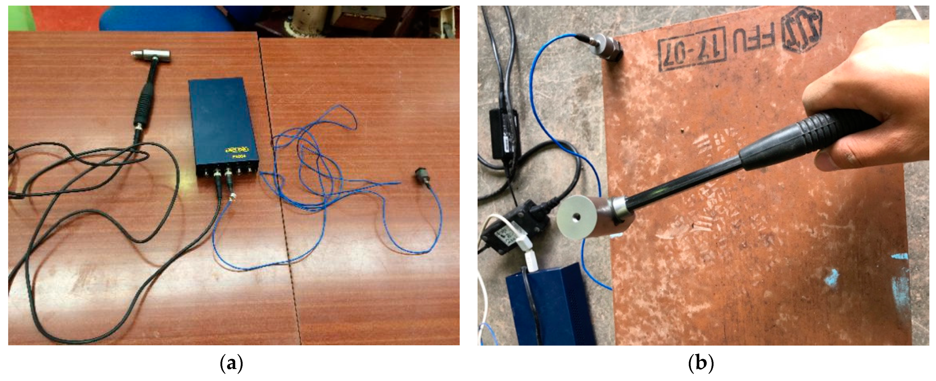
Secondly, the experimental modal analysis has been performed to identify dynamic parameters of the specimens under different severity states of damaged conditions. The equipment used for this test is a Prosig-P800 impact hammer as given in Figure 3a. The 34 uniform locations have been marked on the surface of each sample as the excitation locations of the impact hammer. The accelerometer is fixed at one corner to record the acceleration, as shown in Figure 3b. According to the EN 13230 criterion [41], the dynamic responses up to 2100 Hz are recorded. In addition, these attributes are clearly defined using a curve fitting method. Data modal analysis is a package that can create optimisation algorithms and provide relevant frequency-dependent shapes to explain the data sets. This data can be transformed into curve images; and mode shapes can be determined by the ‘animation drawing suite’.

2.2.2. Three-Point Bending Tests

According to EN 13230-2 [41], the standard requires positive and negative three-point bending tests for sleepers at the rail seat support. Only positive bending tests have been carried out due to the symmetrical shape of the samples. This means that the samples have the same positive and negative capacity. Also, the criterion requires articulated support and must be 100 mm wide, made of steel with Brinell: HBW > 240. A static load is applied at the mid-span to cause positive 3-point bending cracks and failure. Figure 4 shows the layout of the bending load process, also illustrates the excitation locations of the impact hammer, which have been strategically installed to perform two modal tests under different bending loads. Figure 5 demonstrates two pattern tests of the samples under different bending load conditions. The investigations are sufficiently performed in order to comply with BS EN 13230-1 standard [41].

2.3. Determination of Dynamic Elastic Modulus

Dynamic elastic properties of a material can thus be calculated if the mass, geometry, and mechanical resonant frequencies of the test sample can be measured. This means that the dynamic Young’s modulus can be identified utilizing the resonant frequency in either the bending or longitudinal mode of vibration, as given in Equation (1) [25,42], whilst the dynamic shear modulus, also known as modulus of rigidity, can be found by employing twisting resonant vibrations [23,43]. In this section, we only focus on the determination of dynamic elastic modulus in free-free boundary conditions (for future benchmarking purpose). This is because, based on the experimental results in the following part, it can be found that the first bending mode in a vertical plane obviously dominates the first resonant mode of vibration in free-free boundary conditions. By employing bending vibration modes, slender beams based on the Euler–Bernoulli theory of bending vibrations can be applicable to the test sample. The influences of rotational inertia and shear can be negligible generally. The equations derived on these assumptions are sufficient for relatively slender beams of lower modes. Nevertheless, this theory is likely to slightly overestimate the natural frequencies. According to Euler–Bernoulli’s basic equations of flexure, the dynamic elastic modulus in bending of a beam can be assessed under forced free or bending free vibrations. The dynamic elastic modulus in bending of a beam can be expressed as Equation (1):
( E d y ρ ) n = ( 2 π L F f , n ) 2 K n 4 β ,
where E d y is dynamic elastic modulus (Pa), n is mode number, L is free length (m), ρ is stabilized density (kg∙m−3), F f , n is frequency of nth mode (Hz), and K n is a coefficient related to the beam’s support condition and mode number (e.g., K 1 is equal to 4.73 for a free-free end condition and 1.785 for a fixed-free condition [44], as given in Table 2). Finally, β is the square value of gyration radius divided by free length as provided in Equation (2):
β = ( 1 L I A ) 2 = I L 2 A .
Herein, β denotes the square value of gyration radius divided by free length, L . I is the moment of inertia about the axis and A is the cross-section area. If no axis is specified, the centroidal axis is assumed.
It is important to note that Equation (1) is a conceptual equation of vibration, which ignores the influence of rotational deformation and shear load in a simulation. Nevertheless, for an application of using this equation, it could be dominated by L/h ratios (i.e., more than 58 in a fixed-free end condition or more than 20 in a free-free end condition) [45]. In this paper, the modeling of FFU composite beam does not take into account shear deformation and rotational bending effects (as defined by the Timoshenko theory), due to the ratio of L/h ≥ 20 (thin beam). Additionally, both previous equations are limited to isotropic materials. It is noted that the FFU composite beam model was considered as an isotropic material. In fact, this material would be considered to be anisotropic, but we measure its dynamic responses only in the vertical direction. Thus, the material can be considered conceptually to be isotropic. The following section presents the numerical investigations of a FFU composite beam modeling using the dynamic parameters obtained from the experiments in order to determine the dynamic elastic modulus of the beam.

2.4. A Finite-Element (FE) Model

A three-dimensional FFU composite beam model under free-free boundary conditions has been developed to study its dynamic response and compare with the experimental results. The Strand7 software [46] is used to model this 3D simulation, which employs 60 Euler–Bernoulli beam elements with 61 nodes, due to the model acting as a shallow beam. Figure 6 demonstrates the three-dimensional finite element model of a FFU composite beam. The modification for the geometric and material characteristics of these components has been based on the experimental data. The engineering properties are presented in Table 3 [47,48].

3. Results

3.1. Experimental Results

The results of the vibration tests for FFU composite beams under an ultimate load test and repeated load test for healthy and damaged conditions are presented in Table 4 and Table 5 and Figure 7 and Figure 8. The first five-mode shapes of vibration under ultimate and repeated load tests are shown in Table 4 and Table 5, respectively. For all beams, the first natural bending mode in a vertical plane obviously controlled the first resonant mode of vibration both under an ultimate load test and repeated load test. In addition, the lowest frequency corresponds to the natural bending mode, the second frequency to the lowest torsional mode, the third frequency to the second bending mode, the fourth frequency to the second torsional mode, and the fifth mode to the third bending mode. Clearly, the internal dynamic properties of FFU composite beams can be changed when damages occur.
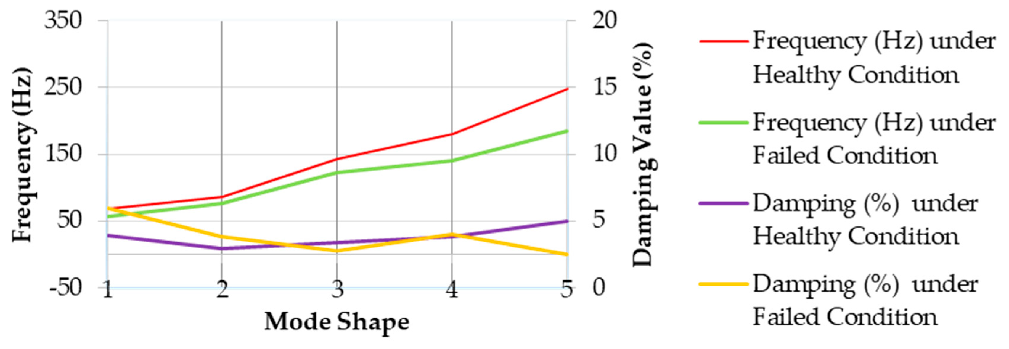
Table 4 exhibits the results of natural frequencies and damping values of the FFU composite beams under the ultimate load test. The differences between the natural frequencies of all mode shapes in healthy and failed conditions are 16.5%, 11.4%, 15.1%, 22.46%, and 25.27%, respectively. As shown in Figure 7, the frequencies of all five modes under failed conditions are lower than those under healthy conditions. For damping values, the value of the first mode damping values under failed conditions increased by 49%, compared with those under healthy conditions. There are several transverse damages on the beam surface for the first time under failure conditions, and there are cracks (30 mm in width). Nevertheless, the beam specimens remain the same and could completely recover without any load. After measurement and unloading, the residual bending deformation level of the material is only 2 mm.
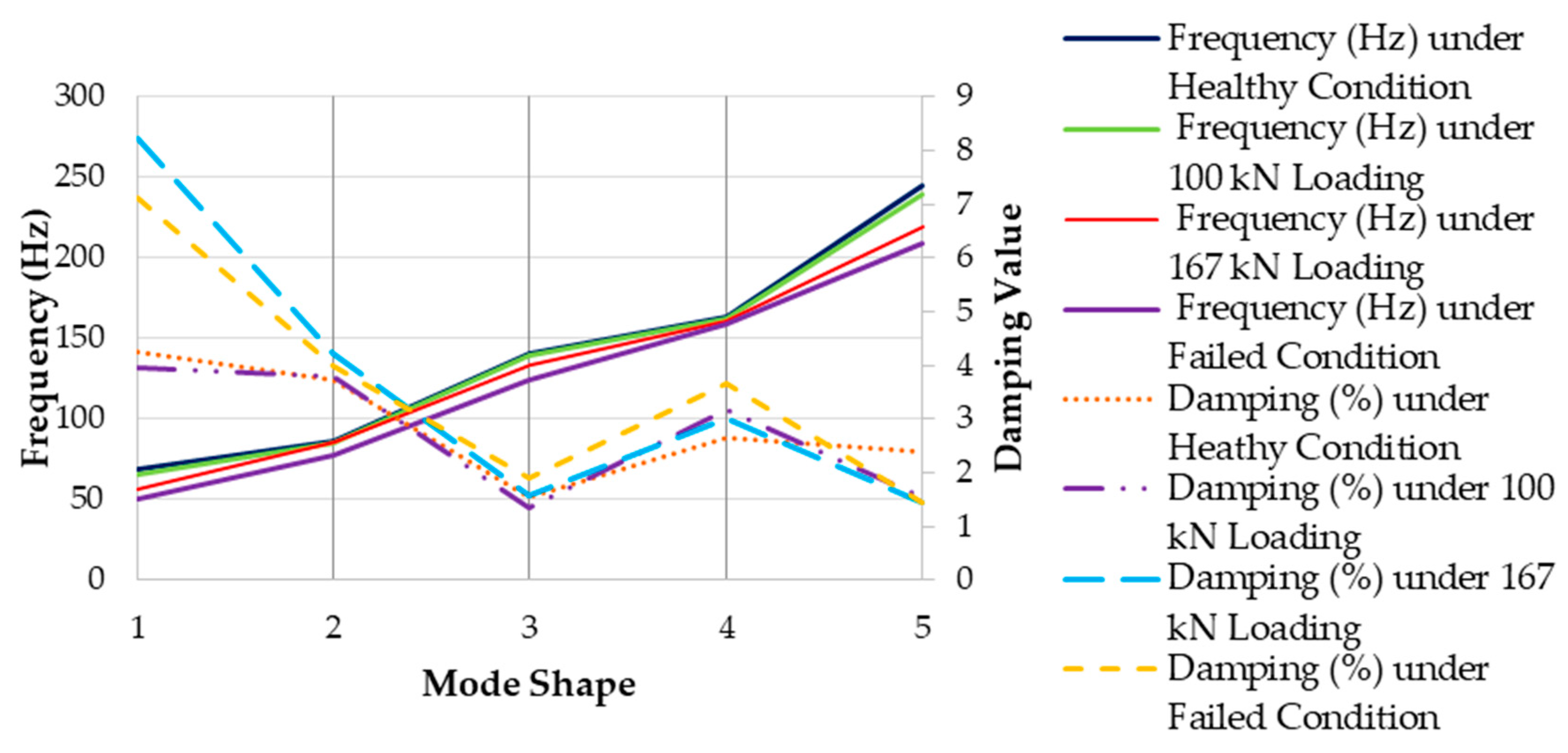
The dynamic behavior of the FFU composite beams under the repeated load test is demonstrated in Table 5 and Table 6 and Figure 8. In Table 5, it is clear that all modes have no obvious deviation before the load reached 100 kN. Beyond this load to the ultimate load, the frequencies of all five modes tend to reduce with percent variations of different mode shapes. The maximum difference of frequency is found in the first mode, approximately 27%, compared with the frequency under healthy conditions. Surprisingly, the frequencies of the fourth mode are unchanged under the different loading conditions. A comparison of natural frequencies and damping values between healthy and damaged conditions in all the five modes is presented in Table 6, which shows that there were maximum differences in natural frequencies and damping values between the healthy condition and the ultimate loading condition (170 kN). We note that the minimum difference in frequencies and damping values between the healthy condition and the damaged condition could be found under a load of 67 kN.
However, the different frequencies of the other modes reduce dramatically, as shown in Figure 8. In regards to damping values in Table 5, all the modes except the first and fifth mode are scant. Obviously, the difference of damping values between under 100 kN and 167 kN loading in the first mode is significantly high and increased two-fold from 3.94 to 8.24. In addition, the difference of damping values between healthy conditions and 67 kN loading in the fifth mode is considerable, which decreased by 36% from 2.39 to 1.53. It is clear that the dynamic modal parameters of FFU beams decrease when damages appear. These beams could reduce with the damage severity.

3.2. Numerical Results

Based on the frequencies experimentally obtained by the impact hammer excitation technique, dynamic Young’s modulus, E, can be computed using Equation (1). As shown in Table 7, the big difference of the Young’s modulus values is significant in the first bending mode and relatively small when compared with the Young’s modulus for FFU composite sleepers, E = 8.1 GPa, according to the reviews in [48,49].
In order to verify the model, the natural frequencies of a full-scale FFU beam in free-free conditions are calibrated against the existing experiments. The values of a dynamic elastic modulus in different bending modes obtained from Table 7 have been used in the finite element analysis. A comparison between numerical and experimental investigations for frequencies and mode shapes are given in Table 8, especially the experimental data based on the ultimate load test. The results are found to be in a very good agreement in all the first five modes. The maximum difference of frequencies between the numerical and experimental data is less than 4% in the second twisting mode, because of the effects of experimental disturbances in our laboratory. Additionally, there is a satisfied correlation between both results for the shifts in natural frequencies under free vibration. It is important to note that the numerical modal analysis of a FFU composite beam can only be achieved under free-free boundary conditions. This free-free boundary condition is commonly used for performance benchmarking of an individual component (i.e., like-for-like comparison), especially for railway sleepers and bearers, which are safety-critical components [50]. In the near future, the situ investigation into modal parameters of FFU composite beams can be further carried out in order to determine the effect of different boundary conditions (e.g., type of ballast aggregate, or resultant effects of particle size distribution, tamping) on vibration properties of the beams.

4. Conclusions

Dynamic modal parameters of FFU composites are extremely significant for the development of a realistic dynamic model of a railway track capable of predicting its dynamic responses for predictive and preventative maintenance to ensure railway safety. The results of the experimental and numerical modal analysis for Fiber-reinforced Foamed Urethane composite beams in free-free boundary conditions are indicated in this study. For the purpose of like-for-like performance benchmarking for a particular component, the free-free boundary condition is considered to be more suitable since the test results will not be affected by uncertainties stemmed from supports (e.g., dimension and particle size distribution of ballast, tamping technique, ballast geological properties). Full-scaled experiments have been performed to artificially create damage and failure in accordance with European standards. Dynamic parameter tests have been conducted by using an impact hammer excitation technique throughout the frequency range of interest: from 0 to 2100 Hz. According to experimental results, it provides the correlations between modal parameters and structural damage. Furthermore, the dynamic parameters obtained are later used to extract the dynamic elastic moduli. The results of frequency parameters under free-free conditions are in a very good agreement between experimental and numerical data with less than 4% discrepancy. Further research could be conducted to investigate the vibration characteristics of Fiber-reinforced Foamed Urethane composite beams in situ conditions in order to consider the influence of various ballast conditions on the natural frequencies, modal damping values, and vibration mode shapes of FFU composite beams under the in-situ boundary conditions. Some interesting novel findings from this research can be concluded as follows:
  • The first bending mode in a vertical plane obviously dominates the first resonant mode of vibration under a free-free condition;
  • The dynamic modal parameters of full-scale FFU composite beams reduce when damages occur. Thus, they decrease with damage severity;
  • The highest dynamic Young’s modulus of FFU composite beams is found in the resonant frequency of the first bending mode and also reduces when the second and third bending modes appear.

Author Contributions

Conceptualization, P.S. and S.K.; data curation, P.S. and A.L.O.d.M.; formal analysis, P.S., C.N., A.L.O.d.M., and S.K.; funding acquisition, S.K.; investigation, P.S., C.N., A.L.O.d.M., and S.K.; methodology, P.S., C.N., and S.K.; project administration, S.K.; resources, S.K.; software, S.K.; supervision, S.K.; validation, P.S., C.N., and A.L.O.d.M.; visualization, P.S., C.N., and A.L.O.d.M.; writing—original draft, P.S., C.N., and A.L.O.d.M.; writing—review & editing, S.K. All authors have read and agreed to the published version of the manuscript.

Funding

The authors wish to gratefully acknowledge the European Commission for the financial sponsorship of the H2020-MSCA-RISE Project No. 691135 “RISEN: Rail Infrastructure Systems Engineering Network,” which enables a global research network that tackles the grand challenge in railway infrastructure resilience and advanced sensing in extreme environments (www.risen2rail.eu). In addition, this project is partially supported by the European Commission’s Shift2Rail, H2020-S2R Project No. 730849 “S-Code: Switch and Crossing Optimal Design and Evaluation”. The APC is kindly sponsored by MDPI’s Invited Paper Program.

Conflicts of Interest

The authors declare no conflict of interest.

References

  1. Van Erp, G.; McKay, M. Recent Australian Developments in Fibre Composite Railway Sleepers. Electron. J. Struct. Eng. 2013, 13, 62–66. [Google Scholar]
  2. Manalo, A. Behaviour of Fibre Composite Sandwich Structures: A Case Study on Railway Sleeper Application. Ph.D. Thesis, Centre of Excellence in Engineered Fibre Composites Faculty of Engineering and Surveying University of Southern Queensland Toowoomba, Toowoomba, Australia, 2011. [Google Scholar]
  3. Ngamkhanong, C.; Kaewunruen, S.; Costa, B.J.A. State-of-the-Art Review of Railway Track Resilience Monitoring. Infrastructures 2018, 3, 3. [Google Scholar] [CrossRef] [Green Version]
  4. Gamage, E.K.; Kaewunruen, S.; Remennikov, A.M.; Ishida, T. Toughness of Railroad Concrete Crossties with Holes and Web Openings. Infrastructures 2017, 2, 3. [Google Scholar] [CrossRef] [Green Version]
  5. Kaewunruen, S. Monitoring in-service performance of fibre-reinforced foamed urethane material as timber-replacement sleepers/bearers in railway urban turnout systems. Struct. Monit. Maint. 2014, 1, 131–157. [Google Scholar]
  6. Kaewunruen, S. In situ performance of a complex urban turnout grillage system using fibre-reinforced foamed urethane (FFU) bearers. In Proceedings of the 10th World Congress on Rail Research, Sydney, Australia, 25–28 November 2013. [Google Scholar]
  7. Kaewunruen, S. Monitoring structural deterioration of railway turnout systems via dynamic wheel/rail interaction. Case Stud. Nondestr. Test. Eval. 2014, 1, 19–24. [Google Scholar] [CrossRef] [Green Version]
  8. Indraratna, B.; Salim, W.; Rujikiatkamjorn, C. Advanced Rail Geotechnology—Ballasted Track; CRC Press/Balkema: Leiden, The Netherlands, 2011. [Google Scholar]
  9. RailCorp. Timber Sleepers & Bearers; Engineering Specification SPC 231; RailCorp: Sydney, Australia, 2012.
  10. Kaewunruen, S.; Remennikov, A.M. Dynamic flexural influence on a railway concrete sleeper in track system due to a single wheel impact. Eng. Fail. Anal. 2009, 16, 705–712. [Google Scholar] [CrossRef]
  11. Remennikov, A.M.; Kaewunruen, S. A review of loading conditions for railway track structures due to train and track vertical interaction. Struct. Control. Health Monit. 2008, 15, 207–234. [Google Scholar] [CrossRef]
  12. Standards Australia. Australian Standards: AS3818.2 Timber; Standards Australia: Sydney, Australia, 2001. [Google Scholar]
  13. Dindar, S.; Kaewunruen, S.; An, M. Identification of Appropriate Risk Analysis Techniques for Railway Turnout Systems. J. Risk Res. 2016, 21, 974–995. [Google Scholar] [CrossRef]
  14. Pen, L.L. Track Behaviour: The Importance of the Sleeper to the Ballast Interface. Ph.D. Thesis, University of Southampton, Southampton, UK, 2008. [Google Scholar]
  15. Griffin, D.W.P.; Mirza, O.; Kwok, K.; Kaewunruen, S. Finite element modelling of modular precast composites for railway track support structure: A battle to save Sydney Harbour Bridge. Aust. J. Struct. Eng. 2015, 16, 150–168. [Google Scholar] [CrossRef]
  16. Kaewunruen, S.; Sengsri, P.; de Melo, A.L.O. Experimental and Numerical Investigations of Flexural Behaviour of Composite Bearers in Railway Switches and Crossings. In Sustainable Issues in Transportation Engineering; Mohammad, L., Abd El-Hakim, R., Eds.; Sustainable Civil Infrastructures; GeoMEast; Springer: Cham, Switzerland, 2019. [Google Scholar]
  17. Silva, E.A.; Pokropski, D.; You, R.; Kaewunruen, S. Comparison of structural design methods for railway composites and plastic sleepers and bearers. Aust. J. Struct. Eng. 2017, 18, 160–177. [Google Scholar] [CrossRef]
  18. Kaewunruen, S. Discussion of “Evaluation of an Innovative Composite Railway Sleeper for a Narrow-Gauge Track under Static Load” by Wahid Ferdous, Allan Manalo, Gerard Van Erp, Thiru Aravinthan, and Kazem Ghabraie. J. Compos. Constr. 2019, 23, 07018001. [Google Scholar] [CrossRef]
  19. Kaewunruen, S.; Remennikov, A.M.; Murray, M.H. Introducing a new limit states design concept to railway concrete sleepers: An Australian experience. Front. Mater. 2014, 1, 8. [Google Scholar] [CrossRef] [Green Version]
  20. Crystal Instruments. Basics of Structural Vibration Testing and Analysis. Available online: https://www.crystalinstruments.com/basics-of-modal-testing-and-analysis (accessed on 12 January 2020).
  21. Kaewunruen, S. Experimental and Numerical Studies for Evaluating Dynamic Behaviour of Prestressed Concrete Sleepers Subject to Severe Impact Loading. The University of Wollongong. Available online: http://ro.uow.edu.au/theses/277 (accessed on 8 January 2020).
  22. Remennikov, A.; Kaewunruen, S. Experimental Investigation on Dynamic Railway Sleeper/Ballast Interaction. Exp. Mech. 2006, 46, 57–66. [Google Scholar] [CrossRef]
  23. Pickett, G. Equations for computing elastic constants from flexural and torsional resonant frequencies of vibrating prisms and cylinders. ASTM Proc. 1945, 45, 846–865. [Google Scholar]
  24. Spinner, S.; Reichard, T.W.; Tefft, W.E. A Comparison of Experimental and Theoretical Relations Between Young’s Modulus and the Flexural and Longitudinal Resonance Frequencies of Uniform Bars. J. Res. Natl. Bur. Stand. Sect. A Phys. Chem. 1960, 64, 2–147. [Google Scholar] [CrossRef] [PubMed]
  25. Spinner, S.; Tefft, W.E. A Method for Determining Mechanical Resonance Frequencies and for Calculating Elastic Moduli from These Frequencies. ASTM Proc. 1961, 61, 1221–1238. [Google Scholar]
  26. ASTM Standard E 1876–07. Standard Test Method for Dynamic Young’s Modulus, Shear Modulus, and Poisson’s Ratio by Impulse Excitation of Vibration; ASTM International: West Conshohocken, PA, USA, 1876. [Google Scholar]
  27. Wesolowski, M.; Barkanov, E.; Rucevskis, S.; Chate, A.; La Delfa, G. Characterisation of elastic properties of laminated composites by non-destructive techniques. In Proceedings of the 17th International Conference on Composite Materials, Edinburgh, UK, 27–31 July 2009. [Google Scholar]
  28. Yu, L.; Wang, J.; Xia, D. Vibration Method for Elastic Modulus of Glued Laminated Beams. In Proceedings of the 3rd International Conference on Material, Mechanical and Manufacturing Engineering, IC3ME 2015, Guangzhou, China, 27–28 June 2015; Atlantis Press: Amsterdam, The Netherlands, 2015; pp. 1603–1606. [Google Scholar]
  29. Giaccu, G.F.; Meloni, D.; Valdès, M.; Fragiacomo, M. Dynamic determination of the modulus of elasticity of maritime pine cross-laminated panels using vibration methods. WIT Trans. Ecol. Environ. 2017, 226, 571–579. [Google Scholar]
  30. Ivanova, Y.; Partalin, T.; Georgiev, I. Characterisation of elastic properties of laminated composites by ultrasound and vibration. Sci. Proc. Sci. Tech. Union Mech. Eng. 2016, 1, 418–425. [Google Scholar]
  31. Gillich, G.R.; Samoilescu, G.; Berinde, F.; Chioncel, C.P. Experimental determination of the rubber dynamic rigidity and elasticity module by time-frequency measurements. Mater. Plast. 2007, 44, 18–21. [Google Scholar]
  32. Iancu, V.; Vasile, O.; Gillich, G.R. Modelling and Characterization of Hybrid Rubber-Based Earthquake Isolation Systems. Mater. Plast. 2012, 49, 237–241. [Google Scholar]
  33. Nedelcu, D.; Gillich, G.R.; Cziple, F.; Ciuca, I.; Padurean, I. Considerations about using polymers in adaptive guardrails construction. Mater. Plast. 2008, 45, 47–52. [Google Scholar]
  34. Roohnia, M. An Estimation of Dynamic Modulus of Elasticity in Cantilever Flexural Timber Beams. Drv. Ind. 2014, 65, 1–10. [Google Scholar] [CrossRef]
  35. Kubojima, Y.; Tonosaki, M.; Yoshihara, H. Young’s modulus obtained by flexural vibration test of a wooden beam with inhomogeneity of density. J. Wood Sci. 2006, 52, 20–24. [Google Scholar] [CrossRef]
  36. Lee, K.M.; Kim, D.S.; Kim, J.S. Determination of Dynamic Young’s Modulus of Concrete at Early Ages by Impact Resonance Test. KSCE J. Civ. Eng. 1997, 1, 11–18. [Google Scholar] [CrossRef]
  37. Kaewunruen, S.; Lewandrowski, T.; Chamniprasart, K. Dynamic responses of interspersed railway tracks to moving train loads. Int. J. Struct. Stab. Dyn. 2017, 18, 1850011. [Google Scholar] [CrossRef]
  38. Kaewunruen, S.; Ngamkhanong, C.; Papaelias, M.; Roberts, C. Wet/dry influence on behaviors of closed-cell polymeric cross-linked foams under static, dynamic and impact loads. Constr. Build. Mater. 2018, 187, 1092–1102. [Google Scholar] [CrossRef]
  39. Krezo, S.; Mirza, O.; Kaewunruen, S.; Sussman, J.M. Evaluation of CO2 emissions from railway resurfacing maintenance activities. Transp. Res. Part. D Transp. Environ. 2018, 65, 458–465. [Google Scholar] [CrossRef]
  40. Kaewunruen, S.; Lopes, L.M.C.; Papaelias, M.P. Georisks in railway systems under climate uncertainties by different types of sleeper/crosstie materials. Lowl. Technol. Int. 2018, 20, 77–86. [Google Scholar]
  41. BSI. BSI Standards Publication Railway Applications—Track—Concrete Sleepers and Bearers Part 2: Prestressed Monoblock Sleepers; BSI: London, UK, 2016. [Google Scholar]
  42. Kaewunruen, S. Systemic values of enhanced dynamic damping in concrete sleepers – Comments on the paper: Ahn S, Kwon S, Hwang Y-T, Koh H-I, Kim H-S, Park J. Complex structured polymer concrete sleeper for rolling noise reduction of high-speed train system. Comp, Struct. 2020, 234, 111711. [Google Scholar] [CrossRef]
  43. Resonance, S. Standard Test Method for Dynamic Young’s Modulus, Shear Modulus, and Poisson’s Ratio by Impulse Excitation of Vibration 1; ASTM International: West Conshohocken, PA, USA, 2005. [Google Scholar]
  44. Stokey, W.F. Chapter 7 Vibration of Systems Having Distributed Mass and Elasticity. In Shock and Vibration Handbook. 22 October 2001. Available online: https://www.globalspec.com/reference/64452/203279/chapter-7-vibration-of-systems-having-distributed-mass-and-elasticity (accessed on 1 February 2020).
  45. Kaewunruen, S.; Janeliukstis, R.; Ngamkhanong, C. Dynamic properties of fibre reinforced foamed urethane composites in wet and dry conditions. Mat. Today. Procs. 2020, 5, 690. [Google Scholar] [CrossRef]
  46. G+D Computing. Using Strand7 Introduction to the Strand7 Finite Element Analysis System; G+D Computing Pty Ltd.: Sydney, Australia, 2002. [Google Scholar]
  47. Kaewunruen, S.; Goto, K.; Xie, L. Failure modes of fibre reinforced foamed urethane composite beams: Full-scale experimental determination. Mat. Today. Procs. 2020, 5, 691. [Google Scholar] [CrossRef]
  48. Kaewunruen, S.; You, R.; Ishida, M. Composites for Timber-Replacement Bearers in Railway Switches and Crossings. Infrastructures 2017, 2, 13. [Google Scholar] [CrossRef] [Green Version]
  49. Sengsri, P.; Ngamkhanong, C.; Melo, A.L.O.; Papaelias, M.; Kaewunruen, S. Damage Detection in Fiber-Reinforced Foamed Urethane Composite Railway Bearers Using Acoustic Emissions. Infrastructures 2020, 5, 50. [Google Scholar] [CrossRef]
  50. Kaewunruen, S.; Sussman, J.M.; Matsumoto, A. Grand Challenges in Transportation and Transit Systems. Front. Built Environ. 2016, 2, 4. [Google Scholar] [CrossRef] [Green Version]
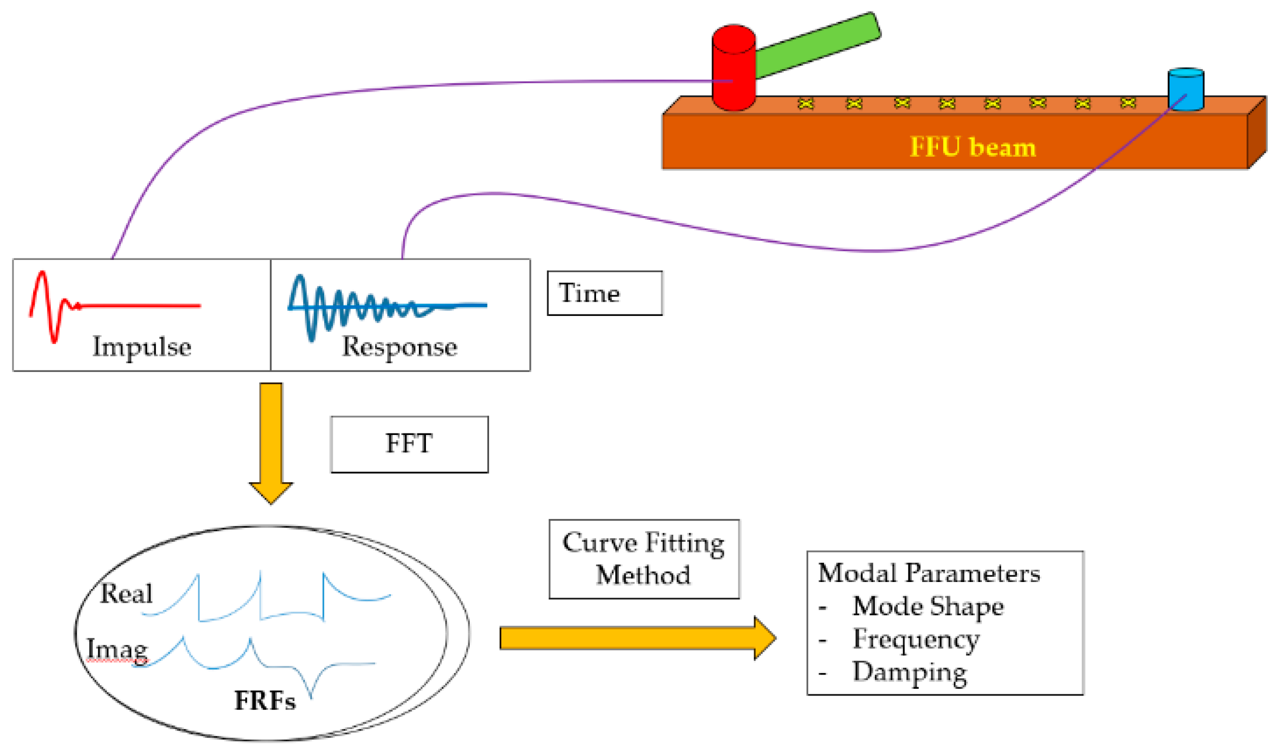
Figure 1. Modal testing and analysis.
Vibration 03 00014 g001
Figure 2. (a) FFU 17-06 specimens and (b) rubber cushions.
Vibration 03 00014 g002
Figure 3. (a) PROSIG-P800 impact hammer and (b) excitation locations and an accelerometer position.
Vibration 03 00014 g003
Figure 4. Testing arrangement of a full-scale FFU composite beam under bending loads.
Vibration 03 00014 g004aVibration 03 00014 g004b
Figure 5. Testing procedure of ultimate load test and repeated load test.
Vibration 03 00014 g005
Figure 6. Finite element modeling of a FFU composite beam in free-free conditions.
Vibration 03 00014 g006
Figure 7. Frequencies against damping values over mode shapes under ultimate load test for healthy and failed conditions.
Vibration 03 00014 g007
Figure 8. Frequencies against damping values over mode shapes under repeated load test for healthy and damaged conditions.
Vibration 03 00014 g008
Table 1. Static properties of Fiber-reinforced Foamed Urethane (FFU) material.
Properties [37]UnitsFFU Sleepers and Bearers [6]
NewAfter 10 Years UsedAfter 15 Years UsedAfter 30 Years Used
Elastic ModulusGPa8.108.048.798.41
Bending StrengthGPa0.1420.1250.1310.116
Shear StrengthMPa109.59.67
Vertical Compressive StrengthMPa58666355
Densitykg/m3740740740740
Service LifeYears50403520
HardnessMPa282517-
Table 2. Dimensionless coefficients for computing the frequencies of a FFU composite beam in free-free conditions.
Mode No.123456
K n 0 (Translation)4.7307.85310.99614.137 ( 2 n 1 ) π 2
Table 3. Geometric parameters employed in the dynamic simulation.
Parameter lists ValuesUnits
Density740kg/m3
Length3.3m
Cross-section area0.16 × 0.26 = 0.042m2
Table 4. Frequencies, damping values, and mode shapes under ultimate load test for healthy and failed conditions.
Healthy ConditionFailed ConditionDifference
Frequency (Hz)Damping (%)Frequency (Hz)Damping (%)Frequency (Hz)Damping (%)
Mode 1
(1st bending)
Vibration 03 00014 i001
68.23
3.96 Vibration 03 00014 i002
56.92
5.911.311.94
Mode 2
(1st twisting)
Vibration 03 00014 i003
85.78
2.98 Vibration 03 00014 i004
75.94
3.839.840.85
Mode 3
(2nd bending)
Vibration 03 00014 i005
143.61
3.37 Vibration 03 00014 i006
121.87
2.821.740.57
Mode 4
(2nd twisting)
Vibration 03 00014 i007
180.14
3.85 Vibration 03 00014 i008
139.68
3.9940.460.14
Mode 5
(3rd bending)
Vibration 03 00014 i009
247.96
4.96 Vibration 03 00014 i010
185.28
2.5362.682.43
Table 5. Frequencies, damping values, and mode shapes under repeated load test for healthy and damaged conditions.
Healthy67 kN100 kN167 kN170 kN (Failed)
Frequency (Hz)/Damping (%)
Mode 1 (1st bending)
Vibration 03 00014 i011 Vibration 03 00014 i012 Vibration 03 00014 i013 Vibration 03 00014 i014 Vibration 03 00014 i015
69.2/4.2368.03/5.04 65.84/3.9455.99/8.2450.44/7.12
Mode 2 (1st twisting)
Vibration 03 00014 i016 Vibration 03 00014 i017 Vibration 03 00014 i018 Vibration 03 00014 i019 Vibration 03 00014 i020
85.63/1.5584.8/3.8485.24/3.7885.54/4.2277.31/3.97
Mode 3 (2nd bending)
Vibration 03 00014 i021 Vibration 03 00014 i022 Vibration 03 00014 i023 Vibration 03 00014 i024 Vibration 03 00014 i025
140.09/1.55139.88/1.6139.04/1.35132.98/1.58124.08/1.9
Mode 4 (2nd twisting)
Vibration 03 00014 i026 Vibration 03 00014 i027 Vibration 03 00014 i028 Vibration 03 00014 i029 Vibration 03 00014 i030
163.3/2.66162.43/3.16162.13/3.16160.82/3.00159.07/3.66
Mode 5 (3rd bending)
Vibration 03 00014 i031 Vibration 03 00014 i032 Vibration 03 00014 i033 Vibration 03 00014 i034 Vibration 03 00014 i035
244.77/2.39241.69/1.53239.30/1.54219.40/1.44209.17/1.44
Table 6. Relative values of frequencies and damping to healthy condition.
Difference in Frequencies (Hz)/Damping (%)
No. Mode67 kN100 kN167 kN170 kN (Failed)
11.17/0.813.36/0.2913.21/4.0118.76/2.89
20.83/2.290.39/2.230.09/2.678.32/2.42
30.21/0.051.05/0.207.11/0.0316.01/0.35
40.87/0.501.17/0.502.48/0.344.23/1.00
53.08/0.865.47/0.8525.37/0.9535.60/0.95
Table 7. Determination of dynamic Young’s modulus from dynamic measurements in free-free end conditions.
Mode No.Experimental Frequency (Hz)Dynamic Young’s Modulus, E (GPa)
1 (bending)68.2315.34
2 (twisting)85.78-
3 (bending)143.618.81
4 (twisting)180.14-
5 (bending)247.966.83
Table 8. Natural frequencies of a conceptual FFU composite beam (Hz) in the free-free conditions.
Mode No.Mode ShapeNumerical (Hz)Experimental (Hz)Difference (%)
1
(First Bending)
Vibration 03 00014 i03668.7068.230.69
2
(First Twisting)
Vibration 03 00014 i03786.8285.781.21
3
(Second Bending)
Vibration 03 00014 i038143.44143.610.12
4
(Second Twisting)
Vibration 03 00014 i039173.58180.143.64
5
(Third Bending)
Vibration 03 00014 i040247.44247.960.21